

Revision F, 12/10/2004
1800 Overhead Projector
Illustrated Parts Breakdown
3M Visual Systems Department OHP Service Documentation Resource
6801 River Place Boulevard Copyright © 3M 2004. All Rights Reserved
Austin, Texas 78726-9000 78-6970-7536-0

Revision History
Original Issue date: 10/2001
The release date, revision level, pages changed and a description of the modifications are listed below.
Revision Date Page(s) Changed Description
Rev A 10/2001 All pages First edition released
Rev B 1/2002 Figure 1 Added Light Shield Kit
Individual parts
Rev C 6/2002 All pages
Rev D 8/2002 Figures 5, 8-14
Rev E 6/2003 All pages
All pages
Section 4,
Page 9
Section 5,
Pages 10 and 11
Section 7,
Page 14
Rev F 10/2004
Pages 16 and 17
Section 8,
Section 18,
Page 29
Section 19,
Page 31
Appendix A
All rights reserved. No part of this book covered by the copyrights hereon may be reproduced or copied
in any form or by any means-graphic, electronic, or mechanical, including photocopying, taping or
information storage and retrieval systems-without written permission of 3M Visual Systems Division.
combined into
modules and kits
Added Post Handle,
Lamp Module kit
content, OUS motor,
and U.S. Roll Film Kit.
New art and parts
listings for kits,
modules, and
individual parts.
Figure numbers and
most tables have new
layout.
New Arm Kit names
and part numbers.
New Arm section
added for S/Ns above
18040828.
Added On/Off Button
Kit to Top Cover art.
New Top Cover
section added for
clipped-in glass.
New 120V Fan Motor
name and part
number.
New 120V and 230V
Fan Motor names and
part numbers.
New information
added.
i

3M™ Overhead Projector 1800 Illustrated Parts Breakdown
Table of Contents
TABLE OF CONTENTS .............................................................................................................................................................0
LLUSTRATED PARTS BREAKDOWN (IPB) ..............................................................................................................................1
I
UICK REFERENCE PARTS INDEX...........................................................................................................................................2
Q
ECTION 0. MACHINE OVERVIEW ........................................................................................................................................3
S
ECTION 1. INVERTED HEAD ASSEMBLY..............................................................................................................................4
S
ECTION 2. OPEN HEAD ASSEMBLY.....................................................................................................................................5
S
ECTION 3. CLOSED HEAD ASSEMBLY.................................................................................................................................6
S
ECTION 4. ARM ASSEMBLY (SERIAL NUMBER 18040827 AND BELOW)..............................................................................8
S
ECTION 5. ARM ASSEMBLY (SERIAL NUMBER 18040828 AND ABOVE) ............................................................................10
S
ECTION 6. POST MOUNTING HARDWARE..........................................................................................................................12
S
ECTION 7. TOP COVER ASSEMBLY (WITH TAPED-IN STAGE GLASS) ..................................................................................14
S
ECTION 8. TOP COVER ASSEMBLY (WITH CLIPPED-IN STAGE GLASS)................................................................................16
S
ECTION 9. BASE ASSEMBLY .............................................................................................................................................18
S
ECTION 10. LAMP HOUSING (SINGLE ENX/FXL).............................................................................................................20
S
ECTION 11. LAMP HOUSING (DUAL ENX/FXL)...............................................................................................................21
S
ECTION 12. LAMP HOUSING (SINGLE FNT)......................................................................................................................22
S
ECTION 13. LAMP HOUSING (DUAL FNT)........................................................................................................................23
S
ECTION 14. LAMP HOUSING (DUAL EVD) .......................................................................................................................24
S
ECTION 15. LAMP ASSEMBLY...........................................................................................................................................25
S
ECTION 16. COOLING FAN ASSEMBLY..............................................................................................................................26
S
ECTION 17. ROLL FILM KIT..............................................................................................................................................27
S
ECTION 18. WIRE JUMPERS (ENX AND FXL) ..................................................................................................................28
S
ECTION 19. WIRE JUMPERS (EVD AND FNT) ..................................................................................................................30
S
ECTION 20. PLASTIC PARTS KIT .......................................................................................................................................32
S
ECTION 21. SMALL ELECTRICAL PARTS KIT.....................................................................................................................32
S
ECTION 22. HARDWARE KIT.............................................................................................................................................33
S
APPENDIX A – 1800 (U.S.) SPECIFICATIONS..............................................................................................................34
APPENDIX A – 1800 (O.U.S.) SPECIFICATIONS..........................................................................................................36
IMPORTANT NOTICE
3M reserves the right to sell or furnish NEW OR RECONDITIONED PARTS.
New and reconditioned parts are covered by the same 3M new parts limited warranty.
© 3M 2004 0
3M™ Overhead Projector 1800 Illustrated Parts Breakdown
Illustrated Parts Breakdown (IPB)
This Illustrated Parts Breakdown (IPB) Manual contains the information necessary to locate and identify
assemblies, sub-assemblies, and specific parts of the 1800 Overhead Projector.
Part Numbers
All components available on a replacement basis are listed with their 3M identification number. The
parts identification list opposite each illustration provides the description adequate to identify
components. If the component is available only as part of the next higher assembly, the description
column provides the next higher assembly description or identification number.
Locating and Identifying a Part
If physical appearance and general location of an item are known:
1. Use the IPB Section Titles to help determine which assembly or sub-assembly includes the item.
2. Refer to the view for the assembly or sub-assembly and locate the item on the exploded view. Match the part
callout number to the corresponding number in the parts list.
3. Parts shown inside a dashed box can only be ordered as an assembly. Any part or mounting hardware shown
outside the box is not included with the assembly.
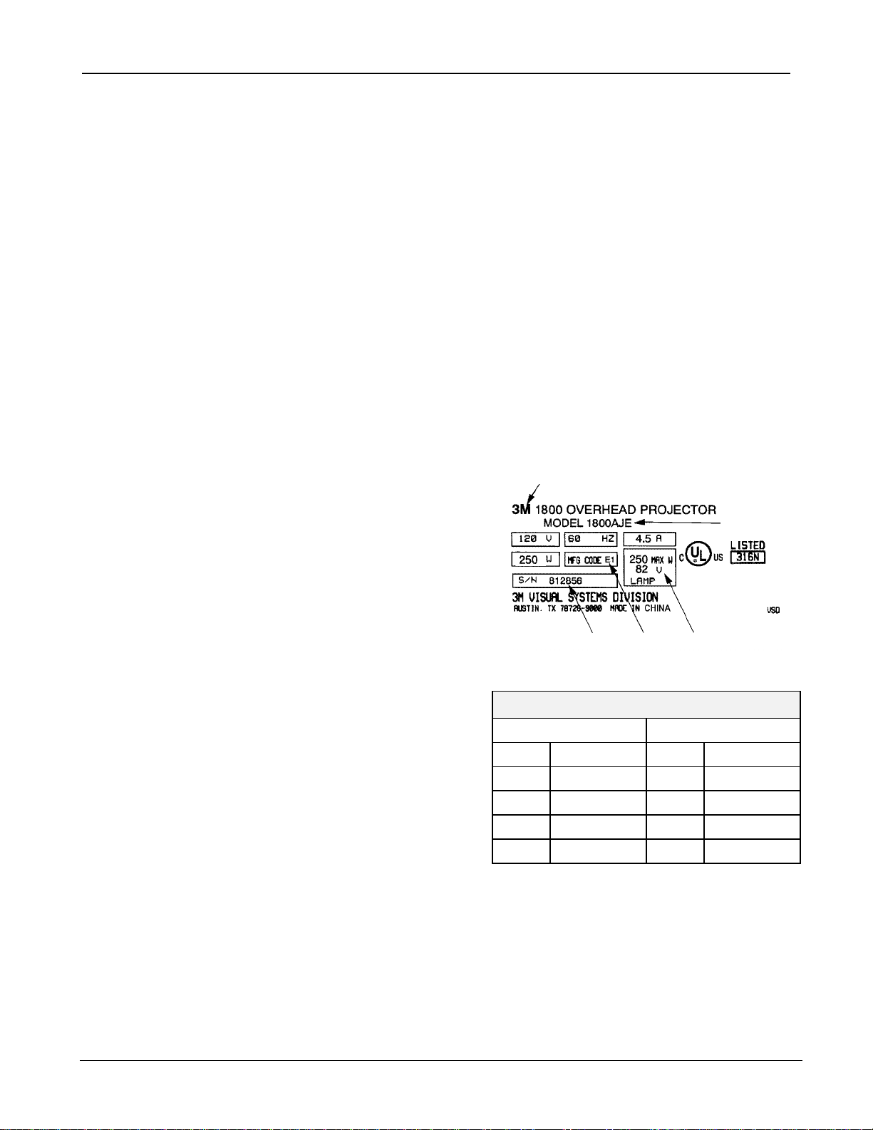
Machine Identification Plate
The serial number plate for the 1800 is located on the
bottom panel of the projector. The Machine Identification
Plate is divided into the following components:
1
2
1. Product Name: The specific version number of the
projector.
2. Model Number/Alpha Code: The series number of the
projector followed by a three or four character alpha code
identifier. The Alpha Code indicates the design level,
specific product characteristics, power cord or
distribution specific to a country.
3. Lamp: The electrical rating of the lamp.
4. MFG Code: The MFG Code indicates the year and
quarter the projector was built.
5. S/N: The serial number assigned to this projector.
K 2001 1 Jan-Mar
5 4 3
MFG Code
Letter Digit
Ordering Parts
When ordering parts, include the following information:
1. Machine model number and serial number.
2. Parts identification number.
3. Part description.
4. Quantity required.
L 2002 2 Apr-Jun
M 2003 3 Jul-Sep
A 2004 4 Oct-Dec
C 2005 1 Jan-Mar
For U.S. retail customers: Call 1-800-650-8429, or fax 1-800-650-9268. Dealers: Refer to Dealers
Guide. 3M Subsidiaries: Contact Export Operations.
© 3M 2004 1

3M™ Overhead Projector 1800 Illustrated Parts Breakdown
Quick Reference Parts Index
Description (By machine location) Part Number Section No. Item No.
Inverted Singlet Head Module 78-8120-8508-8 1 1
Inverted Triplet Head Module 78-8120-8509-6 1 2
Inverted Mirror Module 78-8120-8498-2 1 3
Light Shield Kit 78-8120-4070-3 1 9
Open Singlet Head Module 78-8120-8507-0 2 1
Open Mirror Module 78-8120-8499-0 2 2
Closed Head Module, Singlet 78-8120-8506-2 3 1
Closed Head Module, Doublet 78-8120-8505-4 3 2
Arm Kit (Includes basic post) 78-8120-8575-7 4 & 5 1A
Arm/Offset Post Kit 78-8120-8576-5 4 & 5 1B
Post Pivot Kit 78-8120-8516-1 6 1
Post, Basic Arm 78-8120-8514-6 6 2
Offset Post Pivot Kit 78-8120-8515-3 6 3
Post, Inverted Arm 78-8120-8513-8 6 4
Top Cover Modules (U.S. and A4) See Sections 7 & 8 7 & 8 1A – 1D
Fresnel Lens, Dual Element – 182.5 mm 78-8120-8504-7 7 & 8 6
Fresnel Lens, Dual Element (Inverted Singlet) – 175.3mm 78-8120-8502-1 7 6
On/Off Button Kit, Red 78-8120-8563-3 7 & 8 8A
On/Off Button Kit, Blue 78-8120-8564-1 7 & 8 8B
Base Mirror Module (EVD/FNT) 78-8120-8511-2 9 1
Base Mirror Module (ENX/FXL) 78-8120-8512-0 9 2
Base Module 78-8120-8517-9 9 8
Lamp Housing Kit 78-8120-8520-3 9 9
Transformers See Section 9 9 4A – 4D
Power Cord, 120V (U.S. only) 78-8120-3184-3 9 11
ENX/FXL Single Lamp Socket 78-8120-3197-5 10 1
ENX/FXL Dual Lamp Socket 78-8120-3196-7 11 1
FNT Single Lamp Socket 78-8120-4003-4 12 8
FNT Dual Lamp Socket 78-8120-3193-4 13 4
EVD Dual Lamp Socket 78-8120-3193-4 14 4
Lamp, ENX 78-8011-1186-1 10 & 11 4A, 5A
Lamp, FXL 78-8073-7100-6 10 & 11 4B, 5B
Lamp, FNT 78-8054-1175-4 12 & 13 3, 5
Lamp, EVD 78-8079-8791-8 14 5
120V Fan Motor Assembly XO-0038-1567-7 16 5
230V Fan Motor Assembly XO-0038-1568-5 16 4
Roller Kit See Section 17 17 1 – 4
© 3M 2004 2
3M™ Overhead Projector 1800 Illustrated Parts Breakdown
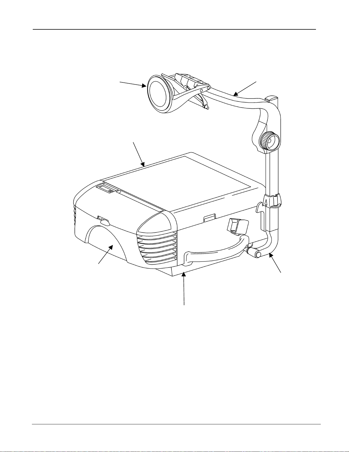
Section 0. Machine Overview
Head Assembly
(See Sections 1, 2, and 3)
Top Cover Assembly
(See Sections 7 and 8)
Arm Assembly
(See Sections 4 and 5)
ENX/FXL Lamp Housing
(Single and Dual)
(See Sections 10 and 11)
FNT Lamp Housing
(Single and Dual)
(See Sections 12 and 13)
EVD Lamp Housing
(Dual)
(See Section 14)
Lamp Assembly
(See Section 15)
Cooling Fan Assembly
(See Section 16)
© 3M 2004 3
Base Assembly
(See Section 9)
Post Mounting Hardware
(See Section 6)
(See Section 17)
Wire Jumpers
(See Sections 18 and 19)
Plastic Parts Kit
(See Section 20)
Electrical Parts Kit
(See Section 21)
Hardware Kit
(See Section 22)
Roller Kit
3M™ Overhead Projector 1800 Illustrated Parts Breakdown
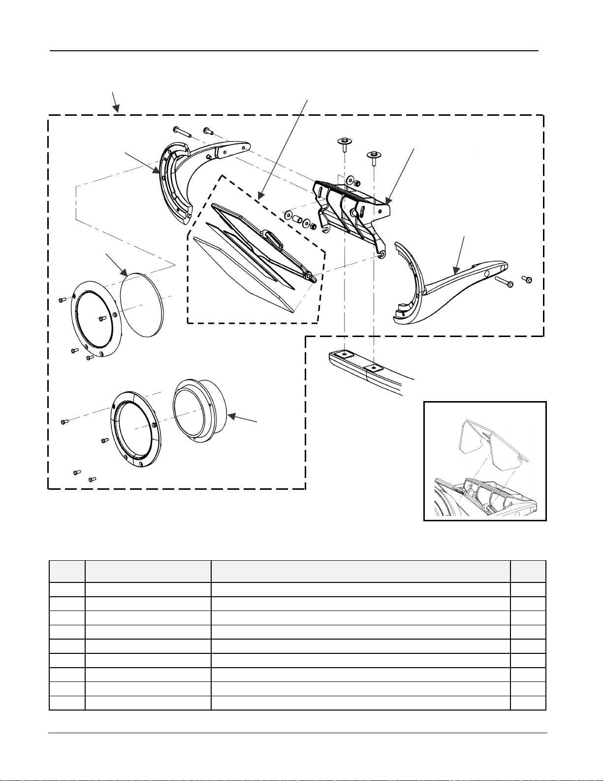
1,2
Section 1. Inverted Head Assembly
3
6
4
7
5
Inverted Singlet Head only
8
Light Shield Kit
Inverted Triplet Head only
Note: Screws, nuts, bolts, clips, and other small hardware
are also contained in the Hardware Kit: P/N 78-8120-8523-7
(Refer to Section 22).
Inverted Head Assembly Parts List
Item 3M Part Number Description Qty.
1 78-8120-8508-8 Inverted Singlet Head Module 1
2 78-8120-8509-6 Inverted Triplet Head Module 1
3 78-8120-8498-2 Inverted Mirror Module (Includes Mirror, Tape, and Holder) 1
4 78-8120-3158-7 Mount, Inverted Head 1
5 78-8120-3154-6 Yoke, Triplet, Left 1
6 78-8120-3155-3 Yoke, Triplet, Right 1
7 78-8096-5792-3 Lens, Wide Angle (254.78mm) 1
8 78-8097-3693-3 Lens, Triplet (345mm) 1
9 78-8120-4070-3 Light Shield Kit (Optional) 1
© 3M 2004 4
3M™ Overhead Projector 1800 Illustrated Parts Breakdown
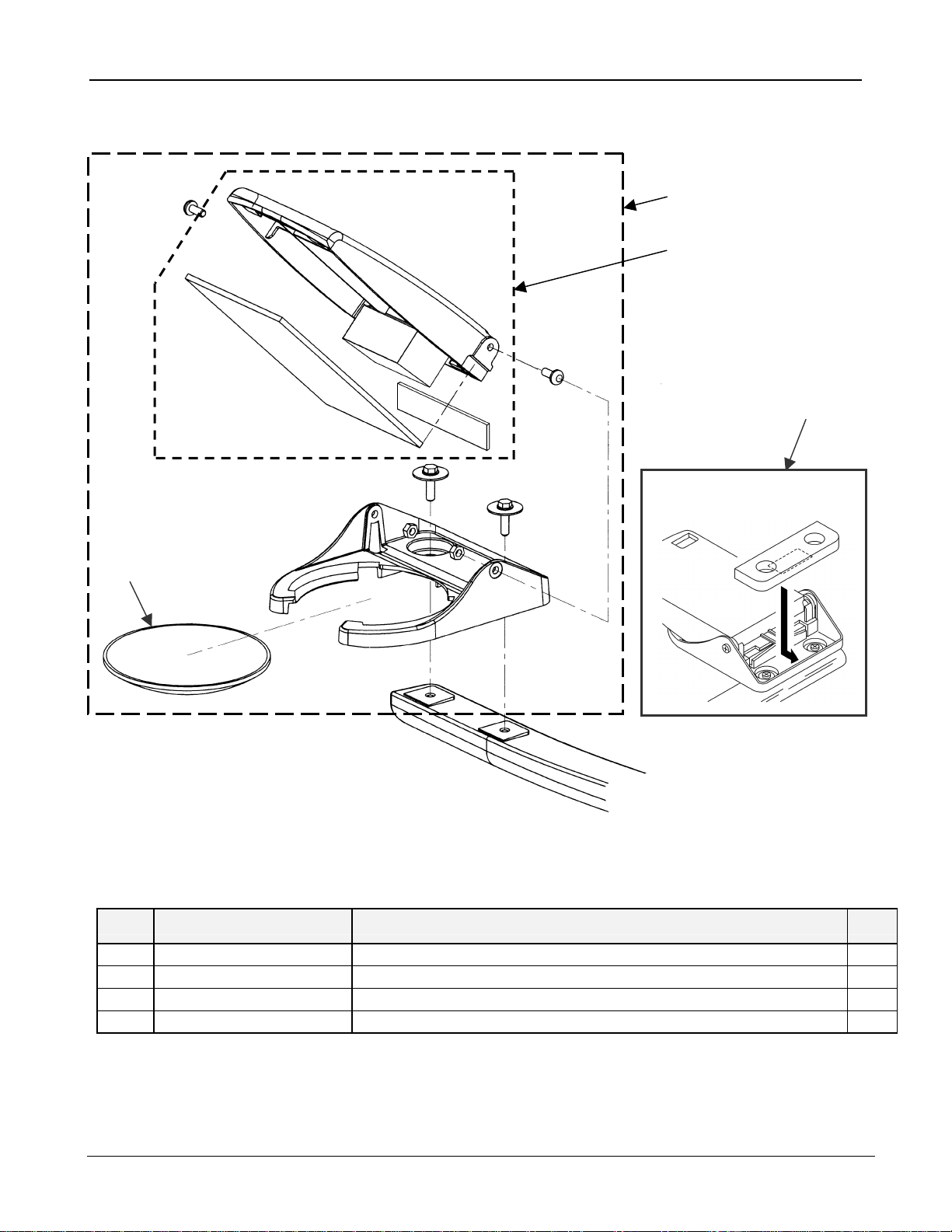
Section 2. Open Head Assembly
3
Note: Screws, nuts, bolts, clips, and other small
hardware are also contained in the Hardware Kit:
P/N 78-8120-8523-7 (Refer to Section 22).
Open Head Assembly Parts List
1
2
4
Head Stabilizer Kit
Item 3M Part Number Description Qty.
1 78-8120-8507-0 Open Singlet Head Module 1
2 78-8120-8499-0 Open Mirror Module 1
3 78-8014-8951-5 Lens, Wide Angle, Singlet (293mm) 1
4 78-8120-8565-8 Head Stabilizer Kit 1
© 3M 2004 5
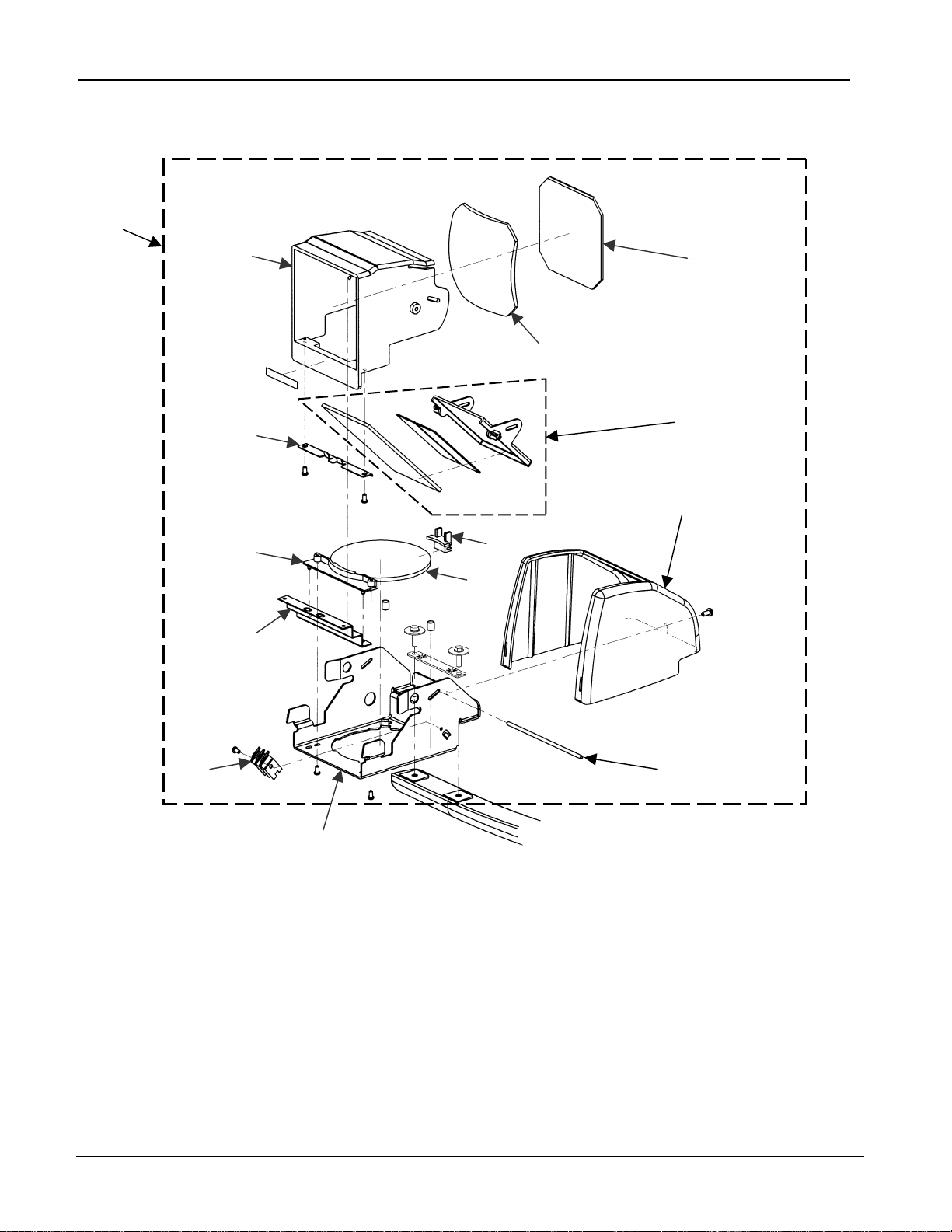
3M™ Overhead Projector 1800 Illustrated Parts Breakdown
Section 3. Closed Head Assembly
1, 2
3
6
15
14
4
(Singlet Head only)
5
9
10
7
8
13
12
Note: Screws, nuts, bolts, clips, and other small hardware
are also contained in the Hardware Kit: P/N 78-8120-8523-7
(Refer to Section 22).
© 3M 2004 6
11

3M™ Overhead Projector 1800 Illustrated Parts Breakdown
Closed Head Assembly Parts List
Item 3M Part Number Description Qty.
1 78-8120-8506-2 Closed Head Module, Singlet (Includes Mirror Housing Assy.) 1
2 78-8120-8505-4 Closed Head Module, Doublet (Includes Mirror Housing Assy.) 1
3 78-8064-1562-2 Housing, Exit Lens 1
4 78-8073-2982-2 Glass, Articulate Head, Coated (Singlet only) 1
5 78-8014-8812-9 Lens, Articulate 1
6 78-8064-1602-6 Clamp, Dust Shield 1
7 78-8064-1643-0 Mount, Lens, Singlet 1
8A 78-8073-2980-6 Lens, Wide Angle (Singlet only) 1
8B 78-8011-1440-2 Lens, Meniscus (Doublet only) 1
9 78-8064-1457-5 Mirror Housing Assembly 1
10 78-8120-3122-3 Cover, Doublet, Articulate 1
11 78-8011-1445-1 Pivot, Rod 1
12 78-8120-3121-5 Bracket, Lens 1
13 78-8014-8817-8 Spring, Tension 1
14 78-8064-1797-4 Shield, Dust 1
15A 78-8064-1596-0 Clamp, Lens, Singlet (Singlet only) 1
15B 78-8064-1595-2 Clamp, Lens (Doublet only) 1
16 78-8054-1791-8 Clamp, Lens Dust Shield, Singlet (Not shown) 1
17 78-8064-1646-3 Tubing, Lens (Not shown) 1
© 3M 2004 7

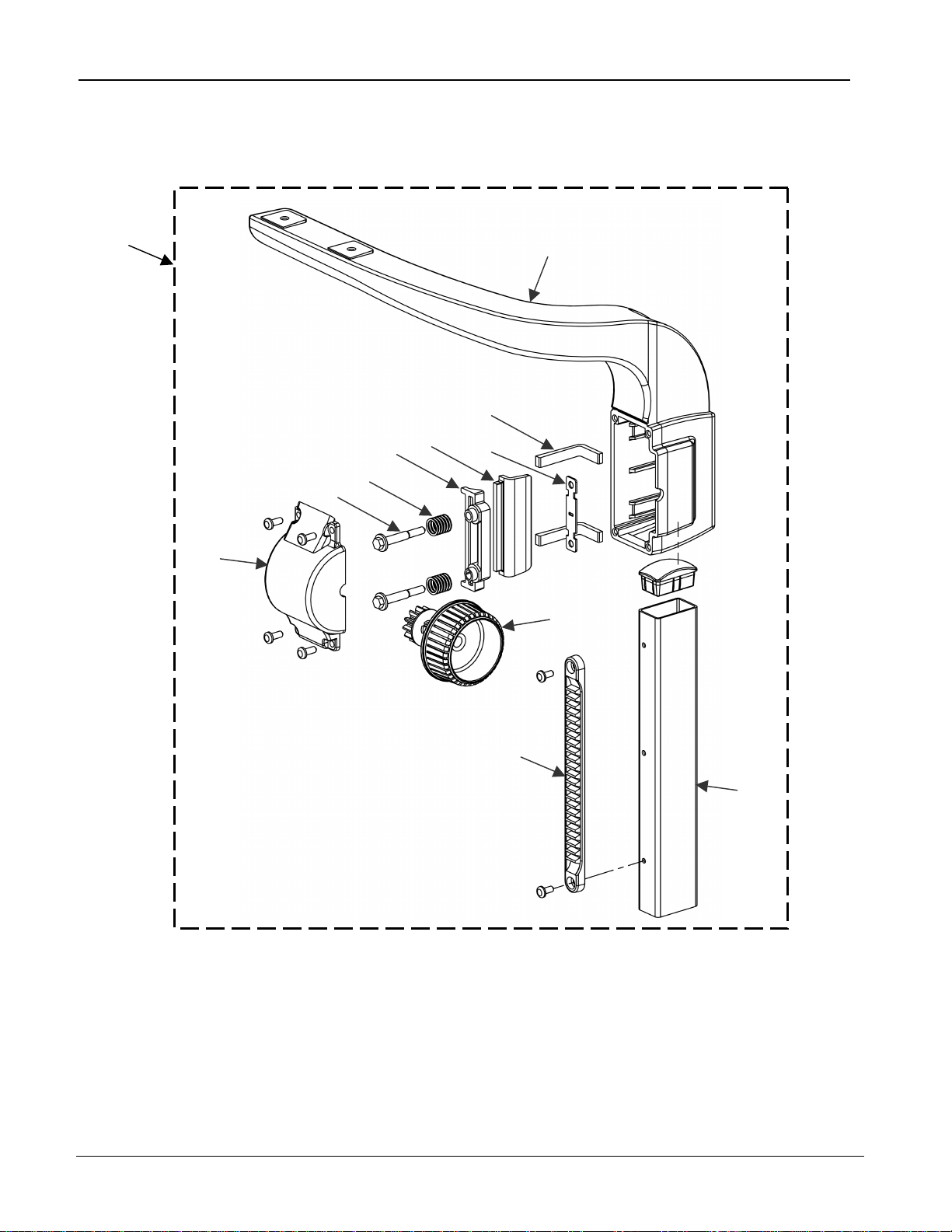
3M™ Overhead Projector 1800 Illustrated Parts Breakdown
Section 4. Arm Assembly
(Serial number 18040827 and below)
3
4
1
5
2
6
8
7
Note: Screws, nuts, bolts, clips, and other small hardware
are also contained in the Hardware Kit: P/N 78-8120-8523-7
(Refer to Section 22).
© 3M 2004 8

3M™ Overhead Projector 1800 Illustrated Parts Breakdown
Arm Assembly Parts List
(Serial number 18040827 and below)
Item 3M Part Number Description Qty.
1A 78-8120-8575-7 Arm Kit (includes basic post) 1
1B 78-8120-8576-5 Arm / Offset Post Kit 1
2 - - - Arm, Focus (must order 78-8120-8575-7) 2
3 78-8120-4017-4 Pad, Tension 1
4 78-8120-3069-6 Pad 1
5 78-8120-3142-1 Cap, Focus 1
6 78-8120-3153-8 Knob, Focus Gear, Blue 1
7 78-8079-8744-7 Rack, Focus 1
8A 78-8120-8513-8 Post, Inverted Arm 1
8B 78-8120-8514-6 Post, Basic Arm 1
9 78-8120-8537-7 Arm / Post / with Inverted Singlet Head Assembly (Not shown) 1
10 78-8120-8539-3 Arm / Post With Inverted Triplet Head Assembly (Not shown) 1
© 3M 2004 9
3M™ Overhead Projector 1800 Illustrated Parts Breakdown
Section 5. Arm Assembly
(Serial number 18040828 and above)
1
3
5
6
7
8
4
2
9
10
11
12
© 3M 2004 10

3M™ Overhead Projector 1800 Illustrated Parts Breakdown
Arm Assembly Parts List
(Serial number 18040828 and above)
Item 3M Part Number Description Qty.
1A 78-8120-8575-7 Arm Kit (includes basic post) 1
1B 78-8120-8576-5 Arm / Offset Post Assembly Kit 1
2 - - - Arm, Focus (must order 78-8120-8575-7) 2
3 See note Pad, Insert 2
4 See note Plate, Standoff 1
5 See note Clamp, friction 1
6 See note Pressure Bar 1
7 See note Spring, Compression 2
8 See note Screws, Shoulder 2
9 See note Cap, Focus 1
10 RO-0038-1149-2 Knob, Focus Gear, Blue 1
11 78-8079-8744-7 Rack, Focus 1
12A 78-8120-8513-8 Post, Inverted Arm 1
12B 78-8120-8514-6 Post, Basic Arm 1
13 78-8120-8537-7 Arm / Post / Inverted Singlet Head Assembly (Not shown) 1
14 78-8120-8539-3 Arm Assembly, Inverted Triplet Head Assembly (Not shown) 1
NOTE: At the time of printing, this item is not available for purchase as an individual part.
© 3M 2004 11
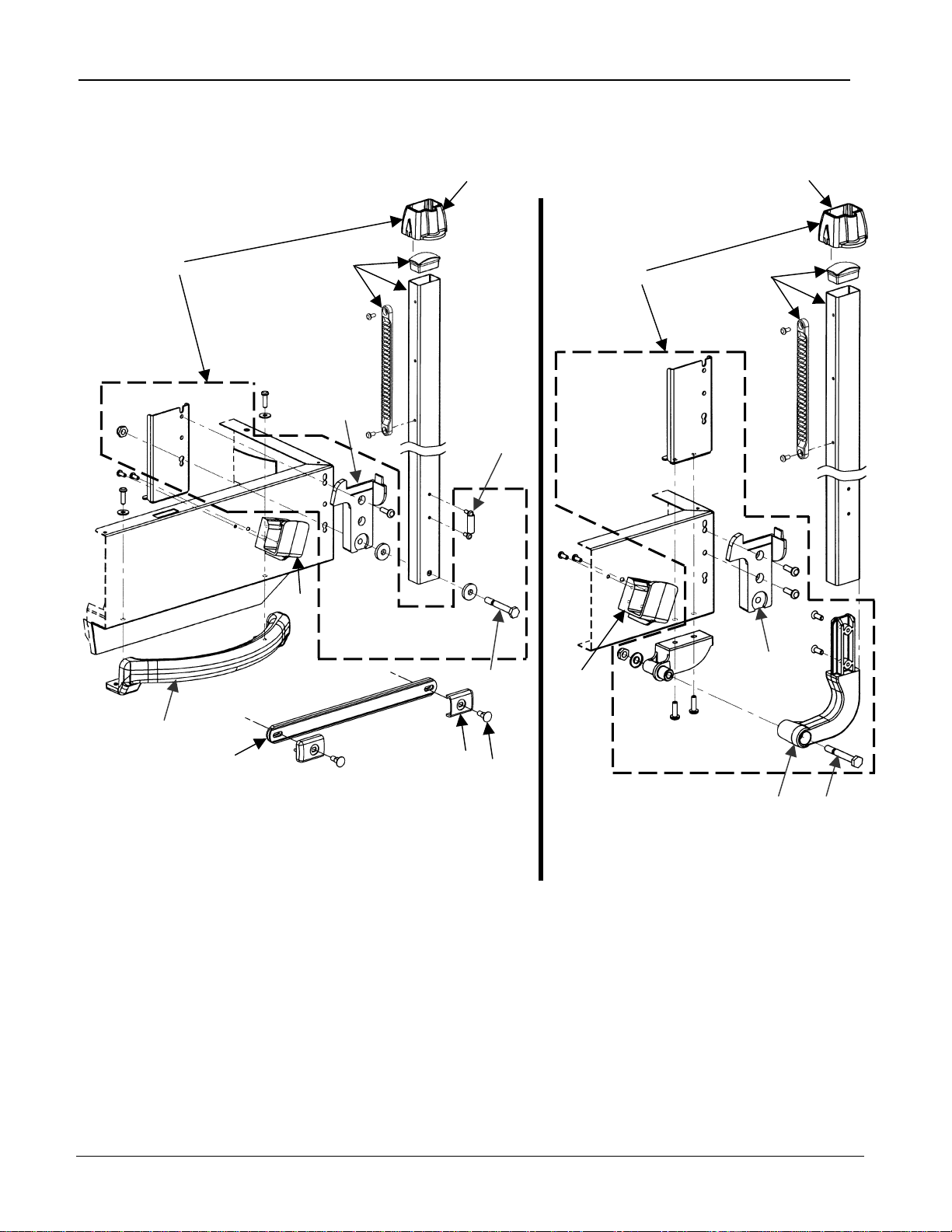
3M™ Overhead Projector 1800 Illustrated Parts Breakdown
Section 6. Post Mounting Hardware
1 2
6
8
5
3
7
5
4
14
9
10
Basic (Post Mounting Hardware) Inverted (Post Mounting Hardware)
Note: Screws, nuts, bolts, clips, and other small hardware
are also contained in the Hardware Kit: P/N 78-8120-8523-7
(Refer to Section 22).
11
12
6
8
13 14
© 3M 2004 12

3M™ Overhead Projector 1800 Illustrated Parts Breakdown
Post Mounting Parts List
Item 3M Part Number Description Qty.
1 78-8120-8516-1 Post Pivot Kit 1
2 78-8120-8514-6 Post, Basic Arm (includes focus rack and cap) 1
3 78-8120-8515-3 Offset Post Pivot Kit 1
4 78-8120-8513-8 Post, Inverted Arm (includes focus rack and cap) 1
5 78-8120-3108-2 Latch, Red 1
6 78-8120-3104-1 Block, Post Mount 1
7 78-8079-8997-1 Screw, Post Latch, Spring 1
8 78-8120-3144-7 Cradle, Post 1
9 78-8120-3126-4 Handle, Carry 1
10 78-8079-9218-1 Strap, Handle (Alternate) 1
11 78-8079-9217-3 Cap, End 2
12 - - - Screw, End Cap 2
13 78-8120-4072-9 Pivot, Post, Offset 1
14 - - - Bolt, Pivot 1
© 3M 2004 13
 Loading...