

Page 1
1700 Overhead Projector
Illustrated Parts Breakdown
Beige colored machines:
1706, 1707, 1710, 1715
Gray colored machines:
1711, 1720, 1730, 1740, 1745, 1760,
1765, 1780
(4/10/2005)
3M Visual Systems Department OHP Service Documentation Resource
6801 River Place Boulevard Copyright © 2005. All Rights Reserved
Austin, Texas 78726-9000 78-6970-7536-0
www.3m.com/meetings
Page 2
3M™ Overhead Projector 1700 Series Illustrated Parts Breakdown
Revision History
Original Issue date: 1998
The release date, revision level, pages changed and a description of the modifications are listed below.
Revision Date Page(s) Changed Description
Rev A 1998 All pages First edition released.
Rev B 4/2001 All pages Added Gray machine references
Rev C 10/2001 Figure 5, Pages 13-14 Top Cover individual parts combined.
Rev D 5/2002
Rev E 9/2002
Rev F 4/2003
Rev G 3/2005
All rights reserved. No part of this book covered by the copyrights hereon may be reproduced or copied in any
form or by any means-graphic, electronic, or mechanical, including photocopying, taping or information storage
and retrieval systems-without written permission of 3M Visual Systems Department.
All pages Updated part nbrs and assembly nbrs. Added
rev history page.
Quick Ref Parts Index
and Figure 1,
Pages 5 and 6
Figure 11, Page 25
Figure 3,
Page 10
All pages Added new Arm/ Focus, Top Cover
Added new Head Assemblies for Gray
machines.
Removed Head Assembly part nbrs for Beige
machines.
Added new Roll Film Kit.
Updated part numbers for items 3 and 10.
Assemblies. Updated kits, part nbrs, and
Appendix information.
© 3M 2005. All Rights Reserved. ii
Page 3

3M™ Overhead Projector 1700 Series Illustrated Parts Breakdown
Table of Contents
INTRODUCTION ...................................................................................................................................................1
QUICK REFERENCE PARTS INDEX .............................................................................................................................2
SECTION 0. MACHINE OVERVIEW.............................................................................................................................3
SECTION 1. HEAD ASSEMBLY..................................................................................................................................4
SECTION 2. ARM AND FOCUS ASSEMBLY (BEIGE COLOR).........................................................................................6
SECTION 3. ARM AND FOCUS ASSEMBLY (GRAY COLOR) (SERIAL NUMBER 170006497 AND BELOW) .........................8
SECTION 4. ARM/FOCUS/POST ASSEMBLY (GRAY COLOR) (SERIAL NUMBER 170006498 AND ABOVE).....................10
SECTION 5. POST ASSEMBLY ................................................................................................................................11
SECTION 6. TOP COVER ASSEMBLY (SERIAL NUMBER 170000988 AND BELOW)......................................................13
SECTION 7. TOP COVER ASSEMBLY (SERIAL NUMBER 170000989 AND ABOVE)......................................................15
SECTION 8. BASE ENCLOSURE..............................................................................................................................16
SECTION 9. CONTROL MODULE .............................................................................................................................18
SECTION 10. LAMP HOUSING (SINGLE)..................................................................................................................20
SECTION 11. LAMP HOUSING (DUAL).....................................................................................................................22
SECTION 12. COOLING FAN...................................................................................................................................24
SECTION 13. ACCESSORIES ..................................................................................................................................26
SECTION 14. WIRE JUMPERS ................................................................................................................................27
SECTION 15. HARDWARE KIT (NO PICTURE)..........................................................................................................29
APPENDIX A – 1700 SPECIFICATIONS.............................................................................................................30
© 3M 2005. All Rights Reserved. iii
Page 4

3M™ Overhead Projector 1700 Series Illustrated Parts Breakdown
This page is intentionally blank
© 3M 2005. All Rights Reserved. iv
Page 5
3M™ Overhead Projector 1700 Series Illustrated Parts Breakdown
rDig
r
Apr
p
r
A
Apr
p
INTRODUCTION
This Illustrated Parts Breakdown (IPB) Manual contains the information necessary to locate and identify
assemblies, sub-assemblies, and specific parts of the 1700 Overhead Projector.
Part Numbers
All components available on a replacement basis are listed with their 3M identification number. The parts
identification list opposite each illustration provides the description adequate to identify components. If the
component is available only as part of the next higher assembly, the description column provides the next
higher assembly description or identification number.
Locating and Identifying a Part
If physical appearance and general location of an item are known:
1. Use the IPB Section Titles to help determine which assembly or sub-assembly includes the item.
2. Refer to the view for the assembly or sub-assembly and locate the item on the exploded view. Match the
part callout number to the corresponding number in the parts list.
3. Parts shown inside a dashed box can only be ordered as an assembly. Any part or mounting hardware
shown outside the box is not included with the assembly.
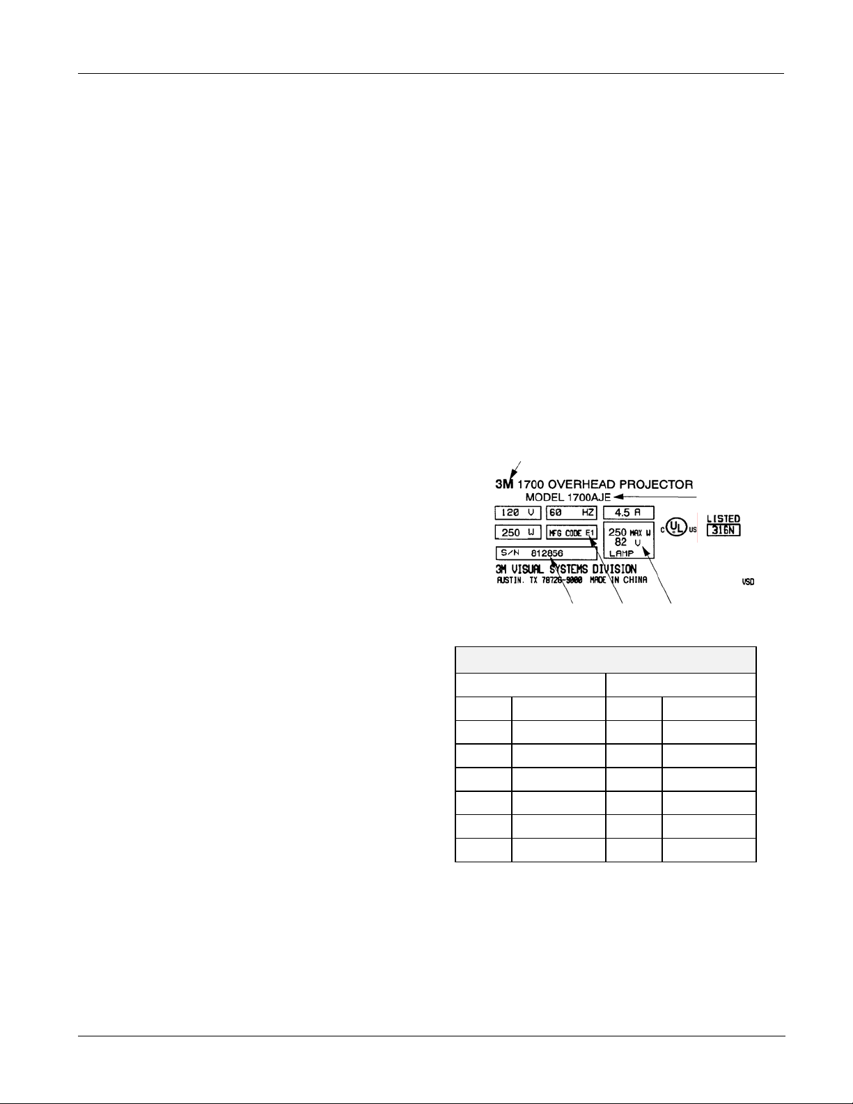
Machine Identification Plate
The serial number plate for the 1700 is located on the
inside wall of the projector. The Machine Identification
Plate is divided into the following components:
1. Product Name: The specific version number of the
projector.
2. Model Number/Alpha Code: The series number of the
projector followed by a three or four character alpha
code identifier. The Alpha Code indicates the design
level, specific product characteristics, power cord or
distribution specific to a country.
3. Lamp: The electrical rating of the lamp.
4. MFG Code: The MFG Code indicates the year and
quarter the projector was built. (See the example to
the right):
5. S/N: The serial number assigned to this projector.
Ordering Parts
When ordering parts, include the following
information:
1. Machine model number and serial number.
2. Parts identification number.
3. Part description.
4. Quantity required.
For U.S. retail customers: Call 1-800-650-8429, or fax 1-800-650-9268. Dealers: Refer to Dealers Guide.
3M Subsidiaries: Contact Export Operations.
E 1997 1 Jan-Ma
F 1998 2
H 1999 3 Jul-Se
J 2000 4 Oct-Dec
K 2001 1 Jan-Ma
C 2005 3 Jul-Se
1
MFG Code
Lette
2004 2
2
5 4 3
it
-Jun
-Jun
© 3M 2005. All Rights Reserved. 1
Page 6
3M™ Overhead Projector 1700 Series Illustrated Parts Breakdown
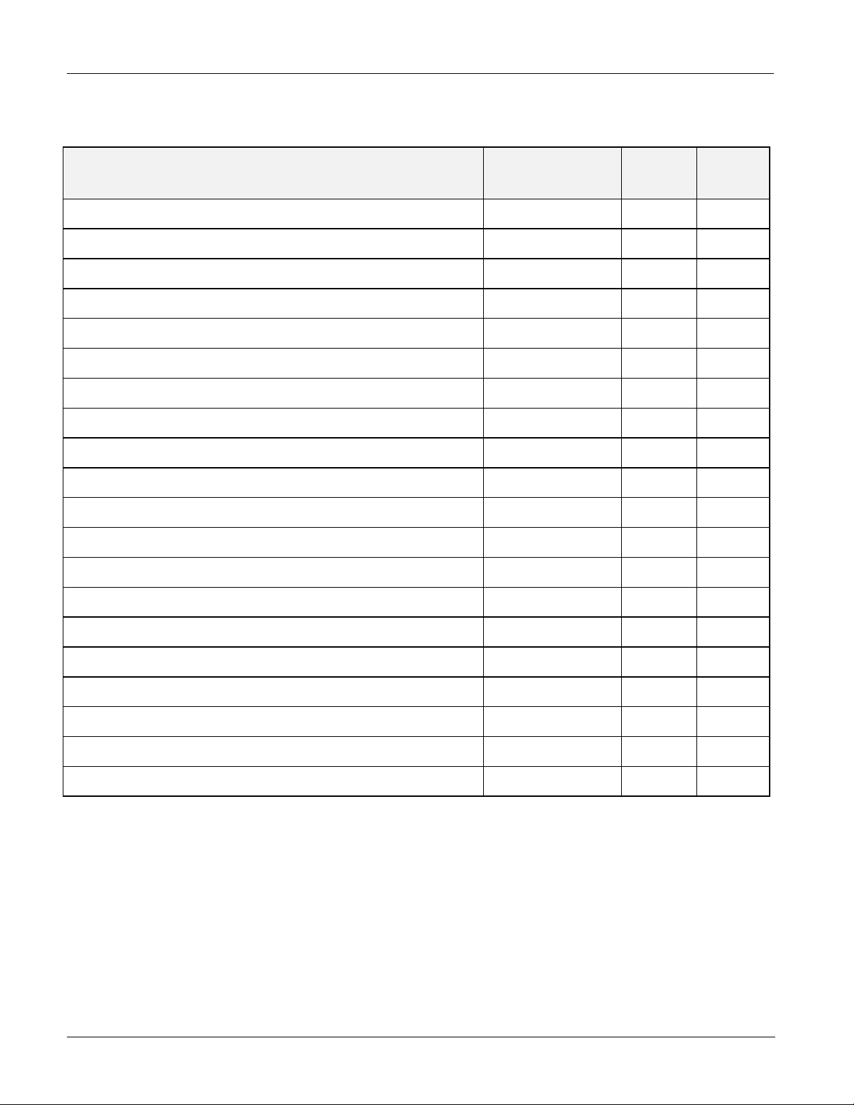
Quick Reference Parts Index
Description Part
Number
Blade, Fan 78-8054-1823-9 12 1
Diode Kit, Inline 78-8054-1836-1 12 8A
Fresnel Lens, Dual-Element XO-0038-0820-1 7 3
Fuse, 5 Amp, 5x20mm (Brazil only) 26-1005-9599-5 12 3
Singlet Head Assembly (1720, 1760, 1765 Gray color) 78-8120-8554-2 1 8A
Doublet Head Assembly (1730, 1780 Gray color) 78-8120-8555-9 1 8B
Open Head Assembly (1711, 1740, 1745 Gray color) 78-8120-8556-7 1 9
Lamp, Projection, ENX, 82V (Single) 78-8011-1186-1 10 3
Lamp, Projection, ENX, 82V (Dual) 78-8011-1186-1 11 4A
Lamp, Projection, FXL, 82V (1745 and 1765) 78-8073-7100-6 11 4B
Motor, Fan, 120V 78-8120-2914-4 12 7
Power Cord, 10 ft., 120V 78-8079-8822-1 8 4A
Section
No.
Item
No.
Resistor, 1.2 Ohm, 0.25 tab 78-8073-7127-9 9, 10 5A, 13
Socket, Single Lamp, ENX 78-8079-8820-5 10 2
Socket, Dual Lamp, Black 78-8073-3017-6 11 3
Thermostat, Safety (ENX) 78-8079-8872-6 10 7
Top Cover Assembly, Single (Beige color) 78-8114-9027-1 6 1A
Top Cover Assembly, Dual (Beige color) 78-8114-9021-4 6 1B
Top Cover Assembly, Basic (Gray color) 78-8120-8572-4 7 1A
Top Cover Assembly, Lamp Changer (Gray color) 78-8120-8573-2 7 1B
IMPORTANT NOTICE
3M reserves the right to sell or furnish NEW OR RECONDITIONED PARTS.
New and reconditioned parts are covered by the same 3M new parts limited warranty.
© 3M 2005. All Rights Reserved. 2
Page 7
3M™ Overhead Projector 1700 Series Illustrated Parts Breakdown
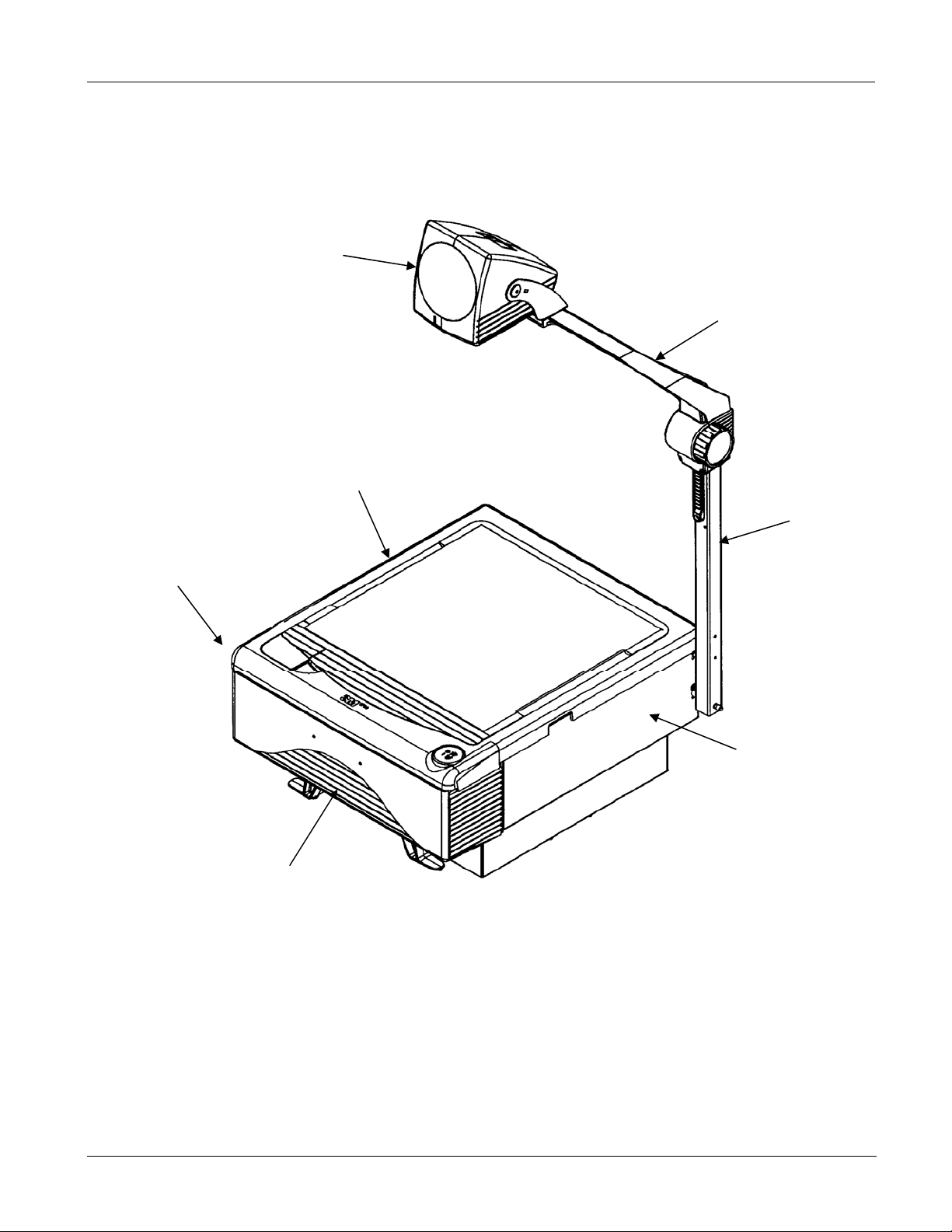
Section 0. Machine Overview
Head Assembly
(See Section 1)
Arm and Focus Assembly
(See Sections 2, 3 and 4)
Top Cover Assembly
(See Sections 6 and 7)
Control Module
(See Section 9)
Post
Assembly
(See
Section 5)
Base Enclosure
(See Section 8)
Lamp Housing (Single)
© 3M 2005. All Rights Reserved. 3
(See Section 10)
Lamp Housing (Dual)
(See Section 11)
Cooling Fan
(See Section 12)
Accessories
(See Section 13)
Wire Jumpers
(See Section 14)
Hardware Kit
(See Section 15)
Page 8
3M™ Overhead Projector 1700 Series Illustrated Parts Breakdown
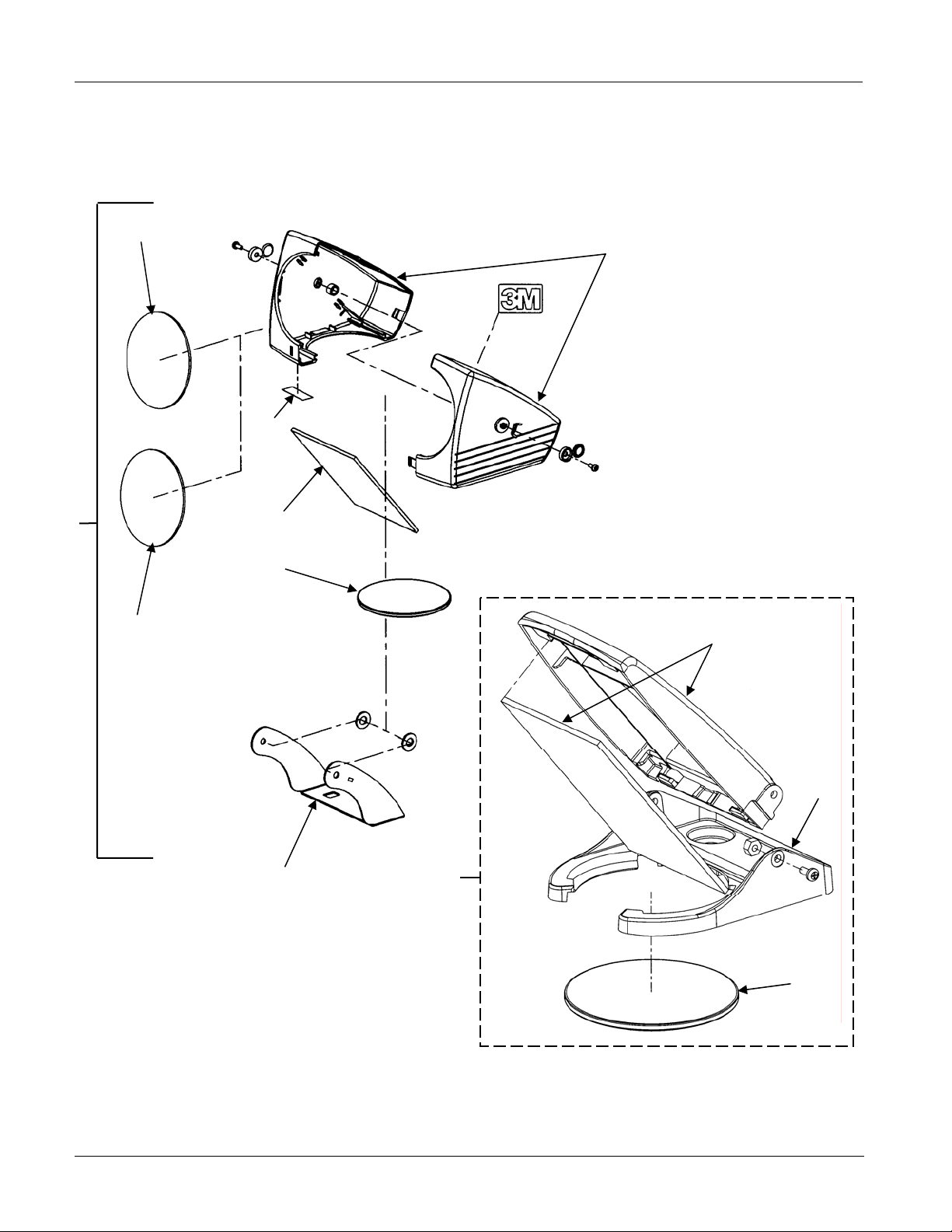
Section 1. Head Assembly
1
2
Closed Head
5
8
4
1, 3
6
Open Head
10
11
7
9
NOTE:
Screws, nuts, bolts, clips, and other small
hardware are contained in the Hardware Kit:
78-8114-9023-0 (See Section 15).
© 3M 2005. All Rights Reserved. 4
3
Page 9
3M™ Overhead Projector 1700 Series Illustrated Parts Breakdown
Head Assembly Parts List
Item
No.
1 78-8114-8795-4 Lens, Doublet Element 2
2A 78-8120-2934-2 Head Halves, Singlet (Beige color) 1
2B 78-8120-2935-9 Head Halves, Doublet (Beige color) 1
2C 78-8120-8451-1 Head Halves, Singlet (Gray color) 1
2D 78-8120-8464-4 Head Halves, Doublet (Gray color) 1
3 78-8014-8951-5 Lens, Wide Angle, 293mm (Singlet Head only) 1
4 78-8114-8812-7 Mirror 1
5 78-8120-3192-6 Label, Head 1
6 78-8120-2927-6 Lens, Head 1
7 78-8120-3072-0 Bracket, Head Mount, Closed Singlet (Gray color only) 1
8A 78-8120-8554-2 Singlet Head Assembly (1720, 1760, 1765 Gray color) 1
8B 78-8120-8555-9 Doublet Head Assembly (1730, 1780 Gray color) 1
3M
Part Number
Description Qty.
9 78-8120-8556-7 Open Head Assembly (1711, 1740, 1745 Gray color) 1
10 78-8120-8501-3 Open Singlet Mirror Assembly 1
11 (Not available) Housing, Lens, Split, Open Singlet 1
© 3M 2005. All Rights Reserved. 5
Page 10
3M™ Overhead Projector 1700 Series Illustrated Parts Breakdown
Section 2. Arm and Focus Assembly (Beige color)
1
2
12
11
9
6
NOTE:
Screws, nuts, bolts, clips, and other small
hardware are contained in the Hardware Kit:
78-8114-9023-0 (See Section 15).
7, 8
10
4
5
3
See Section 5
© 3M 2005. All Rights Reserved. 6
Page 11
3M™ Overhead Projector 1700 Series Illustrated Parts Breakdown
Arm and Focus Assembly (Beige color) Parts List
Item
No.
1 78-8114-8983-6 Shim, Head Leveling 1
2 78-8073-3035-8 Arm, Focus 1
3 78-8120-2920-1 Plate, Standoff 1
4 78-8120-2925-0 Pad, Wear 2
5 78-8064-1601-8 Knob, Focus 1
6 78-8073-3041-6 Cap, Focus Arm 1
7 78-8079-8745-4 Gear, Focus 1
8 26(Not available) Lubricant, Nye Rheolube 368 AR
9 78-8079-8747-0 Bar, Pressure 1
10 78-8079-8743-9 Clamp, Friction 1
11 78-8079-8744-7 Rack, Focus 1
12 26-1009-3653-8 Cap, Post 1
3M
Part Number
Description Qty.
© 3M 2005. All Rights Reserved. 7
Page 12

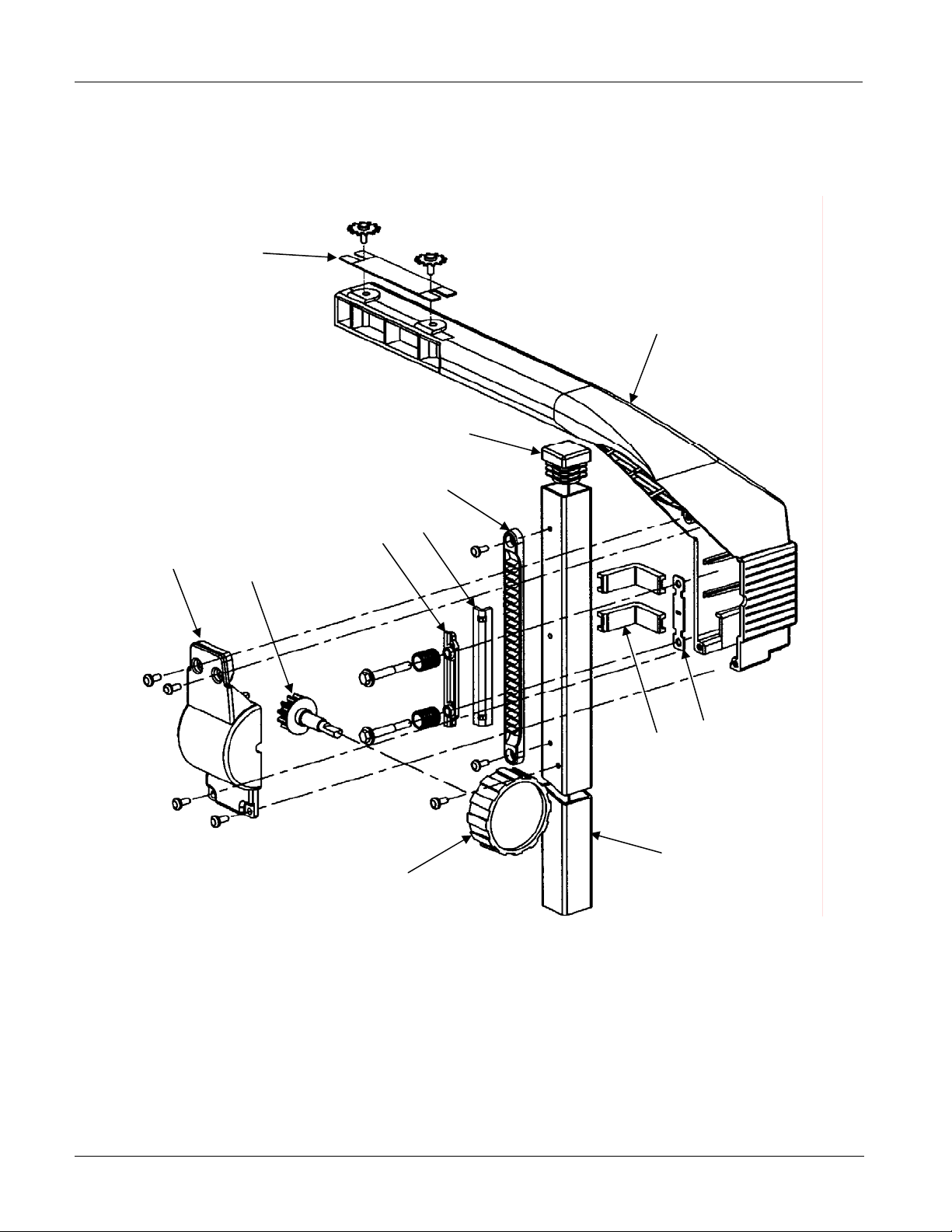
3M™ Overhead Projector 1700 Series Illustrated Parts Breakdown
Section 3. Arm and Focus Assembly (Gray color)
(Serial Number 170006497 and below)
1
7
9
8
3
4
5
6
See Section 5
10
2
NOTE:
Screws, nuts, bolts, clips, and other small
hardware are contained in the Hardware Kit:
78-8114-9023-0 (See Section 15).
© 3M 2005. All Rights Reserved. 8
Page 13

3M™ Overhead Projector 1700 Series Illustrated Parts Breakdown
Arm and Focus Assembly (Gray color) Parts List
(Serial Number 170006497 and below)
Item
No.
1 78-8114-8983-6 Shim, Head Leveling 1
2 78-8120-3045-6 Arm, Focus 1
3 (Not Available) Spring, Leaf 1
4 78-8120-3069-6 Pad, Rear 1
5 78-8120-3047-2 Pad, Friction, Lower 1
6 78-8120-3048-0 Knob, Gear, Focus 1
7 78-8120-3046-4 Cap, Focus Arm 1
8 78-8079-8744-7 Rack, Focus 1
9 26-1009-3653-8 Cap, Post 1
10 78-8120-4017-4 Pad, Friction. Upper 1
3M
Part Number
Description Qty.
© 3M 2005. All Rights Reserved. 9
Page 14

3M™ Overhead Projector 1700 Series Illustrated Parts Breakdown
Section 4. Arm/Focus/Post Assembly (Gray color)
(Serial Number 170006498 and above)
1
NOTE:
Screws, nuts,
bolts, clips, and
other small
hardware are
contained in the
Hardware Kit:
78-8114-9023-0
(See Section 15).
Parts List (Serial Number 170006498 and above)
Item
No.
1 XO-0038-0891-2 Focus Arm Kit 1
3M
Part Number
Description Qty.
© 3M 2005. All Rights Reserved. 10
Page 15

3M™ Overhead Projector 1700 Series Illustrated Parts Breakdown
Section 5. Post Assembly
1
Fixed Post
4
2
5
Folding Post
11
3
6
7
8
NOTE:
Screws, nuts, bolts, clips, and other small
hardware are contained in the Hardware Kit:
78-8114-9023-0 (See Section 15).
© 3M 2005. All Rights Reserved. 11
10
9
Page 16

3M™ Overhead Projector 1700 Series Illustrated Parts Breakdown
Post Assembly Parts List
Item
No.
1A (Not available) Post (Beige color) 1
1B (Not available) Post, Fixed, Offset Rack (Gray color) 1
2 78-8079-8811-4 Bolt, Post 2
3 78-8096-5804-6 Wrench 1
4 78-8079-8810-6 Bracket, Backup 1
5 78-8079-8809-8 Block, Post 1
6 (Not available) Post, Folding 1
7 (Not available) Spring, Compression 1
8 78-8079-8852-8 Lock, Post 1
9 78-8079-8875-9 Mount, Post, Pivot 1
10 78-8079-8850-2 Bolt, Pivot 1
11 78-8079-8846-0 Bracket, Pivot 1
3M
Part Number
Description Qty.
© 3M 2005. All Rights Reserved. 12
Page 17

3M™ Overhead Projector 1700 Series Illustrated Parts Breakdown
Section 6. Top Cover Assembly
(Serial Number 170000988 and below)
4
1
3
2
NOTE:
Screws, nuts, bolts, clips, and other small hardware are contained in the Hardware Kit:
78-8114-9023-0 (See Section 15).
© 3M 2005. All Rights Reserved. 13
Page 18

3M™ Overhead Projector 1700 Series Illustrated Parts Breakdown
Top Cover Assembly Parts List
(Serial Number 170000988 and below)
Item
No.
1A 78-8114-9027-1 Top Cover Assembly, Single (Beige color) 1
1B 78-8114-9021-4 Top Cover Assembly, Dual (Beige color) 1
2 (Reference only) Fresnel Lens (See note below) 1
3 78-8120-2941-7 Bracket, Hinge 1
4 78-8064-1515-0 Actuator Switch 1
3M
Part Number
Description Qty.
NOTE:
If the machine currently has a single-element fresnel lens and a new fresnel is needed, two options are
available:
1. Replace the top cover with the appropriate assembly listed in Section 7.
2. Install Kit #78-8121-4740-9. This kit adapts single-element top covers to accept a dual-element
fresnel lens.
Refer to Technical Bulletin #10 for additional information.
© 3M 2005. All Rights Reserved. 14
Page 19

3M™ Overhead Projector 1700 Series Illustrated Parts Breakdown
Section 7. Top Cover Assembly
(Serial Number 170000989 and above)
2
1
NOTE:
Screws, nuts, bolts,
clips, and other small
3
hardware are
contained in the
Hardware Kit:
78-8114-9023-0
(See Section 15).
Top Cover Assembly Parts List
(Serial Number 170000989 and above)
Item
No.
1A 78-8120-8572-4 Top Cover Assembly (Basic - Gray color) 1
1B 78-8120-8573-2 Top Cover Assembly (Lamp Changer - Gray color) 1
2 78-8120-4156-0 Stage Glass 1
3 XO-0038-0820-1 Fresnel Lens, Dual-Element 1
3M
Part Number
Description Qty.
4 78-8064-1515-0 Actuator Switch 1
© 3M 2005. All Rights Reserved. 15
Page 20

3M™ Overhead Projector 1700 Series Illustrated Parts Breakdown
,
Section 8. Base Enclosure
1
9
8
6
7
5
8
2
3
4
NOTE:
Screws, nuts, bolts, clips, and other small hardware are contained in the Hardware Kit:
78-8114-9023-0 (See Section 15).
© 3M 2005. All Rights Reserved. 16
Page 21

3M™ Overhead Projector 1700 Series Illustrated Parts Breakdown
Base Enclosure Parts List
Item
No.
1 78-8079-9141-5 Body Mirror Assembly 1
2A (Not available) Base, Fixed Post (Beige color) 1
2B (Not available) Base, Fixed Post (Gray color) 1
2C (Not available) Base, Folding Post 1
3 DY-1160-2020-6 Strain Relief 1
4A 78-8079-8822-1 Power Cord, 10 ft., 120V 1
4B (Not available) Power Cord, 2 Blade with ground, 127V (Brazil) 1
5 26-1008-5211-5 Foot, Mounting 4
6 78-8073-3039-0 Switch, Interlock Switch 1
7 (Not available) Cover, Interlock Switch 1
8 78-8079-8817-1 Pivot, Cover 2
9 (Not available) Clip/Clamp, 0.310 max bundle dia. 1
3M
Part Number
Description Qty.
© 3M 2005. All Rights Reserved. 17
Page 22

3M™ Overhead Projector 1700 Series Illustrated Parts Breakdown
Section 9. Control Module
1
2
9
8
3
7
4
6
5
NOTE:
Screws, nuts, bolts, clips, and other small hardware are contained in the Hardware Kit:
78-8114-9023-0 (See Section 15).
© 3M 2005. All Rights Reserved. 18
Page 23

3M™ Overhead Projector 1700 Series Illustrated Parts Breakdown
Control Module Parts List
Item
No.
1 78-8073-2962-4 Knob, Lamp Changer 1
2A 78-8073-2963-2 Housing, Lamp Changer (1 Hole) 1
2B (Not available) Housing, Lamp Changer 1
3 78-8073-2961-6 Bracket, Lamp Changer 1
4A 78-8073-3012-7 Cover, Resistor, 20W 1
4B (Not available) Bracket, Resistor, 40W 1
5A 78-8073-7127-9 Resistor, 1.2 Ohm, 0.25 tab 1
5B (Not available) Resistor, 2.2 Ohm, 0.25 tab 1
6 12-7995-0850-7 Spring, Extension 1
7 78-8079-8881-7 Lever, Lamp Changer 1
8 78-8079-8933-6 Thermostat 1
9 78-8079-8855-1 Switch, Lamp Changer/Dimmer 2
3M
Part Number
Description Qty.
10 78-8114-9017-2 Control Module (entire assembly) 1
© 3M 2005. All Rights Reserved. 19
Page 24

3M™ Overhead Projector 1700 Series Illustrated Parts Breakdown
Section 10. Lamp Housing (Single)
14
13
2
1
3
4
5
6
7
8
12
9
10
11
NOTE:
Screws, nuts, bolts, clips, and other small hardware are contained in the Hardware Kit:
78-8114-9023-0 (See Section 15).
© 3M 2005. All Rights Reserved. 20
Page 25

3M™ Overhead Projector 1700 Series Illustrated Parts Breakdown
Lamp Housing (Single) Parts List
Item
No.
1 78-8064-1509-3 Cover, Wire 1
2 78-8079-8820-5 Socket, Single Lamp, ENX 1
3 78-8011-1186-1 Lamp, Projection, ENX, 82V 1
4 78-8064-1491-4 Ejector, Lamp 1
5 78-8064-1510-1 Spring, Lamp, Retaining 1
6 78-8073-7208-7 Bracket, Socket 1
7 78-8079-8872-6 Thermostat, Safety (ENX) 1
8 78-8079-8895-7 Mount, Single Lamp, ENX 1
9 (Not available) Resistor, 2.2 Ohm, 0.25 tab 1
10 78-8120-2913-6 Bracket, Motor 1
11A 78-8114-9019-8 Housing, Lamp (Beige color) 1
11B 78-8120-8458-6 Housing, Lamp (Gray color) 1
3M
Part Number
Description Qty.
12 (Not available) Clip, Resistor, 40W 1
13 78-8073-7127-9 Resistor, 1.2 Ohm, 0.25 tab 1
14 78-8079-8840-3 Bracket, Support 1
© 3M 2005. All Rights Reserved. 21
Page 26

3M™ Overhead Projector 1700 Series Illustrated Parts Breakdown
Section 11. Lamp Housing (Dual)
3
1
21
20
19
2
4
5
Control Module
(See Section 9)
18
17
16
15
6
8
7
9
10
11
12
13
14
NOTE:
Screws, nuts, bolts, clips, and other small hardware are contained in the Hardware Kit:
78-8114-9023-0 (See Section 15).
© 3M 2005. All Rights Reserved. 22
Page 27

3M™ Overhead Projector 1700 Series Illustrated Parts Breakdown
Lamp Housing (Dual) Parts List
Item
No.
1 78-8079-8887-4 Rod, Lamp Changer 1
2 78-8079-8984-9 Sleeve, Insulator 1
3 78-8073-3017-6 Socket, Dual Lamp, Black 1
4A 78-8011-1186-1 Lamp, Projection, ENX, 82V 1
4B 78-8073-7100-6 Lamp, Projection, FXL, 82V (1745 and 1765) 1
5 78-8079-8863-5 Retainer, Lamp 2
6 (Not available) Plate, Dual Lamp, ENX 1
7 78-8079-8862-7 Ejector, Lamp 1
8 (Not available) Pivot, Dual Lamp Mount, ENX 1
9 (Not Available) Bracket, Lamp Mount, ENX 1
10 26-1009-7186-5 Clip, Shaft, Color Tuning 1
11 26-1009-7485-1 Spring, Compression 1
3M
Part Number
Description Qty.
12 78-8079-8912-0 Knob, Color Tuning 1
13 78-8120-2913-6 Bracket, Motor 1
14A 78-8114-9019-8 Housing, Lamp (Beige color) 1
14B 78-8120-8458-6 Housing, Lamp (Gray color) 1
15 (Not available) Tape, Reflective, #7323, 3” x 60 yards 1
16 78-8079-8893-2 Shaft, Color Tuning 1
17 (Not Available) Clip/Clamp, Cable 2
18 (Not Available) Sleeve, Color Tuning 1
19 78-8079-8858-5 Plate, Dual Socket, ENX 1
20 78-8079-8923-7 Bracket, Wire Cover 1
21 78-8114-9020-6 Dual Lamp Assembly (Items 1,2,3,5,6,7,8,18,20)
© 3M 2005. All Rights Reserved. 23
Page 28

3M™ Overhead Projector 1700 Series Illustrated Parts Breakdown
Section 12. Cooling Fan
1
2
Brazil Models
Only
12
11
3
4
6
8
5
7
10
NOTE:
Screws, nuts, bolts, clips, and other small hardware are contained in the Hardware Kit:
78-8114-9023-0 (See Section 15).
© 3M 2005. All Rights Reserved. 24
9
Page 29

3M™ Overhead Projector 1700 Series Illustrated Parts Breakdown
Cooling Fan Parts List
Item
No.
1 78-8054-1823-9 Blade, Fan 1
2A (Not available as
2B (Not available as
3 26-1005-9599-5 Fuse, 5 Amp, 5x20mm, Slow Acting (Brazil only) 1
4 26-1005-6624-4 Fuseholder, Block 1
5 78-8079-8873-4 Duct, Fan, Rear 1
6 78-8079-8874-2 Duct, Fan, Front 1
7 78-8120-2914-4 Motor, Fan, 120V 1
8A 78-8054-1836-1 Diode Kit, Inline 1
8B (Not available) Diode Kit, Inline (Brazil) 1
9 78-8079-8797-5 Plate, Cord 1
3M
Part Number
separate item)
separate item)
Description Qty.
Switch (all models except 1707 AAFB, 1710 AABB,
1720 AACB, and 1760 AANB)
Switch (Models 1707 AAFB, 1710 AABB, 1720 AACB,
and 1760 AANB)
1
1
10 (Not available) Data Nameplate 1
11A 78-8120-2913-6 Bracket, Motor 1
11B (Not available) Bracket, Motor (Brazil) 1
12 78-8114-9015-6 Motor Fan Assembly (Items 1, 2, 5, 6, 7, 11) 1
© 3M 2005. All Rights Reserved. 25
Page 30

3M™ Overhead Projector 1700 Series Illustrated Parts Breakdown
Section 13. Accessories
Roller Kit
Side-to-Side Installation
1
Front-to-Rear Installation
Roller Kit
1
2
Accessories Parts List
Item
No.
1 XO-0038-0750-0 Kit, Roll Film, 10-1/4 inch (260.4mm) (Complete assembly) 1
2 XO-0038-0751-8 Film, Roll, 10-1/4 inch (260.4mm) 1
3 78-6969-7216-1 Dust Cover (Not shown) (Fits all projectors, including those
3M
Part Number
Description Qty.
1
with Roller Kits)
© 3M 2005. All Rights Reserved. 26
Page 31

3M™ Overhead Projector 1700 Series Illustrated Parts Breakdown
Section 14. Wire Jumpers
1707 ENX
(Brazil)
1710 ENX
(Brazil)
4
4
6 7
9 10
1706/1707 ENX
U.S/Canada/Mexico
1710/1715 ENX
U.S./Canada/Mexico
© 3M 2005. All Rights Reserved. 27
Page 32

3M™ Overhead Projector 1700 Series Illustrated Parts Breakdown
Wire Jumpers Parts List
Item
No.
1 (Not available) Jumper, 12.5 in., Black (Interlock – On/Off) 1
2 (Not available) Jumper, 33 in. 1
3 (Not available) Jumper, Power Switch to Power Supply 1
4 (Not available) Jumper, 9 in., White 1
5 (Not available) Jumper, 12.5, White 1
6 (Not available) Jumper, 12 in. 1
7 (Not available) Jumper, 5.5 in., Black 1
8 (Not available) Jumper, 22 in., Insulated 1
9 (Not available) Jumper, 8.75 in. 1
10 (Not available) Jumper, 3.5 in., Brown, Insulated 1
11 (Not available) Jumper, Ground, 18 in., Green/Yellow (Not shown) 1
12 (Not available) Jumper, 10 in., Black (Switch/Fuse) (Not shown) 1
3M
Part Number
Description Qty.
© 3M 2005. All Rights Reserved. 28
Page 33

3M™ Overhead Projector 1700 Series Illustrated Parts Breakdown
Section 15. Hardware Kit (No Picture)
Item
No.
0 78-8114-9023-0 Hardware Kit 1
3M
Part Number
Description Qty.
© 3M 2005. All Rights Reserved. 29
Page 34

3M™ Overhead Projector 1700 Series Illustrated Parts Breakdown
APPENDIX A – 1700 SPECIFICATIONS
Country
Power Cord
Current Models
United
States
United
States
United
States
United
States
United
States
United
States
Discontinued Models
United
States
United
States
Mexico B 1707 AAFM 78-9236-6309-6 127/60 NOM 10 in.
United
States
United
States
Mexico B 1710 AABM 78-9236-6312-0 127/60 NOM 10 in.
United
States
United
States
United
States
B 1711 BJA XO-0038-0800-3 120/60 UL / cUL 10 in.
B 1720 BJV XO-0038-0801-1 120/60 UL / cUL 10 in.
B 1730 AJP XO-0038-0808-6 120/60 UL / cUL 10 in.
B 1740 AJZ XO-0038-0803-7 120/60 UL / cUL 10 in.
B 1760 BJC XO-0038-0802-9 120/60 UL / cUL
B 1780 AJK XO-0038-0806-0 120/60 UL / cUL 10 in.
B 1706 AJE 78-9236-6307-0 120/60 UL / cUL 10 in.
B 1706 AKE 78-9236-6308-8 120/60 UL / cUL 10 in.
B 1707 AJF 78-9236-6310-4 120/60 UL / cUL 10 in.
B 1707 AKF 78-9236-6311-2 120/60 UL / cUL 10 in.
B 1710 AJB 78-9236-6313-8 120/60 UL / cUL 10 in.
B 1710 AKB 78-9236-6314-6 120/60 UL / cUL 10 in.
B 1715 AJG 78-9236-6315-3 120/60 UL / cUL 10 in.
Alpha
Stock Number
Voltage
Agency
Stage
10 in.
Head
Open
Singlet
Closed
Singlet
Closed
Doublet
Open
Singlet
Closed
Singlet
Closed
Doublet
Closed
Doublet
Closed
Doublet
Closed
Singlet
Closed
Singlet
Closed
Singlet
Closed
Singlet
Closed
Singlet
Closed
Singlet
Closed
Doublet
Handle
N Internal Fixed ENX N No 1
N Internal Fixed ENX N No 1
N Internal Fixed ENX N No 1
N External Fixed ENX Y No 1
N External Fixed ENX Y No 1
N External Fixed ENX Y No 1
N Internal Fixed ENX N Resistor 1
N Internal Fixed ENX N Resistor 1
N Internal Fixed ENX N Resistor 1
N Internal Fixed ENX N Resistor 1
N Internal Fixed ENX N Resistor 1
N External Fixed ENX Y Resistor 1
N External Fixed ENX Y Resistor 1
N External Fixed ENX Y Resistor 1
N External Fixed ENX Y Resistor 1
Color Tune
Post Type
Lamp
Lamp Changer
Lamp Control
Lamps Installed
Fresnel
Dual
Element
Dual
Element
Dual
Element
Dual
Element
Dual
Element
Dual
Element
Single
Element
Single
Element
Single
Element
Single
Element
Single
Element
Single
Element
Single
Element
Single
Element
Single
Element
Power
Diode No Y
Diode No Y
Diode No Y
Diode No Y
Diode No Y
Diode No Y
Diode No Y
Diode No Y
Diode No Y
Diode No Y
Diode No Y
Diode No Y
Diode No Y
Diode No Y
Diode No Y
Fuse
Cord Storage
© 3M 2005. All Rights Reserved. 30
Page 35

3M™ Overhead Projector 1700 Series Illustrated Parts Breakdown
Discontinued Models (continued)
Country
Power Cord
United
States
Brazil A 1720 AACB 78-9236-6316-4 127/60 - - 10 in.
Mexico B 1720 AACM 78-9236-6312-3 127/60 NOM 10 in.
United
States
Brazil A 1760 AANB 78-9236-6314-9 127/60 - - 10 in.
Mexico B 1760 AANM 78-9236-6315-6 120/60 NOM 10 in.
United
States
B 1715 AKG 78-9236-6350-0 120/60 UL / cUL 10 in.
B 1745 AJM 78-9236-6599-2 120/60 UL / cUL 10 in.
B 1765 AJL 78-9236-6600-8 120/60 UL / cUL 10 in.
Alpha
Stock Number
Voltage
Agency
Stage
Head
Closed
Doublet
Open
Singlet
Closed
Singlet
Open
Singlet
Closed
Singlet
Open
Singlet
Closed
Singlet
Handle
N External Fixed ENX Y Resistor 1
N Internal Fixed ENX N Resistor 1
N Internal Fixed ENX N Resistor 1
N External Folding FXL Y Resistor 1
N External Fixed ENX Y Resistor 1
N External Fixed ENX Y Resistor 1
N External Folding FXL Y Resistor 1
Color Tune
Post Type
Lamp
Lamp Changer
Lamp Control
Lamps Installed
Fresnel
Single
Element
Single
Element
Single
Element
Single
Element
Single
Element
Single
Element
Single
Element
Power
Diode No Y
Diode No Y
Diode No Y
Diode No Y
Diode No Y
Diode No Y
Diode No Y
Fuse
Cord Storage
© 3M 2005. All Rights Reserved. 31
Page 36

3M™ Overhead Projector 1700 Series Illustrated Parts Breakdown
http://www.3M.com/meetings
Important Notice
All statements, technical information, and recommendations related to 3M’s products are based on information believed to be reliable,
but the accuracy or completeness is not guaranteed. Before using this product, you must evaluate it and determine if it is suitable for
your intended application. You assume all risks and liability associated with such use. Any statements related to the product which are
not contained in 3M’s current publications, or any contrary statements contained on your purchase order shall have no force or effect
unless expressly set forth in a written agreement signed by an authorized officer of 3M.
© 3M 2005 32
 Loading...