

Page 1

Instructions and Parts List
Important Safety
Information
BEFORE INSTALLING
™
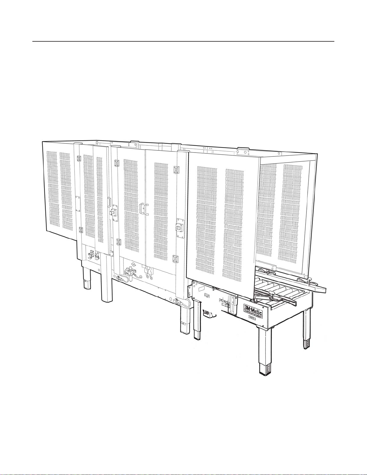
3M-Matic
a80f-if Type 11000
Powered
Infeed
OR OPERATING THIS
EQUIPMENT
Read, understand, and
follow all safety and
operating instructions.
Spare Parts
It is recommended you
immediately order the
Conveyor
Serial No.
For reference, record machine serial number here.
3M Industrial Adhesives and Tapes
3M Center, Building 220-5E-06
St. Paul, MN 55144-1000
spare parts listed in the
"Spare Parts/Service
Information" section.
These parts are expected
to wear through normal
use, and should be kept
on hand to minimize
production delays.
3M-Matic
3M St. Paul, MN 55144-1000
Printed in U.S.A.
© 3M 2011 44-0009-2097-3 (B060311-NA)
TM
and AccuGlideTM are Trademarks of
Page 2

This instruction manual covers safety aspects,
handling and transport, storage, unpacking,
preparation, installation, operation, adjustments,
maintenance, troubleshooting, repair work and
servicing plus parts list of the 3M-MaticTM
a80f-if-NA Infeed Conveyor.
3M Industrial Adhesives and Tapes
3M Center, Building 220-5E-06
St. Paul, MN 55144-1000
Edition June 2011
Copyright 3M 2011
All rights reserved
The manufacturer reserves the right to change
the product at any time without notice.
Page 3

Replacement Parts and Service Information
To Our Customers:
This is the 3M-Matic™ equipment you ordered. It has been set up and tested in the factory.
If technical assistance or replacement parts are needed, call or fax the appropriate number.
Included with each machine is an Instructions and Parts List manual.
Technical Assistance / Replacement Parts and Additional Manuals:
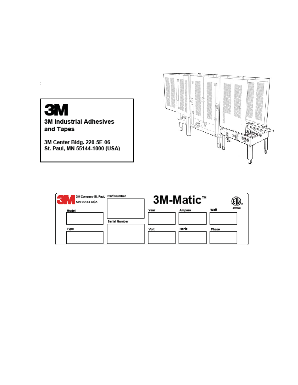
Contact your service provider. Provide the customer support coordinator with the model/machine
name, machine type, and serial number that are located on the identifi cation plate
(For example: Model a80f-if - Type 11000 - Serial Number 13282).
Identifi cation Plate
For Commercial Use Only
3M Industrial Adhesives and Tapes
3M Center, Building 220-5E-06
St. Paul, MN 55144-1000
3M-Matic™, AccuGlide™ and Scotch™ are
Trademarks of
3M St. Paul, MN 55144-1000
Printed in U.S.A.
i
Page 4

THIS PAGE IS BLANK
Page 5

TABLE OF CONTENTS (continued)
a80f-if Infeed Conveyor Page
Cover Page
Table of Contents .................................................................................................................. i - iii
Acronyms and Abbreviations ................................................................................................. iv
1. Introduction
1.1 Manufacturing Specifi cations / Description / Intended Use ........................................... 1
1.2 How to Read and Use the Manual / Reference Documents ........................................... 2
1.2.1 Importance of the Manual ........................................................................................... 2
1.2.2 Manual Maintenance .................................................................................................. 2
1.2.3 Consulting the Manual ................................................................................................. 2
1.2.4 How to Update the Manual in Case of Modifi cations ................................................... 2
2. General Information
2.1 Identifi cation Data .......................................................................................................... 3
2.2 Warranty / Contents ....................................................................................................... 4
3. Safety
3.1 General Safety Information ............................................................................................ 5
3.2 Signal Words Explanation .............................................................................................. 5
3.3 Table of Warnings ................ ........................................................................................... 6 - 7
3.4 Operator's Qualifi cations .............................................................................................. 8
3.5 Number of Operators ...................................................................................................... 8
3.6 Instructions for Safe Use ................................................................................................. 8
3.7 Residual Hazards ............................................................................................................ 8
3.8 Prevent Other Hazards - Recommendations and Measures ......................................... 8
3.9 Personal Safety Measures ............................................................................................. 8
3.10 Incorrect / Predictable Actions Not Allowed ................................................................... 8
3.11 Operator's Skill Required Skill Levels ............................................................................. 9
3.12 Component Locations .................................................................................................... 10
3.13 Table of Warnings and Replacement Labels ................................................................. 11
4. Technical Specifi cations
4.1 Power Requirements ...................................................................................................... 13
4.2 Operating Rate
4.3 Operating Conditions ...................................................................................................... 13
4.4 Box Board ....................................................................................................................... 13
4.5 Box Weight and Size Capacities ..................................................................................... 13
4.6 Machine Dimensions ....................................................................................................... 13
5. Shipment, Handling, and Storage
............................................................................................................... 13
5.1 Packed Machine Shipment and Handling ...................................................................... 15
5.2 Handling and Transportation of Uncrated Machine ........................................................ 15
5.3 Machine Storage ............................................................................................................ 15
a80f-if-NA
ii
5
2011 June
Page 6

THIS PAGE IS BLANK
Page 7

TABLE OF CONTENTS (continued)
6. Unpacking
6.1 Uncrating ............................................................................................................................. 16
6.2 Packaging Materials Disposal ............................................................................................. 16
7. Installation and Operation
7.1 Operating Conditions .......................................................................................................... 17
7.2 Space Requirements for Machine Operation and Maintenance ......................................... 17
7.3 Machine Positioning / Bed Height ........................................................................................ 17
7.4 Preliminary Electric Inspection ............................................................................................ 18
7.5 Main Power Machine Connection and Inspection ............................................................... 18
7.6 Pneumatic Connection ....................................................................................................... 18 - 19
7.7 Infeed Conveyor Assembly ................................................................................................. 19 - 21
8. Maintenance
8.1 Safety Measures (see section 3) ........................................................................................ 22
8.2 Tools and Spare Parts Supplied with Machine ................................................................... 22
8.3 Maintenance Operations - Recommended Inspections and Frequency .............................. 22
8.4 Inspections to be Performed Before and After Every Maintenance Operation .................... 22
8.5 Safety Features (Inspection Effi ciency) .............................................................................. 22
8.6 Machine Cleaning ............................................................................................................... 23
8.7 Lubrication .......................................................................................................................... 23
8.8 Lubrication Products ........................................................................................................... 23
8.9 Maintenance Work Log ....................................................................................................... 24
9. Additional Instructions
9.1 Machine Disposal Information ............................................................................................. 25
9.2 Emergency Procedures ...................................................................................................... 25
10. Special Information
10.1 Statement of Conformity ................................................................................................. 25
10.2 Hazardous Substances Emission ................................................................................... 25
11. Technical Documentation and Information
11.1 Pneumatic Diagrams ....................................................................................................... 26
11.2 Electric Diagrams ............................................................................................................ 27
11.3 Spare Parts / Ordering .................................................................................................... 28 - 29
Drawings and Parts Lists ....................................................................................................... 31 - End of Manual
a80f-if-NA
iii
2011 June
Page 8

ABBREVIA TIONS AND ACRONYMS
LIST OF ABBREVIATIONS, ACRONYMS
3M-Matic - Trademark of 3M St. Paul, MN 55144-1000
AccuGlide - Trademark of 3M St. Paul, MN 55144-1000
Scotch - Trademark of 3M St. Paul, MN 55144-1000
Drw. - drawing
Ex. - for example
Figure - exploded view fi gure no. (spare parts)
Figure - Illustration
Max. - maximum
Min. - minimum
Nr. - number
N/A - not applicable
OFF - machine not operating
ON - machine operating
PLC - Programmable Logic Control
PP - Polypropylene
PU/PU Foam - Polyurethane Foam
PTFE - Polytetrafl ourethelene
PVC - Poly-vinyl chloride
W - Width
H - Height
L - Length
a80f-if-NA
iv
2011 June
Page 9
1-INTRODUCTION
1.1 Manufacturing Specifi cations / Description / Intended Use
TM
The 3M-Matic
a80f-if Infeed Conveyor is designed to automatically gate individual boxes from a fl ooded
incoming line, and is specifi cally for use with the 3M-Matic™ a80f-if. The timer can be set before each
run to adjust for different box lengths.
3M-MaticTM a80f-if Infeed Conveyor, Type 11000
a80f-if-NA
1
2011 June
Page 10

1-INTRODUCTION (continued)
1.2 How to Read and Use the Instruction Manual
This instruction manual covers safety aspects,
handling and transport, storage, unpacking,
preparation, installation, operation, setup and
adjust- ments, technical and manufacturing
specifi cations, maintenance, troubleshooting, repair
work and servicing, electric diagrams, warranty information, disposal (ELV), a defi nition of symbols, plus
a parts list of the 3M-Matic
TM
a80f-if Infeed Conveyor
3M Industrial Adhesives and Tapes Division 3M
Center, Bldg. 220-5E-06 St. Paul, MN 55144-1000
(USA) / Edition June 2011 / Copyright 3M 2011 / All
rights reserved. The manufacturer reserves the right
to change the product at any time without notice.
Publication © 3M 2011 44-0009-2097-3.
1.2.1 Importance of the Manual
The manual is an important part of the machine;
all information contained herein is intended to
enable the equipment to be maintained in perfect
condition and operated safely. Ensure that the
manual is available to all operators of this equipment
and is kept up to date with all subsequent amendments. Should the equipment be sold or disposed
of, please ensure that the manual is passed on.
Electrical and pneumatic diagrams are included in
the manual. Equipment using PLC controls and/or
electronic components will include relevant schematics or programs in the enclosure and in
addition, the relevant documentation will
be delivered separately.
1.2.2 Manual Maintenance
Keep the manual in a clean and dry place near the
machine. Do not remove, tear, or rewrite parts of the
manual for any reason. Use the manual without
damaging it. If the manual has been lost or damaged,
ask your after sale service for a new copy.
1.2.3 Consulting the Manual
The manual is composed of:
- Pages which identify the document and the machine
- Index of the subjects
- Instructions and notes on the machine
- Enclosures, drawings and diagrams
- Spare parts (last section)
All pages and diagrams are numbered.
The spare parts lists are identifi ed by the fi gure
identifi cation number. All the notes on safety measures
or possible dangers are identifi ed by the symbol:
1.2.4 How to Update the Manual in Case of
Modifi cations to the Machine
Modifi cations to the machine are subject to
manufacturer’s internal procedures. The user
receives a complete and up-to-date copy of the
manual together with the machine. Afterwards
the user may receive pages or parts of the
manual which contain amendments or
improvements made after its fi rst publication.
The user must use them to update this manual.
a80f-if-NA
2
2011 June
Page 11
2-GENERAL INFORMATION
2.1 Data Identifying Manufacturer and Machine
For Commercial Use Only
a80f-if-NA
3
2011 June
Page 12

2-GENERAL INFORMATION (continued)
2.2 Warranty
Equipment Warranty and Limited Remedy: THE FOLLOWING WARRANTY IS MADE IN LIEU OF ALL
OTHER WARRANTIES, EXPRESS OR IMPLIED, INCLUDING, BUT NOT LIMITED TO, THE IMPLIED
WARRANTY OF MERCHANTABILITY, THE IMPLIED WARRANTY OF FITNESS FOR A PARTICULAR
PURPOSE AND ANY IMPLIED WARRANTY ARISING OUT OF A COURSE OF DEALING, A CUSTOM OR
USAGE OF TRADE:
3M sells its 3M-Matic
™
a80f-if Powered Infeed Conveyor, Type 11000 with the following warranties:
1. The drive belts will be free from all defects for ninety (90) days after delivery.
2. All other parts will be free from all defects for two (2) years after delivery.
If any part is proved to be defective within its warranty period, then the exclusive remedy and 3M’s and seller’s
sole obligation shall be, at 3M’s option, to repair or replace the part, provided the defective part is returned
immediately to 3M’s factory or an authorized service station designated by 3M. A part will be presumed to have
become defective after its warranty period unless the part is received or 3M is notifi ed of the problem no later than
fi ve (5) calendar days after the warranty period. If 3M is unable to repair or replace the part within a reasonable
time, then 3M at its option, will replace the equipment or refund the purchase price. 3M shall have no obligation
to provide or pay for the labor required to install the repaired or replacement part. 3M shall have no obligation
to repair or replace (1) those parts failing due to operator misuse, carelessness, or due to any accidental cause
other than equipment failure, or (2) parts failing due to non-lubrication, inadequate cleaning, improper operating
environment, improper utilities or operator error.
Limitation of Liability: 3M and seller shall not be liable for direct, indirect, special, incidental or consequential
damages based upon breach of warranty, breach of contract, negligence, strict liability or any other legal theory.
The foregoing Equipment Warranty and Limited Remedy and Limitation of Liability may be changed only by a
written agreement signed by authorized offi cers of 3M and seller.
Contents – a80f-if Infeed Conveyor
(1) a80f-if Powered Infeed Conveyor, Type 11000
(1) Instruction and Parts Manual
a80f-if-NA
4
2011 June
Page 13
3-SAFETY
3.1 General Safety Information
Read all the instructions carefully before starting
work with the machine; please pay particular
attention to sections marked by the symbol:
E-STOP
3.2 Explanation of Signal Word and
Possible Consequences
This safety alert symbol identifi es
important messages in this manual.
READ AND UNDERSTAND THEM
BEFORE INSTALLING OR
OPERATING THIS EQUIPMENT.
CAUTION:
WARNING:
Indicates a potentially hazardous
situation, which, if not avoided,
may result in minor or moderate
injury and/or property damage.
Indicates a potentially hazardous
situation, which, if not avoided,
could result in death or serious
injury and/or property damage.
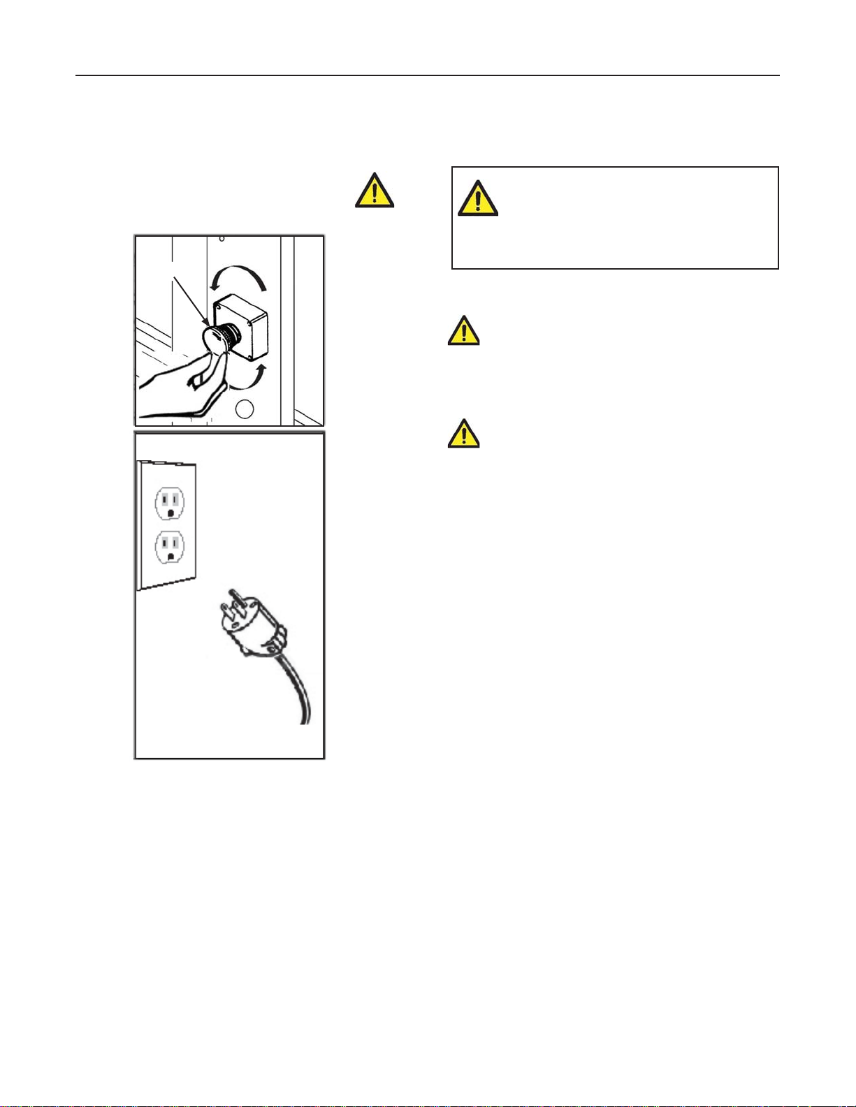
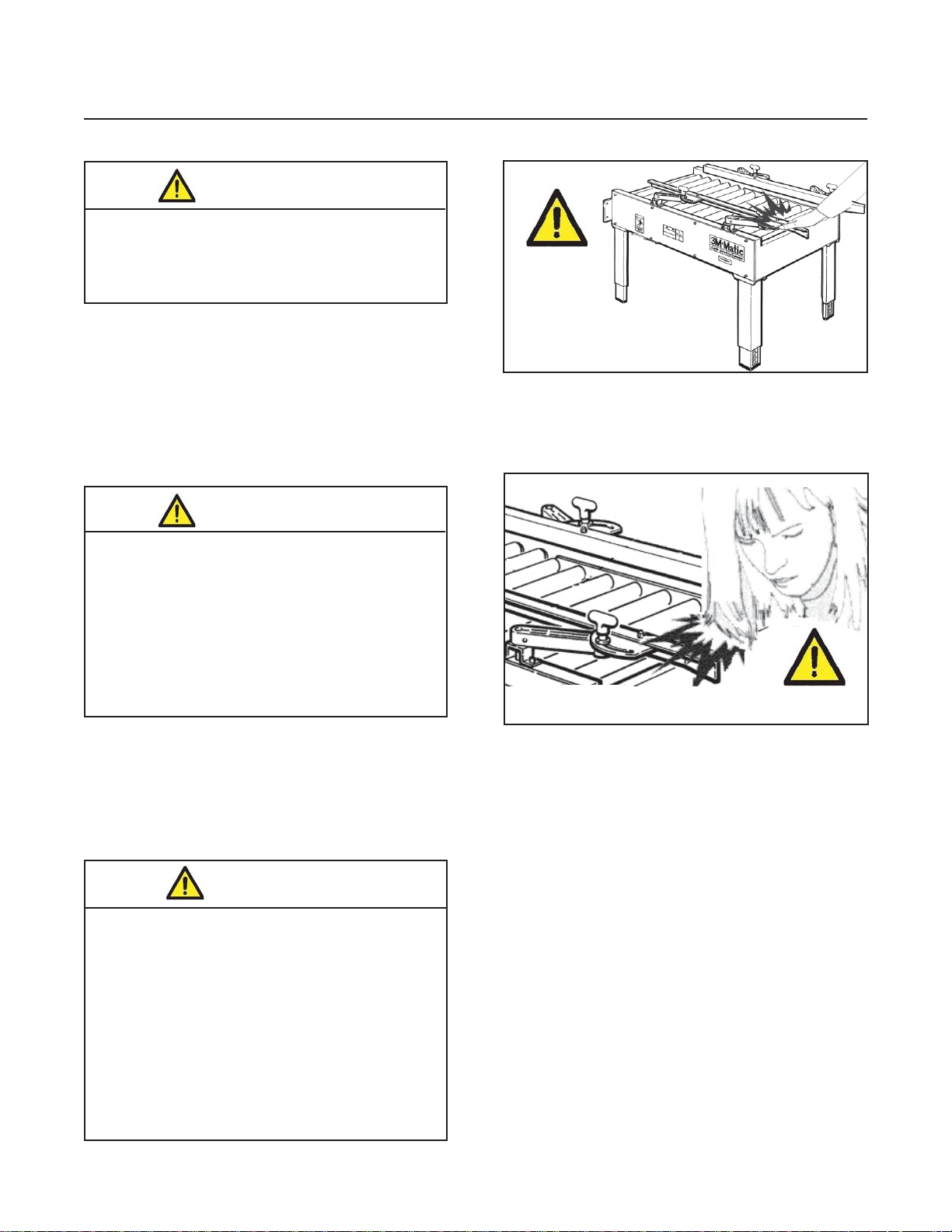
Figure 3-1
The machine is provided with a LATCHING
EMERGENCY STOP BUTTON (Figure 3-1);
when this button is pressed, it stops the machine
at any point in the working cycle. Maintain clear
access to power cord while machine is operating.
Disconnect plug from power source before machine
maintenance (Figure 3-1). Also disconnect air if the
machine has a pneumatic system. Keep this manual
in a handy place near the machine. This manual
contains information that will help you to maintain
the machine in a good and safe working condition.
a80f-if-NA
5
2011 June
Page 14
3-SAFETY (continued)
3.3 Table of Warnings
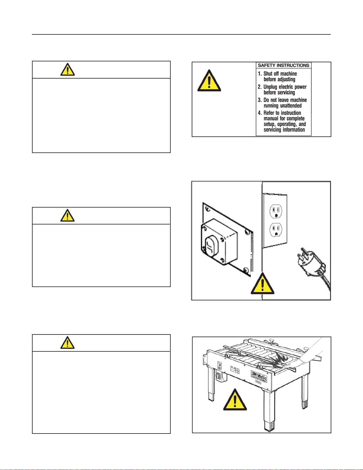
WARNING
• To reduce the risk associated with
mechanical and electrical hazards:
− Read, understand, and follow all safety and
operating instructions before operating or
servicing the Infeed Conveyor/Case Sealer.
− Allow only properly trained and qualifi ed
personnel to operate and service this
equipment.
Figure 3-2
WARNING
• To reduce the risk associated with
pinches, entanglement and hazardous
voltage:
− Turn electrical and air supply off and dis-
connect before performing any adjustments,
maintenance or servicing the machine.
WARNING
• To reduce the risk associated with
pinches and entanglement hazards:
− Do not leave the machine running while
unattended.
− Turn the machine and air supply off when
not in use.
− Never attempt to work on any part of the
machine while the machine is running.
Figure 3-3
Figure 3-4
a80f-if-NA
6
2011 June
Page 15
3-SAFETY (continued)
WARNING
• To reduce the risk associated with fi re
and explosion hazards:
− Do not operate this equipment in potentially
fl ammable/explosive environments.
WARNING
• To reduce the risk associated with
muscle strain:
− Use the appropriate rigging and material
handling equipment when lifting or
repositioning this equipment.
− Use proper body mechanics when
removing or installing taping heads that are
moderately heavy or may be considered
awkward to lift.
Figure 3-5
Figure 3-6
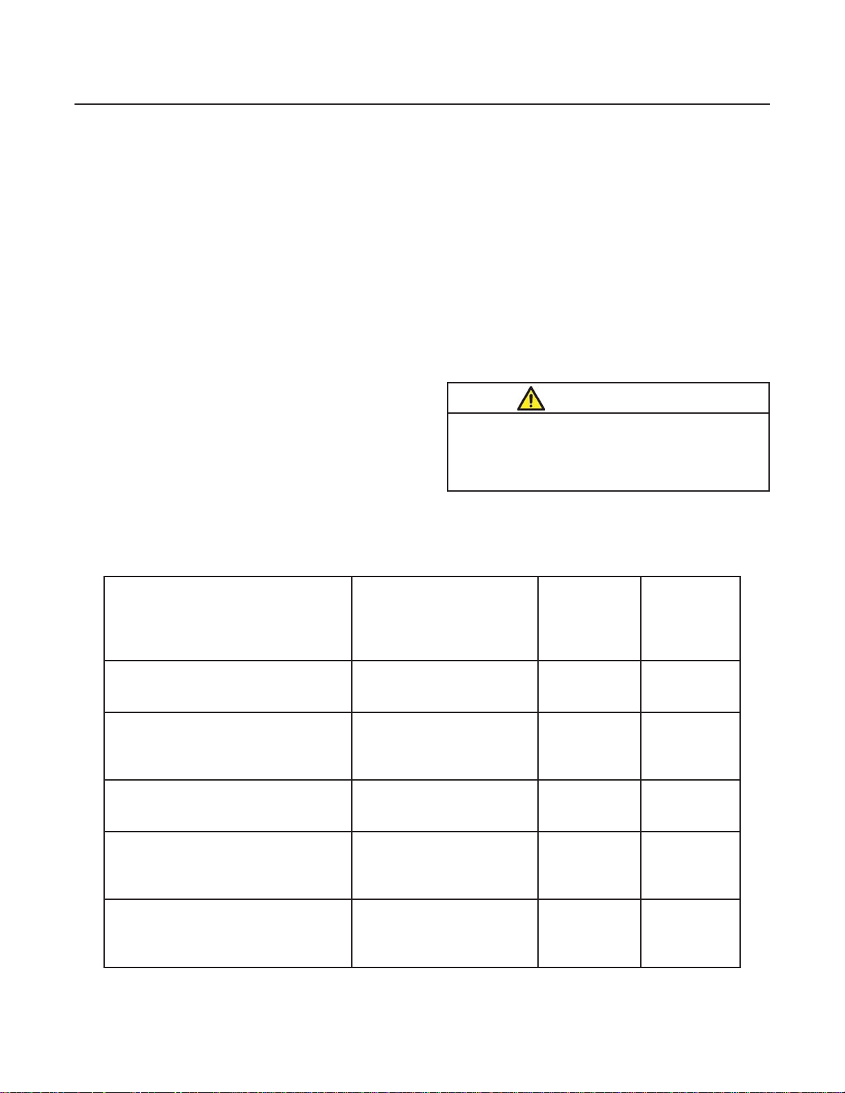
CAUTION
• To reduce the risk associated with
pinch hazards:
− Keep hands clear of the upper head support
assembly as boxes are transported through
the machine.
− Keep hands, hair, loose clothing, and jewelry
away from box compression rollers.
− Always feed boxes into the machine by
pushing only from the end of the box.
− Keep hands, hair, loose clothing, and jewelry
away from moving belts and taping heads.
a80f-if-NA
7
2011 June
Page 16

3-SAFETY (continued)
3.4 Operator's Qualifi cations
- Machine Operator
- Mechanical Maintenance Technician
- Electrical Maintenance Technician
- Manufacturer’s Technician/Specialist
3.5 Number of Operators
The operations described below have been analyzed
by the manufacturer; the recommended number of
operators for each operation provides the best and
safest work performance.
Note: A smaller or greater number of operators
could be unsafe.
3.6 Instructions for a Safe Use of the Machine /
Defi nition of Operator's Qualifi cations
Only persons who have the skills described in the
skill levels section should be allowed to work on the
machine. It is the responsibility of the user to appoint
the operators having the appropriate skill level and
the appropriate training for each category of job.
WARNING
• To reduce the risk associated with
mechanical and electrical hazards:
− Read, understand, and follow all safety and
operating instructions before operating or
servicing the Infeed Conveyor/Case Sealer.
− Allow only properly trained and qualifi ed
personnel to operate and service this
equipment.
3.9 Personal Safety Measures
Safety glasses, safety gloves, safety helmet, safety
shoes, air fi lters, ear muffs - None is required except
when recommended by the user.
3.10 Predictable Actions which are Incorrect and
Not Allowed
- Never try to stop/hold the box while being driven by
the belts. Only use EMERGENCY STOP BUTTON.
- Never work without the safety protections.
3.7 Residual Hazards
The Infeed Conveyor/Case Sealer has been designed and incorporates various safety protections
which should never be removed or disabled. Notwithstanding the safety precautions conceived by
the designers of the machine, it is essential that the
operator and service personnel be warned that the
residual hazards exist which cannot be eliminated.
3.8 Recommendations and Measures to Prevent
Other Hazards which Cannot be Eliminated
- The operator must stay on the working position
shown in the Operation Section (Figure 12-1).
- The operator must belts or put his hands inside
any cavity.
- Never remove or disable the safety devices.
- Only authorized personnel should be allowed
to carry out the adjustments, repairs or main tenance which require operation with reduced
safety protections. During such operations,
access to the machine must be restricted.
When the work is fi nished, the safety protec-
tions must immediately be reactivated.
- The cleaning and maintenance operations must be
performed after disconnecting the electric power.
- Do not modify the machine or any part of it. The
manufacturer will not be responsible for any
modifi cations.
- Clean the machine using only dry cloths or
light detergents. Do not use solvents, petrols, etc.
- Install the machine following the suggested layouts
and drawings. The manufacturer will not be respon sible for damages caused by improper installation.
a80f-if-NA
8
2011 June
Page 17
3-SAFETY (continued)
3.11 Operator's Skill Levels Required to Perform
the Main Operations on the Machine
The Table shows the minimum operator's skill for
each machine operation.
Important: The factory manager must ensure that
the operator has been properly trained on all the
machine functions before starting work.
Skill 1: Machine Operator
This operator is trained to use the machine with the
machine controls, to feed cases into the machine,
make adjustments for different case sizes, to change
the tape and to start, stop and restart production.
Skill 2: Mechanical Maintenance Technician
This operator is trained to use the machine as the
MACHINE OPERATOR and in addition is able to:
• Work with the safety protection disconnected
• Check and adjust mechanical parts
• Carry out machine maintenance operations/repairs
He is not allowed to work on live electrical components
Skill 2a: Electrical Maintenance Technician
This operator is trained to use the machine as the
MACHINE OPERATOR and in addition is able to:
• Work with the safety protection disconnected
• Check and adjust mechanical parts
• Carry out machine maintenance operations /
repairs / adjustments / repair electrical components
He is allowed to work on live electrical panels,
connector blocks, control equipment, etc.
Skill 3: Specialist from the Manufacturer
Skilled operator sent by the manufacturer or its
agent to perform complex repairs or modifi cations
(on agreement with the customer).
WARNING
• To reduce the risk associated with
mechanical and electrical hazards:
− Allow only properly trained and qualifi ed
personnel to operate and service this machine
Operator's Skill Levels Required to Perform the Main Operations on Machine
Required
Operation Machine Status
Machine installation and setup Running with safety
protections disabled
Adjusting box size
Ordinary maintenance Electric power
Extraordinary mechanical
maintenance
Extraordinary electrical
maintenance
Stopped by pressing the
EMERGENCY STOP
button
disconnected
Running with safety
protections disabled
Electric power
disconnected
Operator
Skill
2 and 2a 2
11
21
21
31
Number of
Operators
a80f-if-NA
9
2011 June
Page 18

3-SAFETY (continued)
3.12 Component Locations
Refer to Figure 3-7 below to acquaint yourself with the various components and controls of the Infeed Conveyor.
Box Stop Gate
Conveyor Bed
Mounting Bracket
Adjustable
Side Guides
Electrical Control Box
Figure 3-7—a80f-if Infeed Conveyor Components
a80f-if-NA
10
Box Release
Timer Control
2011 June
Page 19

3-SAFETY (continued)
3.13 Warnings and Replacements Labels
78-8070-1329-3
3M Logo
(not shown)
78-8070-1339-2
Label -
78-8137-1330-8
Service
and
Spares
78-8068-3859-1
Figure 3-8 - Replacement Labels / 3M Part Numbers
a80f-if-NA
11
Leg
Label
78-8060-8481-6
2011 June
Page 20

THIS PAGE IS BLANK
12
Page 21

4-SPECIFICATIONS
4.1 Power Requirements
115V, 60 Hz, 2.8 Amp
5.2 bar gauge pressure [75 PSIG], 28 litre/min @ 21°C, 1.01 bar [1.0 SCFM]
at random cycle rate.
4.2 Operating Rate:
Belt speed is 0.37m/s [72 F.P.M.]
Actual production rate is dependent on operator's dexterity. Boxes must be 18 inches (457mm) apart minimum.
4.3 Operating Conditions
Use in dry, relatively clean environments at 4.4 C to 48.9o C [40o F to 120o F] with clean, dry boxes.
Note: Machine should not be washed or subjected to conditions causing moisture condensation on
components.
IMPORTANT SAFEGUARD
• To reduce the risk associated with fi re and explosion hazards:
− Do not operate this equipment in potentially fl ammable or explosive environments.
4.4 Box Board
125 to 275 P.S.I. bursting test, single wall B, or C fl ute.
4.5 Box Weight and Size Capacities
A. Box weight, fi lled – weight must be suffi cient to actuate center cam located between powered conveyor rollers,
2 kg [4 lbs] minimum, 29 kg [65 lbs] maximum.
B . Box Size: Minimum Maximum
Length 150mm [6.0 inch] 635mm [25 inch]
Width 120mm [4.75 inch] 495mm [19.50 inch]
Height 120mm [4 .75 inch] 510mm [20 inch]
Special modifi cations may be available for carton sizes not listed above.
Contact your 3M Representative for information.
WARNING
a80f-if-NA
13
2011 June
Page 22

4-SPECIFICATIONS (continued)
H2
H1
A
L Max.
L Min.
C
Max.
C
Min.
6. Machine Dimensions
A H1 H2 L C W
Minimum
mm 120 610 108 952.5 118 758
[Inches] [4.72] [24.00] [4.25] [37.50] [4.63] [29.84]
Maximum
mm --- 890 --- 1149.4 562 631
[Inches] --- [35.00] --- [45.25] [22.13] [24.84]
* Casters are optional
W
Min.
W
Max.
Weight – Approximate 95kg [209 pounds] crated
Approximate 82kg [181 pounds] uncrated
14
2011 Junea80f-if-NA
Page 23

5-SHIPMENT-HANDLING-STORAGE, TRANSPORT
3
5.1 Shipment and Handling of Packed Machine
- The machine is fi xed on the pallet with four (4)
bolts and can be lifted by using a fork truck.
- The package is suitable to travel by land and by air.
- Optional sea freight package is available.
Packaging Overall Dimensions
(Figure 5-1)
W
L
L
H
H
W
(See Specifi cations).
5.2 Handling and Transportation of Uncrated
Machine
The uncrated machine should not be moved
except for short distances and indoors ONLY.
Without the supporting pallet, the machine is
exposed to damage and may cause injuries.
To move the machine, use belts or ropes,
paying attention to place them in the points
indicated using care to not interfere with the motor.
5.3 Storage of the Packed or Unpacked Machine
If the machine is not used for a long period,
please take the following precautions:
- Store the machine in a dry and clean place.
- If the machine is unpacked it is necessary to
protect it from dust.
- Do not stack anything over the machine.
- It is possible to stack a maximum of two (2)
machines (if they are in their original packing).
Figure 5-1
Figure 5-2
Figure 5-3Figure 5-
a80f-if-NA
15
2011 June
Page 24

6-UNPACKING
6.1 Uncrating
Cut straps. Cut out staple positions along the bottom
of the shipping box or remove staples with an
appropriate tool (Figure 6-1)
Figure 6-1
After cutting out or removing the staples, lift the
shipping box in order to clear the conveyor
Note: Two (2) persons required.
Removal of Pallet
Using a 10mm combination wrench, remove the fasteners that secure the Infeed Conveyor/Case Sealer
legs to pallet at each leg (as shown in Figure 6-3).
Fasteners
Figure 6-3
6.2 Disposal of Packaging Materials
The a80f-if package is composed of:
Figure 6-2
Transport the conveyor with a fork-lift truck to the
operating position. Lift the pallet at the point
indicated in Figure 6-2 (weight of machine
crated = See Specifi cations).
- Wooden pallet
- Cardboard shipping box
- Wooden supports
- Metal fi xing brackets
- PU foam protection
- PP plastic straps
- Dehydrating salts in bag
- Special bag of laminated polyester/aluminium/
Polyethylene (sea freight package only)
- Polyethylene protective material
For the disposal of the above materials, please follow
the environmental directives or the law in your country.
a80f-if-NA
16
2011 June
Page 25

7-INST ALLATION AND OPERATION
7.1 Operating Conditions
The machine should operate in a dry and relatively
clean environment at 5° to 50°C. with clean dry
boxes-relative humidity between 0% and 80%
7.2 Space Requirements for Machine Operation
and Maintenance Work
Minimum distance from wall (Figure 7-1):
A = 1.0m. (39.4 inches)
B = 0.7m. (27.6 inches)
Minimum height = 2.7m. (106.3 inches)
WARNING
• To reduce the risk associated with
muscle strain:
− Use the appropriate rigging and material
handling equipment when lifting or
repositioning this equipment.
− Use proper body mechanics when
removing or installing taping heads that are
moderately heavy or may be considered
awkward to lift.
B
A
Figure 7-1
WARNING
• To reduce the risk associated with
mechanical and electrical hazards:
− Read, understand, and follow all safety and
operating instructions before operating or
servicing the Infeed Conveyor/Case Sealer.
Bed Height :
he infeed conveyor is equipped with four (4)
adjustable legs that are located at the corners of
the frame. The legs can be adjusted to obtain
different conveyor bed heights from 585mm [23 inch]
minimum to 715mm [28.1 inch] maximum. Refer
to Figure 7-3 and the Specifi cation Section.
1. Block up the conveyor frame to allow
adequate leg adjustment.
2. Loosen, but do not remove, two
M8 x 16mm socket screws in one leg. Adjust
the leg length for the desired bed height.
Retighten the two (2) screws to secure the
leg. Adjust all four (4) legs equally.
M8 x 16
Socket Head
Screws
7.3 Machine Positioning / Bed Height
Figure 7-2
a80f-if-NA
17
Adjustable
Leg
Figure 7-3
2011 June
Page 26

7-INST ALLATION AND OPERATION (continued)
C
Production Line Installation
Refer to Figure 7-4 for installation Setup. Infeed
convey-or bed must be level and equal to case sealer
bed height. Secure infeed conveyor mounting brackets to infeed conveyor and case sealer as shown.
7.4 Preliminary Electric Inspection
Before connecting the machine to the mains please
carry out the following operations:
7.4.1 Make sure that the socket is provided with
an earth protection circuit and that both the
mains voltage and the frequency match
the specifi cations on the name plate.
7.4.2 Check that the connection of the machine
to the mains meets the safety regulations in
your country.
7.4.3 The machine is fi tted with a main switch.
The user will be responsible for testing the
short-circuit current in its facility and should
check that the short-circuit amperage setting
of the machine is compatible with all the
components of the mains system.
Electrical Connection:
The electrical control box, shown in Figure 7-5, contains
the "On/Off" switch with pre-set circuit breaker.
A power supply cord extends from the bottom of the
electrical control box (switch). Plug this cord into the
receptacle on the lower left side (infeed end) of the
a80f-if case sealer frame as shown in Figure 2-4.
7.6 Pneumatic Connection
The infeed conveyor requires a 5.2 bar gauge pressure [75 PSIG], 28 litre/min @ 21°C, 1.01 bar
[1.0 SCFM] compressed air supply.
Remove all packaging materials and tools from the
conveyor before connecting the air line to energize
the pneumatic components.
Plug the air line from the infeed conveyor into the
designated port on the case sealer as shown
(Figure 7-5).
Front and Rear Flaps
must be inside side Flaps
Flat
Head
Screw
Figure 7-4
7.5 Machine Connection to the Mains
For technical specifi cations:
See Section 4 - Specifi cations
- Push the
LATCHING EMERGENCY STOP BUTTON.
- The main switch is normally turned OFF.
Connect the power cord supplied with the machine
to a wall socket using a plug which complies with the
safety regulations of your country.
a80f-if-NA
ELECTRI
Bracket
Socket
Head
Screw
18
Infeed Conveyor must
be level and equal to
Case Sealer Bed
Height
Important! Use care when working with
compressed air.
WARNING
• To reduce the risk associated with
mechanical and electrical hazards:
− Read, understand, and follow all safety
and operating instructions before operating
or servicing the Infeed Conveyor/Case Sealer.
• To reduce the risk associated with
hazardous voltage:
− Position electrical cord away from foot
and vehicle traffi c.
2011 June
Page 27

7-INST ALLATION AND OPERATION (continued)
7.6 Pneumatic Connection (continued)
Important: Use care when working with
compressed air.
WARNING
• To reduce the risk associated with
muscle strain:
− Use the appropriate rigging and material
handling equipment when lifting or
repositioning this equipment.
• To reduce the risk associated with
impact hazards:
− Always unplug electric and turn the valve "Off"
when air supply line is being connected or
disconnected.
7.7 Infeed Conveyor Assembly
1. Remove the conveyor and the package of parts
from the carton.
2. Verify that the package contains two fl at plates,
four (4) M8 x 20 hex socket head screws, and
four (4) M8 fl at washers.
3. To assemble the infeed conveyor, refer to
Figure 7-4 and locate the bolt holes on the infeed
end of the Infeed Conveyor frame.
4. Insert a screw in each hole and attach conveyor to
frame so that only a few threads take hold.
Note: Be sure to line up and level the Machine and
Infeed Conveyor Rollers. Adjustments can be
made to the position of the infeed conveyor
before tightening screws.
a80f-if
Case
Conveyor
a80f-if
Air Line
External
Plug
Infeed
Conveyor
Figure 7-5
5. Ensure that infeed conveyor rollers are level with
machine infeed rollers. Adjust position of
the bed height and infeed conveyor before
tightening all screws. When adjusting Infeed Conveyor
Legs, block up the machine frame to allow
adequate leg adjustment This will help to prevent
damage to the boxes and ensure proper
performance.
6. Remove the Plug and insert/connect the main
air supply line to the "T" connector located at the
midpoint/middle at end of machine (see Figure 7-5).
7. Connect Electric Plug.
WARNING
• To reduce the risk associated with
pinches, entanglement and hazardous
voltage:
− Turn electrical and air supply off and
disconnect before performing any
adjustments, maintenance or servicing the
machine.
Production Line Placement of Infeed Conveyor:
1. Install Infeed Conveyor in production line.
When installing the Infeed Conveyor, be sure to
observe the following guidelines.
a. Infeed Conveyor must be installed level – it is not
designed to convey boxes uphill.
b. Production Line must convey boxes to
Infeed Conveyor at the target speed indicated in
Specifi cations (Section 4) and can be set as shown
in Figure 7-6.
c. Precautions must be taken to prevent excessive
box pressure against the Infeed Conveyor infeed gate.
This will help to prevent damage to the boxes and
ensure proper performance.
d. Infeed and exit conveyors must provide straight
entrance and exit of boxes to/from Infeed Conveyor
and exit conveyor must positively convey boxes away
from machine
Note: The air valve has provisions for lock out/
tag out according to plant regulations.
a80f-if-NA
19
2011 June
Page 28

7-INST ALLATION AND OPERATION (continued)
Box Release Timer:
The Box Release Timer, shown in Figure 7-6, is
located below the conveyor bed at the infeed end of
the conveyor. The timer controls the box stop gate
that releases the boxes to the a80f-if case sealer.
The timer is adjustable for box lengths from 15mm
[6 inch] to 635mm [25 inch]. The timer must be
reset for each change in box length being conveyed
through the a80if case sealer.
For compressed air supply Technical Specifi cations,
Note: A precision regulator is used to balance
the top drive assembly. Due to the self relieving feature of this regulator, a small
amount of air continually vents to the
atmosphere. This is normal and amounts
to approximately 3 litre/min. [0.1 SCFM].
WARNING
• To reduce the risk associated with
entanglement and electric hazards:
− Keep hands and loose clothing away from
moving rollers
− Remove tools and/or other loose objects
before starting conveyor
− Turn off and disconnect electrical and
air supply power before performing any
maintenance or service work on the infeed
conveyor
• To reduce the risk associated with
impact hazards:
− Always turn the valve "Off" when air supply
line is being connected or disconnected.
Pneumatic Components Function
Figure 7-6 – Box Release Timer
Box Release
Timer
Figure 7-7 – Box Setup
Stop
Gate
The air supply operates the adjustable pneumatic
timer and powers movement of two air cylinders that
raise the non-powered box rollers to release one
box for the tape sealing application. The box cam
activates the same two air cylinders that lower the
box rollers and the stop gate retains the next box
from moving forward.
Electrical Components Function
A motor, reducer and drive chain turn the powered
box rollers that convey the box forward for the tape
sealing application.
Operating Sequence
1. The operator places one product fi lled box
(front and rear fl aps folded in) onto the infeed
conveyor non-powered box rollers (in the up
position) and moves it forward to the stop gate
as shown in Figure 7-7.
20
Center Cam
"On" Switch
2011 Junea80f-if-NA
Page 29

7-INST ALLATION AND OPERATION (continued)
2. The operator moves the side guides in against
the box to center it on the conveyor rollers and
tightens the four hand knobs to secure the side
guides. See Figure 7-8. Box must be aligned
with guides to match a80f-if side drive belts.
Additional boxes, ready for the tape sealing
application, are moved in to fl ood the conveyor
behind the lead box.
3. The operator rotates the electrical switch to "On"
to start the powered box rollers.
4. The operator moves the lead box forward onto
the powered box rollers. The box moves over
the center cam that activates the timer causing
the non-powered rollers to pivot down so the
stop gate retains the following box.
5. The lead box moves through the case sealer
taping application. The timer on the infeed
conveyor has been set to raise the non-powered
rollers releasing the next box.
Note – Roller drive motor is designed to run
at a moderate temperature of 40° C [104° F].
In some cases, it may feel warm to the touch.
Figure 7-8 – Side Guide Setup
21
Side Guides
2011 Junea80f-if-NA
Page 30

8-MAINTENANCE AND REPAIRS
8.1 Safety Measures (See section 3)
Carrying out maintenance and repairs may imply
the necessity to work in dangerous situations.
WARNING
• To reduce the risk associated with
mechanical and electrical hazards:
− Read, understand, and follow all safety and
operating instructions before operating or
servicing the Infeed Conveyor.
− Allow only properly trained and qualifi ed
personnel to operate and service this
equipment.
• To reduce the risk associated with
pinches, entanglement and hazardous
voltage:
− Turn electrical and air supply off and
disconnect before performing any
adjustments, maintenance or servicing the
machine or taping heads.
8.2 Tools and Spare Parts Supplied with
the Machine
See Spare Parts Order Section.
8.3 Recommended Frequency of Inspection and Maintenance Operations
Operation Frequency Qualifi cation
Inspection safety features daily 1
Cleaning of machine weekly 1
Lubrication monthly 2
Drive belt replacement when worn 2
8.4 Inspections to be Performed Before and
After Every Maintenance Operation
Before every maintenance operation turn the rotary
switch to OFF on the main power and disconnect the
plug from the control panel. During the maintenance
operation only the operator responsible for this duty
must work on the machine. At the end of every
maintenance operation check the safety devices.
8.5 Check Effi ciency of Safety Features
1. Turn rotary switch STOP/OFF on main power
2. Drive Belt safety guards
(Note: E-Stop located on Main Machine or
Production Line)
a80f-if-NA
22
2011 June
Page 31

8-MAINTENANCE AND REPAIRS (continued)
8.6 Cleaning of Machine
Qualifi cation / Skill 1
Regular slotted containers produce a great deal of
dust and paper chips when processed or handled
in equipment. If this dust is allowed to build up on
machine components, it can cause component
wear. The dust buildup can best be removed
from the machine by a shop vacuum. Depending
on the number and type of boxes used in the
infeed conveyor, this cleaning should be done
approximately once per month. If the boxes are dirty,
or if the environment in which the machine operates
is dusty, cleaning on a more frequent basis may be
necessary. Excessive dirt buildup that cannot be
removed by vacuuming should be wiped off
with a damp cloth.
8.7 Lubrication
Qualifi cation / Skill 2
Figure 8-1
Most of the machine bearings, including the drive
motor, are permanently lubricated and sealed and
do not require additional lubricant. tape. Lubricate
the felt pad on the blade guard without saturating it.
Important: Never attempt to remove dirt from
machine by blowing it off with
compressed air. This can cause dirt
to be blown into critical machine
components and cause premature
wear. Never wash down or subject
machine to conditions causing moisture
condensation as serious equipment
damage could result.
Note: Wipe off excess oil and grease. It will attract
dust which can cause premature equipment wear
and jamming. Take care that oil and grease are
not left on the surface of rollers around which tape
is threaded, as it can contaminate the tape's
adhesive.
8.8 Lubrication Products
Synthetic Silicone Spray may be used on
Guide Pivot Points (Figure 8-1).
a80f-if-NA
23
2011 June
Page 32

8-MAINTENANCE AND REPAIRS (continued)
8.9 List of the Maintenance Operations
Date: Description of Operation
________ ________________________________________________________________
________ ________________________________________________________________
________ ________________________________________________________________
________ ________________________________________________________________
________ ________________________________________________________________
________ ________________________________________________________________
________ ________________________________________________________________
________ ________________________________________________________________
________ ________________________________________________________________
________ ________________________________________________________________
________ ________________________________________________________________
________ ________________________________________________________________
________ ________________________________________________________________
________ ________________________________________________________________
________ ________________________________________________________________
________ ________________________________________________________________
________ ________________________________________________________________
________ ________________________________________________________________
________ ________________________________________________________________
________ ________________________________________________________________
________ ________________________________________________________________
________ ________________________________________________________________
________ ________________________________________________________________
________ ________________________________________________________________
________ ________________________________________________________________
________ ________________________________________________________________
________ ________________________________________________________________
________ ________________________________________________________________
________ ________________________________________________________________
________ ________________________________________________________________
________ ________________________________________________________________
________ ________________________________________________________________
________ ________________________________________________________________
________ ________________________________________________________________
________ ________________________________________________________________
________ ________________________________________________________________
________ ________________________________________________________________
________ ________________________________________________________________
a80f-if-NA
24
2011 June
Page 33

9-ADDITIONAL INSTRUCTIONS
9.1 Information for Disposal of Machine
The machine is composed of the following materials:
- Steel
- Nylon
For machine disposal, follow the regulations
published in each country.
9.2 Emergency Procedures
In case of danger/fi re:
Disconnect plug of power cable from power supply.
(Figure 9-1)
IN CASE OF FIRE
Use a fi re extinguisher that is rated for electrical fi res
(Figure 9-2).
10-ENCLOSURES / SPECIAL INFORMATION
Figure 9-1
10.1 Statement of Conformity
Not Applicable.
10.2 Emission of Hazardous Substances
Nothing to report
Figure 9-2
a80f-if-NA
25
2011 June
Page 34

11-TECHNICAL DIAGRAMS (continued)
11.1 Pneumatic Diagrams
Air Cylinder
Flow
3
Control
2
Air
Cylinder
Air Cylinder
Flow
Control
Flow
Control
1
5
1
3
5
2
4
4
Shuttle
Valve
Shuttle
Valve
Flow
Control
Flow
Control
Timer
3
2
2
13
1
Timer
3
2
2
13
Air
Air Cylinder
Cylinder
Cam Valve
1
Cam
Valve
A80F-IFPneumatic Scheme
TUBO ARIA Ø6
TUBO ARIA Ø4
a80f-if-NA
A80F-IF Novembre 2010 Fig. 15418/B
26
2011 June
Page 35

11-TECHNICAL DIAGRAMS (continued)
11.2 Electric Diagram
a80f-if-NA
27
2011 June
Page 36

11-TECHNICAL DOCUMENTATION AND INFORMATION (continued)
11.3 Spare Parts Order
Replacement Parts Ordering Information and Service
Refer to the fi rst page of this instruction manual "Replacement Parts and Service Information".
Order parts by quoting the following information:
(Refer to the Identifi cation Plate on the Machine)
• MACHINE MODEL
• SERIAL NUMBER
• FIGURE NO.
• POSITION
• 3M PART NO. (11 DIGITS)
• DESCRIPTION
• QUANTITY
Important:
The machine is constantly revised and improved by our designers. The spare parts catalogue is also periodically
updated. It is very important that all the orders of spare parts make reference to the serial number of the machine
(located on the identifi cation plate on the machine).
The manufacturer reserves the right to modify the machine at any time without notice.
Tool Kit
A tool kit, part number 78-8060-8476-6, is available as a stock item. The kit contains the necessary open-end and
hex socket wrenches for use with the metric fasteners on the Infeed Conveyor. The threading tool, part number
78-8076-4726-4, contained in above kit is also available as a replacement stock item.
Label Kit
In the event that any labels are damaged or destroyed, they must be replaced to ensure operator safety.
See Section 3 - Safety.
a80f-if-NA
28
2011 June
Page 37

a80f-if Infeed Conveyor, Type 11000 Frame Assemblies
To Order Parts:
1. Refer to fi rst illustration, Frame Assemblies, for the Figure Number that identifi es a specifi c portion
of the machine.
2. Refer to the appropriate Figure or Figures to determine the parts required and the parts reference number.
3. The Parts List that follows each illustration, includes the Reference Number, Part Number and
Part Description for the parts on that illustration.
Note – The complete description has been included for standard fasteners and some commercially availa-
ble components. This has been done to allow obtaining these standard parts locally, if desired.
4. Order parts by Part Number, Part Description and Quantity required. Also include the model/machine name,
machine type, and serial number that are located on the identifi cation plate.
5. Refer to the fi rst page of this instruction manual “Replacement Parts and Service Information” for
replacement parts ordering information.
Important – Not all the parts listed are normally stocked items. Some parts or assemblies shown are
available only on special order. Contact 3M/Tape Dispenser Parts to confi rm item availability.
Options and Accessories
For additional information on the options and accessories listed below, contact your 3M Representative.
Part Number Option/Accessory
N/A N/A
a80f-if-NA
29
2011 June
Page 38

THIS PAGE IS BLANK
30
Page 39

a80f-if Infeed Conveyor
Fig.15414
Fig.15418 A/B PNEUMA TIC P ARTS
Fig.15417 A/B
Fig.15416
Fig.15417 A/B
Fig.15415 A/B
Figure 15416
Figure 15417
Frame Assemblies
Figure 15415
Figure 15414
Figure 15417
a80f-if-NA
31
2011 June
Page 40

a80f-if Infeed Conveyor
9
9
10
10
2
1
1
2
12 11
11
12
14
14
13
13
15
15
16
2
2
19
19
16
17
17
18
18
16
16
15
15
20
20
3
3
4
4
5
5
5
5
7
7
8
8
6
6
Figure 15414
A80F-IF Ottobre 2010 Fig. 15414
a80f-if-NA
32
2011 June
Page 41

a80f-if
Figure 15414
Ref. No. 3M Part No. Description
15414 - 1 26-1003-7963-0 Screw - Soc. Hd. M8X16
15414 - 2 78-8017-9318-9 Washer - Plain-Metric 8mm
15414 - 3 78-8129-6100-7 Bracket
15414 - 4 78-8137-0635-1 Clamp - Leg
15414 - 5 78-8137-0619-5 Leg
15414 - 6 78-8137-0641-9 Pad - Foot
15414 - 7 78-8137-0640-1 Leg - Inner
15414 - 8 78-8137-4053-3 Label - Leg
15414 - 9 78-8057-5716-4 Screw, Flat Hd. Soc, M8X15
15414 - 10 78-8137-5992-1 Plate
15414 - 11 26-1002-5753-9 Screw-Self Tapping, 7SPX8
15414 - 12 78-8137-5993-9 Safety - Panel
15414 - 13 26-1003-7964-8 Screw Soc. Hd. Hex Soc. Dr., M8X20
15414 - 14 78-8137-5994-7 Box Stop
15414 - 15 26-1003-7948-1 Screw, Soc.Hd Hex Soc. M5X10
15414 - 16 78-8005-5741-1 Washer - Flat, M5
15414 - 17 78-8137-5991-3 Cover
15414 - 18 78-8052-6732-1 Ring, Special M8
15414 - 19 78-8137-5990-5 Shaft
15414 - 20 78-8137-5989-7 Roller with Caps
a80f-if-NA
33
2011 June
Page 42

a80f-if Infeed Conveyor
5
5
A
A
5
5
3
4
4
2 3
2
2
21
112
1
2
2
2
3
4
4
3
A80F-IF Ottobre 2010 Fig. 15415/A
a80f-if-NA
Figure 15415 / 1
34
2011 June
Page 43

a80f-if
Figure 15415 / 1
Ref. No. 3M Part No. Description
15415 - 1 83-0002-7336-3 Screw- Hex Hd M4X14 Zinc. Pl
15415 - 2 78-8005-5740-3 Washer Plain-Metric 4mm Nick.
15415 - 3 78-8059-5584-2 Hub Assy w/Bearing 6001-2RS
15415 - 4 78-8010-7416-8 Nut-Metric, Hex, Steel M4
15415 - 5 78-8059-5585-9 Shaft Gate Assy
a80f-if-NA
35
2011 June
Page 44

a80f-if Infeed Conveyor
A
A
6 6
66
11 10
11 10
89
8
9
B
B
87
5
8
5
B
B
15
15
19
19
18
18
17
17
7
13
1413
12
121313 14
Figure 15415 / 2
a80f-if-NA
17
1621 13 14 202223
1721 2022 14
23
1613
A80F-IF Ottobre 2010 Fig. 15415/B
36
2011 June
Page 45

a80f-if
Figure 15415 / 2
Ref. No. 3M Part No. Description
15415 - 6 78-8137-6032-5 Spacer
15415 - 7 26-1003-7963-0 Screw - Soc. Hd. M8X16
15415 - 8 78-8017-9318-9 Washer - Plain - Metric 8mm
15415 - 9 26-1003-7964-8 Screw Soc. Hd. Hex Soc. Dr., M8X20
15415 - 10 78-8137-6019-2 Roller Assy.
15415 - 11 78-8052-6668-7 Snap - Roller
15415 - 12 78-8023-2234-3 Ring - Snap for 12mm Shaft
15415 - 13 78-8017-9059-9 Washer - Flat for M12 Screw
15415 - 14 78-8059-5587-5 Link
15415 - 15 78-8137-6020-0 Shaft
15415 - 16 78-8016-5855-6 E - Ring 10mm
15415 - 17 26-1004-5510-9 Washer - Plain, M10
15415 - 18 78-8137-6021-8 Shaft
15415 - 19 78-8057-5748-7 Mount, Cylinder Rod End
15415 - 20 78-8059-5588-3 Spacer
15415 - 21 78-8137-6022-6 Shaft
15415 - 22 78-8059-5589-1 Post-Air Cylinder
15415 - 23 26-1000-1613-3 Ring - Retaining 10 DIN 6799
a80f-if-NA
37
2011 June
Page 46

1
3
7
4
5
6
8
13
9
15
16
10
2
2
1
3
4
5
698
12
13
13
10
14
11
7
a80f-if Infeed Conveyor
9
8
698
6
5
5
4
4
3
3
2
2
1
1
14
14
10
10
16
13
13
16
15
15
10
10
9
9
8
14 13
14
13
8
13
13
13
13
12
12
11
11
7
7
6
6
5
5
4
4
7
7
3
3
12
12
11
11
A80F-IF Ottobre 2010 Fig. 15416
a80f-if-NA
Figure 15416
2
2
1
1
38
2011 June
Page 47

a80f-if
Figure 15416
Ref. No. 3M Part No. Description
15416 - 1 78-8059-5582-6 Collar
15416 - 2 78-8055-0789-0 Screw Set M6X6
15416 - 3 78-8059-5580-0 Bracket - Lever
15416 - 4 78-8010-7209-7 Screw, Soc. Hd. M6X12
15416 - 5 78-8059-5559-4 Shaft Lever Assy
15416 - 6 78-8137-6023-4 Indexing Unit Guide Lever
15416 - 7 26-1003-5852-7 Screw - Hex Hd. M10X40
15416 - 8 26-1004-5510-9 Washer - Plain, M10
15416 - 9 78-8017-9074-8 Washer - Nylon 15mm
15416 - 10 78-8070-1549-6 Knob VTR-B-M10
15416 - 11 78-8052-6733-9 Ring, Special M10
15416 - 12 78-8052-6683-6 Stud - Guide
15416 - 13 26-1000-0010-3 Washer - Flat M6
15416 - 14 26-1003-6916-9 Nut Locking Plastic Insert M6
15416 - 15 78-8059-5558-6 Guide - L/H
15416 - 16 78-8059-5556-0 Guide - R/H
a80f-if-NA
39
2011 June
Page 48

a80f-if Infeed Conveyor
A80F-IF Ottobre 2010 Fig. 15417/A
12
4
5
9
6
11
10 15
17
16
14
20
19
18
25
31
2628 27 29
23 24
22
22
21
21
22
22
23 27 30 32
33
3424
13 12
8
9
7
3
24
23
27 38 34
32
33
22
21
22
11
28
17
16
21
22
2627
23 22 24
10
3129
25
18
19
20
1315
1214
9
4
3
5
53
52
51
Figure 15417 / 1
a80f-if-NA
Figure 15417 / 1
8
9
52
7
40
2
1
2011 June
Page 49

a80f-if
Figure 15417
Ref. No. 3M Part No. Description
15417 - 1 78-8076-5366-8 Sprocket - Z=16, 3/8"
15417 - 2 78-8059-5627-9 Shaft Gear Box
15417 - 3 78-8059-5617-0 Set Screw M6X8
15417 - 4 78-8057-5811-3 Key, 6X6X20mm
15417 - 5 78-8059-5620-4 Gear Box
15417 - 6 78-8017-9169-6 Nut - M18X1
15417 - 7 78-8046-8267-8 Motor - 110/110V, 50/60HZ7A1S3
78-8052-6718-0 Motor - 220/415V, 50HZ, 3-Phase
15417 - 8 78-8005-5736-1 Lock Washer for M8 Screw
15417 - 9 2610036904-5 Nut - Hex, M8
15417 - 10 78-8017-9301-5 Screw - Hex Head M8X25
15417 - 11 78-8017-9318-9 Washer - Plain - Metric 8mm
15417 - 12 78-8010-7169-3 Screw - Metric, M6X12, Hex Hd.
15417 - 13 78-8042-2919-9 Washer - Triple, M6
15417 - 14 78-8076-5368-4 Sprocket - Z=15, 3/8"
15417 - 15 78-8076-5367-6 Shaft - Chain Tension
15417 - 16 78-8059-5623-8 Washer
15417 - 17 26-1003-6918-5 Nut, Plastic Insert M10 Hex
15417 - 18 26-1003-7957-2 Screw Soc. Hd. Hex Hd. M6X16
15417 - 19 26-1000-0010-3 Washer - Flat M6
15417 - 20 78-8059-5615-4 Chain Rail
15417 - 21 83-0002-7336-3 Screw - Hex Hd M4X14 Zinc. Pl
15417 - 22 78-8005-5740-3 Washer Plain-Metric 4mm Nick.
15417 - 23 78-8059-5584-2 Hub Assy w/Bearing 6001-2RS
15417 - 24 78-8060-7742-2 Screw, Soc. Hd. Hex. Soc. M6X70
15417 - 25 78-8076-5370-0 Sprocket - Z=17, 3/8"
15417 - 26 78-8076-5323-9 Set Screw - M5X12
15417 - 27 78-8137-6024-2 Roller Assy.
15417 - 28 78-8137-6025-9 Indexing Unit Shaft
15417 - 29 78-8059-5611-3 Key, 4X4X15mm
15417 - 30 78-8059-5610-5 Spacer - Roller
15417 - 31 78-8137-6026-7 Chain
15417 - 32 26-1003-5820-4 Screw - Hex Hd.M5X12
15417 15417 - 34 78-8114-4667-9 Valves Driving Assy
15417 - 35 78-8010-7163-6 Screw - Metric, M5X10, Hex. Hd.
15417 - 36 78-8059-5605-5 Rail - Cam
15417 - 37 78-8055-0746-0 Front Actuator Link 12AF Black
15417 - 38 78-8054-8858-8 Spacer- 8X26, 5mm
15417 - 39 78-8054-8857-0 Shaft - 8X43mm
15417 - 40 78-8076-4774-4 Spring
15417 - 41 26-1002-4955-1 Screw - Self Tap 8PX13
15417 - 42 78-8054-8757-2 Pin - Spring Holder
15417 - 43 26-1005-6859-6 Nut Self Locking M-5
15417 - 44 78-8055-0747-8 Link-Rear Actuator 12AF Black
15417 - 45 26-1003-7947-3 Screw Soc. Hd. Hex Soc. M4X35
33 78-8005-5741-1 Washer - Flat, M5
a80f-if-NA
41
2011 June
Page 50

a80f-if Adjustable Case Sealer
34
35
46
46
38
38
36 35
39
44
4439
353635
35 45
35
45
49
50
50
35
3549
35
35
48 35 39
48
Figure 15417 / 2
47
47
35
4333
43
38
38
39 40 41
37 403341
37
42
42
A80F-IF Ottobre 2010 Fig. 15417/B
a80f-if-NA
42
2011 June
Page 51

a80f-if
Figure 15417
Ref. No. 3M Part No. Description
15417 - 46 78-8059-5606-3 Support - Valve
15417 - 47 78-8054-8758-0 Spacer- Valve Holder
15417 - 48 78-8059-5607-1 Plate - Threaded
15417 - 49 26-1003-7960-6 Screw, Soc. Hd M6X30
15417 - 50 78-8059-5603-0 Cam
15417 - 51 78-8060-7875-0 Plug Male
15417 - 52 78-8076-4532-6 Cord Grip
15417 - 53 78-8137-5956-6 Cable
a80f-if-NA
43
2011 June
Page 52

a80f-if Adjustable Case Sealer
E-Stop
1
1
3
4
3
4
5
5
4
4
3
3
5
5
13
13
15
15
6
6
5
5
2
5
5
12
12
5
5
11
11
10
10 14
27
5
5
12
12
5
5
5
5
8
8 8 9
On-Off
Control Box
89
18
18
7
14
13
13
3
11
11
3
Figure 15418
a80f-if-NA
17
17
44
16
16
19
19
20
20
21
21
22
22
2011 June
Page 53

a80f-if
Figure 15418
Ref. No. 3M Part No. Description
15418 - 1 78-8114-4668-7 Timer - PRT-E-10
15418 - 2 78-8137-6027-5 Air Valve Assy.
15418 - 3 26-1005-5909-0 Elbow
15418 - 4 78-8059-5631-1 Flow Control
15418 - 5 26-1005-6893-5 90 Degree Elbow
15418 - 6 78-8059-5630-3 Air Valve
15418 - 7 78-8137-6028-3 Valve w/Push
15418 - 8 78-8057-5732-1 Fitting - Elbow
15418 - 9 26-1005-6358-9 3 Way - 2 Position Valve
15418 - 10 78-8137-6029-1 Air Distributor Assy.
15418 - 11 78-8059-5633-7 Air Distributor
15418 - 12 26-1005-6910-7 Union - Straight
15418 - 13 78-8060-7853-7 Union - Straight
15418 - 14 78-8137-6030-9 Air Distributor Assy.
15418 - 15 78-8137-6031-7 Air Cylinder Assy.
15418 - 16 78-8059-5590-9 Air Cylinder 32X36
15418 - 17 78-8057-6170-3 Tee - 6mm Tubing
15418 - 18 78-8119-8640-1 Union - Elbow, 31820600
15418 - 19 78-8114-4653-9 Joint - 31560600
15418 - 20 78-8060-7861-0 End Cap
15418 - 21 26-1005-6888-5 Tubing 6/4
15418 - 22 26-1005-6889-3 Tubing
a80f-if-NA
45
2011 June
Page 54

THIS PAGE IS BLANK
46
 Loading...