

3COM SuperStack II PS Hub 40, PS Hub 50, SuperStack II 3C16405, SuperStack II 3C16406, SuperStack II 3C16450 User Manual
Page 1

SuperStack® II PS Hub
®
User Guide
3C16405 — PS Hub 40 12-port
—
3C16406
3C16450
PS Hub 40 24-port
—
PS Hub 50 24-port
http://www.3com.com/
Part No. DUA1640-5AAA02
Published July 1997
Page 2

3Com Corporation
5400 Bayfront Plaza
Santa Clara, California
95052-8145
© 3Com Technologies, 1997.
form or by any means or used to make any derivative work (such as translation, transformation, or
adaptation) without permission from 3Com Technologies.
3Com Technologies reserves the right to revise this documentation and to make changes in content from
time to time without obligation on the part of 3Com Technologies to provide notification of such revision
or change.
3Com Technologies provides this documentation without warranty of any kind, either implied or expressed,
including, but not limited to, the implied warranties of merchantability and fitness for a particular purpose.
3Com may make improvements or changes in the product(s) and/or the program(s) described in this
documentation at any time.
UNITED STATES GOVERNMENT LEGENDS:
If you are a United States government agency, then this documentation and the software described herein
are provided to you su bject to the following restricted rights:
For units of the Department of Defense:
Restricted Rights Legend: Use, duplication or disclosure by the Government is subject to restrictions as set
forth in subparagraph (c) (1) (ii) for restricted Rights in Technical Data and Computer Software clause at 48
C.F.R. 52.227-7013. 3Com Centre, Boundary Way, Maylands Park South, Hemel Hempstead, Herts,
HP2 7YU, UK.
For civilian agencies:
Restricted Rights Legend: Use, reproduction or disclosure is subject to restrictions set forth in subparagraph
(a) through (d) of the Commercial Computer Software - Restricted Rights Clause at 48 C.F.R. 52.227-19 and
the limitations set forth in 3Com Corporation’s standard commercial agreement for the software.
Unpublished rights reserved under the copyright laws of the United States.
If there is any software on removable media described in this documentation, it is furnished under a license
agreement included with the product as a separate document, in the hard copy documentation, or on the
removable media in a directory file named LICENSE.TXT. If you are unable to locate a copy, please contact
3Com and a copy will be provided to you.
Unless otherwise indicated, 3Com registered trademarks are registered in the United States and may or may
not be registered in other countries.
3Com, LANplex, LinkBuilder, NETBuilder II, SmartAgent, SuperStack and Transcend are registered trademarks
of 3Com Corporation. CoreBuilder and FMS are trademarks of 3Com Corporation. 3ComFacts is a service
mark of 3Com Corporation.
CompuServe is a registered trademark of CompuServe, Inc. Windows and Windows NT are registered
trademarks of Microsoft. IPX is a registered trademark of Ideographix, Inc. Netscape Navigator is a
trademark of Netscape Communications Corporation.
Other brand and product names may be registered trademarks or trademarks of their respective holders.
All rights reserved. No part of this documentation may be reproduced in any
Environmental Statement
It is 3Com’s policy to be environmentally friendly in all its operations. This manual is printed on paper that
comes from sustainable, managed European forests. The production process for making the pulp has a
reduced AOX level (adsorbable organic halogen) resulting in elemental chlorine free paper.
The paper is fully bio-degradable and recyclable.
ii
Page 3

C
ONTENTS
MPORTANT SAFETY INFORMATION
I
INFORMATION DE SÉCURITÉ IMPORTANTE
L’
ICHTIGE SICHERHEITSHINWEISE
W
BOUT THIS GUIDE
A
Introduction 1
How to Use This Guide 2
Conventions 2
1
2
BOUT THE
A
Introduction 1-1
Features 1-2
How You Can Use the PS Hub 1-4
Building Up a Network 1-4
Expanding an Existing Network 1-5
Migrating to Higher Performance 1-6
Workgroups 1-7
What Are Workgroups? 1-7
Segments and Port Switching 1-8
Workgroup Example 1-11
HOW
Overview 2-1
PS Hub 40 2-2
PS Hub 50 2-2
Segment Switch 2-2
PS Hub 50 Transceiver Module Slot 2-6
THE
PS H
PS H
UB
UBS DIFFER
Page 4

3
4
SING THE
U
LEDs and Ports 3-1
Before You Start 3-4
What Other Equipment Is Needed? 3-4
Positioning the PS Hub 3-6
Using the Rubber Feet 3-6
Using the Labels 3-7
Rack and Wall Mounting 3-8
Rack Mounting 3-8
Wall Mounting 3-9
Connecting Workstations to Your Hub 3-11
Using Transceiver Modules 3-12
Connecting PS Hubs Together (Stacking) 3-12
About Cascade Cables 3-13
Using Cascade Cables 3-14
Using Hot Swap Cascade Units 3-15
Connecting Different Hubs and Stacks to Your Hub 3-16
Powering On the Units 3-17
Spot Checks 3-17
OAD BALANCING
L
Overview 4-1
How Does Load Balancing Work? 4-2
Using an External Switch 4-3
Performing Load Balancing 4-3
PS H
UB
5
iv
ANAGING THE
M
Introduction 5-1
Why Manage Your Stack? 5-2
How You Can Manage Your Stack 5-3
Command Line Interface 5-3
Web Interface 5-3
SNMP Network Management 5-4
Methods of Management 5-5
Requirements for Managing Over the Network 5-6
IP Addresses 5-7
PS H
UB
Page 5

Command Line Interface (CLI) 5-8
Through the Console Port 5-8
Over the Network 5-11
Web Interface 5-12
Through the Console Port 5-12
Over the Network 5-12
Which Web Browsers are Supported? 5-12
Quick Config Manager 5-13
Through the Console Port 5-13
Over the Network 5-14
6
7
SING THE COMMANDLINEINTERFACE
U
Accessing the CLI 6-2
Initial Access 6-2
Logging On 6-2
Logging Off 6-3
Using the CLI Menus 6-4
CLI Menu Structure 6-4
Navigating the Menus and Entering Commands 6-5
Quick Guide to the Commands 6-6
Commands 6-7
Changing the Password 6-7
Setting the IP Configuration 6-8
Viewing the Configuration 6-9
Resetting the Stack 6-10
Initializing the Stack 6-11
Configuring Another Unit in the Stack 6-11
Enabling and Disabling RMON Filter Capture 6-12
ANAGEMENT USING THE WEBINTERFACE
M
Accessing the Web Interface 7-1
About the Web Interface 7-4
General Components 7-4
Page Components 7-6
Web Interface Map 7-6
v
Page 6

Using the Web Interface 7-7
Unit View and Unit Pages 7-8
User Access Levels 7-9
Exiting the Web Interface 7-9
Online Help System and Documentation 7-9
Unit Pages 7-10
Unit View 7-10
Unit Status 7-11
Management Address 7-12
Port Setup 7-13
Console Port Configuration 7-14
Segment Configuration 7-15
Switch Configuration 7-16
Permanent Address Management 7-16
Management Settings Pages 7-17
Documentation 7-17
Getting Started 7-18
Password Setting 7-19
System Name 7-19
Configuration Pages 7-20
Initialize 7-20
Load Balancing 7-20
Reset 7-20
Resilient Links 7-21
Add Resilient Link 7-23
Software Upgrade 7-24
Health Pages 7-25
Segment Graph 7-25
8
ROBLEM SOLVING
P
Isolating a Problem 8-1
Solving Problems With the Hub 8-2
Solving Problems With the Command Line Interface 8-3
Solving Problems With the Web Interface 8-4
Solving Problems With an SNMP Network Management Application 8-5
vi
Page 7

A
IMENSIONS
D
Dimensions and Operating Environment A-1
BABT Approval (for U.K. Users Only) A-1
Standards A-2
Cabling A-3
10BASE-T Cable A-3
Console Cable A-4
Modem Cable A-5
Cascade Connections A-6
Management Settings A-6
TANDARDS AND CABLING
, S
B
ANAGEMENT USING QUICKCONFIGMANAGER
M
Installing Quick Config Manager and the Load Balancing Tool B-2
Installation Requirements B-2
Installation Procedure B-3
Running Quick Config Manager B-4
Configuring Multiple Stacks B-4
Selecting Your Management Access Method (Windows ‘95 and
Windows NT only) B-5
Quick Config Manager Window Map B-5
Accessing the Stack B-8
Giving the Stack an IP Address B-9
Viewing the Stack B-12
Configuring Segments B-14
Configuring the Segment Switch B-17
Load Balancing B-18
Menus B-19
Changing the Community Name B-19
Viewing Current Utilization B-20
Viewing Utilization History B-21
Fixing and Unfixing Segments and Ports B-23
Performing Load Balancing B-25
Changing the Console Port Settings B-27
Upgrading a Stack B-28
Solving Problems With Quick Config Manager B-29
vii
Page 8

C
ERIAL WEB UTILITY
S
Introduction C-1
Installing the Serial Web Utility C-1
Using the Serial Web Utility C-3
Solving Problems With the Serial Web Utility C-4
D
E
GENT UPGRADE UTILITY
A
Using the Upgrade Utility D-1
Solving Problems With the Agent Upgrade Utility D-3
ECHNICAL SUPPORT
T
Online Technical Services E-1
World Wide Web Site E-1
3Com Bulletin Board Service E-1
3ComFacts Automated Fax Service E-2
3ComForum on CompuServe Online Service E-3
Support from Your Network Supplier E-3
Support from 3Com E-4
Returning Products for Repair E-5
LOSSARY
G
NDEX
I
3COM C
EMC S
viii
ORPORATION LIMITED WARRANTY
TATEMENTS
Page 9

I
MPORTANT
I
NFORMATION
WARNING: Warnings contain directions that you must follow for your
personal safety. Follow all instructions carefully.
Please read the following safety information thoroughly before
installing the PS Hub.
■ Installation and removal of the unit must be carried out by qualified
personnel only.
■ Connect the unit to an earthed power supply to ensure compliance
with European safety standards.
■ The power cord set must be approved for the country where it will
be used.
■ The appliance coupler, that is, the connector to the device itself and
not the wall plug, must have a configuration for mating with an
EN60320/IEC320 appliance inlet.
S
AFETY
■ For U.S.A. and Canada:
The cord set must be UL-approved and CSA certified.
■
The minimum specification for the flexible cord is:
■
No. 18 AWG
Type SV or SJ
3-conductor
The cord set must have a rated current capacity of at least 10A.
■
The attachment plug must be an earth-grounding type with a
■
NEMA 5-15P (15A, 125V) or NEMA 6-15P (15A, 250V)
configuration.
■ For Denmark:
The supply plug must comply with section 107-2-D1, standard
■
sheet DK2-1a or DK2-5a.
Page 10

■ For Switzerland:
The supply plug must comply with SEV/ASE 1011.
■
■ It is essential that the mains socket outlet is installed near to the
unit and is accessible. You can only disconnect the unit by
removing the appliance coupler from the unit.
■ This unit operates under SELV conditions (Safety Extra Low Voltage)
according to IEC 950, the conditions of which are maintained only if
the equipment to which it is connected is also operational under
SELV.
■ France and Peru only:
This unit cannot be powered from IT (impedance à la terre)
■
supplies. If your supplies are of the IT type, this unit should be
powered by 230V (2P+T) via an isolation transformer ratio 1:1,
with the secondary connection point labelled Neutral, connected
directly to Earth (Ground).
■ U.K. only:
The PS Hub is covered by Oftel General Approval,
■
NS/G/12345/J/100003, for indirect connection to a public
telecommunications system. This can only be achieved using the
console port on the unit and an approved modem.
■ Twisted Pair RJ45 ports: These are shielded RJ45 data sockets. They
cannot be used as telephone sockets. Only connect RJ45 data
connectors to these sockets. Either shielded or unshielded data
cables with shielded or unshielded jacks can be connected to these
data sockets.
■ Sockets for Redundant Power System (RPS): Only connect a 3Com
Redundant Power System to this socket. For details, follow the
installation instructions in the manuals accompanying the Redundant
Power System.
Page 11

L’
INFORMATION D
I
MPORTANTE
AVERTISSEMENT: Les avertissements contiennent les directions que
vous devez suivre pour votre sécurité personnelle. Suivez toutes les
directives avec soin.
Veuillez lire à fond l'information de la sécurité suivante avant d'installer
le PS Hub.
■ L'installation et l'enlèvement de l'unité doivent être faits seulement
par le personnel qualifié.
■ Brancher l'unité à une source de courant mise à la terre pour assurer
la conformité aux normes de sécurité européennes.
■ La cordon d'alimentation surmoulé doit être approuvé pour le pays
auquel il sera utilisé.
■ Le socle de connecteur, c'est-à-dire, le connecteur à l'appareil
lui-même et non pas la prise murale, doit avoir une configuration
pour le branchement avec une admission d'appareil
EN60320/IEC320.
E
S
ÉCURITÉ
■ Pour U.S.A. et le Canada:
Le cordon surmoulé doit être UL Certifié et CSA Certifié.
■
Les spécifications minimales pour le cordon souple sont:
■
No. 18 AWG
■
Type SV ou SJ
3-conducteur
Le cordon surmoulé doit avoir une capacité de courant calculée
■
au moins de 10A.
La fiche de fixation doit être un type mis à la terre avec une
■
configuration NEMA 5-15P (15A, 125V) ou NEMA 6-15P (15A,
250V).
Page 12

■ C'est essentiel que le socle soit installé près de l'unité et soit
accessible. Vous pouvez seulement débrancher l'unité en enlevant
la fiche d'alimentation de la prise de courant.
■ Cette unité marche sous les conditions SELV (Safety Extra Low
Voltage) conformément à IEC950, ces conditions sont maintenues
seulement si le matériel auquel elle est branchée, est aussi en
exploitation sous SELV.
■ Seulement Pour La France et Le Pérou:
Cette unité ne peut pas être mise en marche des sources de
■
courant IT (Impédance à la terre). Si vos sources de courant sont
de type IT, cette unité doit être alimentée par 230V (2P+T) via un
rapport de transformation d'isolation de 1:1, avec un point de
connexion secondaire étiqueté Neutre, branché directement à la
Terre (à la Masse).
■ Les ports RJ45 de paire tordue: Ceux-ci sont les prises de courant de
données RJ45 protégées. Ils ne peuvent pas être utilisés comme
prises de courant téléphoniques. Brancher seulement les connecteurs
RJ45 de données à ces prises de courant. Les câbles de données
blindés ou non blindés, avec les jacks blindés ou non blindés, l'un
ou l'autre, peuvent être branchés à ces prises de courant de
données.
■ Socle Pour Alimentation Multiple: Brancher seulement une
alimentation multiple de 3Com à cet socle. Suivre pour les détails les
directives de l’installation dans le manual qui accompagne
l’alimentation multiple.
Page 13

W
ICHTIGE
WARNUNG: Warnungen enthalten Anweisungen, die zur eigenen
Sicherheit unbedingt zu beachten sind. Bitte befolgen Sie alle
Anweisungen sorgfältig und genau.
Bitte unbedingt vor dem Einbauen des PS Hub Einheit die folgenden
Sicherheitsanweisungen durchlesen.
S
ICHERHEITSHINWEISE
■ Ein- und Ausbau des Gerätes ist
■ Das Gerät an geerdete Stromversorgung anschließen, um eine
Übereinstimmung mit den europäischen Sicherheitsbestimmungen
zu gewährleisten.
■ Der Anschlußkabelsatz muß mit den Bestimmungen des Landes
übereinstimmen, in dem er verwendet werden soll.
■ Die Anordnung der Gerätsteckvorrichtung, d.h. die Steckverbindung
am Gerät selbst im Gegensatz zum Wandstecker, muß in den
EN60320/IEC320 Zuführungsstecker am Gerät passen.
■ Es ist wichtig, daß der Netzstecker sich in unmittelbarer Nähe zum
Gerät befindet und leicht erreichbar ist. Das Gerät kann nur durch
Herausziehen des Verbindungssteckers aus der Steckdose vom
Stromnetz getrennt werden.
■ Das Gerät wird mit Sicherheits-Kleinspannung nach IEC 950 (SELV =
Safety Extra Low Voltage) betrieben. Angeschloßen werden können
nur Geräte, die ebenfalls nach SELV betrieben werden.
■ Gedrehte paarfache RJ45 Anschlüsse: Hierbei handelt es sich um
abgeschirmte RJ45 Datenbuchsen, die nicht als Telefonbuchsen
verwendbar sind. Nur RJ45 Datensteckverbinder an diese Buchsen
anschließen. Diese Datenstecker können entweder mit
abgeschirmten oder unabgeschirmten Datenkabeln mit
abgeschirmten oder unabgeschirmten Klinkensteckern verbunden
werden.
nur von Fachpersonal vorzunehmen.
Page 14

■ Steckdose Für Redundant Power System: Nur ein 3Com Redundant
Power System an diese Steckdose anschließen. Für weitere Angaben
die genauen Einbauanweisungen im Handbuch zum Redundant
Power System befolgen.
Die Einheit ist unter keinen Umständen an einen Wechselstrom
Netzstecker (A.C.) anzuschließen, wenn dieser keine Erdung hat.
Page 15

A
BOUT
T
HIS
G
UIDE
Introduction
Audience
Description
This guide describes how to set up and manage these SuperStack®II
PS Hubs:
■ 3C16405 — PS Hub 40 12-port
■ 3C16406 — PS Hub 40 24-port
■ 3C16450 — PS Hub 50 24-port
This guide is intended for users who have networking experience. If you
have used 3Com’s SuperStack II range of products, you may already be
familiar with using this kind of hub. We recommend that you read
through this guide as the PS Hub has a number of important features
which are described in this guide.
If you are familiar with the PS Hub and know how the PS Hub’s port
switching and segments work, you may only want to know how the
PS Hub 40 and PS Hub 50 are different; refer to Chapter 2
When referring to both the PS Hub 40 and PS Hub 50 generally, this
guide uses the term ‘
For information on the Limited Warranty, refer to the “3Com
Corporation Limited Warranty” at the back of this guide
A Quick Reference Guide accompanies this user guide, and provides a
summary of some of the information in this user guide.
PS Hub
’.
.
.
If there are Release Notes shipped with your product and the
information in them differs from the information in this guide, follow
the Release Notes.
Page 16
2 A
BOUT THIS GUIDE
How to Use
This Guide
This table shows where to find specific information in this guide.
If you are looking for... Turn to...
An introduction to the hub, workgrouping and segments Chapter 1
Information on how the PS Hub 40 and PS Hub 50 are different
from each other
Information on installing and using the hub Chapter 3
An introduction to load balancing and how it works Chapter 4
Ways you can manage the hub and how to start your
management session
Information on using the Command Line Interface to set up
the hub for management
Information on using the web interface to manage the hub or
stack of hubs
Information on
The hub’s dimensions, the standards it conforms to, and the
cabling you can use with it
Information on using Quick Config Manager to manage the hub
or stack of hubs
Information on installing and using the serial web utility Appendix C
Information on using the agent upgrade utility Appendix D
Technical support Appendix E
solving any problems
Chapter 2
Chapter 5
Chapter 6
Chapter 7
Chapter 8
Appendix A
Appendix B
Conventions
Tab le 1 and Table 2 list conventions that are used throughout this
guide.
Table 1
Icon Notice Type Alerts you to...
Notice Icons
Information note Important features or instructions
Caution Risk of system damage, loss of data, or to personal
safety.
Warning Risk of severe personal injury
Page 17

Conventions 3
Table 2
Text Conventions
Convention Description
Syntax
The word ‘syntax’ means you must evaluate the syntax
provided and supply the appropriate values. Placeholders
for values you must supply appear in angle brackets.
Example:
Change the password by using the following syntax:
password <string>
In this example, you must supply a password string for
<string>.
Comman ds
The word ‘command’ means you must enter the
command exactly as shown in text and press the Return or
Enter key. Example:
To exit, enter the following command:
Logout
This guide always gives the full form of a command in
uppercase and lowercase letters. However, you can
abbreviate commands by entering only the uppercase
letters and the appropriate value. Commands are not
case-sensitive.
Screen displa ys
This typeface represents information as it appears on the
screen.
The words ‘enter’
and ‘type’
When you see the word ‘enter’ in this guide, you must
type something, and then press the Return or Enter key.
Do not press the Return or Enter key when an instruction
simply says ‘type’.
[Key] names Key names appear in text in one of two ways:
■
Referred to by their labels, such as “the Return key” or
“the Escape key”
■
Written with brackets, such as [Return] or [Esc].
If you must press two or more keys simultaneously, the key
names are linked with a plus sign (+). Example:
Press [Ctrl]+[Alt]+[Del].
Menu commands
buttons
and
Words in
italicized
type
Words in
bold
type Bold text denotes key features.
Menu commands or button names appear in italics.
Example:
From the
Italics emphasize a point or denote new terms at the place
Configure
menu, select
Community/Polling...
where they are defined in the text.
Page 18

4 A
BOUT THIS GUIDE
Page 19
1
A
BOUT THE
This chapter contains the following topics:
■ Features and benefits of the PS Hub
■ How the PS Hub can be used
■ Using workgroups
■ Description and example of the PS Hub segmentation
■ How the PS Hub works
PS H
UB
Introduction
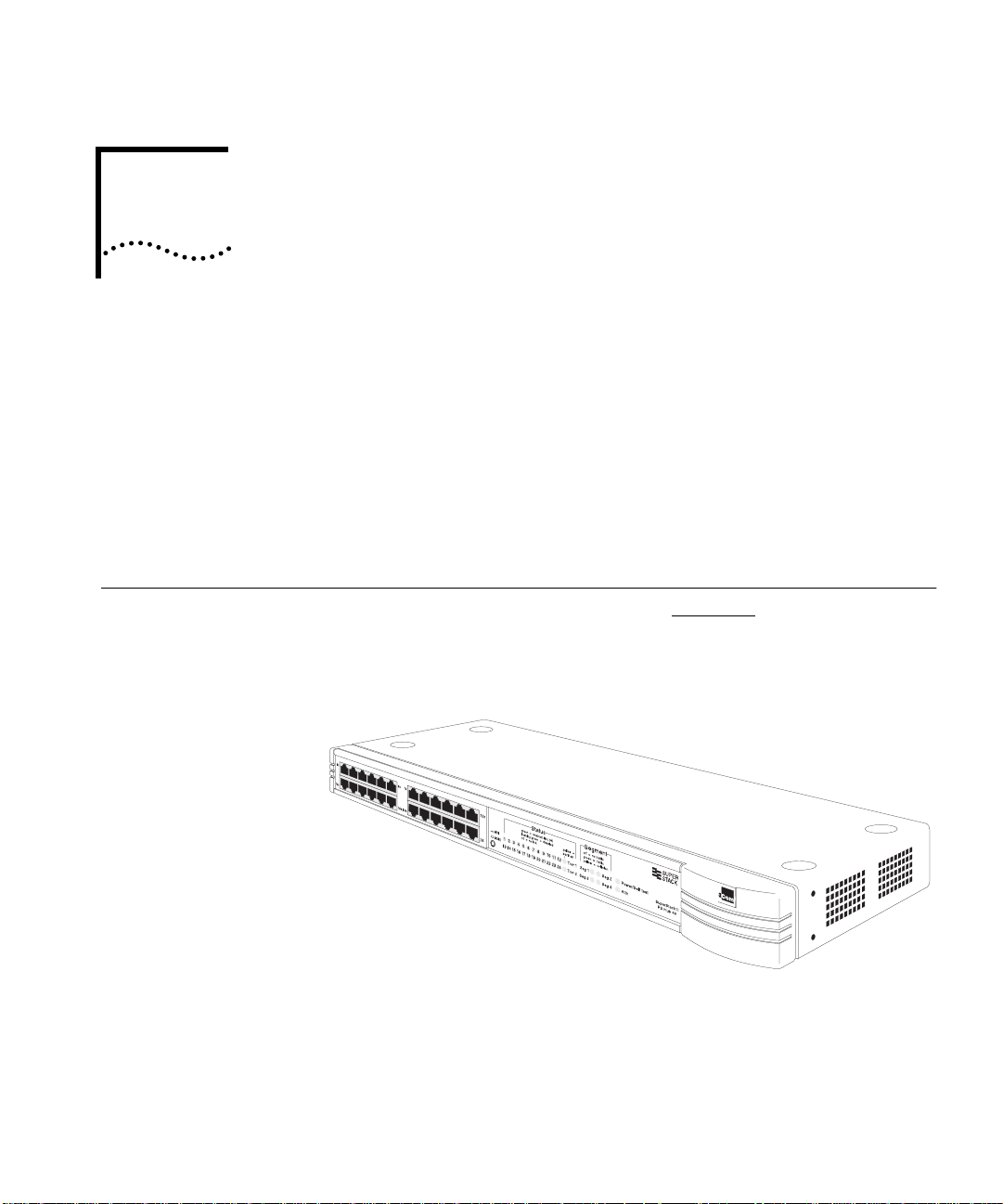
The SuperStack® II PS Hub, as shown in Figure 1-1, is a flexible
managed Ethernet repeater which is very easy to set up and manage.
It can be used to build a small network or to expand a larger, more
established network.
Figure 1-1
The PS Hub is part of 3Com’s SuperStack II PS Hub range, which
incorporates many of the features from the successful SuperStack II
range. SuperStack II products can be combined to create a network
that can change and grow with your networking needs.
The PS Hub
Page 20

1-2
C
HAPTER
1: A
BOUT THE
PS H
UB
Features
The PS Hub 40 and PS Hub 50 share many features:
NOTE: These terms and features are described in this chapter and the
following chapters.
12 or 24 shielded twisted pair ports for easy connection to
■
10BASE-T networks. An MDI/MDIX switch allows you to cross-over
one of these ports, for connection to other types of hubs and
network equipment.
One or two transceiver module slots, providing a choice of media
■
options:
The PS Hub 40 has two 10Mbps transceiver module slots that
■
can be fitted with 3Com 10Mbps transceiver modules.
The PS Hub 50 has one transceiver module slot that can be fitted
■
with a 3Com 10Mbps or 100Mbps transceiver module.
SuperStack II architecture — You can stack up to 10 hubs
■
(six if free standing), giving you a possible 260 ports per stack.
LEDs for quick viewing of hub and port status.
■
Hot-swappable technology which allows hubs to be added and
■
removed from a stack without affecting stack performance.
Mounting brackets for easy installation into a standard 19 inch rack,
■
or onto a table or wall.
+5 Lifetime Limited Warranty — Please refer to the “3Com
■
Corporation Limited Warranty” at the back of this guide for more
information.
DUA1640-5AAA02
Page 21

Introduction 1-3
Management
Features
Complete SmartAgent™ management which is built into each hub;
■
no additional management cards are needed. When PS Hubs are
stacked, the management is distributed between all hubs in the
stack.
Easy to use built-in management interfaces for configuration of your
■
hub or stack locally or over the network:
A Command Line Interface for quick configuration of IP
■
information for the hub.
A web interface for comprehensive management of the hub
■
using any suitable web browser.
Additional management software (supplied on the CD-ROM),
■
including 3Com’s Transcend
Windows
An implementation of SNMP for management over the network,
■
®
.
®
Quick Configuration Manager for
using the IP protocol.
Support for traps (messages) which can alert an SNMP network
■
management station of any problems.
Built-in security and resilience, which protects your network.
■
Port switching — Allows you to build up workgroups by switching
■
ports easily between the four internal segments. When stacked, all
four segments are carried between the hubs by cascade cables.
DUA1640-5AAA02
Automated load balancing — Configures the segments so that the
■
traffic is distributed evenly across them, making the segments more
efficient. It also analyses inter-segment traffic and moves frequently
communicating ports to the same segment.
Page 22
1-4
C
HAPTER
1: A
BOUT THE
PS H
UB
How You Can
Use the PS Hub
Building Up a
Network
The flexibility of the PS Hub allows it to be used in a number of ways.
You can build up a network or expand a large, established network.
For information on connecting and using your equipment, refer to
Chapter 3
.
The PS Hub can be used on its own or in a stack with other PS Hubs.
All PS Hubs have a useful feature called
port switching
which allows
you to create workgroups within your stack. For information on this
feature, refer to “Segments and Port Switching” on page 1-8
.
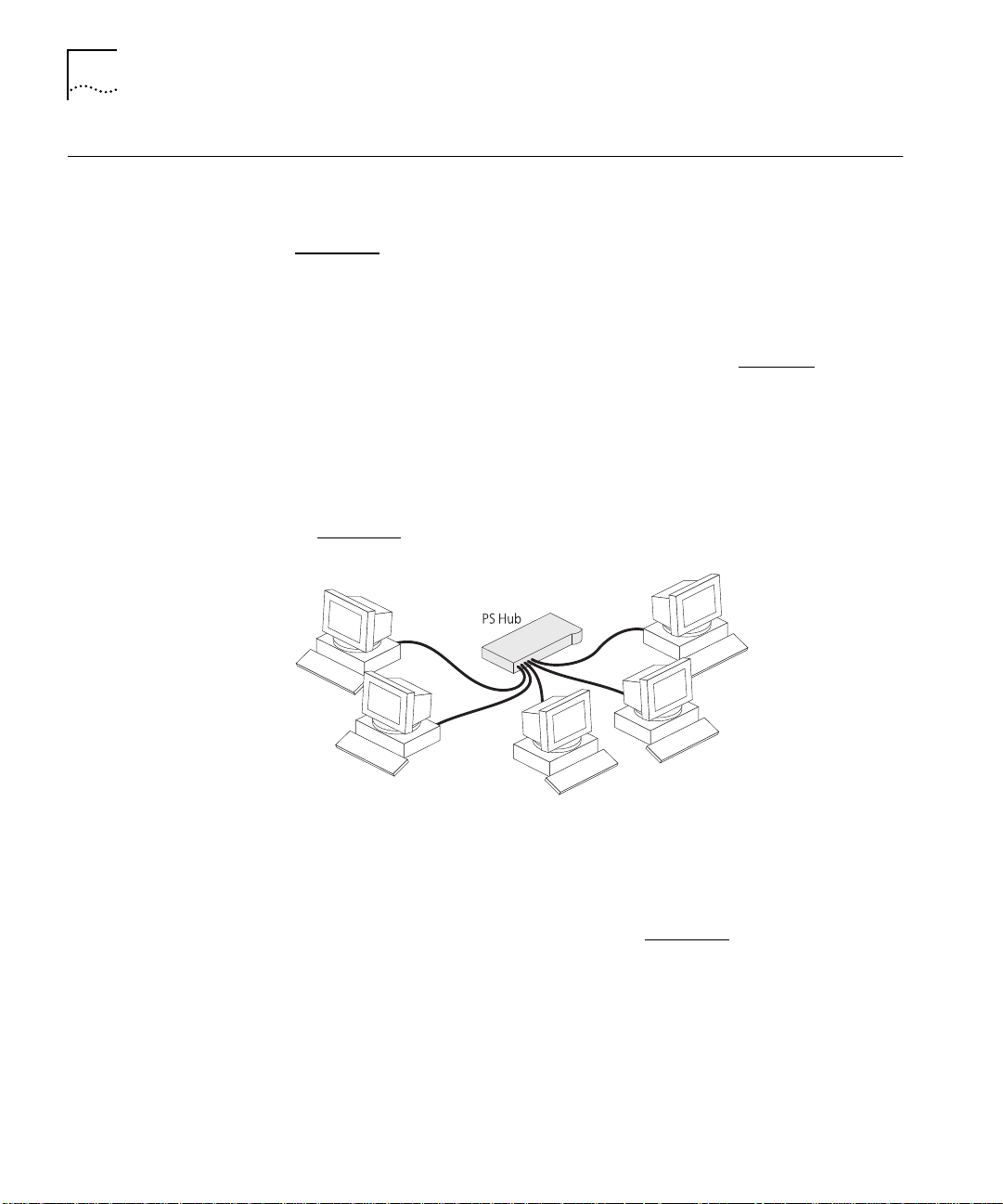
The PS Hub is ideal for building up a new network. It has its own
built-in management and comes ready to use. The PS Hub range is
totally scalable, enabling you to start with one hub and add to it as
your network grows. You can connect your workstations and other
network equipment to the PS Hub to build a small network, as shown
in Figure 1-2
.
Figure 1-2
Building Up a Network
When your network grows, you can expand it easily by adding more
PS Hubs. The PS Hub also has an MDI/MDIX switch which enables your
network to expand further by connecting to other types of hubs, stacks
and networking equipment, as shown in Figure 1-3
.
DUA1640-5AAA02
Page 23
How You Can Use the PS Hub 1-5
Expanding an
Existing Network
Figure 1-3
Connecting to Other Stacks and Hubs
You can add PS Hubs to your existing network to expand the number
of user connections. Each PS Hub has its own built-in management
which is distributed throughout the PS Hubs in the stack. This provides
fault tolerance because there is no single point of failure; all hubs have
management capability (should they become isolated).
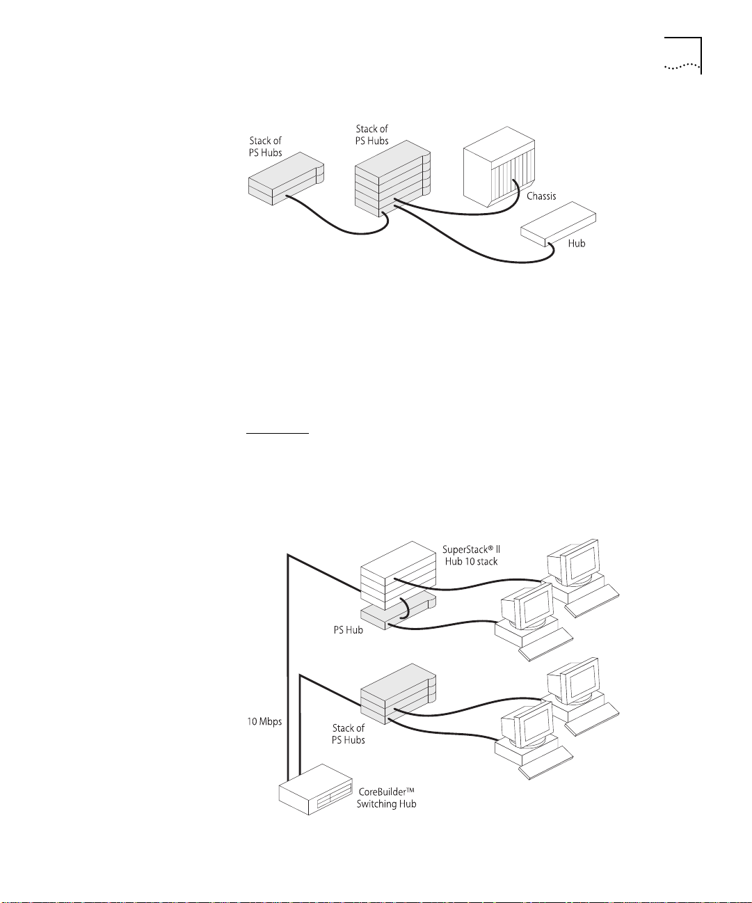
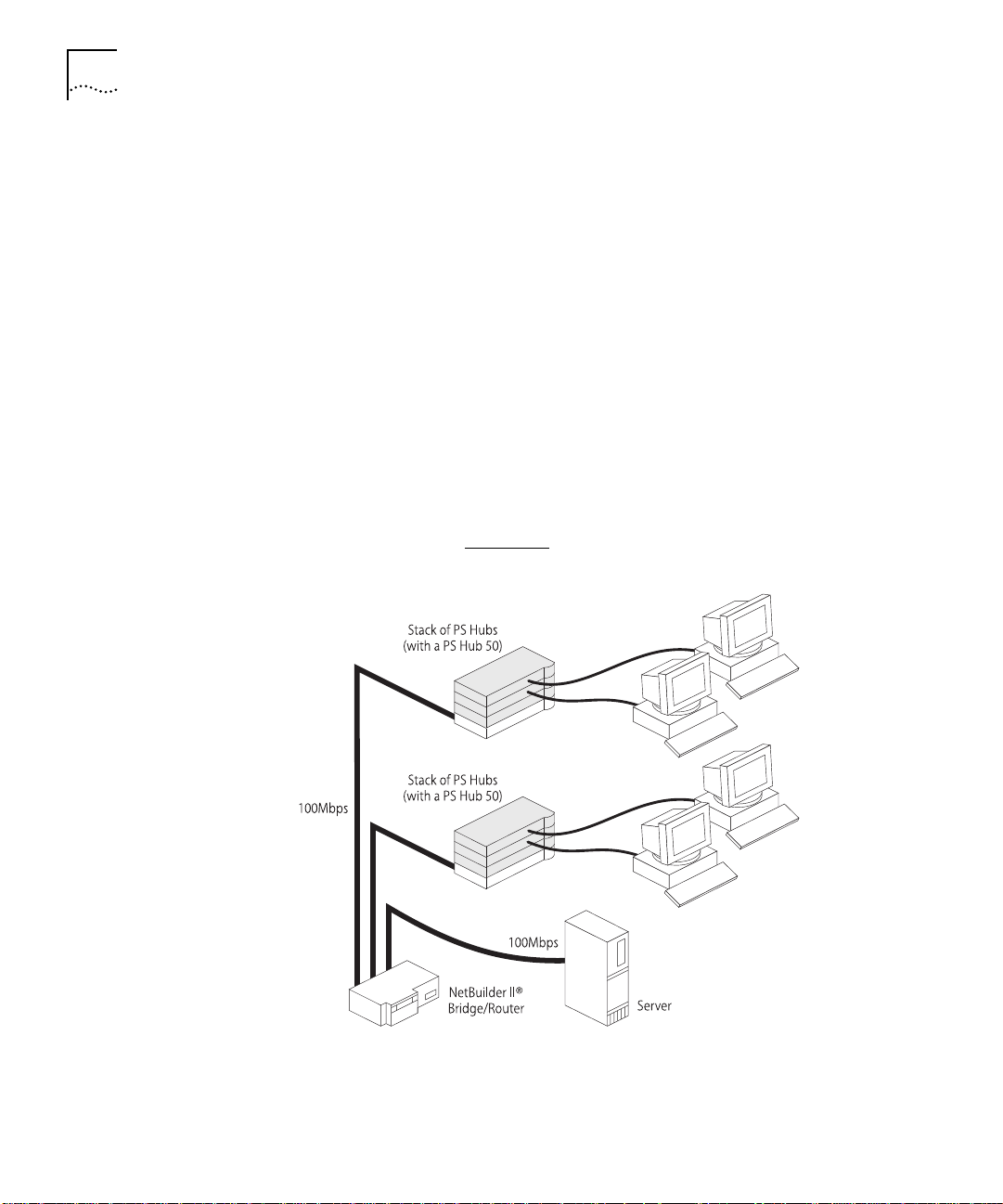
Figure 1-4
(the network is a stack of SuperStack
shows how PS Hubs can be added to an existing network
®
II Hub 10 units in this example).
The hubs create more ports now, and allow for further growth in the
future. The PS Hubs are connected to a switch so that communication
between them is controlled.
DUA1640-5AAA02
Figure 1-4
Expanding an Existing Network
Page 24
1-6
C
HAPTER
1: A
BOUT THE
PS H
UB
Migrating to Higher
Performance
The PS Hub is ideal for migrating your existing network to a higher
performance network. Using its internal segments (each running at
10Mbps), you can build up separate workgroups within a PS Hub stack.
Having a PS Hub 50 in your PS Hub stack can extend the flexibility of
your stack:
The PS Hub 50 has an internal switch (called a
■
segment switch
)
which can interconnect the segments in the stack so that the
workgroups on the segments can communicate.
The PS Hub 50 has a transceiver module slot which can be fitted
■
with a 10Mbps or 100Mbps 3Com transceiver module, providing
you with the option of having a 100Mbps network connection, for
example 100BASE-TX or 100BASE-FX. This allows you to connect to
100Mbps networks or network equipment, for example a server.
For information on the differences between the PS Hub 40 and the
PS Hub 50, refer to Chapter 2
.
Figure 1-5
Migrating to a Higher Performance Network
DUA1640-5AAA02
Page 25
Workgroups 1-7
Workgroups
Workgroups?
What Are
An important feature of the PS Hub is that you can create
workgroups
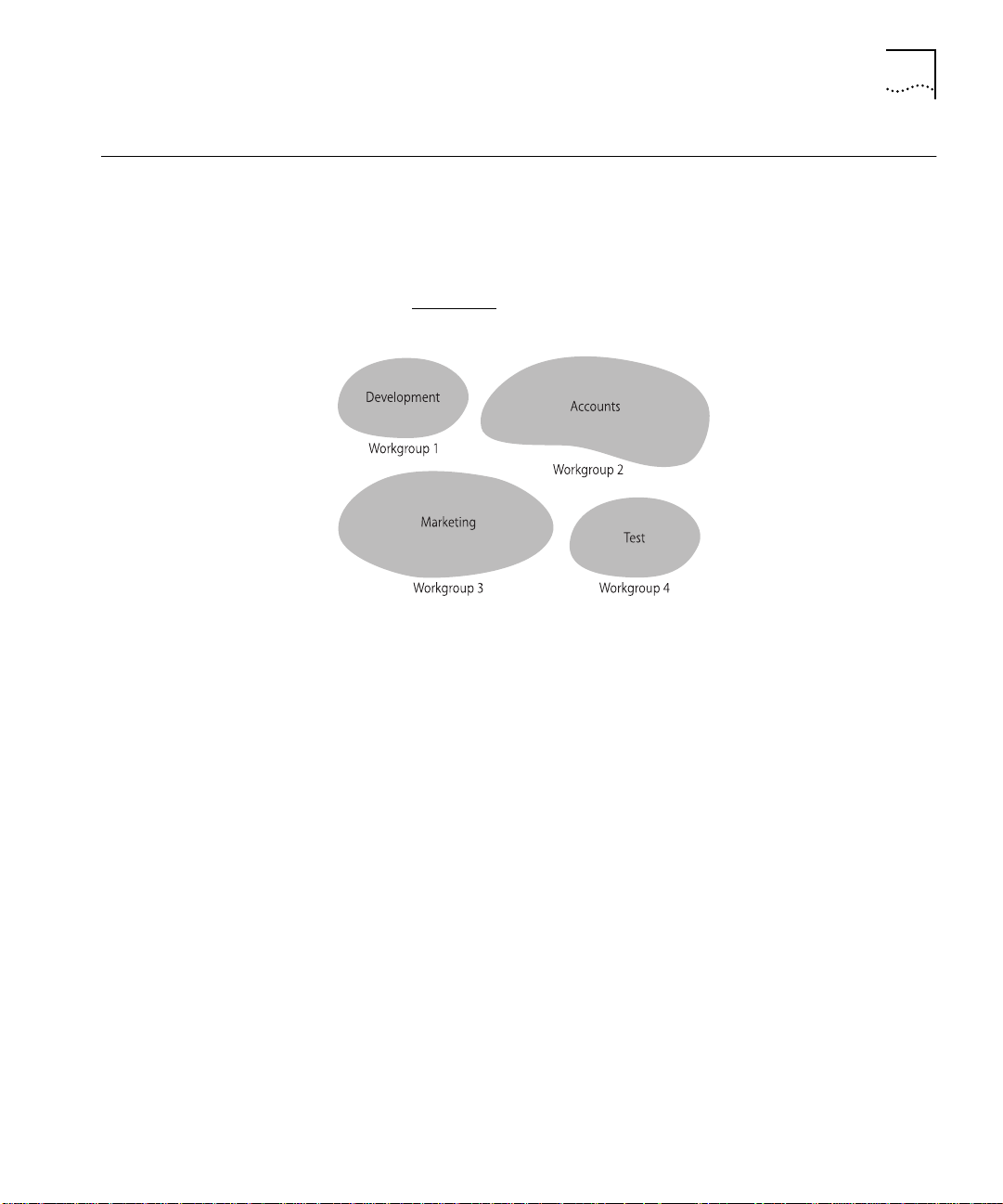
A good way to organize your network is to neatly group your users in
a logical way, called workgroups. For example, if your office consists of
four departments, you can mirror this by having four workgroups, as
shown in Figure 1-6
Figure 1-6
Workgroups
.
You can keep these workgroups separate from each other so that the
communication is contained within each workgroup, or you can use
the switching functionality of a PS Hub 50 to enable communication
between the workgroups.
.
DUA1640-5AAA02
The workgroups are similar to the structure of your office, so it is easy
for you to make changes to your network; adding and removing users,
and moving users between workgroups.
The rest of this section describes how you can build up workgroups
using your PS Hub.
Page 26
1-8
C
HAPTER
1: A
BOUT THE
PS H
UB
Segments and
Port Switching
The PS Hub has four separate internal repeaters (called
segments
)
which you can use to create your workgroups. You can switch the
hub’s ports to any of these segments (called
port switching
). With the
segments and port switching, you can easily create your workgroups.
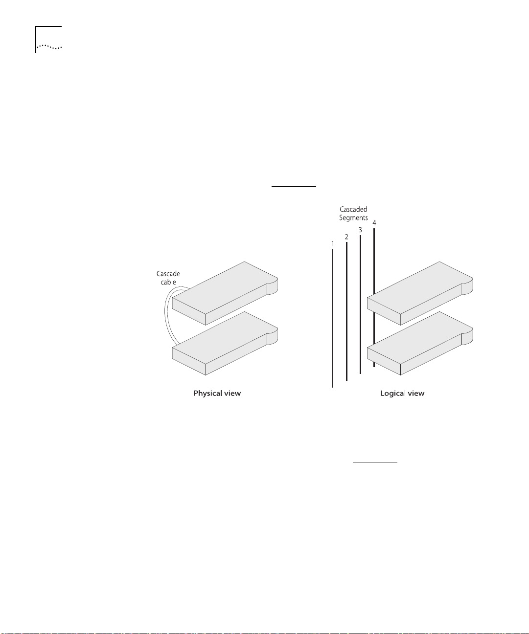
How the PS Hub Segments Work
In a stack of PS Hubs, four segments are carried between the hubs by
the cascade cables. These segments are four separate networks internal
to the stack, as shown in Figure 1-7
.
Figure 1-7
Cascaded Segments
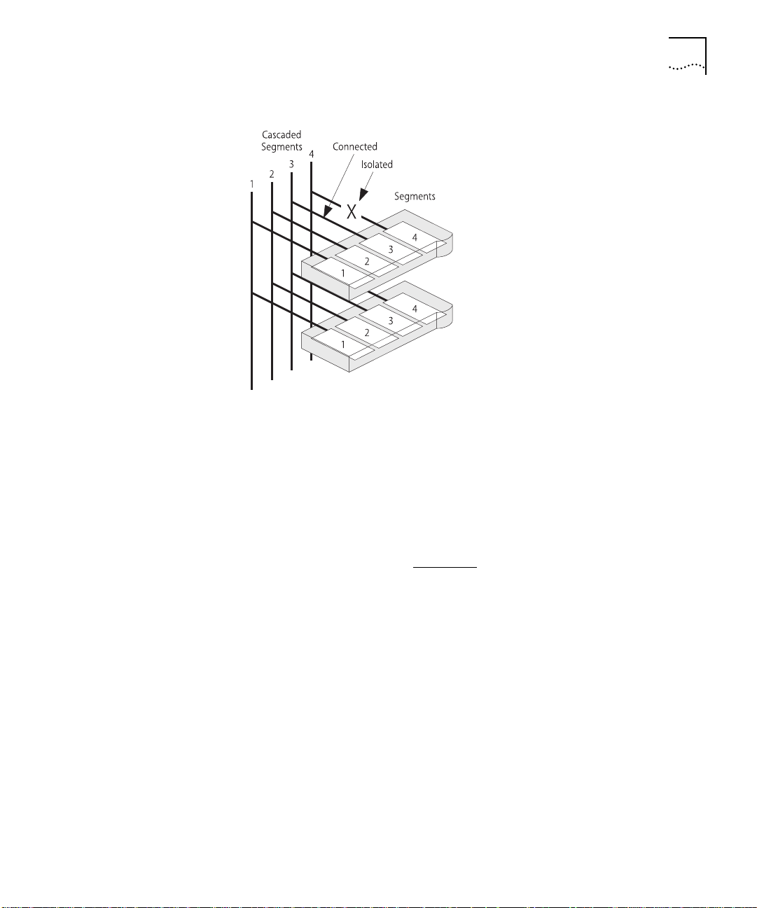
Each PS Hub has four internal segments. These segments are separate
internal repeaters, and can connect to or remain isolated from their
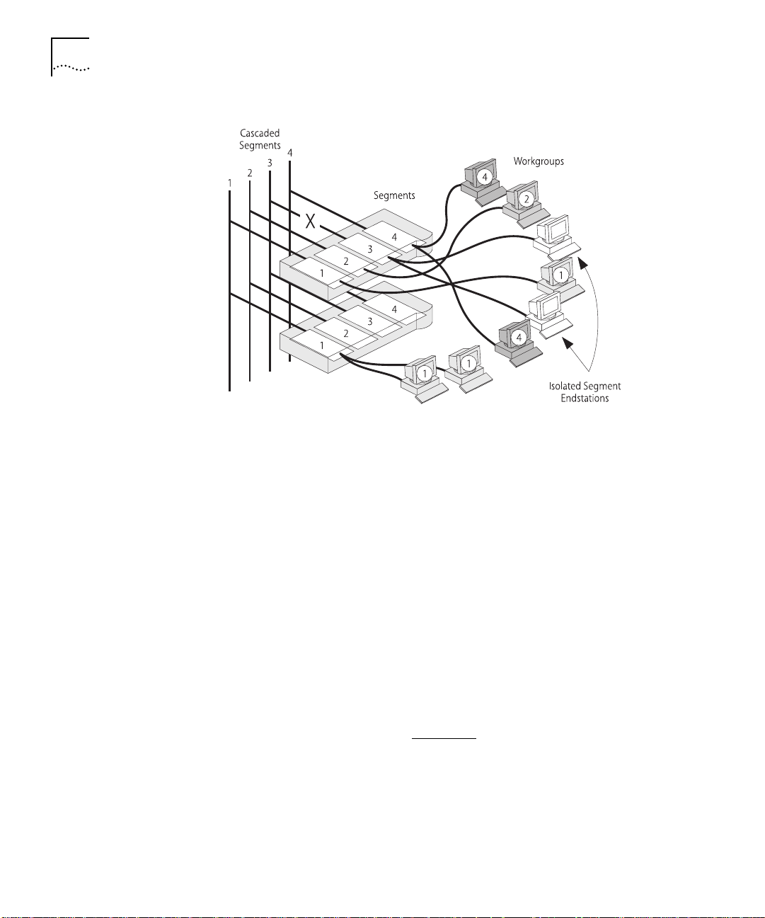
associated cascaded segments, as shown in Figure 1-8
.
DUA1640-5AAA02
Page 27
Workgroups 1-9
Figure 1-8
Internal Segments
You use management software to configure the segments. You can:
Connect and isolate the segments from their associated cascaded
■
segments.
Switch the ports between the segments (port switching).
■
The ability to configure the segments allows you to create flexible
workgroups, as shown in Figure 1-9
, which can change and grow with
your needs.
DUA1640-5AAA02
Page 28
1-10
C
HAPTER
1: A
BOUT THE
PS H
UB
Figure 1-9
Workgroups
Benefits of Segments and Port Switching
The key to port switching is that you are not restricted by physical
connections, and can create location and technology independent
networks. This has many benefits:
You can move users between segments easily — You simply switch
■
the ports between the segments, as necessary, using management.
The segments are carried throughout the stack — You can add
■
hubs, when necessary, to extend the existing cascaded segments.
Each segment is more efficient — Local network traffic is contained
■
within each cascaded segment, so they avoid congestion from the
other segments. You can increase the efficiency by using load
balancing to configure the segments so that traffic is distributed
evenly across them. You can use the web interface or Quick Config
Manager to configure load balancing. For information on how load
balancing works, refer to Chapter 4
Total bandwidth is higher — Each segment runs at 10Mbps, so four
■
.
separate segments per hub provides a total of 40Mbps per hub.
Configuration of the segments can be performed remotely — As
■
users are moved between the segments by port switching, no
physical changes have to be made.
DUA1640-5AAA02
Page 29

Workgroups 1-11
There is extra security — Hub segments can be isolated from the
■
cascaded segments, so that only workstations on the same hub
segment can communicate with each other.
Port switching enables you to extend any existing workgroups you
■
may have, across the whole network infrastructure, including
shared Ethernet workgroups.
DUA1640-5AAA02
Page 30
1-12
C
HAPTER
1: A
BOUT THE
PS H
UB
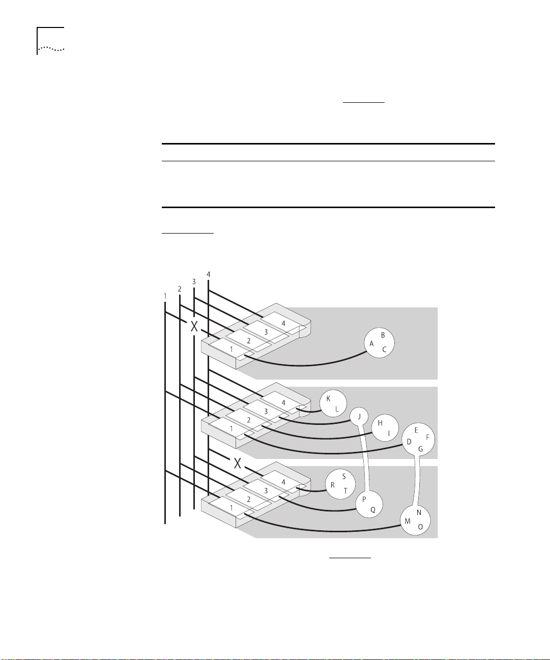
Workgroup Example
This example shows how a stack of three PS Hubs can easily create a
network with the desired workgroups. Table 1-1
shows how the users
are grouped:
Table 1-1
Hub Development Accounts Marketing Test Isolated
Top A, B, C
Middle D, E, F, G H, I J K, L
Bottom M, N, O P, Q R, S, T
Figure 1-10
Groupings
shows how the required workgroups are created using a
stack of PS Hubs.
Figure 1-10
Workgroup Example (see
Tab le 1- 1
)
DUA1640-5AAA02
Page 31

Workgroups 1-13
Your workgroups are easy to change. Table 1-2 shows several changes
to the example, and the simple actions needed to implement the
changes:
Table 1-2
Change to workgroups Hub affected
A, B and C become part of
Development (cascaded segment 1)
R, S and T become part of Marketing
(cascaded segment 3)
U and V are new users on the bottom
hub and become part of Accounts
Figure 1-11
Changes to the Workgroups
Top Reconnect segment 1
Bottom Switch ports for R, S
Bottom Switch new ports for
shows the workgroups after the changes have been made.
Action to implement
change
to cascaded segment 1
and T to segment 3
U and V to segment 2
DUA1640-5AAA02
Figure 1-11
Workgroup Example After Changes
Port switching is independent of the physical connections, so it can be
made quickly and easily, through either local or remote management.
Page 32

1-14
C
HAPTER
1: A
BOUT THE
PS H
UB
If one of the PS Hubs in the example is a PS Hub 50, you can enable
communication between the four cascaded segments in the stack, so
that your workstations can communicate across the segments.
For information on the PS Hub 50, refer to “PS Hub 50” on page 2-2
For information on the segment switch in the PS Hub 50, refer to
“Segment Switch” on page 2-2
.
.
For information on load balancing, refer to Chapter 4
.
DUA1640-5AAA02
Page 33

2
H
OW THE
This chapter contains the following topics:
■ An overview of the differences between the PS Hub 40 and
PS Hub 50
■ How the PS Hub 50 segment switch and transceiver module slot
work
PS H
UBS
D
IFFER
Overview
This chapter describes how the PS Hub 40 and PS Hub 50 are different.
However, they are both part of the PS Hub family and have many
similar features. For information on these common features, refer to
“Features” on page 1-2
Tab le 2-1
Table 2-1
Features PS Hub 40 PS Hub 50
Has the hub got an internal segment switch? No Yes
Number and type of transceiver module slots 2 x 10Mbps 1 x 10Mbps or
Apart from the differences shown in Table 2-1
same features.
shows a summary of the differences between the PS Hubs:
Differences Between the PS Hubs
.
100Mbps
, the PS Hubs have the
Page 34

2-2
C
HAPTER
2: HOW
THE
PS H
UBS DIFFER
PS Hub 40
PS Hub 50
Segment Switch
The PS Hub 40 has two 10Mbps transceiver module slots. When fitted
with transceiver modules, these ports can be port switched to any of
the hub’s four internal segments.
For information on what transceiver modules you can use, refer to
“Using Transceiver Modules” on page 3-12
.
The main feature of the PS Hub 50 over the PS Hub 40 is that it has an
internal
segment switch
.
The segment switch is an additional part of the PS Hub 50 which links
the stack’s four cascaded segments. It provides switching between the
four cascaded segments in the stack, so that the workstations on those
cascaded segments can communicate across the segment switch.
Using management, you can connect or isolate the segment switch
from the cascaded segments, as shown in Figure 2-1
.
Figure 2-1
The PS Hub 50 Unit’s Segment Switch
DUA1640-5AAA02
Page 35

PS Hub 50 2-3
How Does the Segment Switch Work?
Information is passed around the network in small units, called
These packets contain various Ethernet addresses called
MAC addresses
packets
which are unique addresses that are permanently stored within each
piece of network equipment:
Source address — the MAC address of the equipment that sent the
■
packet.
Destination address — the MAC address of the equipment that the
■
packet is intended for.
The network adapters in your workstations have a MAC address which
is used to identify the workstations on the network. An example of a
MAC address is ‘08004e0849d1’.
Using the source addresses, the PS Hub 50 unit’s segment switch can
which workstations are connected to each of the cascaded
learn
segments. This information is stored in a
switching database
, which is a
list containing each source address together with the associated
cascaded segment. Using this database, the segment switch can then
selectively pass future packets to the relevant cascaded segment.
.
,
DUA1640-5AAA02
When the switch database is full, no new addresses are learnt. The
segment switch regularly removes unused learnt addresses from the
switch database (known as
), if they have not been used after
ageing
30 minutes (the ageing period). Using the web interface, you can make
address entries permanent so that they are not removed by the ageing
process.
The segment switch has the following features:
Support for multiple PS Hub 50 units in the same stack.
■
Switch database with a capacity of 500 workstation addresses.
■
Self-selecting switch mode:
■
If a 100Mbps transceiver module is fitted, the segment switch is
■
in
(Local Office Interconnect) mode — The 100Mbps
LOI
transceiver module port behaves like a
downlink
port. A
downlink port is a port that is typically connected to the rest of
the network. All packets with an unknown destination address
are forwarded to the downlink port only, and addresses are not
learnt on this port.
Page 36

2-4
C
HAPTER
2: HOW
PS H
THE
UBS DIFFER
If a 10Mbps transceiver module is fitted or no transceiver module
■
is fitted, the segment switch is in 802.1d Bridge mode — All
packets with an unknown destination address are forwarded to
all ports.
Default Settings
The PS Hub 50 comes ready to use with all of the cascaded segments
connected to its segment switch (the default configuration). To isolate
and connect segments, and to control the way the hub’s segment
switch works, you must manage the hub. For information on
management, refer to Chapter 5
.
Multiple PS Hub 50 Units in a Stack
The PS Hub 50 has been designed so that you can have multiple
PS Hub 50 units in the same stack. You may want to do this so that the
cascaded segments are always switched, when:
■
The stack is split.
■
One of the PS Hub 50 units is removed or fails.
You could have two PS Hub 50 units in a stack of PS Hubs, one at the
top and one at the bottom.
PS Hub 50 units automatically detect each other in the stack and
configure themselves so that one of the hubs becomes the
, and the segment switches in all the other hubs are disabled.
switch
active
This is to reduce the possibility of loops in the stack. If a PS Hub 50 is
removed from the stack or fails, the other hubs reconfigure themselves.
The process for detecting and reconfiguring is as follows:
If one hub has a 100Mbps transceiver module fitted, that hub becomes
1
the active switch.
If more than one hub has a 100Mbps transceiver module fitted but
2
only one has a link (is receiving information through its transceiver
module port), that hub becomes the active switch.
If all PS Hub 50 units appear to be equal, the hub with the lowest unit
3
number (the one nearest the bottom of the stack if connected
correctly) becomes the active switch.
Only the active switch learns addresses and adds them to its switch
database.
DUA1640-5AAA02
Page 37

PS Hub 50 2-5
Fast Ethernet Resilience
The process that chooses the active switch (when there are multiple
PS Hub 50 units in a stack) enables you to have a Fast Ethernet resilient
link in your stack.
Figure 2-2
shows a stack of two PS Hub 50 units, both with 100Mbps
transceiver modules. Both transceiver modules have a connection and
appear to be equal, so the bottom unit’s segment is the active segment
switch (and that transceiver module is used). If the connection to the
bottom unit’s transceiver module fails, the stack reconfigures so that
the top unit’s segment switch becomes the active segment switch.
Figure 2-2
Fast Ethernet Resilience
DUA1640-5AAA02
Page 38

2-6
C
HAPTER
2: HOW
THE
PS H
UBS DIFFER
PS Hub 50
Transceiver Module
Slot
The PS Hub 50 unit’s transceiver module can be fitted with a 3Com
10Mbps or 100Mbps transceiver module. The operation of the
transceiver module slot differs when using either a 10Mbps or
100Mbps transceiver module:
Packets with an unknown destination address are dealt with
■
differently by the segment switch, refer to “How Does the Segment
Switch Work?” on page 2-3
The configuration of the transceiver module port is different.
■
.
For information on what transceiver modules you can use, refer to
“Using Transceiver Modules” on page 3-12
.
Using a 10Mbps Transceiver Module
When a 10Mbps transceiver module is used, the PS Hub 50 allows you
to port switch it to any of the hub’s four internal segments (by default
it is switched to segment 1), as shown in Figure 2-3
.
Figure 2-3
Using a 10Mbps Transceiver Module
DUA1640-5AAA02
Page 39

PS Hub 50 2-7
Using a 100Mbps Transceiver Module
When a 100Mbps transceiver module is used, the PS Hub 50
automatically connects it to the hub’s internal segment switch, as
shown in Figure 2-4
.
Figure 2-4
Using a 100Mbps Transceiver Module
Using a 100Mbps transceiver module to provide a 100Mbps network
connection, gives you several options:
You can have a fast downlink to a network server or the rest of
■
your network.
You can connect a 100Mbps network to your 10Mbps network,
■
allowing you to migrate to a faster network in the future.
With multiple PS Hub 50 units, you can have a Fast Ethernet resilient
link in your stack, refer to “Fast Ethernet Resilience” on page 2-5
.
DUA1640-5AAA02
Page 40

2-8
C
HAPTER
2: HOW
THE
PS H
UBS DIFFER
DUA1640-5AAA02
Page 41

3
U
SING THE
This chapter contains the following topics:
■ Description of the hub’s LEDs and ports
■ Positioning the hub
■ Rack and wall mounting the hub
■ Connecting PS Hubs together
■ Connecting workstations and other equipment to the hub
■ Spot Checks
PS H
UB
LEDs and Ports
Figure 3-1 (over the page) shows the hub’s diagnostic LEDs and easy to
use ports. This diagram also appears on the Quick Reference Guide.
The LEDs:
■ Show you how the hub and its ports are operating
■ Show you how the hub’s segments are operating
■ Alert you to a potential problem with your network
The different types of ports are used for:
■ Connecting workstations and other equipment to your hub
■ Connecting your hub to other PS Hubs, to form a stack
■ Connecting a management station to your hub for local
management
CAUTION: Only connect a SuperStack
the Redundant Power System socket.
Do not remove the transceiver module blanking plate with the power
still connected.
®
II Redundant Power System to
Page 42

3-2
C
HAPTER
3: U
SING THE
PS H
UB
Figure 3-1
The LEDs and Ports (the PS Hub 40 is shown)
DUA1640-5AAA02
Page 43

LEDs and Ports 3-3
DUA1640-5AAA02
Page 44

3-4
C
HAPTER
3: U
SING THE
PS H
UB
Before You Start
What Other
Equipment Is
Needed?
Your PS Hub comes with:
One power cord for use with the PS Hub
■
Four standard height and two reduced height self-adhesive rubber
■
feet
Two mounting brackets and four screws
■
Four self-adhesive labels
■
One CD-ROM featuring:
■
The 3Com serial web utility (SLIP driver for Windows ‘95)
■
An agent upgrade utility
■
Transcend® Quick Configuration Manager for Windows
■
Transcend® Load Balancing Tool
■
Online help
■
Online versions of this user guide
■
A Warranty Registration card for you to fill out and return
■
A Quick Reference Guide
■
You may need to get some cables and other equipment for connecting
your workstations and other hubs to the PS Hub. Your supplier should
stock these cables and equipment. For information on how the cables’
pins are connected, refer to “Cabling” on page A-3
.
Connecting Workstations
To connect workstations to your hub, you need:
One ‘Straight-through’ 10BASE-T cable for every workstation.
■
We recommend you use shielded 10BASE-T cables. The maximum
length you can use is 100m (328ft).
In order to comply with the 10BASE-T standard, ports designed for
workstation connections have been marked with the graphical symbol
‘x’. This denotes a crossover in the port’s internal wiring, for example
1x, 2x, 3x...
For information on connecting workstations to your hub, refer to
“Connecting Workstations to Your Hub” on page 3-11
.
DUA1640-5AAA02
Page 45

Before You Start 3-5
Connecting PS Hubs (Stacking)
To connect another PS Hub 40 or PS Hub 50 to your hub using the
cascade ports, you need:
One cascade cable for each additional hub.
■
Cascade cables have resilience built into them which protects the
internal segments and management communication that is carried
between the hubs in the stack. You can increase this resilience by using
SuperStack II PS Hub Hot Swap Cascade Units with the cascade cables,
refer to “Using Hot Swap Cascade Units” on
page 3-15
.
Cascade cables are available from your supplier in a variety of lengths,
refer to “Cascade Connections” on page A-6
. For information on
connecting another PS Hub to your hub, refer to “Connecting PS Hubs
Together (Stacking)” on page 3-12
.
Connecting Different Hubs and Stacks
To connect different hubs or stacks to your hub, you need:
One ‘Straight-through’ 10BASE-T cable for each unit or stack —
■
if using the last port (port 12 or 24) and the MDI/MDIX switch.
DUA1640-5AAA02
One ‘Crossover’ 10BASE-T cable for each unit or stack — if using
■
any 10BASE-T port other than port 24.
For information on connecting a hub or stack to your hub, refer to
“Connecting Different Hubs and Stacks to Your Hub” on page 3-16
Connecting Management Equipment
For information on what equipment you need to manage the hub,
refer to Chapter 5
.
.
Page 46

3-6
C
HAPTER
3: U
SING THE
PS H
UB
Positioning the
PS Hub
Using the Rubber Feet
When installing your PS Hub, ensure that:
It is accessible and cables can be connected easily.
■
It is out of direct sunlight and away from sources of heat.
■
Cabling is away from power lines, fluorescent lighting fixtures, and
■
sources of electrical noise such as radios, transmitters and
broadband amplifiers.
Water or moisture cannot enter the case of the unit.
■
Air flow around the unit and through the vents in the side of the
■
case is not restricted. We recommend you provide a minimum of
25.4mm (1in.) clearance.
Free standing hubs are not stacked more than six high, and that
■
cables are supported so that they cannot pull the stack over.
No objects are placed on top of any hub or stack.
■
Four standard height and two reduced height self-adhesive rubber feet
are supplied with the hub.
Do not apply the feet if you intend to rack or wall mount the hub.
Usage of the feet depends on where the PS Hub is placed:
If the hub is going to be placed on top of a flat surface or another
■
PS Hub, use the four standard height feet.
If the hub is going to be placed on top of a LinkBuilder® FMS™ II
■
hub or other SuperStack II unit, use two standard height feet
towards the front, and the two reduced height feet towards the
rear.
CAUTION: If the hub is to be part of a free standing stack, apply the
feet to each marked corner area on the underside of the hub. If the
free standing stack contains different size hubs, ensure that the larger
hubs are at the bottom of the stack.
DUA1640-5AAA02
Page 47

Using the Labels 3-7
Using the Labels
A sheet of four labels is supplied with the hub. Some labels have
already been attached to the hub.
The labels on the bottom of the hub show:
The product number, serial number and MAC (Ethernet) address of
■
the hub.
The safety approvals to which the hub conforms.
■
The labels on the rear of the hub show:
The product number of the hub.
■
The power safety information.
■
The four labels left on the sheet are for you to use as necessary.
Depending on how you are going to position the hub, you may want
to stick the labels in a more accessible place; on the top or on the front
of the hub, for example. All four labels have the name, product
number, serial number and MAC (Ethernet) address of the hub printed
on them.
CAUTION:
Do not stick the labels over any of the vents on the sides of
the hub.
DUA1640-5AAA02
Page 48

3-8
C
HAPTER
3: U
SING THE
PS H
UB
Rack and Wall Mounting
Rack Mounting
Two mounting brackets and four screws are supplied with the hub.
These are used for rack mounting and wall mounting the hub.
CAUTION: Disconnect all cables from the hub(s) before continuing.
Remove the self-adhesive rubber feet from the underside of the hub,
if already fitted.
The hub is 1U high and fits a standard 19in. rack.
To rack mount the hub:
Place the hub the right way up on a hard, flat surface with the front
1
facing towards you.
Locate a mounting bracket over the mounting holes on one side of the
2
hub, as shown in Figure 3-2.
Figure 3-2
Insert the two screws and fully tighten with a suitable screwdriver.
3
Repeat the two previous steps for the other side of the hub.
4
Insert the hub into the 19in. rack and secure with suitable screws
5
Locating the Brackets for Rack Mounting
(not provided).
DUA1640-5AAA02
Page 49

Rack and Wall Mounting 3-9
Wall Mounting
You can wall mount up to two hubs.
To fit the brackets to one hub, for wall mounting:
Place the hub the right way up on a hard, flat surface with the front
1
facing towards you.
Locate a mounting bracket over the mounting holes on one side of the
2
hub, as shown in Figure 3-3.
Figure 3-3
Insert the two screws and fully tighten with a suitable screwdriver.
3
Locating the Brackets for Wall Mounting One Hub
DUA1640-5AAA02
Repeat the two previous steps for the other side of the hub.
4
To fit the brackets to two hubs, for wall mounting:
Stack the hubs the right way up on a hard, flat surface with the front
1
facing towards you.
Locate two mounting brackets over the mounting holes on one side of
2
the hubs, as shown in Figure 3-4.
Page 50

3-10
C
HAPTER
3: U
SING THE
PS H
UB
Figure 3-4
Insert the three screws and fully tighten with a suitable screwdriver.
3
Repeat the two previous steps for the other side of the hubs.
4
Locating the Brackets for Wall Mounting Two Hubs
To wall mount the hub(s):
Ensure that the wall you are going to use is smooth, flat, dry and
1
sturdy. If necessary, attach a piece of plywood securely to your wall.
Ensure that the plywood is large enough to mount the hub(s) on.
Position the hub(s) against the wall (or plywood) ensuring that the
2
ventilation holes face sideways.
Mark on the wall the position of the screw holes for both wall
brackets. Drill the four holes.
Using suitable fixings and screws (not provided), attach the hub(s)
3
securely to the wall (or plywood).
DUA1640-5AAA02
Page 51

Connecting Workstations to Your Hub 3-11
Connecting Workstations to Your Hub
This section describes how to connect workstations to the hub using
the 10BASE-T RJ45 ports.
WARNING:
Ensure you have read the Important Safety Information
section carefully before you start.
ACHTUNG:
Versichern Sie sich, daß Sie den Abschnitt mit den
wichtigen Sicherheitshinweisen gelesen haben, bevor Sie das Gerät
benutzen.
AVERTISSEMENT:
Assurer que vous avez lu soigneusement la section
de L’information de Sécurité Importante avant que vous commenciez.
CAUTION:
Always wait about 5 seconds between powering off and
powering on the hub, to ensure that the hub performs a full reset.
Connecting workstations to your hub is easy. Connect them using
10BASE-T cables to any of the hub’s 10BASE-T RJ45 ports. To connect a
10BASE-T cable, simply slot the connector into the relevant RJ45 port.
When the connector is fully in, its latch locks it in place. To disconnect
the cable, push the connector’s latch in and remove it.
The hub detects all port connections, so you can start using your
network immediately. When you need more ports, simply add more
PS Hubs.
DUA1640-5AAA02
In order to comply with the 10BASE-T standard, ports designed for
workstation connections have been marked with the graphical symbol
‘x’. This denotes a crossover in the port’s internal wiring, for example
1x, 2x, 3x...
If you are using the last port (port 12 or 24) to connect a workstation,
ensure the MDI/MDIX switch is set to MDIX.
Page 52

3-12
C
HAPTER
3: U
SING THE
PS H
UB
Using Transceiver
Modules
Depending on your hub, the PS Hub has one or two transceiver module
slots, providing a choice of media options.
PS Hub 40
The PS Hub 40 has two 10Mbps transceiver module slots that can be
fitted with 3Com 10Mbps transceiver modules.
CAUTION: The only transceiver modules that can be used in the
PS Hub 40 unit’s transceiver module slots are 3Com 10Mbps transceiver
modules.
You cannot use two AUI Transceiver Modules or Bridge MicroModules
at the same time.
PS Hub 50
The PS Hub 50 has one transceiver module slot that can be fitted with
a 3Com 10Mbps or 100Mbps transceiver module.
You cannot use an AUI Transceiver Module or Bridge MicroModule.
The operation of the transceiver module in the PS Hub 50 is
determined by the type of transceiver module you use; refer to “PS Hub
50 Transceiver Module Slot” on
page 2-6
.
Connecting
PS Hubs Together
(Stacking)
You can increase the number of ports in your network by connecting
additional PS Hub 40 and PS Hub 50 units to your hub, to form a
(this process is called
stacking
). The four cascaded segments are carried
stack
through the stack, enabling you to switch the ports on all of the hubs
between the four segments.
You can stack up to 10 units (if they are rack mounted) or six units
(if they are free standing).
CAUTION: Do not have a free standing stack of more than six hubs.
When you connect workstations and other equipment to the stack,
ensure that all cables are supported and cannot pull the stack over.
If installing the PS Hub in a stack of mixed SuperStack II units, the
PS Hub must be installed above the deeper units.
For conformance with Ethernet rules, you can only have four repeaters
in series. For a stack of more than one PS Hub, any path through the
stack counts as going through two logical repeaters.
DUA1640-5AAA02
Page 53

Connecting PS Hubs Together (Stacking) 3-13
About Cascade
Cables
Cascade cables are used to connect the PS Hubs to form a stack. These
cables carry the stack’s cascaded segments and distributed
management information; the stack will not work with any other
cables. Cascade cables are available from your supplier, and come in a
variety of lengths, refer to “Cascade Connections” on page A-6
.
You can use a maximum of 6m (19.6ft) of cascade cabling between the
top and bottom hubs in the stack.
Stack Resilience and Hot Swap Functionality
Cascade cables have built-in resilience and hot swap functionality:
Up to three units within the stack can be powered off without
■
affecting the operation of the other units in the stack.
The units within a stack automatically reconfigure when a unit is
■
added or removed from the stack.
However, if a cascade cable is disconnected, the stack splits into two
isolated stacks. The units within the stack(s) automatically reconfigure
when a cascade cable is connected or disconnected.
Hot Swap Cascade Units
You can increase the resilience of the stack by using 3Com Hot Swap
Cascade Units (3C16430) with the cascade cables. These units can be
fitted to any PS Hub and provide total hot swap functionality.
DUA1640-5AAA02
The stack is held together even if units fail or are removed, added, or
powered off. For more information on how the Hot Swap Cascade
Units work, refer to the documentation that accompanies them.
Hot Swap Cascade Units are available from your supplier, refer to
“Cascade Connections” on page A-6
.
Page 54

3-14
C
HAPTER
3: U
SING THE
PS H
UB
Using Cascade Cables
To connect PS Hubs together, using Cascade cables:
Position the units as required; rack mounting or wall mounting them as
1
necessary.
Starting with the bottom unit, using a cascade cable:
2
Connect the cable’s connector marked UP to the UP port on the
■
unit.
Connect the cable’s connector marked DOWN to the DOWN port on
■
the unit directly above it.
Secure the cable in place by tightening its captive screws as tight as
possible by hand.
Continue up the stack, repeating step 2 for each unit, as shown in
3
Figure 3-5.
DOWN
UP
Figure 3-5
DOWN
UP
Connecting PS Hubs Together
DUA1640-5AAA02
Page 55

Connecting PS Hubs Together (Stacking) 3-15
Using Hot Swap
Cascade Units
To connect PS Hubs together, using Hot Swap Cascade Units:
Position the units as required; rack mounting or wall mounting them as
1
necessary.
Connect the Hot Swap Cascade Units with cascade cables:
2
Connect the cables’ connectors marked UP to the UP ports on the
■
Hot Swap Cascade Units.
Connect the cables’ connectors marked DOWN to the DOWN ports
■
on the Hot Swap Cascade Units.
Secure the cables by tightening the cables’ captive screws as tight as
possible by hand.
Starting at the bottom, connect the bottom Hot Swap Cascade Unit to
3
the UP and DOWN port of the unit. Secure the Hot Swap Cascade Unit
in place by tightening its long captive screws as tight as possible by
hand.
Continue up the stack, repeating step 3 for each unit, as shown in
4
Figure 3-6.
DUA1640-5AAA02
Figure 3-6
DOWN
UP
DOWN
UP
Connecting PS Hubs Together Using Hot Swap Cascade Units
Page 56

3-16
C
HAPTER
3: U
SING THE
PS H
UB
Connecting Different Hubs and Stacks to Your Hub
You can connect the PS Hub to different hubs and stacks (for example
a stack of SuperStack II Hub 10 units), giving you flexibility when
creating a new network, or expanding an existing network.
In order to conform with Ethernet rules, you can only have four
repeaters in series. For a stack of more than one PS Hub, any path
through the stack counts as going through two logical repeaters.
Each of the PS Hub’s 10BASE-T ports are internally crossed (MDIX).
The type of cable and ports used must be correct for the connection to
work:
You can use ‘Straight-through’ 10BASE-T cable to connect a
■
crossover (MDIX) port to an uncrossed (MDI) port.
You can use ‘Crossover’ 10BASE-T cable to connect two crossover
■
(MDIX) ports.
The last port (port 12 or 24) on the PS Hub can be either crossed or
uncrossed. The MDI/MDIX switch affects the port’s state:
If the switch is IN, the port is uncrossed (MDI).
■
If the switch is OUT, the port is crossed (MDIX).
■
Figure 3-7 shows a SuperStack II Hub 10 connected to the PS Hub.
A ‘Straight-through’ cable is used, and one of the SuperStack II Hub 10
unit’s crossed (MDIX) ports is connected to port 24 on the PS Hub
(note that the MDI/MDIX switch is IN, so the port is uncrossed).
DUA1640-5AAA02
Page 57

Powering On the Units 3-17
Powering On the Units
Spot Checks
DUA1640-5AAA02
Figure 3-7
Switch
Correct Hub Connections Using the Port 24 and the MDI/MDIX
When you have connected all of your equipment together, you are
ready to use your network.
You can power on the unit or the units in the stack in any order, and
can make your port connections at any time. After powering on the
hub, its Power/Self Test LED flashes for a few seconds while the hub
performs its self test. Afterwards, the LED lights green. If it does not,
refer to “Solving Problems With the Hub” on page 8-2
.
Any information that you configure for the unit using management, is
retained when you power off the unit.
At frequent intervals, visually check that:
Case vents are not obstructed
■
Cabling is secure and not pulled taut
■
If you suspect there is a problem, refer to Chapter 8
.
Page 58

3-18
C
HAPTER
3: U
SING THE
PS H
UB
DUA1640-5AAA02
Page 59

4
L
OAD
This chapter contains the following topics:
■ An overview of load balancing
■ How load balancing works
B
ALANCING
Overview
The PS Hub has a very useful feature called load balancing which can be used to configure segments in a stack of PS Hubs. The aim of load balancing is to increase total throughput across the segments in a stack, providing more efficient segments.
As load balancing configures segments in a stack, you cannot perform
workgrouping at the same time. In effect, the segments participating in
load balancing are a single, high-capacity workgroup.
For load balancing to work properly, there must be either:
■ A PS Hub 50 in the stack
■ A switch connected to the hubs in the stack
Page 60

4-2
C
HAPTER
4: L
OAD BALANCING
How Does Load
Balancing Work?
The load balancing feature monitors the traffic levels in the stack. At
regular intervals or when it reaches a predefined traffic level (whichever
you have configured), the stack starts load balancing. Here are the
steps it performs:
The PS Hubs work out which internal segments and cascaded segments
1
are connected by a switch (either through the PS Hub 50 unit’s
segment switch or an external switch). It does this because the load
balancing feature will only move ports between segments that they
currently communicate with (so that no workstations become isolated).
Figure 4-1
shows an example of a stack (with a PS Hub 50) that is to
be load balanced. The segments that can be load balanced have been
indicated.
Figure 4-1
Example of Load Balancing
DUA1640-5AAA02
Page 61

The load balancing feature notes:
2
Performing Load Balancing 4-3
Using an External
Switch
Any ports or segments that have been
■
— Through
fixed
management you can fix ports and segments that you do not want
load balancing to move.
Any ports that are connected to external switches.
■
These segments and ports will not be moved by load balancing.
However, traffic generated by these ports and segments will still be
considered by the load balancing feature, when it works out what
other ports it will move.
The load balancing feature works out how it can configure the
3
segments. It attempts to:
Have frequently communicating ports on the same segment.
■
Reduce the total traffic utilization across the segments.
■
If some benefit will be gained from the new configuration, the load
4
balancing feature completes the operation by moving the ports
between the segments as required.
The best way to interconnect the cascaded segments in a stack of
PS Hubs is to use a PS Hub 50. However, if you want to connect two or
more segments using an external switch, you must connect the switch
to the PS Hub’s 10BASE-T or transceiver module ports and then port
switch those ports to the relevant segments.
Performing Load Balancing
DUA1640-5AAA02
For information on using your switch, refer to the documentation that
accompanies it.
You can configure the load balancing feature through management
(it is disabled by default). For information on initiating the load
balancing feature using the web interface, refer to “Load Balancing”
on page 7-20
. For information on setting it up using the Load
Balancing Tool (which is launched from within Quick Config Manager),
refer to “Load Balancing” on page B-18
.
Page 62

4-4
C
HAPTER
4: L
OAD BALANCING
DUA1640-5AAA02
Page 63

5
M
ANAGING THE
This chapter contains the following topics:
■ The management tasks you can perform
■ What you can use to manage your stack
■ How you can make a management connection to your stack
PS H
UB
Introduction
Network management is not required to make the PS Hub work, but
allows you to change the way it works and to monitor what is
happening to the segments and the rest of the network. There are
many features that can improve the operation of the hub or stack.
A stack of PS Hubs is treated as a single manageable entity, and the
management is distributed. This guide uses the word ‘
a stack of one or more PS Hubs, and ‘
to the piece of equipment you are using to manage the stack (for
example a computer).
If the stack is connected and configured as recommended, the bottom
hub in the stack is unit number 1, the next hub up is unit number 2,
and so on.
All PS Hubs must be running agent software version 2.00 or later for
them to have the functionality mentioned in this user guide (for
example the web interface, CLI and load balancing). However, PS Hubs
that are running earlier agent software are compatible with newer
PS Hubs but do not have the newer functionality.
You can use Quick Configuration Manager to see what versions of
management software are on the units in the stack, and to upgrade
the stack; refer to “Upgrading a Stack” on page B-28
management station
stack’ to refer to
’ to refer
.
Page 64

5-2
C
HAPTER
5: M
ANAGING THE
PS H
UB
Why Manage Your Stack?
With management, you can change and view the way the stack or
network operates in the following way:
Display a graphical representation for the stack to quickly view the
■
status of each hub and its ports.
Display general information for the stack or hubs.
■
Graphically display network information for the stack’s cascaded
■
segments.
Enable and disable ports, and switch them between segments.
■
Perform load balancing so that the traffic is distributed evenly across
■
the segments in the stack, resulting in more efficient segments.
Configure security for the ports, including specifying what
■
equipment is allowed to communicate through the ports on the
hub.
Set up resilience; specify a backup connection that takes over should
■
a main connection fail.
View statistics.
■
Configure the console port for connection to a modem.
■
Configure user management access levels.
■
Upgrade the management software in the stack with any future
■
agent software upgrade.
Configure the stack to send messages (called
■
network management application (for example, Transcend
) to an SNMP
traps
®
Enterprise Manager) if certain conditions arise — you cannot
configure this using the web interface.
Perform remote monitoring using RMON — not manageable using
■
the web interface or Quick Config Manager.
Restart the hub to refresh its statistics and use any new
■
configurations.
Initialize the hub to return it to its factory settings (IP information is
■
retained).
DUA1640-5AAA02
Page 65

How You Can Manage Your Stack 5-3
How You Can Manage Your Stack
Command Line
Interface
A stack of PS Hubs is treated as a single manageable entity, and the
management is distributed. Any network address information (IP
information) that you configure for a hub, can be used to access the
stack.
The PS Hub has two built-in management interfaces which you can
access locally (through the hub’s console port) or remotely (over the
network):
A Command Line Interface (CLI) — can be used to set up the stack
■
with network address information.
A web interface — provides easy management of the stack from
■
any suitable web browser.
There is also a management application called Transcend Quick
Configuration Manager, referred to as ‘
Quick Config Manager
’ in this
guide, that is supplied on the CD-ROM. It runs under Microsoft
Windows
®
and provides an easy-to-use graphical management system.
The PS Hub’s Command Line Interface (CLI) is a simple text-based user
interface which allows you to configure some network information for
your hub. The CLI provides just a subset of the web interface’s
functionality but is intended as a quick setup tool, to get your hub
ready for management over the network. You can use a Terminal or
Terminal emulator to access the CLI.
Web Interface
DUA1640-5AAA02
The PS Hub’s web interface provides easy management of the stack.
It behaves in a similar way to a web site on the World Wide Web in
that you access it using a web browser. You use its different pages to
change the network information in your stack and perform different
management tasks.
Page 66

5-4
C
HAPTER
5: M
ANAGING THE
PS H
UB
SNMP Network
Management
The web interface and CLI built into your PS Hub allow you to manage
the stack. However, as your network grows, you may need a more
powerful SNMP network management application that will control all
of your managed units and stacks. Whether your network is large or
small, its ongoing performance, growth and security are only as good
as its management system.
3Com produces a range of powerful graphical SNMP network
management applications (for example Transcend Enterprise Manager
for Windows) that give you total control over your entire 3Com
network from a single management station.
Using intelligent 3Com software distributed throughout the network,
3Com’s Transcend management applications support all of today’s
platforms and manage a wide variety of 3Com products.
For further information about which Transcend management
application can benefit your growing network, call your local sales
office; refer to Appendix E
.
DUA1640-5AAA02
Page 67

Methods of Management 5-5
Methods of Management
There are many ways you can connect your management station to the
stack, as shown in Figure 5-1. You can manage the stack:
Through the console port (known as
■
Using a web browser
■
Using a terminal emulator
■
Using a terminal
■
Using Quick Config Manager
■
Over the network (known as
■
Using an SNMP network management application
■
Using a web browser
■
Using a terminal emulator (over Telnet)
■
Using Quick Config Manager (Windows® ‘95 and Windows NT®)
■
in-band
out-of-band
management):
management):
If you are going to manage the stack over the network, the quickest
way to set it up with the necessary network information is to connect
to one of the PS Hubs locally and use the CLI.
DUA1640-5AAA02
Figure 5-1
Different Management Connections to the Stack
Page 68

5-6
C
HAPTER
5: M
ANAGING THE
PS H
UB
Requirements for
Managing Over the
Network
When managing your stack over the network, you must remember that
(regardless of your method of management):
The hub or stack must be correctly configured with IP information.
■
You must make a direct management connection through the
console port to do this (or use a BOOTP server).
IP addresses are unique, no two hubs must have the same IP address.
If you have no previous knowledge of IP, refer to “IP Addresses” on
page 5-7
.
If you have a BOOTP server, it can automatically assign your network
equipment, including the PS Hubs, with IP information so that it can be
communicated with and managed over the network. Refer to the
documentation that accompanies your BOOTP server for more
information.
Any IP information configured for a hub in a stack can be used to
■
access the whole stack. If the stack is physically split in two, the IP
information remains with the hub and is used by its half; the other
half has no IP information so it becomes unmanageable over the
network. You can configure more than one hub in a stack with IP
information. We recommend you do this for the top and bottom
hubs to obtain redundant management capabilities (should the stack
split).
IP must be correctly set up for your management station.
■
You can manage the hub or stack over the network, through any of
■
the ports. However, for the communication to work over the
network, the port through which your communication reaches the
stack must be connected to segment 1 (either directly or indirectly)
of the hub with the IP address configured. If you are going to use
load balancing to configure your segments, it is a good idea to fix
this port to segment 1.
You can manage a mixed stack of PS Hub 40 and PS Hub 50 units.
■
If you have multiple PS Hub 50 units, only one of the hubs’ segment
switch will be active, refer to “Multiple PS Hub 50 Units in a Stack”
on page 2-4
.
DUA1640-5AAA02
Page 69

Methods of Management 5-7
IP Addresses
If you are uncertain about what IP addresses to assign your equipment,
contact your network administrator.
To operate correctly, each device on your network (for example a hub
or management station) must have a unique IP address (if one is
configured). IP addresses have the format
n.n.n.n
where n is a decimal
number between 0 and 255. An example IP address is ‘191.1.1.8’.
The IP address can be split into two parts:
The first part (‘191.1’ in the example) identifies the network on
■
which the device resides.
The second part (‘1.8’ in the example) identifies the device within
■
the network.
If your network is internal to your organization only, you may use any
arbitrary IP address. We suggest you use addresses in the series
191.1.1.X where X is a number between 1 and 254. Use the default
SLIP address of 192.168.101.1.
If your network has a connection to the external IP network, you must
apply for a registered IP address. This system ensures that every IP
address used is unique; if you do not have a registered IP address, you
may be using an identical address to someone else and your network
will not operate correctly.
DUA1640-5AAA02
Obtaining a Registered IP Address
InterNIC Registration Services is the organization responsible for
supplying registered IP addresses. The following contact information is
correct at time of publication:
Network Solutions
Attn.: InterNIC Registration Service
505 Huntmar Park Drive
Herndon
VA 22070
USA
Telephone: (1) (703) 742 4777
World Wide Web site: http://www.internic.com/
Page 70

5-8
C
HAPTER
5: M
ANAGING THE
PS H
UB
Command Line Interface (CLI)
Through the Console
Port
The CLI allows you to configure a limited set of parameters for the
hub. You can access the CLI:
Through the console port
■
Over the network
■
This section has information on accessing the CLI. For more information
on using the CLI, refer to Chapter 6
Tab le E- 1
Table E-1
Data bits (character size) 8
Stop bit 1
Parity None
shows the settings for the hub’s console port.
Console Port Settings
.
You can access the console port through a direct local connection, or
you can set up a remote connection using a modem.
The terminal or management station (with the terminal emulator)
connected to the console port must use the same settings. By default,
the hub has auto-configuration enabled which will change the hub’s
console port settings to match those of the connected equipment and
automatically detect the baud rate (line speed). The hub can
auto-detect a maximum baud rate of 19200.
You need to use a null modem cable for connecting your terminal or
management station directly to the console port. This should be
available from your supplier. There are a variety of null modem cables
that you can use. For an example of one of these, refer to “Console
Cable” on page A-4
.
If you are using a modem in your setup, you need to use a modem
cable. For an example of one of these, refer to “Modem Cable” on
page A-5
. For information on setting up a connecting to the modem,
refer to the documentation that accompanies the modem.
DUA1640-5AAA02
Page 71

Command Line Interface (CLI) 5-9
To connect your equipment:
Connect the serial port on your terminal or management station to the
1
console port on the PS Hub, using a null modem cable.
Ensure that the terminal or management station’s serial port settings
2
match those of the console port on the PS Hub.
Using a Terminal Emulator
You can use the terminal emulator that comes with Microsoft Windows
to access the hub’s CLI:
Windows ‘95 and Windows NT (version 4 or later) have a program
■
called ‘HyperTerminal’.
Other versions of Windows have a program called ‘Terminal’.
■
For other types of management stations and operating systems, refer to
the documentation that accompanies your terminal emulator for
information on how to use it.
HyperTerminal
HyperTerminal can usually be found from the Windows
Programs, Accessories
. To start a HyperTerminal session (after
Start
menu, in
connecting to the hub’s console port):
Double-click on the ‘Hypertrm.exe’ icon to start the application.
1
The Connection Description dialog box appears.
Enter a dummy name in the
2
field and click OK.
Name
The Phone Number dialog box appears.
Select the serial port that you are using to connect to the hub, in the
3
Connect using
field.
The COM Properties dialog box appears.
Configure the data bits to ‘8’, stop bit to ‘1’, parity to ‘none’, and click
4
OK.
Click in the main HyperTerminal window and press [Return] several
5
times to start the communication.
DUA1640-5AAA02
Page 72

5-10
C
HAPTER
5: M
ANAGING THE
PS H
UB
Terminal
Terminal can usually be found from the
Accessories
program group. To start a Terminal session (after connecting
window, in the
Main
to the hub’s console port):
Double-click on the ‘Terminal’ icon to start the application.
1
If the Default Serial Port dialog box appears, select the serial port that
2
you are using to connect to the hub and click OK.
From the
3
Settings
menu in the main Terminal window, select
Terminal
Emulation.
The Terminal Emulation dialog box appears.
Select ‘DEC VT-100 (ANSI)’ and click OK.
4
From the
5
Settings
menu, select
Communications.
The Communications dialog box appears.
Configure the data bits to ‘8’, stop bit to ‘1’, parity to ‘none’, and click
6
OK.
Click in the main Terminal window and press [Return] several times to
7
start the communication.
DUA1640-5AAA02
Page 73

Command Line Interface (CLI) 5-11
Over the Network
Teln e t
You can access the CLI over a TCP/IP network using Telnet. To run
Telnet, you need a suitable terminal or management station running a
terminal emulator.
You can have multiple CLI management sessions at the same time. If a
connection is lost inadvertently, the connection is closed by the hub
after about 30 minutes of inactivity.
You can manage the hub or stack over the network, through any of
the ports. However, for the communication to work over the network,
the port through which your communication reaches the stack must be
connected to segment 1 (either directly or indirectly) of the hub with
the IP address configured.
Using a Telnet Terminal Emulator
You can use the Telnet terminal emulator that comes with Microsoft
Windows ‘95 (called ‘Telnet’) to access the hub’s CLI.
To open the Telnet session, you must specify the IP address of the hub
you want to manage. For other types of management stations and
operating systems, refer to the documentation that accompanies your
Telnet terminal emulator for information on how to do this.
The Telnet application (‘Telnet.exe’) can usually be found in the
Windows
directory on your PC. To start a Telnet session:
DUA1640-5AAA02
Run the ‘Telnet.exe’ application.
1
The Telnet application’s window appears.
From the
2
Connect
menu, select
Remote System
The Connect dialog box appears.
Type the IP address of the stack in the
3
for the
Click
4
field, and select ‘vt-100’ for the
Port
Connect.
.
Host name
TermType
field, select ‘telnet’
field.
Page 74

5-12
C
HAPTER
5: M
ANAGING THE
PS H
UB
Web Interface
Through the Console
Port
Over the Network
You can manage the PS Hub using its web interface. You can access
the web interface:
Through the console port
■
Over the network
■
This section has information on accessing the web interface. For more
information on using the web interface, refer to Chapter 7
.
You can access the web interface through the hub’s console port, using
a management station running
(Serial Line Interface Protocol).
SLIP
If your management station is running Windows ‘95, you must use the
3Com serial web utility that is supplied on the CD-ROM. This is a SLIP
driver that sets up SLIP access for web interface management. To install
and use the serial web utility, refer to
Appendix C
.
You need to use a null modem cable for connecting your management
station directly to the console port. This should be available from your
supplier. There are a variety of null modem cables that you can use. For
an example of one of these, refer to “Console Cable” on page A-4
.
You must have an IP stack on your management station, so that you
can manage over a TCP/IP network. An easy way to check this is that if
you have access to the Internet and can download web pages from it,
your management station has already got an IP stack.
Which Web
Browsers are
Supported?
For fully operational management, your web browser must support:
Java
■
Frames
■
HTML 3.2
■
Suitable web browsers are Netscape Navigator™ Version 3.0 or
Microsoft Internet Explorer Version 3.0.
Configuring Your Browser
Before you use your web browser to access the web interface, you
must make one small configuration change to it, so that it always
downloads the latest version of a page.
DUA1640-5AAA02
Page 75

To do this for Netscape Navigator:
Start Netscape Navigator.
1
Quick Config Manager 5-13
Quick Config Manager
From the
2
Options
menu, select
Network Preferences
.
The preferences dialog box appears.
Check the ‘Every Time’ checkbox.
3
Click OK.
4
To do this for Microsoft Internet Explorer:
Start Microsoft Internet Explorer.
1
From the
2
menu, select
View
Options
.
The Options dialog box appears.
Select the
3
Settings
Check the ‘Every visit to the page’ checkbox.
4
Click OK.
5
Advanced
.
tab, and in the Advanced property sheet click
You can manage the PS Hub using Quick Config Manager. You can
manage the hub:
Through the console port
■
Over the network — Windows ‘95 and Windows NT (version 4 or
■
later) only
Through the Console
Port
DUA1640-5AAA02
You can perform similar management functions using Quick Config
Manager as you can using the web interface.
You need to use a null modem cable for connecting your management
station directly to the console port. This should be available from your
supplier. There are a variety of null modem cables that you can use. For
an example of one of these, refer to “Console Cable” on page A-4
.
Connect one end of the null modem cable to the console port on the
hub, and the other to the serial (RS232) port on your management
station with Quick Config Manager installed.
Page 76

5-14
C
HAPTER
5: M
ANAGING THE
When using Quick Config Manager with Windows ‘95 and managing
through the console port, you must first disable FIFO buffers in the
Advanced Port Settings window in Windows ‘95. To do this:
PS H
UB
Over the Network
In the Windows ‘95 environment, select
1
Select (in turn):
2
Control Panel, System, Device Manager, Ports, COM1
(or whatever COM port you are using instead),
Advanced
.
My Computer
.
Port Settings
, and
The Advanced Port Settings window appears.
Uncheck the Use FIFO Buffers checkbox.
3
Click OK for the Advanced Port Settings window, and all of the
4
windows that were opened in order to access the window.
When you have made your connection and installed Quick Config
Manager, you are ready to manage the stack. Quick Config Manager
uses COM 1 as the default serial port on your management station.
If you want to change this, refer to “Running Quick Config Manager”
on page B-4
.
You must have an IP stack on your management station, so that you
can manage over a TCP/IP network.
You can manage the hub or stack over the network, through any of
the ports. However, for the communication to work over the network,
the port through which your communication reaches the stack must be
connected to segment 1 (either directly or indirectly) of the hub with
the IP address configured.
For information on installing and using Quick Config Manager, refer to
Appendix B
.
DUA1640-5AAA02
Page 77

U
SING THE
6
C
OMMANDLINEINTERFACE
This chapter describes how to use the Command Line Interface (CLI).
The CLI is a quick and simple interface that is built-in to the hub, which
allows you to enter various IP address settings, reset it and initialize it.
The web interface and Quick Config Manager can perform most of
the tasks that the CLI can do.
You would normally use the CLI if you have many hubs that you want
to set up quickly with IP address information, for eventual management
using an SNMP network management application.
Simple help is provided with each command in the Command Line
Interface.
Ensure that your terminal or management station (which has the
terminal emulator) has been appropriately set up for your particular
management method and that any necessary connections have been
made, refer to “Command Line Interface (CLI)” on page 5-8
.
If you have any problems using the CLI, refer to “Solving Problems
With the Command Line Interface” on page 8-3
.
Page 78

6-2
C
HAPTER
6: U
SING THE COMMANDLINEINTERFACE
Accessing the CLI
Initial Access
Logging On
By default, the hub automatically configures the baud rate of its
console port to operate with the connected management station or
terminal, provided the parity, stop bits and character size are identical
to the connected management station or terminal. You may need to
perform the wake-up procedure to initiate the communication. To do
this, press [Return] several times at the management station or
terminal.
The login sequence for the CLI begins as soon as the hub detects a
connection to its console port, or as soon as a Telnet session is started.
The login prompt
Login:
As the initial user, enter the default user name
[Return] at the
Password:
is displayed.
admin
and press
prompt. The first time you access the CLI,
the password is null.
We recommend that when you have accessed the stack, you change
the default passwords for the user levels (if you have not already done
so) by logging in as the different user levels.
At subsequent logins, enter your user name. If the user name is valid,
the
Password:
prompt appears. You must enter your password
correctly before you can continue with your management session.
If you have logged on correctly, the initial menu appears. If you have
not logged on correctly, the message
Incorrect password
appears
and the login sequence starts again.
DUA1640-5AAA02
Page 79

Accessing the CLI 6-3
Default User Names and Passwords
Tab le 6- 1
shows the default users that can access the hub and their
level of access. We recommend that setting a password is the first task
you carry out on the hub. Setting a password prevents unauthorized
management access to the hub or stack.
Logging Off
Table 6-1
User Name
monitor monitor Monitor — this user can view but not change all
manager manager Manager — this user can access and change
security security Security — this user can access and change all
admin Admin — this level is the same as Security
At the top level of the CLI, if you enter the command
Default Users
Default
Password
Access Level
manageable parameters
the operational parameters but not
special/security features
manageable parameters
logout
, the
management session is terminated.
Automatic Logout
As a security measure, a management session will be terminated if
there is a period of inactivity lasting longer than 30 minutes.
After the session has terminated, the first key that you press returns
you to the login prompt.
DUA1640-5AAA02
Page 80

6-4
C
HAPTER
6: U
SING THE COMMANDLINEINTERFACE
Using the CLI Menus
CLI Menu Structure
When you log on to the CLI correctly, the top-level menu is displayed,
as shown in Figure 6-1
number are shown (
Figure 6-1
Top-level menu
. The unit description, unit name and unit
PS Hub 50
and
Market ing(1 )
in this example).
Use the CLI by selecting options from this menu and from the others
below it. Each menu option is accompanied by a brief description of
what that option does.
Figure 6-2
shows the menu/command structure for the CLI.
Figure 6-2
CLI Menu Structure
From the top-level menu, you can access two sub-menus:
■
IP Menu
■
System Menu
— From here, you can configure IP parameters.
— From here, you can view system configuration,
configure CLI parameters, change your password, reset and
initialize the hub.
DUA1640-5AAA02
Page 81

Using the CLI Menus 6-5
Navigating the
Menus and Entering
Commands
You can navigate the menus using any of the following methods:
Following the menu hierarchy — at the
■
Select menu option:
prompt, type your selected menu name and press [Return].
The screen changes to show the next level of menus available or the
list of commands available within your selected menu.
Entering multiple menu names on the same line — if you are
■
familiar with the menu structure you can enter successive menus on
the same line at the
Select menu op tion:
prompt. For example,
to display the system configuration, the CLI would read:
Select menu option: system display
Abbreviated commands — for speedy navigation of the menus, you
■
need only enter enough characters to uniquely identify the menu
you want at the prompt. For example, to display system
configuration, the CLI would read:
Select menu option: sy di
As you navigate through the menus, the prompt changes to display
your current position in the hierarchy. For example, if you are in the
interface sub-menu of the system menu, ready to enter your next
option, the prompt reads:
Select menu option (system) :
DUA1640-5AAA02
Entering Commands
When you reach the menu level containing the specific command you
want to enter, you are prompted for a command name. Commands
can also be entered at the end of the menu string. Where applicable,
default values for commands are shown in parentheses after the
prompt. If you press the [Return] key for a command with such a value,
the hub continues to use that value.
Returning to the Previous Menu
You can return to the previous menu, by entering
at the prompt.
q
Returning to the Top-level Menu
You can return to the top-level menu by pressing the [Esc] key.
Obtaining Help
You can get help at any time by entering
at the prompt.
?
Page 82

6-6
C
HAPTER
6: U
SING THE COMMANDLINEINTERFACE
Quick Guide to the Commands
Tab le 6- 2 lists all of the commands available from the CLI and shows
you briefly what each one does and the pages in this chapter that
describes how to use the commands.
Table 6-2
Command What does it do?
define
(ip)
displa y
captur e
(system)
initia lize
invent ory
passwo rd
reset
unit
Commands
displa y
Sets IP and SLIP parameters
Displays IP and SLIP parameters
Enables/disables RMON Filter capture
Displays administration information for
the hub
Configures the stack back to default
settings
Lists the units in the stack
Changes the password of the current
user
Simulates powering off and powering
on the stack
Accesses another unit in the stack
Description can
be found on...
page 6-8
page 6-9
page 6-12
page 6-9
page 6-11
page 6-10
page 6-7
page 6-10
page 6-11
DUA1640-5AAA02
Page 83

Commands 6-7
Commands
Changing the
Password
The remaining sections in this chapter detail the management functions
that can be carried out from the CLI.
We recommend that setting a password is the first task you carry out
on the hub. Setting a password prevents unauthorized management
access to the hub or stack.
If you forget your password while logged out of the hub, refer to
“Solving Problems With the Command Line Interface” on
page 8-3
To set a new password or change an existing password:
At the top-level menu, enter:
1
system password
You are prompted for your old password:
2
Old password:
If this is the first time you are setting a password, press [Return]
without entering any text. If you already have a password set up, then
enter the password.
The prompt changes to show:
3
Enter new password:
Enter your new password. The prompt asks you to confirm your new
password by entering it again.
.
DUA1640-5AAA02
The CLI displays a message to tell you that your password has
successfully changed.
Page 84

6-8
C
HAPTER
6: U
SING THE COMMANDLINEINTERFACE
Setting the IP
Configuration
Before you can manage the hub over the network, you must assign it
an IP address and subnet mask. You may also need to enter a default
router (sometimes known as the default gateway) address. The default
router is the router (if you have one) which is used by the stack to
communicate with other networks. For serial management, you may
need to configure the SLIP address and SLIP subnet mask.
If you have no previous knowledge of IP, refer to “IP Addresses” on
page 5-7
. If you change any of these values, you may need to re-access
the hub using the new values.
To enter new IP settings:
At the top-level menu, enter:
1
ip interface define
You are prompted for the hub’s IP address:
2
Enter IP addr ess [0.0.0.0]:
Enter a valid IP address for the Hub.
You are prompted for the hub’s subnet mask:
3
Enter subnet mask [255.255.255.0]:
Enter a subnet mask.
You are prompted for a default router address:
4
Enter default gateway [0.0.0.0]:
Enter a default gateway address or press [Return] if it’s not needed.
You are prompted for a SLIP address:
5
Enter SLIP ad dress [192.168 .101.1]:
Enter a SLIP address or press [Return] if it’s not needed.
Finally, you are prompted for a SLIP subnet mask:
6
Enter SLIP subnet mask [255.255.255.0]:
Enter a SLIP subnet mask or press [Return] if it’s not needed.
DUA1640-5AAA02
Page 85

Commands 6-9
Viewing the
Configuration
You can use the display command to show current configuration
information for your hub or stack.
Displaying the Hub Configuration
At the top-level menu, enter:
system display
The CLI displays information similar to this example:
3Com PS Hub 50 (3C16450)
Unit Name: Marketing
Location: Top floor
Contact: James
Time since re set: 2 days, 3 h ours, 10 minute s
Operational Version: 1.00 Boot Version: 1.00
Hardware Vers ion: 1.00
Serial Number : 2103332
This information is in the hub’s MIB (Management Information Base)
and is read-only. You can change the Unit name, Location and Contact
using the web interface.
If a problem occurs and you need advice from your support
representative, you may be asked for some of the information shown
on this screen.
DUA1640-5AAA02
Displaying the IP Configuration
At the top-level menu, enter:
ip interface display
The CLI displays the IP address, subnet mask, default router address,
SLIP address and SLIP subnet mask for the hub.
Page 86

6-10
C
HAPTER
6: U
SING THE COMMANDLINEINTERFACE
Displaying the Stack Configuration
The inventory commands allows you to list the units in the stack.
At the top-level menu, enter:
system inventory
The CLI displays information similar to this example:
Position Description Name State
1 PS Hub 50 Marketing Un it Operati onal
2 PS Hub 40 Accounts Unit Operati onal
3 PS Hub 40 Development Un it Operati onal
Where:
Position — The position of the unit in the stack; if the stack is
■
correctly connected and configured as recommended, the bottom
unit in the stack is unit number 1, the next unit is unit number 2,
and so on.
Description — The type of unit.
■
Resetting the Stack
Name — The name that you have assigned to the unit.
■
State — The current operating status of the unit:
■
Unit Operational — Indicates that the unit is operating normally.
■
Unit Loading — Indicates that there is a process taking place,
■
for example a software upgrade.
Resetting the stack simulates powering off and powering on the stack.
You may want to do this if you want to reset the stack’s statistics
counters.
CAUTION: Performing a reset may cause some of the data being
transmitted over the network to be lost. It also clears the
non-permanent addresses in the PS Hub 50 unit’s switch database.
To reset the stack:
At the top-level menu, enter:
1
system reset
The CLI asks you to confirm the reset. Enter
2
or
if you want to stop the reset.
n
if you wish to proceed,
y
DUA1640-5AAA02
Page 87

Commands 6-11
Initializing the Stack
Configuring Another
Unit in the Stack
Initializing the stack causes it to return to its factory default settings.
You may want to do this if the stack has been previously used in a
different part of your network, and its settings are incorrect for its new
environment.
CAUTION:
Initializing the stack removes all configuration information
including security, resilient links and passwords. However, IP, SLIP and
default router information is retained to ensure you can continue
management communication with the stack over the network.
To initialize the stack:
At the top-level menu, enter:
1
system initialize
The CLI asks you to confirm the initialize. Enter
2
proceed, or
if you want to stop the initialize.
n
if you wish to
y
The stack’s passwords return to the default passwords.
The unit command allows you log on to another unit in the stack
without disconnecting from the current unit.
To configure another unit:
DUA1640-5AAA02
At the top-level menu, enter:
1
system unit
You are prompted for the unit’s number (note that the command
displays the number of the unit that you are currently configuring):
Select unit (1):
Enter the unit’s number.
2
When you have finished configuring the unit, simply log out to return
to the previous unit.
Page 88

6-12
C
HAPTER
6: U
SING THE COMMANDLINEINTERFACE
Enabling and
Disabling RMON
Filter Capture
You can enable or disable RMON Filter capture. By default this is
enabled. You may wish to disable this if you have no requirement to
perform RMON packet monitoring and wish to increase the security of
your network.
To configure RMON Filter capture:
At the top-level menu, enter:
1
system capture
Enable or disable RMON Filter capture as required.
2
DUA1640-5AAA02
Page 89

M
ANAGEMENT
U
SING THE
7
Accessing the
Web Interface
W
EBINTERFACE
This chapter describes how to use the web interface. If you have any
problems using the web interface, refer to “Solving Problems With the
Web Interface” on page 8-4
You can access the web interface for the stack either through the
console port or over the network. Ensure that your management
station has been appropriately set up for your particular management
method and that any necessary connections have been made, refer to
“Web Interface” on page 5-12
If you want to access the web interface through a serial link from a
Windows
a hub in the stack), you must use the 3Com serial web utility (SLIP
Driver); refer to Appendix C
Any number of people can access the web interface over the network,
at the same time. There is a password panel to prevent unauthorized
management of the stack.
®
‘95 management station (connected to the console port of
.
.
.
To access the web interface:
Start your web browser.
1
In the browser, select the option for opening a location.
2
Page 90

7-2
C
HAPTER
7: M
ANAGEMENT USING THE WEBINTERFACE
In the browser’s open location window or area, enter the web address
3
(Uniform Resource Locator) for the stack.
URL
The web address URL for a stack is in the format:
http://
nnn.nnn .nnn .nnn
/
Where
■
nnn.nnn.nnn.nnn
The SLIP address for the stack, which is ‘192.168.101.1’ by default,
is:
if managing through the console port
The IP address for the stack, if managing over the network
■
For example, to access a stack with an IP address of ‘191.1.1.8’ you
would enter:
http://191.1.1.8/
When the browser has located the stack, a password panel is displayed,
4
as shown in Figure 7-1
. Enter your user name and password as
requested.
Figure 7-1
Password Panel
If no passwords have been configured for the stack, the default
password for the security level of user is ‘security’. The user names and
passwords are the same as those that you use to access the CLI. For a
list of the user names and the default passwords, refer to “Default User
Names and Passwords” on page 6-3
.
We recommend that when you have accessed the stack, you change
the default passwords for the user levels (if you have not already done
so) by logging in as the different user levels.
If you forget your password while logged out of the stack, refer to
“Solving Problems With the Web Interface” on
page 8-4
.
DUA1640-5AAA02
Page 91

Accessing the Web Interface 7-3
When the correct user name and password have been entered, the
front page of the web interface may be displayed, as shown in
Figure 7-2
. If this is the first time that the stack has been accessed
using the web interface, the first page of the Getting Started pages is
displayed. For information on how to use the Getting Started pages,
refer to “Getting Started” on page 7-18
.
DUA1640-5AAA02
Figure 7-2
The Web Interface’s Front Page
You are now ready to manage the stack.
If you are unable the access the web interface, refer to “Solving
Problems With the Web Interface” on page 8-4
.
While managing the stack, you can use your web browser to look at
other web pages or interfaces, and then simply use the back button to
re-access to the web interface. You do not need to re-enter your user
name and password when doing this.
Page 92

7-4
C
HAPTER
7: M
ANAGEMENT USING THE WEBINTERFACE
About the
Web Interface
The web interface has been designed so that it is easy to use. It is
made up of three areas, as shown in Figure 7-3
; the banner, side bar
(always displayed) and page (changes to show the different information
about the stack).
General Components
Figure 7-3
Components of the Web Interface
If you click on the:
Management categories (on the side bar) — The page area changes
■
to show different management information about the stack, for
example network addresses and graphs.
External links (on the banner) — The web browser displays general
■
information which is external to the web interface, for example help
and contact information.
DUA1640-5AAA02
Page 93

Management Categories
Tab le 7- 1
shows the management categories that are on the side bar.
About the Web Interface 7-5
Table 7-1
Management Categories
Management Settings
stack’s management settings.
Configuration
of some of the stack’s features.
Health
(only available if there is a PS Hub 50 in the stack).
Stack icon
unit, including the Unit View and unit information, as shown
in
Figure 7-3
— Displays information about the configuration
— Displays statistics for the stack’s segments
— Selecting a unit displays information about the
.
— Displays information about the
External Links
Tab le 7 -2
shows the external links that appear on the banner. You can
also click on the 3Com logo to display the 3Com web site.
Table 7-2
Help Displays the online help system for the web interface.
Documentation Displays the online version of this user guid
3Com Library Displays the 3Com online library from the 3Com web site
3Com Contracts Displays the 3Com contact page from the 3Com web site.
3Com Support Displays the 3Com customer support page from the 3Com
General Icons
e.
web site.
.
DUA1640-5AAA02
NOTE:
Before you can use the online help system and online version of
this user guide, you may need to copy the files from the CD-ROM onto
your management station, refer to “Online Help System and
Documentation” on
page 7-9
.
If you do not have a connection to the Internet, your web browser is
unable to display 3Com pages from the external links (3Com Library,
3Com Contacts, 3Com Support).
Page 94

7-6
C
HAPTER
7: M
ANAGEMENT USING THE WEBINTERFACE
Page Components
Web Interface Map
When you click on the management categories or stack icon, the page
area changes to show various kinds of information. A page can consist
of these components:
Fields — Display current values and allow you to enter new values if
■
required.
Checkboxes — Show whether options are enabled (checked) or
■
disabled (unchecked). Click on the checkboxes to change them.
Action buttons — Affect the information in the fields and
■
checkboxes for that page.
Page links — Link to other pages of information within the same
■
management category.
Figure 7-4
shows how the pages in the web interface are linked. The
page number under each box is where the description is in this chapter.
Figure 7-4
Web Interface Map
DUA1640-5AAA02
Page 95

Using the Web Interface 7-7
Using the Web Interface
To display management category pages:
Click on the management category (on the side bar) that you require.
1
The page area changes to show a row of page links and the first page
in that category, as shown in Figure 7-5
information on the current page and click
. You can make changes to the
when finished.
Apply
DUA1640-5AAA02
Figure 7-5
To display another page in that management category, click on the link
2
Management Category Page
in the row of links.
The page area changes to show the new page.
Make changes to the information on the page as necessary (click
3
when finished) and choose another when ready. When you have
finished, simply choose another management category from the side
bar.
Apply
Page 96

7-8
C
HAPTER
7: M
ANAGEMENT USING THE WEBINTERFACE
Unit View and
Unit Pages
To display the Unit View and the Unit pages:
Click on the unit in the stack icon.
1
The page area changes to show the Unit View and the Unit Status
page. You can make changes to the information on the current page
and click
To display another page, click on part of the Unit View or the links
2
underneath it, as shown in Figure 7-6
Figure 7-6
when finished.
Apply
Areas of the Unit View
.
If you click on:
The unit (but not on a port or button) — The Unit Status page is
■
redisplayed.
A 10BASE-T or transceiver module port — The Port Setup page is
■
displayed for that port.
The console port — The Console Port Configuration page is
■
displayed.
■ Segment Configuration
— The Segment Configuration page is
displayed.
The segment switch or
■
Cascade Switch
— The Switch
Configuration page is displayed (only available for a PS Hub 50).
If you click on one of the segment buttons, the Unit View highlights
the ports (with a blue surround) that are part of that segment.
You can make changes to the information on the page (click
3
Apply
when finished) and choose another when ready. When you have
finished, simply choose another management category from the side
bar.
For more information on the Unit View, refer to “Unit View” on page
7-10.
DUA1640-5AAA02
Page 97

Online Help System and Documentation 7-9
User Access Levels
Exiting the Web
Interface
Online Help System and Documentation
For information on what the different user levels can manage, refer to
“Default User Names and Passwords” on page 6-3
.
You can exit from the web interface at any time by closing your web
browser.
The CD-ROM supplied with the PS Hub has an online help system and
online documentation which can be used with the web interface:
The online help system is in web format (HTML) so when it is
■
launched, it appears in a secondary window in your web browser.
The online documentation is an online version of this user guide in
■
two formats; web format (HTML) and portable document file format
(PDF). The version that gets launched from the web interface is the
web format.
To use the online help system and user guide:
Decide how you want the web interface to access the files:
1
Copy the files onto your management station’s local drive or place
■
the CD-ROM in a your management station’s CD-ROM drive.
Copy the files onto a network drive or place the CD-ROM in a
■
network CD-ROM server.
DUA1640-5AAA02
Copy the files onto a web server.
■
2
Copy
of the files into a chosen directory (if required). On the
all
CD-ROM, the files are in these directories:
Help system —
■
Documentation —
■
In the Documentation page (in the Management Settings category),
3
Agent\
Agent\
version
version
\Help
\Docs
specify the location of the online files. For information on how to do
this, refer to “Documentation” on page 7-17
.
The web interface always tries to point to the address you give it. If you
have the online files on your management station’s local drive, when
other users try to access the files, the web interface will try to point to
your files on their management stations, which may or may not exist.
For this reason, it is a good idea to use a network drive or network
CD-ROM server that is accessible to everyone who is going to use the
web interface, so that the files are always in the same drive and
directory for all users.
Page 98

7-10
C
HAPTER
7: M
ANAGEMENT USING THE WEBINTERFACE
Unit Pages
Unit View
This section describes the fields that appear on the pages in the Unit
category. The first page displayed is the Unit Status page.
The Unit View is a graphical version of the unit, as shown in Figure 7-7
Figure 7-7
To refresh the Unit View (to show any new changes), click
Unit View
REFRESH
.
If the Unit View fails to show the latest port changes after a refresh,
you must make a small configuration change to your web browser;
refer to “Configuring Your Browser” on page 5-12
.
Port Status
The 10BASE-T and transceiver module ports (if transceiver modules are
fitted) are color coded and show these conditions:
Black — The port is enabled.
■
Green — The port is enabled and has a connection.
■
.
Gray — The port has been disabled by management.
■
Red — The port has partitioned (disabled itself to prevent a network
■
loop).
Identifying Which Ports Belong to a Segment
To view which ports belong to a segment, click on the segment button
on the Unit View. The graphic changes and ports that are members of
that segment are highlighted with a dark blue surround.
To move a port to a different segment, use the Port Setup page for
that port; refer to “Port Setup” on page 7-13
.
The Segment Switch
The Unit View for a PS Hub 50 shows the segment switch. If it is
green, it is the active segment switch. If it is gray, it is disabled.
To configure the segment switch, use the Switch Configuration page;
refer to “Switch Configuration” on page 7-16
.
DUA1640-5AAA02
Page 99

Unit Pages 7-11
Unit Status
This page provides detailed information about the unit:
Unit Name
Location
Contact
The name configured for the stack.
Where the stack is located.
The person to contact if there is a problem with the stack.
The Unit Name can be configured using the System Name page (in the
Management Settings category), refer to “System Name” on
page 7-19
The Location and Contact can be configured using Quick Config
Manager or an SNMP network management application.
Unit Description
Hardware Rev
MAC Address
Software Version
The unit’s product name.
The version of hardware inside the unit.
The unit’s MAC (Ethernet) address.
The version of management software that the unit
is running.
Boot PROM Version
The version of software on the Boot PROM inside
the unit.
.
DUA1640-5AAA02
Unit Uptime
The time that has elapsed since the unit was last reset,
initialized or powered on.
Unit Attention Light
A checkbox for you to light the Attn LED, to
help identify the unit in the stack.
To display the Management Addresses page, click
bottom of the Unit Status page.
IP Setup
at the
Page 100

7-12
C
HAPTER
7: M
ANAGEMENT USING THE WEBINTERFACE
Management
Address
This page specifies a unique IP address for the stack, as shown in
Figure 7-8
.
If you have no previous knowledge of IP, refer to “IP Addresses” on
page 5-7
. If you change any of these values, you may need to re-access
the hub using the new values.
Figure 7-8
Management Address Page
The fields are:
IP Address
Network Mask
Provides a box for you to type the IP address of the stack.
Provides a box for you to type the subnet mask for the
IP address.
Default Router
Provides a box for you to type the IP address of the
default router (if you have one) which is used by the stack to
communicate with other networks.
BOOTP
Disabled
/ Enabled
Specifies whether you want your BOOTP server (if you have one) to
automatically allocate the stack an IP address and subnet mask.
DUA1640-5AAA02
 Loading...