

Page 1
SuperStack™ II Hub 10
Telco (3C16672A)
User Guide
T
ECHNICAL INFORMATION
Related Standards
The Hub 10 Telco has been designed to conform to the following
standards:
Functional
Safety
EMC
Environmental EN 60068 (IEC 68)
Physical
Width
Depth
Height
Weight
Mounting
ISO 8802/3, IEEE 802.3
UL 1950, EN 60950, CSA 22.2 #950
EN 55022 Class B, EN 50082-1, FCC Part 15 Class A,
CSA C108.8 Class A
(screened cables must be used to ensure
compliance with these standards)
440mm (17.3 ins)
224mm (8.8 ins)
44mm (1.7 ins) or 1U
2.6kg (5.7lb)
free standing,
or 19" rack or wall mounted using kit supplied
Electrical
Hub 10 Telco only
Power Inlet
Fuse Protection
Power Consumption
Power Dissipation
Hub 10 Telco & Management Module
Power Inlet
Fuse Protection
Power Consumption
Power Dissipation
IEC 320
2 Amps
22 VA
73 BTU/hr
IEC 320
2 Amps
30 VA
100 BTU/hr
Environmental
Operating Temperature 0-50°C (32-122°F)
Humidity
0-90% (non-condensing)
DUA1667-2AAA03
Page 2

†
†
S
AFETY INFORMATION
Please read the following safety information carefully before
installing the Hub 10 Telco.
WARNING: Installation and removal of the unit must be
carried out by qualified personnel only .
■
Connect the unit to an earthed power supply to ensure
compliance with safety standards.
■
It is essential that the socket outlet is installed near to the unit
and is easily accessible. You can only disconnect the unit by
removing the supply plug from the outlet.
■
This unit operates under SELV conditions (Safety Extra Low
Voltage) according to IEC 950, the conditions of which are
maintained only if the equipment to which it is connected is also
operational under SELV.
■
The appliance coupler, i.e., the connector to the device itself and
not the wall plug, must have a configuration for mating with an
EN60320/IEC320 appliance inlet.
France and Peru Only
This unit cannot be powered from IT
L’
INFORMATION DE SÉCURITÉ IMPORTANTE
Veuillez lire à fond l'information de la sécurité suivante avant
d'installer le Hub 10 Telco.
AVERTISSEMENT:
doivent être faits seulement par le personnel qualifié.
■
Brancher l'unité à une source de courant mise à la terre pour
assurer la conformité aux normes de sécurité.
■
C'est essentiel que le socle soit installé près de l'unité et soit
accessible. Vous pouvez seulement débrancher l'unité en
enlevant la fiche d'alimentation de la prise de courant.
■
Cette unité marche sous les conditions SELV (Safety Extra Low
Voltage) conformément à IEC950, ces conditions sont maintenues
seulement si le matériel auquel elle est branchée, est aussi en
exploitation sous SELV.
■
Le socle de connecteur, c'est-à-dire, le connecteur à l'appareil
lui-même et non pas la prise murale, doit avoir une configuration
pour le branchement avec une admission d'appareil
EN60320/IEC320.
supplies. If your supplies are of IT
L'installation et l'enlèvement de l'unité
type, this unit should be powered by 230V (2P+T) via an isolation
transformer ratio 1:1, with the secondary connection point labelled
Neutral, connected directly to Earth (Ground).
Impédance à la terre
Power Cord Set
This must be approved for the country where it will be used.
USA and
Canada
Denmark
Switzerland
Seulement Pour La France et Le Pérou
Cette unité ne peut pas être mise en marche des sources de courant IT
(Impédance à la terre). Si vos sources de courant sont de type IT, cette
unité doit être alimentée par 230V (2P+T) via un rapport de
transformation d'isolation de 1:1, avec un point de connexion secondaire
étiqueté Neutre, branché directement à la Terre (à la Masse).
La Cordon d'Alimentation Surmoulé
Celui-ci doit être approuvé pour le pays auquel il sera utilisé.
USA et
le
Canada:
The cord set must be UL-approved and CSA certified.
■
The minimum specifications for the flexible cord are:
■
No. 18 AWG
Type SV or SJ
3-conductor
The cord set must have a rated current capacity of at
■
least 10A.
The attachment plug must be an earth-grounding
■
type with a NEMA 5-15P (15A, 125V) or NEMA 6-15P
(15A, 250V) configuration.
The supply plug must comply with Section 107-2-D1,
■
Standard DK2-1a or DK2-5a.
The supply plug must comply with SEV/ASE 1011.
■
Le cordon surmoulé doit être UL Certifié et CSA Certifié.
■
Les spécifications minimales pour le cordon souple sont:
■
No. 18 AWG
Type 5V ou SJ
3-conducteur
Le cordon surmoulé doit avoir une capacité de courant
■
calculée au moins de 10A.
La fiche de fixation doit être un type mis à la terre avec
■
une configuration NEMA 5-15P (15A, 125V) ou NEMA
6-15P (15A, 250V).
W
ICHTIGE SICHERHEITSINFORMATIONEN
Bitte unbedingt vor dem Einbauen des Hub 10 Telco Einheit die
folgenden Sicherheitsanweisungen durchlesen.
Ein- und Ausbau des Gerätes ist
vorzunehmen.
■
Das Gerät an geerdete Stromversorgung anschließen, um eine
Übereinstimmung mit den Sicherheitsbestimmungen zu
gewährleisten.
■
Es ist wichtig, daß der Netzstecker sich in unmittelbarer Nähe zum
Gerät befindet und leicht erreichbar ist. Das Gerät kann nur durch
nur von Fachpersonal
Herausziehen des Verbindungssteckers aus der Steckdose vom
Stromnetz getrennt werden.
■
Das Gerät wird mit Sicherheits-Kleinspannung nach IEC 950 (SELV
= Safety Extra Low Voltage) betrieben. Angeschloßen werden
ö
k
nnen nur Geräte, die ebenfalls nach SELV betrieben werden.
■
Die Anordnung der Gerätsteckvorrichtung, d.h. die
Steckverbindung am Gerät selbst im Gegensatz zum Wandstecker,
muß in den EN60320/IEC320 Zuführungsstecker am Gerät passen.
■
Der Anschlußkabelsatz muß mit den Bestimmungen des Landes
übereinstimmen, in dem er verwendet werden soll.
Page 3
i
f
H
I
NTRODUCTION
The SuperStack™ II Hub 10 Telco (3C16672A) has two 12 port Telco
connectors on the front panel providing Ethernet TP port connections,
and an AUI port on the rear panel. The rear panel also has a slot for a
3Com Transceiver Module or Bridge MicroModule: if fitted the module
will operate in addition to the AUI port. A range of different media
Transceiver Modules is available from 3Com (see “ Products and Bulletin
Boards ” ).
The Hub 10 Telco can be stand-alone or linked with other Hub 10,
LinkBuilder FMS II, FMS, 10BT or 10BTi units to form a stack of units of
different media. Stacking units gives you the benefit of a higher port
count while the stack is still seen by the network as a single 802.3
repeater.
The Hub 10 Telco is suited for use in the office where it can be
wall-mounted, rack-mounted, or free standing. Alternatively, the unit can
be rack-mounted in a wiring closet or equipment room. A mounting kit
is supplied.
The Hub 10 Telco can be powered either from the AC mains supply, or
through an optional 3Com Redundant Power System (3C565047) to
provide a more reliable supply. Contact your local supplier for details.
Repeater Functions
The Hub 10 Telco has been designed to conform to the IEEE 802.3
standard for Local Area Networks. The unit provides all the standard
functions of an 802.3 repeater, including:
■
Signal retiming
■
Preamble regeneration
■
Fragment extension
■
Automatic partition/reconnection
Management
A SuperStack II Hub 10 Management Module (3C16630A) or Advanced
RMON Module (3C16632) can be fitted to the Hub 10 Telco to provide
ull SNMP management , including statistics, resilient links and security
features . Only one Management Module or Advanced RMON Module is
required for each stack. Refer to the guides accompanying the module
for details on how to manage an Hub 10 unit or stack.
Resilience and Security
ub 10 Management Module (3C16630A) and Hub 10 Advanced RMON
Module (3C16632) offer resilience and security f eatures.
Up to 16 resilient link pairs can be configured via management software.
To avoid the creation of loops during power-up, Hub 10 units provide a
Disable On Boot switch. If this switch is set to disable, all TP ports on the
unit will be disabled during power-up until they are correctly configured
and enabled by management software. This is only necessary on units
which have ports assigned as standby. Standby ports in resilient link
pairs can only be configured on SuperStack II Hub 10 or LinkBuilder
FMS II units.
Security features are described in the manual which comes with your
Hub 10 Management Module.
By disabling ports on boot up and enabling them with management
software, you provide extra security for your unit.
During the power up sequence, the main ports (on the front
panel) will be disabled, BUT the AUI and Transceiver Module
ports will be enabled for periods up to 1 second. During this
brief moment, the AUI and Transceiver Module ports will NOT
be secure.
Network Connections
The Hub 10 Telco has been designed for use with the majority of known
Telco connectors.
Cable fixings have been supplied for holding the Telco cables to the
unit. There are locations for these fixings to the left of the Telco
connectors.
In the unlikely event that your Telco connector will not connect fully to
the Hub 10 Telco, we recommend that you:
■
Use a connector extension
■
Use a Telco connector with a different cable approach
You can connect any 802.3 transceiver to the unit using an AUI cable
connected to the AUI port on the rear panel. Alternatively, you can fit
one of the 3Com Transceiver Modules or a Bridge MicroModule into the
slot on the rear panel (see “ Products and Bulletin Boards ” ).
You can connect the Hub 10 Telco to any other 10Base-T unit using port
24, to form an inter-repeater link. You must switch port 24 to MDI to
bypass the internal cross-over normally implemented by 10Base-T unit
ports. See “ MDI Switch ” .
Important
To manage this hu b, you may n eed a new v ersion of the agent
software installed on y our Management Module. See “ Stack
Management ” for details.
H
OW TO
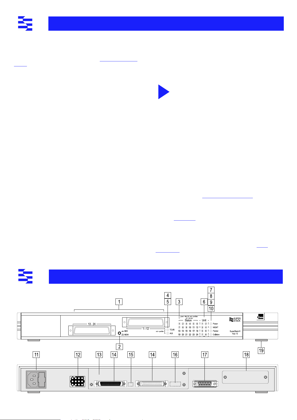
Numbered elements in this diagram refer to numbered sections in the text.
The numbers, in bold, are used as references in the text.
USE
THE
H
UB
10
Page 4

iii
i
1
“
2
3
4
5
6
7
8
. 9
10
In
Front Panel
24 Telco Ports
A range of Telco connectors can be used with the Hub 10 Telco. Refer to
Introduction ” for more information.
CAUTION: Do not over-tighten the screws on the Telco
connectors.
MDI Switch
The Media Dependent Interface (MDI) switch controls the operation of
port 24. The switch is recessed and can be operated using a ball-point
pen or similar instrument.
Out In this position you can connect port 24 to a
MDIX
MDI
To form an inter-repeater link using two Hub 10 Telcos, connect port 24
on unit 1 to any port on unit 2. Ensure that the MDI switch on unit 1 is
IN (MDI) and that if port 24 is used on unit 2, the MDI switch is OUT
(MDIX).
STATUS LEDs
The STATUS LEDs show the partition state of a port and whether or not
the Link Pulse signal is present on the segment connected to a port
Green The Link Pulse signal is being received and the segment
attached to the port is functional. If the port does not
transmit/receive, check the Disable On Boot switch, 15, is
Enabled.
Red The Link Pulse signal is being received and the port is
partitioned from the network.
■
■
■
■
If the cause of the partition is found and corrected, the segment
is reconnected automatically, after the first valid packet is
transmitted to, or received from the segment.
Off The Link Pulse signal is not being received.
■
■
■
■
■
■
If these checks do not identify the cause of a problem, it may be that the
Hub 10 Telco or the device connected to the port is faulty. Contact your
supplier for further advice.
TCVR LED
The TCVR LED lights red if the Transceiver Module port has partitioned.
Refer to “ STATUS LEDs ” , 3 , for information on what to do if a segment is
partitioned.
A transceiver module port connected to coaxial cable segment
may partition if the segment is incorrectly terminated.
workstation or any other DTE.
In this position you can connect port 24 to any
internal cross-over (X) port on another 10Base-T
repeater using normal twisted pair cable to form an
inter-repeater link.
Check the connections and the cable for any breaks in the
segment.
Make sure the transceiver attached to the DTE is correctly
connected and powered up.
Check for illegal 802.3 configurations, in particular, loops.
Check that the Disable On Boot switch, 15 , is set for units
with standby ports in resilient links.
Check that the attached DTE is switched on.
Check that the Link Pulse signal has not been disabled by
management software.
Check that the attached transceiver is not faulty.
If it is an inter-repeater link, check the setting of the MDI
switch.
Carry out the checks recommended for when a STATUS LED
is red.
Check for no more than 4 repeater stacks in series, and that
cable lengths do not exceed the maximum specified in the
standard for that medium.
The Transceiver Module port may partition if the SQE test pulse is
enabled on its transceiver. SQE test should be disabled on transceivers
used to connect 802.3 repeaters to the network.
AUI LED
The AUI LED lights red if the AUI port has partitioned. Refer to “ STATUS
LEDs ” , 3 , for information on what to do if a segment is partitioned.
An AUI port connected to coaxial cable segment may partition
if the segment is incorrectly terminated.
The AUI port may partition if the SQE test pulse is enabled on its
transceiver. SQE test should be disabled on transceivers used to connect
802.3 repeaters to the network.
UNIT LEDs
The UNIT LEDs indicate the position of this unit in the stack, providing a
Management Module or Advanced RMON Module has been fitted to a
unit in the stack. The appropriate UNIT LED will light green; if this unit
has a Management Module (or Advanced RMON Module) fitted, it will
show as unit number 1. If the unit is in a stack which does not contain a
Management Module or Advanced RMON Module, the UNIT LEDs will
not light.
Power LED
The Power LED lights green to indicate the power supply to the unit is
correct. If it is not lit, and:
None of the ports work
The AUI and Transceiver
Module ports do not work,
but the twisted pair ports
work
All ports function normally The LED has failed. Contact your supplier.
Check the fuse in the IEC socket and the
fuse within the power cable's plug (if
fitted).
The internal fixed fuse for the power
supply to the AUI and Transceiver
Module ports has blown. Contact your
supplier.
MGMT LED
The MGMT LED indicates the status of the Management Module or
Advanced RMON Module if fitted.
Off
Green/(Yellow) The Management Module (or Advanced RMON
Green flashing Management agent software is being downloaded.
Red
There is no Management Module or Advanced RMON
Module fitted to the Hub 10 Telco or the internal
connection to it has been broken.
Module) is fitted and functioning normally.
There is a fault on the Management Module (or
Advanced RMON Module) or one of the units in the
stack. Check all connections and refer to the
Management Module guide for more information.
Packet LED
The Packet LED flashes yellow whenever a packet is received on one of
the 12 twisted pair ports, the AUI port, or the Transceiver Module port.
If this LED does not flash, there are no packets being received by the
unit.
Collision LED
The Collision LED flashes yellow when a packet collision has been
detected on a segment connected to one of the 24 Telco ports, the AUI
port, or the Transceiver Module port.
Under normal 802.3 operation, collisions occur and cause the Collision
LED to flash. The probability of collisions increases during heavy activity
on the network. The Auto Partition/Reconnection function partitions a
segment from the rest of the network if more than 64 consecutive
collisions are detected on that segment.
Page 5

11
12
13
14
15
16
17
18
19
Rear Panel Connection
Power Supply and Fuse
Correct fuse location
L’emplacement du fusible correct
Richtige Stellung der Sicherung
Hub Expansion Connectors
You can connect units together in a stack to form a single logical
repeater. You need one Hub Expansion Cable (3C625) for each additional
unit in the stack. The diagram below shows how you connect units
together. Do not use two cables to connect any two units to each other
- they will not work if you do this.
Spare fuse location - DO NOT USE
L’emplacement du fusible incorrect - NE PAS UTILISER
Falsche Stellung der Sicherung - NICHT VERWENDEN
WARNING : Ensure that the power supply is disconnected before
opening the fuse holder cover.
The Hub 10 Telco automatically adjusts to the supply voltage.
The fuse is suitable for both 110V A.C. and 220-240V A.C.
operation.
To change the fuse, release the fuse holder by gently levering a
small screwdriver under the fuse holder catch. Only 2A
anti-surge type fuses of the same type and manufacture as the
original should be used with the Hub 10 Telco. Close the fuse
holder.
AVERTISSEMENT:
avant d'ouvrir le couvercle du contenant du fusible.
L'unité s'ajuste automatiquement à la tension d'alimentation.
Le fusible est convenable aux deux opérations 110 V C.A. et
220-240 V C.A.
Pour changer le fusible, dégager le contenant du fusible en
mettant doucement un petit tournevis sous l'arrêt de
contenant du fusible. Seulement les fusibles de types 2A
anti-transitoires du même type et fabricant que l'original
doivent être utilisés.
WARNUNG:
vom Netzstrom trennen.
Das Gerät stellt sich automatisch auf die
Versorgungsspannung ein. Die Sicherung ist sowohl für 110V
A.C. wie für 220-240V A.C. geeignet.
Zum Auswechseln der Sicherung durch leichtes Heben mit
einem kleinen Schraubenzieher die Abdeckungsklappe der
Sicherungshalterung lösen. Sicherungen nur durch gleichen
Typ und Wert wie die Originalsicherung ersetzen. Sicherung
auswechseln und die Klappe der Sicherungshalterung wieder
schließen.
Assurer que l'alimentation soit débranchée
Vor dem Öffnen der Sicherungshalterung das Gerät
Socket for Redundant Power System
Only connect a 3Com Redundant Power System, option 3C565047, to
this socket. For details, follow the installation instructions in the guide
accompanying the Redundant Power System.
Management Module or Advanced RMON Module Slot
The Hub 10 Telco can be fitted with an optional SuperStack II Hub 10
Management Module or Advanced RMON Module. When the module
has an IP/IPX address, you can then use SNMP management to manage
the stack containing the unit.
CAUTION: Do not remove the Management Module blanking
plate with the power still connected.
For instructions on installing either module in an Hub 10 unit, refer to
the guide that accompanies the module. You will need to remove the
blanking plate to reveal the slot for the module.
If you subsequently remove the Management or Advanced RMON
Module from the Hub 10 unit, you must replace the blanking plate to aid
the circulation of cooling air and prevent the entry of dust and debris.
Disconnect power from all units that will form part of the new
stack. Connect the male hub expansion connector of one unit to the
female hub expansion connector of the next unit. Repeat this process
until all the units are connected together. Refer to “ Stacking Units ” for
the number of units allowed in a stack.
CAUTION: If you intend to rack or wall mount the units,
connect the units after they have been mounted.
Disable On Boot Switch
This switch is located behind the blanking plate covering the
Management Module slot, 13 . The unit is shipped with this switch set to
Enable.
CAUTION: Do not disable ports unless you have a
management module installed in the stack.
Enable TP ports on front panel are enabled on power up. They
may be subsequently disabled via management software.
Disable TP ports on front panel are disabled on power up until
management software enables them. This is required for
standby ports in resilient links.
Management / Advanced RMON Module Power Cable
Connector
This plug, located behind the blanking plate, provides power to an Hub
10 Management Module or Advanced RMON Module, if fitted and
connected. See the guide accompanying the module for installation
instructions.
AUI Port
You can connect the unit to any 802.3 transceiver using an AUI cable
(sometimes known as a transceiver cable or drop cable). Connect one
end of the AUI cable to the AUI port on the rear panel of the unit and
the other end to the AUI port on the transceiver. Engage the slide locks
at both ends of the AUI cable.
Ensure that SQE test is disabled.
Transceiver Module Slot
A variety of 3Com plug-in Transceiver Modules or the Bridge
MicroModule can be installed in the Hub 10 Telco (see overleaf for a list).
Transceivers provide direct network connections to different media.
CAUTION: Do not remove the Transceiver Module blanking
plate with the power still connected.
Ensure that SQE test is disabled.
To install a Transceiver Module, refer to the guide that accompanies it. If
you subsequently remove the Transceiver Module, you must replace the
blanking plate to aid the circulation of cooling air and prevent the entry
of dust and debris.
Self-adhesive Pads
The Hub 10 Telco is supplied with 4 self-adhesive rubber pads. If the unit
is to be part of a free standing stack, apply the pads to the underside of
the unit; stick a pad in the marked area at each corner of the unit. Place
the units on top of each other, ensuring that the pads of the upper unit
locate with the recesses of the lower unit.
Do not apply the pads if you intend to rack or wall mount the unit.
Page 6

i
Siting the Hub 10 Telco
CAUTION: When installing the Hub 10 Telco in a stack with
FMS units, the Hub 10 Telco must be installed beneath any FMS
units.
When deciding where to site the Hub 10 Telco ensure:
■
It is accessible and cables can be connected easily.
■
Cabling is away from:
sources of electrical noise such as radios, transmitters and
■
broadband amplifiers.
power lines and fluorescent lighting fixtures.
■
■
Water or moisture cannot enter the case of the unit.
■
Air flow around the unit and through the vents in the side of the
case is not restricted (3Com recommend that you provide a
minimum of 25mm (1 inch) clearance).
To prolong the operational life of your units:
■
Never stack units more than eight high if free standing.
■
Do not place objects on top of any unit or stack.
■
Do not obstruct any vents at the sides of the case.
Rack or Wall Mounting
The Hub 10 Telco can be mounted in a 19 inch equipment rack or else
wall-mounted using the LinkBuilder Rack Mounting Kit. See “ Rack
Mounting Kit Instructions ” overleaf.
Stacking Units
The Hub 10 Telco can be linked to other Hub 10 units to form a stack, or
can be part of a mixed stack consisting of Hub 10, FMS, FMS II, 10BT or
10BTi units.
Different rules apply on stacking units if the stack only consists of Hub
10 and/or FMS II units compared to a stack with other mixed units.
Hub 10/FMS II only stacks
Up to 8 Hub 10 (FMS II) units can be linked together to form a free
standing stack or be mounted in a 19 inch rack, in a managed or
unmanaged configuration.
Only fit a Hub 10 or LinkBuilder FMS II Management Module or
Advanced RMON Module, to either the unit at the top or bottom of the
stack.
Mixed stacks of Hub 10/FMS II/FMS/10BT/10BTi
Link up to 8 units in a free standing stack or mounted in a rack. But any
FMS, 10BT or 10BTi units must be units 1-4 in a managed stack.
If mixing Hub 10 (FMS II) and FMS units in a free standing stack, the
narrower FMS units must be positioned at the top of the stack. This
restriction does not apply if rack mounting the units.
Stack Management
To manage any stack containing a Hub 10 unit, the Management
Module must have the correct version of the agent installed. The table
below details the minimum agent version numbers for each
management module.
3C16030 LinkBuilder FMS Management Module
3C16630 LinkBuilder FMS II Management Module
3C16630A SuperStack II (FMS II) Management Module 3.14
3C16632 SuperStack II (FMS II) Advanced RMON Module 1.01
Check which version you have installed before adding a Hub 10 unit to
your stack.
If you need to upgrade your agent, and a disk containing the new
versions is not included in the packaging, a free upgrade is available
from the 3Com bulletin boards (see “ Products and Bulletin Boards ” ). The
upgrade includes instructions on how to load the agent.
3.04
3.04
Managing with an FMS Management Module
rack mounted stacks: the module must be fitted to an FMS unit at
the top or bottom of the stack.
free standing stacks: the module must be fitted to an FMS unit at
the top of the stack.
Managing with a Hub 10 (FMS II) Management
Module (3C16630A) or Advanced RMON Module
(3C16632)
rack mounted stacks: the module must be fitted to a Hub 10 (FMS II)
unit at the top or bottom of the stack.
free standing stacks: the module must be fitted to a Hub 10 (FMS II)
unit at the bottom of the stack.
If you have a Hub 10, LinkBuilder FMS or FMS II unit fitted with a
Management Module, and a LinkBuilder 10BTi in your stack, the Hub 10,
FMS or FMSII Management Module will manage the stack.
The LinkBuilder 10BTi can only manage LinkBuilder 10BT units
and the FMS Telco Hub (3C16271). 10BTi cannot manage other
FMS units or any Hub 10 (FMS II) units.
Power Up
Use the following sequence to power up the Hub 10 Telco:
■
Check the Disable On Boot switch at the rear and select position
as appropriate: see 15 .
■
Check the network connections and cables.
■
Check the hub expansion cables if in a stack.
■
Connect the power supply cable to the appropriate power socket
on the rear panel of the unit, see 11 or 12 .
■
Connect the plug to the power supply outlet socket and switch
on the power supply at the socket. If you are using a 3Com
Redundant Power Supply make sure it is switched on.
When the Hub 10 Telco is powered up, the Power LED should be lit. If it
is not, refer to “ Power LED ” , 9 .
Spot Checks
At frequent intervals you should visually check the Hub10 Telco. Regular
checks can give you an early warning of a possible failure; any problems
can then be attended to when there will be least effect on users. Check
the following:
Cabling
Cooling fans
Transceiver Module Check that the Transceiver Module is connected
Check that all external cabling connections are
secure and that no cables are pulled taut.
Check that the cooling fans are operating and are
not obstructed. The fans are fitted to the right
hand side of the unit when viewed from the front.
securely. Refer to the guide provided with the
Transceiver Module.
What To Do Next?
If the Hub 10 Telco fails to operate successfully, contact your supplier
with the following information before returning the unit:
■
product number
■
serial number
■
a brief description of the fault
When returning any equipment to your supplier make sure the
equipment is packed suitably for transit.
Page 7

P
RODUCTS AND BULLETIN BOARDS
Products
SuperStack II Hub 10 is part of the SuperStack II range of 3Com
products. Contact your supplier for the latest product information.
Hub 10 hubs
3C16670A SuperStack II Hub 10 12Port TP
3C16671A SuperStack II Hub 10 24Port TP
3C16672A SuperStack II Hub 10 24Port Telco
3C16665A SuperStack II Hub 10 6Port ST Fiber Optic
Hub 10 management
3C16630A SuperStack II Hub10 Management Module
3C16632 SuperStack II Hub10 Advanced RMON Module
Transceiver Modules
3C12060 Female AUI
3C12063 TP
3C12064 Fan Out (male AUI)
3C16060 Bridge MicroModule
R
ACK
Introduction
The Hub 10 Telco is supplied with two mounting brackets and four
screws. These are used for rack mounting and wall mounting the unit.
When mounting the unit, you should take note of the guidelines given
in the section “ Siting the Hub 10 Telco ” overleaf.
Wall Mounting Hub 10 Units
CAUTION: Disconnect all cables from the Hub 10 unit(s) before
continuing. Remove the self-adhesive pads from underside of
the unit(s), if already fitted.
Fitting the brackets to wall mount one unit
■
Place the Hub 10 unit the right way up on a hard, flat surface with
the front facing towards you.
■
Locate a mounting bracket over the mounting holes on one side
of the unit, as shown in figure 1 below.
■
Insert the two screws and fully tighten with a screwdriver.
Repeat the last two steps for the other side of the Hub 10 unit.
Fitting the brackets to wall mount two units
■
Stack the Hub 10 units the right way up on a hard, flat surface
with the front facing towards you.
■
Locate two mounting brackets over the mounting holes on one
side of the units, as shown in figure 2 below.
■
Insert the three screws and fully tighten with a screwdriver.
Repeat the last two steps for the other side of the units.
3C12065 Fiber Optic (ST)
3C12066 Coaxial
3C12067 FB
M
OUNTING KIT INSTRUCTIONS
Bulletin Boards
Management agent software upgrades are available from these 3Com
bulletin boards:
Australia (61) (2) 9955 2073
France
Germany (49) (89) 627 32 188
Hong Kong (852) 2537 5608
Italy
3Com Corporation
P.O. Box 58145
5400 Bayfront Plaza
Santa Clara
CA 95052-8145
USA
To wall mount the Hub 10 unit(s):
Ensure that the wall you are going to use is smooth, flat, dry and sturdy.
Attach a piece of plywood (12" x 20" x 0.5") securely to the wall if
necessary, and mount the Hub 10 unit(s) as follows:
■
■
Reconnect all cables.
(33) (1) 69 86 69 54 Singapore (65) 534 5693
or 627 32 189
(39) (2) 273 00680
(fee required)
Position the unit(s) against the wall (or plywood) ensuring that
the ventilation holes face sideways. Mark on the wall the position
of the screws holes for both wall brackets. Drill the four holes.
Using suitable fixings and screws (not provided), attach the unit(s)
securely to the wall (or plywood).
Rack Mounting Hub 10 Units
The Hub 10 Telco is 1U high and will fit a standard 19inch rack.
CAUTION: Disconnect all cables from the Hub 10 unit before
continuing. Remove the self-adhesive pads from underside of
unit, if already fitted.
■
Place the unit the right way up on a hard, flat surface with the
front facing towards you.
■
Locate a mounting bracket over the mounting holes on one side
of the unit, as shown in figure 3 below.
■
Insert the two screws and fully tighten with a suitable screwdriver.
■
Repeat the two previous steps for the other side of the unit.
■
Insert the unit into the 19" rack and secure with suitable screws
(not provided).
Reconnect all cables.
Japan
Ta iwa n
U.K.
U.S.
c/o 3Com Centre
Boundary Way
Maylands Park South
Hemel Hempstead
Herts HP2 7YU
UK
(81) (3) 3345 7266
(886) (2) 377 5838
(44) (1442) 438278
(1) (408) 980 8204
Page 8

L
IMITED
For first five years - +5 Lifetime Limited Warranty
The SuperStack II Hub 10 Fiber benefits from 3Com’s enhanced +5 Lifetime Limited
Warranty. This provides a full 5 years of advanced hardware exchange from your date of
purchase in accordance with 3Com’s standard terms and conditions. To qualify, you must
submit your warranty registration card to 3Com. After the initial 5 year period, the
warranty reverts to 3Com’s standard lifetime limited warranty. The +5 Lifetime Limited
Warranty is not offered or is void where restricted or prohibited by law.
After first five years - Lifetime Limited Warranty
The duration of the 3Com standard lifetime limited warranty i s lifetime, excluding the
power supply and fans. See below for terms and conditions of this warranty.
Hardware:
3Com warrants its hardware products to be free from defects in workmanship
and materials, under normal use and service, for the following lengths of time from the
date of purchase from 3Com or its Authorized Reseller:
Network adapters
Other Hardware products One year (unless otherwise specified above)
Spare parts and spare kits 90 days
If a product does not operate as warranted above during the applicable warranty period,
3Com shall, at its option and expense, repair the defective product or part, deliver to
Customer an equivalent product or par t to replace the defec tive item, or refund to
Customer the purchase price paid for the defective product. All products that are
replaced will become the propert y of 3Com. Replacement products may be new or
reconditioned. Any replaced or repaired product or part has a ninety (90) day warranty or
the remainder of the initial warranty period, whichever is longer.
3Com shall not be responsible for any software, firmware, information, or memory data
of Customer contained in, stored on, or integrated with any products returned to 3Com
for repair, whether under warranty or not.
Software:
3Com warrants that the software programs licensed from it will perform in
substantial conformance to the program specifications therefor for a period of ninety
(90) days from the date of purchase from 3Com or its Authorized Reseller. 3Com warrants
the media containing software against failure during the warranty period. No updates
are provided. 3Com's sole obligation with respect to this express warranty shall be (at
3Com's discretion) to refund the purchase price paid by Customer for any defective
software products, or to replace any defective media with software which substantially
conforms to 3Com's applicable published specifications. Customer assumes responsibility
for the selection of the appropriate applications program and associated reference
materials. 3Com makes no warranty or representation that its software products will
work in combination with any hardware or applications software products provided by
third partie s, that the operation of the software produc ts will be uninter rupted or error
free, or that all defects in the software products will be corrected. For any third party
products listed in the 3Com software product documentation or specifications as being
compatible, 3Com will make reasonable efforts to provide compatibility, except where
the non-compatibility is caused by a "bug" or defect in the third party's product.
Standard Warranty Service:
obtained by delivering the defective product, accompanied by a copy of the dated proof
of purchase, to 3Com's Corporate Service Center or to an Authorized 3Com Service
Lifetime
Standard warranty service for hardware products may be
W
ARRANTY
Center during the applicable warranty period. Standard warranty service for software
products may be obtained by telephoning 3Com's Corporate Service Center or an
Authorized 3Com Service Center, within the warranty period. Products returned to
3Com's Corporate Service Center must be pre-authorized by 3Com with a Return
Material Authorization (RMA) number marked on the outside of the package, and sent
prepaid, insured, and packaged appropriately for safe shipment. The repaired or replaced
item will be shipped to Customer, at 3Com's expense, not later than thirty (30) days after
receipt of the defective product by 3Com.
Warranties Exclusive:
ABOVE, CUSTOMER'S SOLE REMEDY FOR BREACH OF THAT WARRANTY SHALL BE REPAIR,
REPLACEMENT, OR REFUND OF THE PURCHASE PRICE PAID, AT 3COM'S OPTION. TO THE
FULL EXTENT ALLOWED BY LAW, THE FOREGOING WARRANTIES AND REMEDIES ARE
EXCLUSIVE AND ARE IN LIEU OF ALL OTHER WARRANTIES, TERMS, OR CONDITIONS,
EXPRESS OR IMPLIED, EITHER IN FACT OR BY OPERATION OF LAW, STATUTORY OR
OTHERWISE, INCLUDING WARRANTIES, TERMS, OR CONDITIONS OF MERCHANTABILIT Y,
FITNESS FOR A PARTICULAR PURPOSE, AND SATISFACTORY QUALITY. 3COM NEITHER
ASSUMES NOR AUTHORIZES ANY OTHER PERSON TO ASSUME FOR IT ANY OTHER
LIABILITY IN CONNECTION WITH THE SALE, INSTALLATION, MAINTENANCE OR USE OF ITS
PRODUCTS.
3COM SHALL NOT BE LIABLE UNDER THIS WARRANTY IF ITS TESTING AND EXAMINATION
DISCLOSE THAT THE ALLEGED DEFECT IN THE PRODUCT DOES NOT EXIST OR WAS
CAUSED BY CUSTOMER'S OR ANY THIRD PERSON'S MISUSE, NEGLECT, IMPROPER
INSTALLATION OR TESTING, UNAUTHORIZED ATTEMPTS TO REPAIR OR MODIFY, OR ANY
OTHER CAUSE BEYOND THE RANGE OF THE INTENDED USE, OR BY ACCIDENT, FIRE,
LIGHTNING, OR OTHER HAZARD.
Limitation of Liability:
FOR ITSELF AND ITS SUPPLIERS ANY LIABILITY, WHETHER BASED IN CONTRACT OR TORT
(INCLUDING NEGLIGENCE), FOR INCIDENTAL, CONSEQUENTIAL, INDIRECT, SPECIAL, OR
PUNITIVE DAMAGES OF ANY KIND, OR FOR LOSS OF REVENUE OR PROFITS, LOSS OF
BUSINESS, LOSS OF INFORMATION OR DATA, OR OTHER FINANCIAL LOSS ARISING OUT OF
OR IN CONNECTION WITH THE SALE, INSTALLATION, MAINTENANCE, USE, PERFORMANCE,
FAILURE, OR INTERRUPTION OF ITS PRODUCTS, EVEN IF 3COM OR ITS AUTHORIZED
RESELLER HAS BEEN ADVISED OF THE POSSIBILITY OF SUCH DAMAGES, AND LIMITS ITS
LIABILITY TO REPAIR, REPLACEMENT, OR REFUND OF THE PURCHASE PRICE PAID, AT
3COM'S OPTION. THIS DISCLAIMER OF LIABILITY FOR DAMAGES WILL NOT BE AFFECTED
IF ANY REMEDY PROVIDED HEREIN SHALL FAIL OF ITS ESSENTIAL PURPOSE.
Some countries, states, or provinces do not allow the exclusion or limitation of implied
warranties or the limitation of incide ntal or conse quential damages for certain products
supplied to consumers or the limitation of liability for personal injury, so the above
limitations and exclusions may be limited in their application to you. This warranty gives
you specific legal rights w hich may vary depending on local law.
Governing Law:
California.
3Com Corporation
Tel: (408) 764-5000 9/1/96
IF A 3COM PRODUCT DOES NOT OPERATE AS WARRANTED
TO THE FULL EXTENT ALLOWED BY LAW 3COM ALSO EXCLUDES
This Limited Warranty shall be governed by the laws of the state of
, 5400 Bayfront Plaza, Santa Clara, CA, 95052-8145, U.S.A.
E
LECTRO-MAGNETIC COMPATABILITY
FCC Statement
This equipment has been tested and found to comply with the limits for a class A digital
device, pursuant to part 15 of FCC Rules. These limits are designed to provide reasonable
protection against interference when the equipment is operated in a commercial
environment. This equipment generates, uses and can radiate radio frequency energy
and, if not installed and used in accordance with the instruction manual, may cause
harmful interference with radio communications. Operation of this equipment in a
residential area is likely to cause harmful interference in which case the user will be
required to correct the interference at his own expense.
L
EGAL
3Com Corporation 5400 Bayfront Plaza Santa Clara, California 95052-8145
© 3Com Ireland, May 1996. All rights reserved. No part of this documentation may be
reproduced in any form or by any means or used to make any derivative work (such as
translation, transformation, or adaptation) without permission from 3Com Ireland.
3Com Ireland reserves the right to revise this documentation and to make changes in
content from time to time without obligation on the part of 3Com Ireland to provide
notification of such revision or change.
3Com Ireland provides this documentation without warranty of any kind, either implied
or expressed, including, but not limite d to, the implied warranti es of merchantability a nd
fitness for a particular purpose. 3Com may make improvements or changes in the
product(s) and/or the program(s) described in this documentation at any time.
UNITED STATES GOVERNMENT LEGENDS:
If you are a Unite d States government agency, then this documentation and the
software described herein are provided to you subject to the following restricted rights:
For units of the Department of Defense:
Restricted Rights Legend: Use, duplication or disclosure by the Government is subject to
restrictions as set forth in subparagraph (c) (1) (ii) for restricted Rights in Technical Data
and Computer Software clause at 48 C.F.R. 52.227-7013. 3Com Ireland, c/o 3Com Centre,
Boundary Way, Maylands Park South, Hemel Hempstead, Hertfordshire, HP2 7YU, UK.
N
OTICES
CSA Statement
This Class A digital apparatus me ets all requireme nts of the Canadian
interference-Causing Equipment Regulations.
Cet appareil numérique de la classe A respecte toutes les exigences du Règlement sur le
matériel brouilleur du Canada.
For civilian agencies:
Restricted Rights Legend : Use, reproduction or disclosure is subject to restrictions as set
forth in subparagraph (a) through (d) of the Commercial Computer Software - Restricted
Rights Clause at 48 C.F.R. 52.227-19 and the limitations set forth in 3Com Corporation's
standard commercial agreement for the software. Unpublished rights reserved under the
copyright laws of the United States.
Unless ot herwise indicated, registered trademarks are registered in the United States and
may or may not be registered in other countries.
3Com and LinkBuilder are registered trademarks of 3Com Corporation. SuperStack II and
FMS are trademarks of 3Com Corporation. Other brand and product names may be
registered trademarks or trademarks of their respective holders.
The technology behind 3Com's LAN Security Architecture is protected by U.S. patents
5,161,192 and 5,386,470 (foreign patents applied for).
Part Number: DUA1667-2AAA03
Revision: 01
Published: December 1996
 Loading...