

Page 1

NBX® Administrator’s Guide
Release 4.2
■ SuperStack 3 NBX
■ NBX 100
http://www.3com.com/
Part Number 900-0130-01 Rev AA
Published: October 2003
Page 2

3Com Corporation
350 Campus Drive
Marlborough, MA
01752-3064
Copyright © 2003, 3Com Corporation. All rights reserved. No part of this documentation may be reproduced
in any form or by any means or used to make any derivative work (such as translation, transformation, or
adaptation) without written permission from 3Com Corporation.
3Com Corporation reserves the right to revise this documentation and to make changes in content from time
to time without obligation on the part of 3Com Corporation to provide notification of such revision or change.
3Com Corporation provides this documentation without warranty, term, or condition of any kind, either
implied or expressed, including, but not limited to, the implied warranties, terms, or conditions of
merchantability, satisfactory quality, and fitness for a particular purpose. 3Com may make improvements or
changes in the product(s) and/or the program(s) described in this documentation at any time.
If there is any software on removable media described in this documentation, it is furnished under a license
agreement included with the product as a separate document, in the hardcopy documentation, or on the
removable media in a directory file named LICENSE.TXT or !LICENSE.TXT. If you are unable to locate a copy,
please contact 3Com and a copy will be provided to you.
UNITED STATES GOVERNMENT LEGEND
If you are a United States government agency, then this documentation and the software described herein are
provided to you subject to the following:
All technical data and computer software are commercial in nature and developed solely at private expense.
Software is delivered as “Commercial Computer Software” as defined in DFARS 252.227-7014 (June 1995) or
as a “commercial item” as defined in FAR 2.101(a) and as such is provided with only such rights as are
provided in 3Com’s standard commercial license for the Software. Technical data is provided with limited rights
only as provided in DFAR 252.227-7015 (Nov 1995) or FAR 52.227-14 (June 1987), whichever is applicable.
You agree not to remove or deface any portion of any legend provided on any licensed program or
documentation contained in, or delivered to you in conjunction with, this guide.
Unless otherwise indicated, 3Com registered trademarks are registered in the United States and may or may
not be registered in other countries.
3Com, NBX, the 3Com logo, and SuperStack are registered trademarks of 3Com Corporation. NBX NetSet and
pcXset are trademarks of 3Com Corporation.
Adobe is a trademark and Adobe Acrobat is a registered trademark of Adobe Systems Incorporated.
InstallShield is a registered trademark of InstallShield Software Corporation. 5ESS is a registered trademark and
4ESS is a trademark of Lucent Technologies. Microsoft, Windows, Windows 2000, and Windows NT are
registered trademarks of Microsoft Corporation.
All other company and product names may be trademarks of the respective companies with which they are
associated.
Page 3

CONTENTS
ABOUT THIS GUIDE
How to Use This Guide 15
Conventions 16
International Terminology 16
Your Comments 17
1 INTRODUCTION
Network-based Telephony 19
Overview of the System Software 20
Auto Attendant 20
Auto Discovery and Auto Relocation 20
Virtual Tie Lines 20
Integrated Voice Mail and Messaging Features 20
Redialing From Call Logs 21
Call Recording 21
NBX NetSet Administration Utility 22
NBX NetSet Features 23
2 DIAL PLAN
Dial Plan Concepts and Overview 28
Call Process Flow 29
Inbound and Outbound Call Processing 29
NBX System Database 30
NBX System Dial Plan 30
Pretranslation 31
Page 4

Routing 31
System Features Affected by the Dial Plan Configuration 32
Dial Plan Tables 34
Dial Plan Command Format 34
Internal Dial Plan Table 38
Incoming Dial Plan Table 38
Least Cost Routing Dial Plan Table 39
Adding New Dial Plan Tables 40
Dial Plan Pretranslators 40
Pretranslators for Incoming Calls 41
Pretranslators for Certain Outgoing Calls 42
Managing the Dial Plan Configuration File 44
Accessing the Dial Plan 44
Creating Dial Plan Configuration Files 44
Importing and Exporting Dial Plan Configuration Files 45
Importing a User-Defined Dial Plan 47
Exporting (Saving) a Dial Plan Configuration File 48
Testing a Dial Plan 49
Generating a Dial Plan Report 50
Modifying a Dial Plan Configuration File 51
Outdialing Prefix Settings 52
Managing Extensions 52
Extension Settings Overview 52
Changing Extension Length and Ranges 56
How Auto Discovery Assigns Extensions 56
Modifying Extensions 57
Managing Extension Lists 58
Adding an Extension List 60
Modifying an Extension List 61
Removing an Extension List 62
Managing Dial Plan Tables 62
Determining Which Devices Use Dial Plan Tables 63
Removing a Dial Plan Table 64
Managing Dial Plan Pretranslators 64
Identifying Devices Using Pretranslators 64
Identifying Devices Using Pretranslators for CLI 65
Removing a Pretranslator from the Dial Plan 65
Configuring the Dial Plan for the 4ESS Protocol (T1) 66
Page 5

Overview of Voice Profile for Internet Mail 67
Configuring the Dial Plan for VPIM 68
Configuring VPIM Parameters Using NBX NetSet 71
VPIM Control Parameters 71
Operations Management 71
Statistics 73
Advanced Settings 74
Configuring Domain Name Server Information 77
Overview of Virtual Tie Lines 77
VTL Connections Using Unique Extension Ranges 78
VTL Connections Using Site Codes 79
Conference Calls 80
How to Configure a Virtual Tie Line 81
License Installation 81
Dial Plan Configuration 82
Updating the Extension List 85
Adding VTL Devices to the Pretranslators (Optional) 86
Verification of the Virtual Tie Line 87
Call Rerouting for Virtual Tie Lines 90
Example Dial Plan Entries 90
Managing Existing Virtual Tie Lines 92
Modifying a Virtual Tie Line Name 92
Viewing and Resetting Virtual Tie Line Statistics 93
Enabling Audio Compression 94
Enabling System-wide Silence Suppression 94
Using a VTL Password 95
Configuring a VTL Password 95
Configuring VTL Passwords in the Dial Plan 96
Toll Calls Without a VTL Password 99
Music On Hold 99
Troubleshooting VTL Calls 99
Dial Plan Configuration File Commands 100
Dial Plan Command Summary 100
List of Dial Plan Commands 103
Sample Solutions Using Dial Plan Configuration File Commands 116
Page 6

3 DEVICE CONFIGURATION
Adding, Removing, and Modifying Telephones 126
Adding a New Telephone 126
Modifying a Telephone 131
Checking a Telephone’s Status 131
Removing a Telephone 133
Rebooting a Telephone 133
Adding a Remote Telephone 134
Remote NAPT Device Configuration 134
Creating and Managing Bridged Extensions 135
Example Bridged Extensions Configurations 137
Defining Bridged Extensions 138
Defining Bridged Extensions on a Primary Telephone 138
Defining Bridged Extensions on a Secondary Telephone 139
Modifying Bridged Extensions 140
Sample Calling Situations Using Bridged Extensions 140
Viewing Bridged Extension Information 142
Creating and Managing Telephone Groups 143
Creating a New Telephone Group 143
Modifying a Telephone Group 143
Removing a Telephone Group 144
Viewing Telephone Group Membership 144
Recording and Monitoring Telephone Calls 144
Recording Calls Between Telephones with Different Recording Settings
145
Remote Telephones 146
Music On Hold 146
Non-NBX Telephones 146
Creating and Managing Button Mappings 147
Mapping Access Buttons 147
Mappings for Users and Groups 148
Creating a Busy Lamp/Speed Dial Button Mapping 148
Creating a Delayed Ringing Pattern 149
Creating Groups and Button Mappings 150
Changing Device IP Settings 161
Configuring Call Park 162
Adding a Call Park Extension 162
Page 7

Changing the Name of a Call Park Extension 163
Removing a Call Park Extension 163
Configuring the NBX 1105 Attendant Console 163
Adding an Attendant Console 164
Modifying an Attendant Console 165
Viewing Attendant Console Status 165
Removing an Attendant Console 167
Configuring Attendant Console Buttons 167
Changing Attendant Console IP Settings 186
Configuring and Managing Analog Line Card Ports 186
Configuring a Line Card Port 187
Modifying a Line Card Port 191
Removing a Line Card Port 192
Verifying Line Card Port Status 192
Rebooting a Line Card Port 194
Advanced Settings 195
Connecting and Managing Analog Devices 199
Adding an Analog Terminal Card 199
Adding an Analog Terminal Adapter (ATA) 201
Modifying an Analog Terminal Port 203
Removing an Analog Terminal Adapter 205
Viewing The Status of an Analog Terminal Adapter 206
Advanced Settings 207
Configuring and Managing BRI-ST Digital Line Cards 213
Adding an ISDN BRI-ST Digital Line Card 213
Configuring the BRI-ST Digital Line Card 216
BRI-ST Card Status Lights 218
Modifying a BRI-ST Card 219
Adding or Modifying a BRI Group 220
Modifying BRI Card Channels 223
Modifying IP Settings for a BRI Card 225
Removing a BRI Digital Line Card 225
Configuring and Managing E1 Digital Line Cards 226
Adding an E1 Digital Line Card 227
Configuring the E1 Digital Line Card 229
E1 Card Status Lights 231
Modifying an E1 Card 231
Adding or Modifying an E1 Group 234
Modifying E1 Card Channels 237
Page 8

Modifying IP Settings for an E1 Card 239
Removing an E1 Digital Line Card 240
Configuring and Managing T1 Digital Line Cards 240
Adding a T1 Digital Line Card 241
Configuring a T1 Digital Line Card for the DS1 Protocol 244
Configuring a T1 Digital Line Card for ISDN PRI Signaling 248
T1 Card Status Lights 252
Modifying a T1 Card 252
Support of AT&T’s 4ESS Switch Protocol 254
Modifying a T1 Group 257
Modifying T1 Card Channels 259
Modifying IP Settings for a T1 Card 261
Removing a T1 Digital Line Card 261
4 USER CONFIGURATION
Users 263
Phantom Mailboxes 263
Call Pickup 264
Group Numbers 264
TAPI Route Points 265
Redirect Behaviors 265
TAPI Route Point Capacities 267
Creating a TAPI Route Point 267
Modifying a TAPI Route Point 268
Viewing TAPI Route Point Statistics 269
Specifying TAPI Line Redirect Timeout 270
Hunt Groups 271
Hunt Group Considerations 271
Linear and Circular Hunt Groups 272
Calling Groups 272
Call Coverage 273
Class of Service (CoS) 273
Page 9

5 SYSTEM CONFIGURATION
System Settings 275
System-wide Settings 277
Audio Settings 280
Regional Settings 282
Date and Time 283
Timers 283
Ringing Patterns 284
Multicast Addresses 285
IP Addresses 286
Maintenance Alerts 286
Speed Dials 287
Business Identity 288
Business Information 288
Business Hours 288
System Mode 288
Security 289
TAPI Settings 289
Disk Mirroring 290
Adding a Mirror Disk 290
Verifying a Failed Disk Drive 292
Reverting to a Single-Disk System 293
6 NBX MESSAGING
NBX Voice Mail 295
Voice Mail Extensions 298
Voice Mail Passwords 298
IMAP for Integrated Voice Mail 298
Off-Site Notification 300
Status 301
Port Usage 302
User Usage 306
Auto Attendant 307
Page 10

Overview of Auto Attendant Features 307
Adding an Auto Attendant 308
Managing Auto Attendants 319
Voice Application Setup Utility 321
Testing the Auto Attendant 322
Voice Profile for Internet Mail 323
Control Parameters 324
Operations Management 324
Statistics 326
Advanced Settings 327
7 OPERATIONS
Software Upgrade 331
System Software Licensing 332
Restricted Operation 333
Considerations 334
Customer Service 335
Reboot/Shutdown 335
Manage Data 335
Backup 336
Restore 338
Convert Database 339
Purge Database 339
Purge Database and CDR 339
Purge All Voice Mail 339
Event Log 339
Licenses 340
Add a License 340
Remove a License 341
Usage Report 341
Backing Up Licenses 341
Restoring Backed-Up Licenses 341
Obtaining Details of License History 342
Regional Software 342
Install 342
Remove 343
Page 11

Details 343
Third-Party Drivers 344
NBX Software Upgrades 344
Third-Party Telephone Groups 344
8 REPORTS
Directory 345
Device List 346
System Data 346
Disk Status 346
Power Supply Status 346
Call Reporting 347
Windows Environment Specifications 347
Installing Call Reports 347
Configuring Call Reporting 348
Purge CDR 348
9 DOWNLOADS
Software 349
Additional Applications 349
Label Makers 350
Quick Reference Guides 350
10 TROUBLESHOOTING
Overview 351
Telephone Troubleshooting 352
Using the Telephone Local User Interface (LUI) Utility 352
Using H3PingIP 359
System-level Troubleshooting 360
Digital Line Card Troubleshooting 363
Alarm Conditions (Overview) 363
Page 12

Alarm Descriptions 364
Alarms on NBX Digital Line Cards 365
Configuration and Status Reports 366
Connecting a Computer to a Serial Port 370
Servicing the Network Call Processor Battery 371
Getting Service and Support 372
A INTEGRATING THIRD-PARTY MESSAGING
Installing Software on the Third-Party Messaging Server 373
Configuring the NBX System 373
Configuring NBXTSP on the Server 375
B ISDN COMPLETION CAUSE CODES
C CONFIGURING OPTION 184 ON A WINDOWS 2000 DHCP
S
ERVER
Overview 383
Assumptions 383
Creating Option 184 383
Editing Option 184 Values 384
Activating Option 184 385
D CONNEXTIONS H.323 GATEWAY
Overview of ConneXtions 388
Installation Requirements 388
WAN Router 388
Windows-based System 389
ConneXtions Software 392
Preparing for Installation 392
Assembling System Information 392
Verifying the G.723 Converter 393
Checking Service Pack (Windows NT Only) 393
Page 13

Configuring Licenses 393
Installing ConneXtions 395
Finishing the Installation 397
Overview of H.323 398
Negotiated Connections 398
Negotiated Voice Compression 399
Standard Extensions 400
Remote Internet Device Connections 400
The H.323 Connection 401
Connection Considerations 402
Overall Connectivity 402
Quality of Service 403
Quality of Service Control 406
Special Issues 408
Firewall Security 408
Gateway Load 410
Remote Access 410
PBX Connections 411
Class of Service 414
IP Type of Service and Differentiated Services 414
Alternate Gatekeepers 415
Checking Connections 415
Gateway Checks 415
Network Checks 416
Placing Calls 420
IP Address Entry 420
Speed Dials 421
One Button Access 423
Entering Digits During Calls 423
Receiving Calls 424
Auto Attendant 424
Attendant Console 425
Other Extensions 425
Handling Conference Calls 426
Related H.323 Documentation 426
Page 14

E CALLER ID
Forwarded Calls and Caller ID 427
Long Caller ID Character Strings 427
Specific Caller ID Situations 428
Analog Telephones 428
Bridged Extension Telephones 429
Calls That Are Forwarded Multiple Times 429
External Calls 429
Internal Calls 431
Nortel Phones 431
Parked Calls 431
Second Incoming Call 431
TAPI Calls 431
TAPI Redirected Calls 431
VTL Calls 431
Calls Transferred to Hunt Groups 431
GLOSSARY
INDEX
FCC CLASS A VERIFICATION STATEMENT
INDUSTRY CANADA NOTICE
3COM END-USER SOFTWARE LICENSE AGREEMENT TERMS AND
C
ONDITIONS AND LIMITED WARRANTY
Page 15
ABOUT THIS GUIDE
This guide describes how to configure and manage the SuperStack® 3
®
and the NBX®100 Networked Telephony Solutions. For information
NBX
about installing either system for the first time, see the NBX Installation
Guide.
If the information in the release notes differs from the information in this
guide, follow the instructions in the release notes. Release notes are
available on the NBX Resource Pack CD and the 3Com Partner Access
Web Site.
How to Use
This Guide
Ta bl e 1 can help you find information in this guide.
Tab le 1 Overview of This Guide
If you are looking for Turn to
An overview of the NBX systems Chapter 1
How to prepare and configure the dial plan Chapter 2
How to configure devices Chapter 3
How to configure user settings Chapter 4
How to configure system settings Chapter 5
How to configure NBX Voice Messaging (voice mail), the Auto
Attendant, and Voice Profile for Internet Mail (VPIM)
Basic operations information Chapter 7
How to create reports Chapter 8
How to download software and label makers Chapter 9
Troubleshooting information Chapter 10
Using a third-party messaging system Appendix A
Information about ISDN Completion Cause Codes Appendix B
How to configure Option 184 on a Windows 2000 DHCP server Appendix C
How to configure 3Com ConneXtions software Appendix D
Chapter 6
Page 16
16 ABOUT THIS GUIDE
Tab le 1 Overview of This Guide
If you are looking for Turn to
Called ID behavior Appendix E
Definitions of telephony and networking terms Glossary
References to all topics in this book Index
FCC and Industry Canada information, Software End-User License
Agreement, and Limited Warranty for Software and Hardware
Conventions Ta bl e 2 lists conventions that are used throughout this guide.
Tab le 2 Notice Icons
Icon Notice Type Description
End of the book
International Terminology
Information note Information that describes important features
or instructions.
Caution Information that alerts you to potential loss of
data or potential damage to an application,
device, system, or network.
Warning Information that alerts you to potential personal
injury.
Ta bl e 3 lists the United States and international equivalents of some of the
specialized terms that are used in the NBX documentation.
Tab le 3 International Terminology
Term used in U.S. Term used outside the U.S.
Toll restrictions Call barring
Pound key (#) Hash key (#)
CO (central office) Telephone Exchange
Toll-free Free-phone
Analog Line Card Analog Trunk Line Interface Module
Page 17

Your Comments 17
Your Comments Your suggestions are important to us. They help us to make the NBX
documentation more useful to you.
Send comments about this guide or any of the 3Com NBX
documentation and Help systems to:
Voice_TechComm_Comments@3com.com
Please include the following information with your comments:
■ Document title
■ Document part number (found on the front or back page)
■ Page number
Example:
NBX Administrator’s Guide
Part Number 900-0130-01 Rev AA
Page 25
As always, address all questions regarding the NBX hardware and
software to your authorized 3Com NBX Voice - Authorized Partner.
Page 18

18 ABOUT THIS GUIDE
Page 19

1
INTRODUCTION
The NBX Administrator’s Guide explains how to configure your NBX®
system. This chapter covers these topics:
■ Network-based Telephony
■ Overview of the System Software
■ NBX NetSet Administration Utility
■ NBX NetSet Features
For information about installing hardware components, see the
NBX Installation Guide.
Network-based Telephony
3Com Networked Telephony Solutions merge telephony with networking
by delivering business telephone service over a data network.
To the telephone user, an NBX Telephone is a typical office telephone. You
can use it to make and receive calls, transfer calls, park calls, use voice
mail, and so on. Inside, the NBX Telephone is an Ethernet device that can
communicate over the LAN using Ethernet frames or, with the optional
upgrade, IP packets. The telephone also serves as an Ethernet switch or
hub (depending on the model of telephone) for your computer. You can
connect your computer network interface card (NIC) to your network
(LAN) through the telephone and avoid the need for a second LAN
connection at the desktop.
The core of 3Com Networked Telephony Solutions is the Network Call
Processor (NCP). The NCP manages the processes of making and
receiving calls, providing voice mail and auto attendant services, and
responding to requests for special services, such as access to the
NBX NetSet administration utility, Computer Telephony Integration (CTI)
services, or the system’s IMAP (Internet Message Access Protocol) server.
Page 20

20 CHAPTER 1: INTRODUCTION
The NBX system provides the reliability required in a business environment
because NBX system voice traffic is independent of computer traffic on
the same network. In fact, after the NCP completes the processing
required to connect two telephones, the telephones communicate
directly with each other. Therefore, existing conversations are not
affected if power to the NCP fails.
Overview of the
This section describes the major features of the NBX system.
System Software
Auto Attendant With the Auto Attendant, a full-featured call answering service, you set
up automated call answering, including multiple Auto Attendants, each
with separate menu structures, to manage incoming calls.
Auto Discovery and
Auto Relocation
Virtual Tie Lines You can connect two or more NBX systems that are connected to your
Integrated Voice Mail
and Messaging
Features
The Network Call Processor and the NBX Telephones communicate with
each other to streamline configuration. When you connect a new
telephone, the system discovers it and adds it to the configuration
database. The communication between devices means that if telephone
users move their telephones to a new location, the telephones retain their
extension number and personal settings. You do not have to change
telephone addresses and data for them.
Wide Area Network. Calls made over Virtual Tie Lines incur no toll
charges.
NBX Voice Messaging is a standard feature of the 3Com Networked
Telephony Solution. Voice Messaging supports Off-Site Notification,
which alerts you if you receive new voice messages when you are out of
the office. Voice Messaging also includes an IMAP (Internet Message
Access Protocol) mail server that allows you to retrieve voice mail
messages through any IMAP4-compatible e-mail client.
Standard NBX
Telephone Features
NBX systems support the standard features, such as call park, conference,
speed dial, and paging, that you expect in a business telephone system.
Page 21

Overview of the System Software 21
Redialing From
Call Logs
In the NBX Business Telephone and NBX Basic Telephone display panels,
you can view logs of recent Missed Calls, Answered Calls, and Dialed
Calls. You can select and redial a call from any of these lists, as well as
from the directory of internal users, your personal speed dial list, or the
system-wide speed dial list.
Calling Line Identity
Restriction (CLIR)
When an NBX Telephone user makes a call on an ISDN channel, the
receiving party can see the identity of the caller (normal ISDN behavior).
When the NBX option Calling Line Identity Restriction (CLIR) is enabled,
the receiving party cannot see your identity when you call.
Computer Telephony
Integration (CTI)
Connectivity
3Com Networked Telephony Solutions provide a software-based CTI
solution through the Microsoft Telephony Applications Programming
Interface (TAPI). Your telephone and your computer connect to the same
LAN so that your computer does not need any special hardware, such as
proprietary cards. The NBX system works with TAPI 2.X-compliant CTI
applications.
Call Recording You can integrate a third-party call recording system into your NBX
system so that selected calls can be recorded. (Optional license required.)
NBX Call Reports NBX Call Reports, a Windows client program, is a standard feature of
3Com Networked Telephony Solutions. Call Reports allows you to save
calling data about inbound and outbound calls, present it in a report, or
export it to spreadsheets, word processors, or reporting programs.
NBX Resource
Pack CD
Support for Multiple
Languages
3Com Networked Telephony Solutions include the NBX Resource Pack CD
with the most recent system software for backup and upgrade purposes,
optional Microsoft Windows software from 3Com and third-party
vendors, and electronic versions of system documentation.
The NBX system’s Administrator Help is in English, by default, but the
User side of the NetSet administration utility’s Help system can be
configured for other languages. In addition, the three telephone Quick
Reference Cards, the NBX Telephone Guide, and the voice prompts are
available in multiple languages on the NBX Resource Pack CD.
Page 22
22 CHAPTER 1: INTRODUCTION
NBX NetSet Administration Utility
The NBX NetSet Administration utility is an HTML-based web interface in
which you configure and manage the NBX system. You need Microsoft
Internet Explorer (version 5.5 or later is optimal) to administer the system.
(You do not need Internet access.)
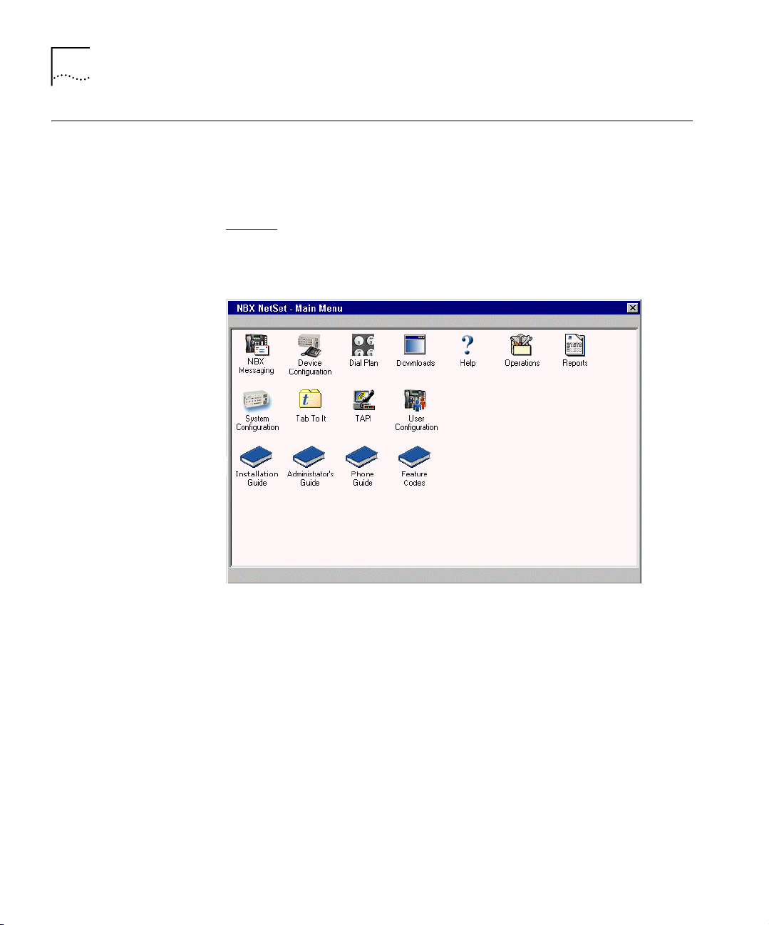
Figure 1
when you log on to the NBX NetSet utility.
Figure 1 NBX NetSet - Main Menu Window
shows the NBX NetSet - Main Menu window, which appears
NBX systems present the NBX NetSet utility through an embedded web
server. NBX NetSet passwords grant system administrators and users
different levels of access privileges.
Individual telephone users can view or change their personal settings
such as personal speed dial lists, off-site notification settings, and ringing
tones.
System administrators can manage user profiles and devices, change
system parameters, such as speed dial lists and dial plan settings, and
upgrade the system software.
Page 23
NBX NetSet Features 23
NBX NetSet Features
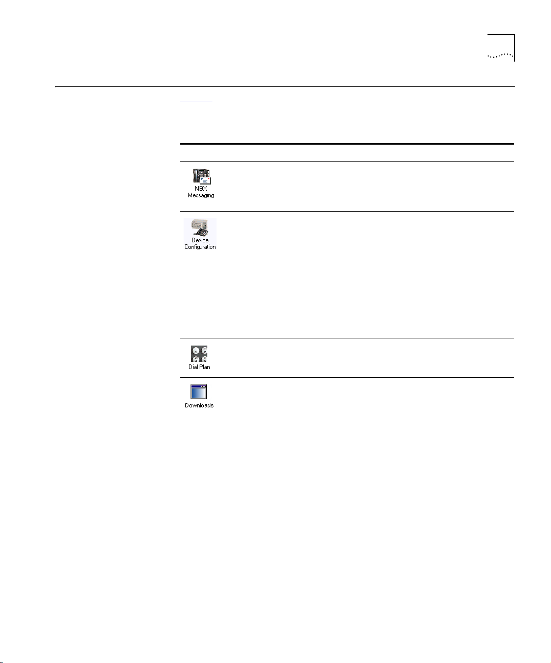
Ta bl e 4 describes the features that administrators can access through the
NBX NetSet - Main Menu window.
Tab le 4 NBX NetSet Features for the NBX Administrator
Icon Description
Configure and manage system-wide NBX Voice Messaging, Auto
Attendants, and VPIM settings. If you install a license for a third-party
messaging application and disable NBX Messaging, this icon is not
available.
Configure and manage NBX devices, such as:
■ Telephones and telephone groups
■ Analog Line Cards
■ Digital Line Cards (T1, E1, and BRI-ST cards)
■ Analog Terminal Adapters (ATAs)
■ Call Park
■ Attendant Consoles
■ Virtual Tie Lines
Configure and manage your system Dial Plan.
Download, install, configure, and manage additional system features,
such as:
■ Optional NBX software, such as NBX Call Reports and TAPI software
■ Multiple Label Makers for telephones and NBX Attendant Consoles
■ Quick Reference Guides for the NBX Business and Basic Telephones,
and analog telephones on the NBX system
■ NBX manuals including the NBX Installation Guide, NBX
Administrator’s Guide, NBX Telephone Guide, and NBX Feature
Codes Guide
Page 24
24 CHAPTER 1: INTRODUCTION
Tab le 4 NBX NetSet Features (continued)for the NBX Administrator
Icon Description
Configure and manage these system-level operations:
■ Upgrading software
■ Rebooting and shutting down the NBX system
■ Managing data (database backup and restore)
■ Viewing and managing event log files
■ Viewing and adding licenses for optional features
■ Setting regionally different information (voice-prompt language, dial
tones and cadences, and documentation language)
■ Installing third-party drivers (for example, for telephones other than
NBX Telephones)
View and manage system reports:
■ Directory lists of users
■ Device List
■ System Data
■ Call Reporting
Configure and manage the system-level settings for:
■ System Settings
■ Audio Settings
■ System-wide Speed Dials
■ Business Identity
■ Security
■ TAPI Settings
Configure settings for TAPI (Telephony Applications Programming
Interface). (Can also be configured from the System Configuration icon.)
Configure and manage:
■ Users
■ Call Pickup Groups
■ TAPI Route Points
■ Hunt Groups
■ Class of Service (CoS) Settings for users
Page 25
NBX NetSet Features 25
Ta bl e 5 describes the additional icons that appear on or below the NBX
NetSet - Main Menu window. They are shortcuts to specific areas within
the NBX NetSet utility and to some of the online documentation.
Tab le 5 NBX NetSet Shortcuts
Icon Description
The Help icon in the NBX NetSet - Main Menu window provides access
to the Contents, Index, and search features of the online Help system.
The Help icon on individual dialog boxes takes you directly to
content-specific Help in addition to accessing the global Help features.
Displays Tab To It, a window that shows all the tabs for the entire
system. Click on a tab in the Tab to It window to go directly to that tab’s
interface. The Tab To It icon also appears on most dialog boxes
throughout the NBX NetSet utility.
If you install a license for a third-party messaging application, the tab for
NBX Messaging is disabled in the Tab To It window
Opens the online (PDF) version of the NBX Installation Guide. This icon is
available in the NBX NetSet - Main Menu window only.
Opens the online (PDF) version of the NBX Administrator’s Guide (this
book). This icon is available in the NBX NetSet - Main Menu window
only.
Opens the online (PDF) version of the NBX Telephone Guide. This icon is
available in the NBX NetSet - Main Menu window, and below the User
Settings window when users log on to the NBX system.
Opens the online (PDF) version of the NBX Feature Codes Guide. This
icon is available in the NBX NetSet - Main Menu window, and in the
User Settings window when users log on to the NBX system.
Returns you to the NBX NetSet - Main Menu window.
Page 26

26 CHAPTER 1: INTRODUCTION
Page 27

2
DIAL PLAN
The NBX system’s dial plan determines how the system handles calls. It defines the set of destinations that the system can reach, how to get to these destinations, and which telephone numbers to dial to reach these destinations. This chapter provides information about understanding, developing, and managing the dial plan. It covers these topics:
■ Dial Plan Concepts and Overview
■ Dial Plan Tables
■ Dial Plan Pretranslators
■ Managing the Dial Plan Configuration File
■ Outdialing Prefix Settings
■ Managing Extensions
■ Managing Extension Lists
■ Managing Dial Plan Tables
■ Managing Dial Plan Pretranslators
■ Configuring the Dial Plan for the 4ESS Protocol (T1)
■ Overview of Voice Profile for Internet Mail
■ Configuring the Dial Plan for VPIM
■ Configuring VPIM Parameters Using NBX NetSet
■ Overview of Virtual Tie Lines
■ How to Configure a Virtual Tie Line
■ Call Rerouting for Virtual Tie Lines
■ Managing Existing Virtual Tie Lines
■ Using a VTL Password
■ Dial Plan Configuration File Commands
■ Sample Solutions Using Dial Plan Configuration File Commands
Page 28

28 CHAPTER 2: DIAL PLAN
Dial Plan Concepts and Overview
The dial plan configuration file is an ASCII text file that implements the
dial plan and specifies pretranslation (digit manipulation). The system is
shipped with several default dial plan configuration files, typically, a
3-digit and a 4-digit file for each supported country.
The dial plan configuration file includes several tables:
■ Internal — Must be table ID 1
■ Incoming — Must be table ID 2
■ Least Cost Routing — Must be table ID 3
■ Routes
■ Pretranslators
You can create additional tables if necessary.
Each dial plan table consists of a series of entries, each of which includes
a sequence of digits and the action to be performed by the NBX system in
response to sending or receiving those digits. For more information on
the Internal, Incoming, and Least Cost Routing dial plan tables, see “
Dial
Plan Tables” on page 34.
Usually, you access the dial plan configuration file and manage dial plan
operations, tables, pretranslators, and extension lists through the NBX
NetSet administration utility. If your dial plan is larger than 32,000
characters, however, you cannot edit the dial plan using the NBX NetSet
utility. You must export the dial plan, edit it, and then import it.
Before you configure the dial plan, please be sure that you understand
these concepts:
■ Call Process Flow (page 29)
■ Inbound and Outbound Call Processing (page 29)
■ NBX System Database (page 30)
■ NBX System Dial Plan (page 30)
■ Pretranslation (page 31)
■ Routing (page 31)
In addition, be sure to understand how the dial plan configuration file
can affect other parts of the NBX system. See “
System Features Affected
by the Dial Plan Configuration” on page 32.
Page 29

Dial Plan Concepts and Overview 29
Call Process Flow The dial plan configuration file is a key component of inbound and
outbound call processing. The dial plan tables in the configuration file
process incoming calls in this order:
1 Incoming Dial Plan Table
2 Pretranslator Table
The dial plan tables process outgoing calls in this order:
1 Internal Dial Plan Table
2 Least Cost Routing Table
After pretranslation (if performed), the final translation process routes the
call to the destination.
Inbound and
Outbound Call
Processing
The system routes all inbound and outbound calls through the dial plan.
Inbound Call Processing
The system processes inbound calls using the Incoming table. The system
can also use pretranslators to perform digit manipulations on incoming
calls before it uses the Incoming table.
Each pretranslator operation performs a digit manipulation operation on
the dialed digits. For incoming calls, if the DID/DDI range matches the
internal extensions, the dial plan requires no pretranslator. However, you
can use pretranslators to map nonmatching dialed numbers on an
incoming DID/DDI channel to desired internal extensions. See the
example in Customer Requirement 1 in “
Sample Solutions Using Dial Plan
Configuration File Commands” on page 116.
Outbound Call Processing
The system processes outbound calls using the Internal dial plan table or
the Least Cost Routing table.
You can add entries to the Internal dial plan table to match the system to
your service. See Customer Requirement 2 in “
Sample Solutions Using
Dial Plan Configuration File Commands” on page 116.
If you have entries in both the Least Cost table and the Internal table for
the same purpose, the behavior of the dial plan can be confusing. 3Com
recommends that you accomplish least cost routing using Internal Table
Page 30

30 CHAPTER 2: DIAL PLAN
entries. For more information, see TimedRoute Create, TimedRouteEntry
Create, and TimedRouteOperation Create later in this chapter.
NBX System Database The NBX system database contains a default dial plan that is initially
loaded at the factory and is reloaded if you purge the database. The
default dial plan for the SuperStack 3 NBX system is a 4-digit plan; for the
NBX 100, it is a 3-digit plan.
Changes that you make to any system settings, including changes made
by importing a modified dial plan configuration file, are reflected in the
database. When you reboot the system, it loads the database with any
changes that you have made.
The NBX system database includes all of the settings necessary for system
operation:
■ IP and MAC addresses for the Network Call Processor, telephones, and
line cards
■ Auto Attendant definitions and menus
■ Dial plan configuration file information
■ Voice mail settings and messages
■ Telephone extensions
■ Hardware configuration information
■ Button mappings for NBX and third-party telephones
■ Call group definitions
■ Software license information
■ User profiles
NBX System Dial Plan You can import a dial plan configuration file to provide the system with a
set of operating instructions for managing the telephone system.
Alternatively, if you have made changes to the currently loaded
instructions through the NBX NetSet utility, you can export the dial plan
configuration file to save it. You can also make changes by editing the
configuration file off-system, using any ASCII editor, and then importing
the modified file. You can easily reuse a given configuration file on many
systems. For more information, see “
Importing and Exporting Dial Plan
Configuration Files” on page 45.
Page 31
Dial Plan Concepts and Overview 31
The system is shipped with several default dial plan configuration files,
typically, a 3-digit and a 4-digit file for each country that is supported.
In addition, the file
samples.txt contains several examples that illustrate
how you can configure the dial plan configuration file to control how the
system manages incoming and outgoing calls.
Normally, you completely configure a dial plan before you start to use the
system to control the telephones. Although you can make changes later,
major changes in the dial plan can disrupt the system.
Decide whether you want to use a 3-digit or 4-digit dial plan before you
create the dial plan, autodiscover, or manually add telephones or other
devices to the NBX system.
When you import a dial plan, some parameters of the system change
immediately. Others change only when you reboot the NBX system.
3Com recommends that you reboot the NBX system each time that you
change the dial plan.
Rebooting the system disrupts service to the telephones. Plan to reboot at
a time that does not inconvenience telephone users.
Pretranslation
Routing
Pretranslation is the process of translating (or manipulating) dialed digits
before they are passed to the appropriate dial plan table for subsequent
routing. You can set the dial plan to perform pretranslation on incoming
or outgoing calls. For more information, see “
page 40
Routing specifies how a call reaches a destination. You define the routes
.
Dial Plan Pretranslators” on
for the system to use in the Routes section of the dial plan configuration
file.
When you define call routing, you can also instruct the system to perform
pretranslations (digit manipulations). Both destination routes and timed
routes have digit manipulation operations (append, prepend, replace,
stripLead, or stripTrail).
The system passes dialed digits first through the device’s Least Cost
Routing table (if there is one). If the system finds no entry there, it then
uses the Normal dial plan table. If it does find an entry in the Least Cost
Routing table, it attempts to use that entry and, even if the attempt is
unsuccessful, it does not use the Normal table.
Page 32

32 CHAPTER 2: DIAL PLAN
You can route incoming calls to the Auto Attendant port, and you can
instruct the Auto Attendant to route these calls to any internal or external
number.
CAUTION: If you configure the Auto Attendant so that it can access any
external number, you risk the possibility of toll fraud. You can reduce the
possibility of toll fraud by explicitly putting specific external numbers into
the outgoing dial plan table. This precaution prevents outside callers from
dialing any external number except the ones that you define.
There are two types of routes:
■ Destination routes — Specify the extension of a destination device.
They can also perform digit manipulation operations on the dialed
digits that resulted in the selection of this route before those digits are
dialed on the destination device.
■ Timed routes — Specify time of day and day of week criteria which,
when met, result in a particular destination route being selected.
CAUTION: If you operate the NBX system in Keyset Mode, routes are not
applicable.
System Features
Affected by the Dial
Plan Configuration
For more information, see “
TimedRoute Create” page 112, and related entries under “Dial Plan
“
DestinationRoute Create” on page 103,
Configuration File Commands” on page 100.
The dial plan configuration affects several system features:
■ Keyset Mode Operation Using the Dial Plan
■ Hybrid Mode Operation Using the Dial Plan
■ Off-Site Notification
Keyset Mode Operation Using the Dial Plan
If you map any telephone buttons that have LEDs to specific Analog Line
Card ports, you enable Keyset mode in the NBX system. Instead of dialing
a single digit (typically 8, 9, or 0) before placing an outside call, the user
presses a button to select an available Analog Line Card port. The user
defines the routing (that is, the selection of a destination device) by
pressing the button to select the Analog Line Card port; however the NBX
system controls the call using the dial plan.
You cannot map a digital line extension in Keyset mode.
Page 33

Dial Plan Concepts and Overview 33
The NBX system applies any Class of Service restrictions that are
associated with the user's telephone to determine whether to make a
call. The system also uses any pretranslator that a device uses and
performs any required digit manipulation operations before it actually
transmits the digits on the Analog Line Card or Digital Line Card port.
Hybrid Mode Operation Using the Dial Plan
If you map telephone buttons for some telephones but not others, you
enable Hybrid mode (a mixture of standard and Keyset behaviors). The
system provides a system-wide External Prefix setting, which allows the
administrator to establish a prefix.
Off-Site Notification
The NBX system uses off-site notification to notify users when new voice
mail messages arrive. You can define notification devices and assign them
in the Internal dial plan as well as through the NBX NetSet utility.
Example: When voice mail arrives, the NBX system dials the telephone
number of the user’s pager. Typically, you use a system-wide prefix to
designate the device or devices you want to use for outdialing purposes,
including off-site notification calls.
Example: If the user’s pager number is 800-555-3751, and the
system-wide prefix digit is 9, the system dials 98005553751 to send
a call to the user’s pager.
To tell the system to dial a single Line Card port or a restricted number of
Line Card ports, create a suitable pool of Line Card ports for that purpose,
and then use an existing set of dial plan table entries (such as the entries
that begin with 8) or create a new set of entries to allow the dial plan
devices to route calls via the selected line card ports.
Example: You set up one 4-port card to handle all off-site notification calls.
You create a set of entries in the Internal dial plan table that each start
with the digit 8. You define a route to the 4-port card for all of these dial
plan entries so that whenever the system acts on one of these entries, it
uses one of the 4 ports on that card to dial out and notify the user.
To apply different off-site CoS restrictions to different users, you need
multiple dial plan entries. If you are not trying to apply the CoS
restrictions, then a single dial plan entry is sufficient.
Page 34

34 CHAPTER 2: DIAL PLAN
Dial Plan Tables Dial plan tables contain information that controls how the system routes
calls. Each dial plan configuration file consists of at least three dial plan
tables. This section discusses these topics:
■ Dial Plan Command Format
■ Internal Dial Plan Table — Must be table ID 1
■ Incoming Dial Plan Table — Must be table ID 2
■ Least Cost Routing Dial Plan Table — Must be table ID 3
■ Adding New Dial Plan Ta ble s
CAUTION: Tables 1, 2, and 3 must exist. Do not delete them. You may
create additional dial plan tables if necessary, but they must be numbered
4 or higher.
If the Least Cost Routing table exists, it takes precedence over the Internal
table. If the system cannot find a Least Cost Routing table, it attempts to
find a corresponding entry in the Internal table. If you have entries for the
same purpose in both the Least Cost and Internal tables, the behavior of
the dial plan can be confusing.
Dial Plan Command
Format
Dial Plan Command Format” next for a description of dial plan
See “
command syntax and structure. For a complete list and description of dial
plan commands, including command arguments and examples, see “
Dial
Plan Configuration File Commands” on page 100.
Each dial plan table contains a sequence of commands. These commands
collectively determine how calls are handled.
Most of the dial plan commands have a very similar format, as shown in
Figure 2
.
Page 35

Figure 2 Dial Plan Command Format
Dial Plan Tables 35
Leading Digits to Collect
Table Entry ID Number
Tabl e N am e
Tab le I D N um ber
Call Classification
with Class of Service
Maximum and Minimum
Characters to Collect
—
Used
Number of the
route (dial tone
facility) from
Routing Tables
Priority
(Not Used)
Command
Table Create 1 Internal
/ Id Entry Digits Min Max Class Prio Route
/
TableEntry Create 1 1 0 1 1 Internal 0 4
TableEntry Create 1 2 1 3 3 Internal 0 0
TableEntry Create 1 3 2 3 3 Internal 0 0
Table Create 2 Incoming
/ Id Entry Digits Min Max Class Prio Route
/
TableEntry Create 2 1 0 1 1 Internal 0 4
TableEntry Create 2 2 1 3 3 Internal 0 0
Table Create 3 Least Cost Routing
/ Id Entry Digits Min Max Class Prio Route
TableEntry Create 3 1 91607387 12 12 LongDistance 0 10
Ta bl e 6 describes each field of a dial plan command.
Tab le 6 Dial Plan Command Fields
Field Description
Command Command name. For example, TableEntry Create is the command that make Class of Service
and call routing decisions based on the correspondence of dialed digits and table entry digits.
See “
Dial Plan Configuration File Commands” later in this chapter for a description of each
command.
Table ID Number Table ID number. This is always 1 for the Internal dial plan table, 2 for the Incoming dial plan
table, and 3 for the Least Cost Routing Table.
Page 36

36 CHAPTER 2: DIAL PLAN
Tab le 6 Dial Plan Command Fields (continued)
Field Description
Table Entry ID
Number
Digits One or more digits that begin the dial sequence. Either single or multiple entries can start
Min Minimum number of digits that the system collects before routing the call.
Max Maximum number of digits the system collects before routing a call.
Class Class of Service (CoS). The system uses this information to decide whether a caller is allowed
Priority Priority number. This field is not used at this time, but must be present and should always be
Route Route number. This identifies an entry in the Routes section of the dial plan. Zero is a typical
Table entry number (a unique number for each entry in the table). These numbers are usually
in ascending order in the table, but you can change the order. For example, you might want
to place a new item near other items of the same type (that begin with the same digit) in
order to help you when you troubleshoot the configuration file.
with the same digit. The system uses this field in conjunction with Min and Max to determine
when to make the call routing decision.
Most sample tables have a single entry for digit 0 (zero) to specify how the system handles a
telephone number which has zero as the first digit.
If you want the system to handle calls differently, depending on whether they start with 90
or 91, you must have one entry in the table for each of these 2-digit sequences.
to make this specific type of call. The possible classifications are:
Internal, Local, LongDistance, International, WAN, Toll- Free, Emergency, COCode,
Wireless, Toll, Operator, AlternateLong, TrunkToTrunk, Diagnostics, NotAllowed, Other
Each of these values corresponds to a selection in the NBX NetSet utility.
0 (zero).
value for internal calls, and indicates that this call uses no route, in which case, digits are
transmitted as soon as they are dialed.
If a new entry in the Internal table appears not to work, it is possible that
the system is using an entry from the Least Cost table instead. To avoid
such conflicts, you can accomplish least cost routing using only the
Internal table. 3Com strongly recommends that, to keep the dial plan as
simple as possible, you use only the Internal table for least cost routing.
For more information on how to use the dial plan configuration file,
Managing the Dial Plan Configuration File” on page 44.
see “
Basic Dial Plan Table Examples
These examples describe the basic operation of a dial plan table.
Example: If you are using a 4-digit dial plan and the telephone
extensions start with 2, then the table entry with 2 in the Digits column
typically has 4 in the Min column. Before making a decision, the system
Page 37

Dial Plan Tables 37
would collect all 4 digits of the extension. If the caller dials fewer than the
Min number of digits, the system times out in 20 seconds.
Example: If Digits = 2, Min = 4, and Max = 4, the system knows that if
the first digit is 2, it must collect no less than 4 and no more than 4 digits
before making the call routing decision.
If the caller dials at least the minimum number of digits and not more
than the maximum number of digits, the system waits 5 seconds and
then routes the call based on the digits dialed.If the caller dials more than
the maximum number of digits, the system attempts to place the call.
Often, Max value and the Min value are identical, because you want the
system to collect a specific number of digits, no more and no less.
Example: For internal extensions, you want the system to collect exactly
3 digits (4 in a 4-digit dial plan) before making a decision, so you would
set both Min and Max to 3 (4 in a 4-digit dial plan).
The two columns may be different if the table entry applies to more than
one situation.
Example: In the United States, the Min value for the 90 entry is 2,
because 90 allows an internal caller to reach a telephone company
operator (9 to get an outside line, and then 0 to get the operator). The
Max value is 64, because the caller can continue to dial after the zero,
entering a number to call, plus a telephone credit card number, and
possibly an identification code number.
If the caller dials only 90 (which satisfies the minimum of two digits) and
stops dialing, the system waits for 5 seconds. If no other digits are
entered, the system connects the caller to the operator.
If other digits are dialed, the system accepts them up to the limit of 64. If
the caller stops after dialing fewer than 64 digits, the system again waits
5 seconds before acting on the dialed sequence of digits.
Example: You can assign a new employee to the Default User Group.
You can then set the permissions for that group so that group members
have permission to make LongDistance calls when the system mode is
Open or Lunch, but not when the system mode is Closed or Other.
Page 38

38 CHAPTER 2: DIAL PLAN
Example: You can assign the company’s Vice President of Finance to a
group that you name the All Privileges Group. You can set the
permissions for that group so that group members have permission to
make LongDistance calls during all system modes.
Internal Dial
Plan Table
The Internal dial plan table (table ID 1) defines how to handle calls placed
from internal devices, such as NBX Business or Basic Telephones, to a
destination. A destination can be another internal device, such as a local
telephone, or an external telephone line (Analog Line Card or Digital Line
Card) that connects the NBX system to other facilities.
The Internal dial plan table consists of a series of commands. For an
example of the command format, see “
earlier in this chapter. Ta bl e 6
command. Ta bl e 7
Tab le 7 Predefined Routes
Route Number Description
1 Local CO (strip)
2 Local CO (no strip)
3 Voice Application (Auto Attendant on extension 500)
4 Attendant (person)
5 H.323 Gateway
6 Least Cost Route example
Other User-defined routes
describes the predefined routes.
on page 35 describes each element of the
Dial Plan Command Format”
You cannot delete or modify predefined routes, only create new routes.
Incoming Dial
Plan Table
Each device must have a Normal table. The Least Cost Routing table is
optional. Telephones use the Internal dial plan table (table ID 1) as their
normal outbound table and the Least Cost Routing table (table ID 3) as
their long distance routing table.
The Incoming dial plan table (table ID 2) defines how calls arriving from
outside the NBX system are routed to extensions. Incoming calls can
arrive on analog telephone lines or through Digital Line Card ports.
The incoming dial plan table consists of a series of commands. For an
example and basic understanding of the command format, see “
Dial Plan
Page 39

Dial Plan Tables 39
Command Format” on page 34. For a description of the each element of
a dial plan command, see Ta bl e 6
on page 35.
By default, Line Card ports, Digital Line Card ports, and H.323 gateways
use the Incoming dial plan table as their normal dial plan table. An
Incoming dial plan table typically has a more restricted list of dialable
digits than the Internal dial plan table. You usually cannot dial extensions
associated with internal paging or Analog or Digital Line Card ports.
Least Cost Routing
Dial Plan Table
The Least Cost Routing table (table ID 3) defines how to route calls in
order to minimize the cost of those calls.
Example: You might use two different long distance carriers, one for a
specific geographic region, and one for all other areas of the country. In
the Least Cost Routing table, you can create entries that route calls
differently for those two geographic areas. Each country uses a different
method to accomplish this. In the United States, you can specify the area
codes that apply to a geographic region. In France, you can specify a
carrier by adding prefix digits to the telephone number.
By default, internal telephones specify the Least Cost Routing table as
their least cost table. Typically, devices associated with the Incoming dial
plan table (Line Card ports, Digital Line Card ports, and H.323 gateways)
do not use the Least Cost Routing table.
The Least Cost Routing table is optional. If it does not exist, the system
uses the Internal table routing destinations. If you have entries in both the
Least Cost and Internal tables for the same purpose, the behavior of the
dial plan can be confusing. Therefore, 3Com recommends that you
accomplish least cost routing using Internal Table entries. See TimedRoute
Create, TimedRouteEntry Create, and TimedRouteOperation Create.
Example: If a new entry in the Internal table appears not to work, it is
possible that the system is using an entry from the Least Cost table
instead. To avoid such conflicts, accomplish least cost routing using only
the Internal table. 3Com strongly recommends that you keep the dial
plan as simple as possible by using only the Internal table.
Page 40

40 CHAPTER 2: DIAL PLAN
Adding New
Dial Plan Tables
If you are sharing the system with another company or group and want
to control calls differently at the two sites, you can add a fourth table.
Example: You assign one extension range to Company A and a different
range to Company B. The fourth table controls the extension range for
Company B, so that outbound calls from Company B’s extensions use
only their external telephone lines.
You might also need a fourth table if a single company had two sites but
only one NBX system. In order to properly route emergency (911) calls,
you use the fourth table to define which extensions use each dedicated
911 telephone line.
Example: Users at site A dial 911 and the system uses the Internal table
(table ID 1) to make the emergency call on one external telephone line.
Users at site B dial 911 and the system uses table ID 4 to make the
emergency call on a different external telephone line. The emergency
staff know, based on the dialing number, which site has the emergency.
Enhanced 911, E911, is available in some areas. This service enables
emergency staff to identify the specific location of the emergency. For
example, in a campus of buildings, the emergency staff can identify the
specific building, floor, and location from which the emergency call
originated. The NBX system supports E911 over ISDN. The administrator
must define an outbound call pretranslator to provide the specific
extension number from which the 911 call originated.
Dial Plan Pretranslators
The system uses pretranslators to modify digit sequences of incoming or
outgoing calls. On incoming calls, pretranslators can map the entire
dialed number (including area code) to an internal extension number.
For example, an external party dials 978-555-0101 to reach the person
on extension 101. Pretranslators ensure that the proper digits are
mapped to the correct extension number.
For more information, see:
■ Pretranslators for Incoming Calls on page 41
■ Pretranslators for Certain Outgoing Calls on page 42
A typical pretranslator function involves mapping incoming DDI/DID
telephone calls to internal extension numbers.
Page 41

Dial Plan Pretranslators 41
Example: Say that the DDI/DID telephone numbers range from
508-555-4200 through 508-555-4299. The telephone company sends
you the last 4 digits of the total telephone number. Internally, you want
to use extensions 2000 through 2099. You can define a pretranslator to:
■ Remove (stripLead) the first two digits of the incoming 4-digit
sequence.
■ Add (prepend) the digits 20 in front of the remaining 2 digits.
Managing Dial Plan Pretranslators” on page 64 for detailed
See “
information and examples on creating and managing dial plan
pretranslators.
Pretranslators for
Incoming Calls
For incoming calls, pretranslation reformats the dialed number before it is
passed to the Incoming dial plan table (Table ID 2). See “
Incoming Dial
Plan Table” on page 38.
Incoming Pretranslator Example 1
If, for an incoming telephone call, the telephone company passes you
4-digit numbers from 6100 through 6199, the system can use a
pretranslator to remove the first digit; the remaining 3 digits can then be
used as internal extension numbers in a 3-digit dial plan. Tell the system
which pretranslations you want to perform by defining digit manipulation
operations (append, prepend, replace, stripLead, or stripTrail) within the
PreTranslator section of the dial plan configuration file.
Incoming Pretranslator Example 2
Assume the telephone company passes 10-digit numbers to the system
for each incoming telephone call (for example, numbers in the range
4567-89-3000 to 4567-89-3500). If the system uses 4-digit extensions in
the range 2000 to 2500, you could pass an incoming 10-digit number
such as 4567-89-3210 to extension 2210.
This strategy requires two pretranslation operations: The first operation
performs a stripLead operation to remove the initial 7 digits, leaving 210.
The second operation prepends the number 2 in front of the remaining 3
digits. The result is 2210, which matches an extension within the
extension range. “
Sample Solutions Using Dial Plan Configuration File
Commands” on page 116 shows how to accomplish this pretranslation
using the dial plan configuration file.
Page 42

42 CHAPTER 2: DIAL PLAN
Each device can specify only one DDI/DID pretranslator and one CLIP
pretranslator. To create or modify a pretranslator, you either edit a dial
plan configuration file and import it, or use the NBX NetSet utility and
modify an existing dial plan configuration file.
The system performs operations in ascending order of operation ID.
Operations are both sequential and cumulative.
You can also use pretranslators with virtual tie lines to link multiple
NBX systems. Incoming calls within a defined numeric range arrive at the
first system, are modified through digit manipulation operations, and are
then routed to a tie line connected to a second system.
Each sample dial plan that is shipped with the system includes a default
pretranslator.
Pretranslator Example 3
Assume that the telephone company passes 4-digit numbers to the
system for each incoming telephone call (for example, numbers in the
range 5200 through 5300). If the system uses 3-digit extensions in the
range 200 through 300, you could define a single pretranslation
operation to stripLead (remove) the first digit, for instance, the number 5
from an incoming number such as 5278, and pass the call to extension
Sample Solutions Using Dial Plan Configuration File Commands”
278. “
on page 116
shows how to accomplish this pretranslation using the dial
plan configuration file.
Pretranslators for
Certain
Outgoing Calls
On outgoing calls using an ISDN PRI card, pretranslators allow the
external called party to identify the full number of the internal calling
party, including the area code. For example, if the person on extension
101 within a company calls an external number, the caller’s entire number
is displayed to the called party when Calling Line ID Presentation (CLIP)
pretranslators are used. Pretranslation reformats the outgoing dialed
number before it is passed to the Internal dial plan table (Table ID 1) or
possibly the Least Cost Routing table (Table ID 3). For more information,
Internal Dial Plan Table” on page 38 and “Least Cost Routing Dial
see “
Plan Table” on page 39.
Example: If the DDI/DID telephone numbers range from 508-555-4200
through 508-555-4299, internally, you dial extensions from 2000
through 2099 to reach another internal telephone.
Page 43

Dial Plan Pretranslators 43
When you place a call to an external telephone number, the system can
use these pretranslator steps to create the full 10-digit number:
1 Remove (stripLead) the first two digits (20) from the internal extension
number of the telephone making the call.
2 Add (prepend) the digit sequence 50855542 to the two remaining digits,
creating the full DDI/DID telephone number.
3 Pass the full number to the telephone company.
Example: To transmit Calling Line ID Presentation (CLIP) information on
outgoing calls, you can define a pretranslator that transforms internal
extensions into full telephone numbers (the numbers that someone
external to the company uses to dial in). Assume that you are using
telephone extension numbers from 1000 to 1099 and that only the last
two digits match the DDI/DID (Direct Inward Dial/Direct Dial Inward)
numbers that are assigned to the company. You can define a
pretranslator to remove (stripLead) the first two digits from the internal
extension number and add (prepend) the appropriate digit string. This
pretranslator constructs the full telephone number.
Example: If you use two different long-distance carriers at different times
of the day to save costs, you can prepend different digit sequences to the
outgoing dialed number to select which carrier you want. If you prepend
1010321 between the time the business opens and 3:00 p.m., you select
one long-distance carrier. If you prepend 1010220 from 3:00 p.m. until
the next time the business opens (including weekends), you select the
other carrier and obtain a lower rate.
To tell the system which outgoing pretranslations you want to perform,
you define digit manipulation operations (append, prepend, replace,
stripLead, or stripTrail) in the Routes section of the dial plan configuration
file. You can define these commands for both destination routes and
timed routes. For more information on configuring pretranslators, see
Managing Dial Plan Pretranslators” on page 64.
“
Page 44

44 CHAPTER 2: DIAL PLAN
Managing
the Dial Plan
Configuration File
Accessing the
Dial Plan
Creating Dial Plan
Configuration Files
This section describes the dial plan configuration file and how to manage
it. From the Operations tab of the Dial Plan window, you can perform
these tasks:
■ Accessing the Dial Plan
■ Creating Dial Plan Configuration Files
■ Importing and Exporting Dial Plan Configuration Files
■ Importing a User-Defined Dial Plan
■ Exporting (Saving) a Dial Plan Configuration File
■ Testing a Dial Plan
■ Generating a Dial Plan Report
■ Modifying a Dial Plan Configuration File
To import a dial plan configuration file and modify it, select NBX NetSet
> Dial Plan > Operations. From this tab, you can access
customer-defined and default dial plans.
The simplest way to create a new dial plan is to model it after an
existing one.
1 Go to the Operations tab.
2 Browse for a dial plan, or select one from the pull-down list.
3 Click Open to open the file in your browser.
4 Click Save As and save the dial plan as a new file.
You can now edit the file with an ASCII editor. After you customize the
new dial plan, Import it to the NBX system. see “
Importing and Exporting
Dial Plan Configuration Files” on page 45.
3Com recommends that you enter these commands at the top of every
dial plan configuration file:
Table Delete *
DestinationRoute Delete *
TimedRoute Delete *
PreTranslator Delete *
Page 45

Managing the Dial Plan Configuration File 45
When you subsequently import this dial plan, these commands purge any
traces of the old dial plan and prevent any conflicts that can result from
importing one dial plan on top of an existing one.
You create new entries in the dial plan configuration file by typing in new
commands (see “
Dial Plan Configuration File Commands” on page 100)
or by cutting, pasting, and editing existing lines in the file.
When you cut and paste new lines into dial plan tables, be sure to change
the Entry number in the pasted line. If two or more lines have the same
Entry number, only the last one takes effect.
Importing and
Exporting Dial Plan
Configuration Files
You import a dial plan configuration file either to implement changes you
have made by editing the file, or to reload a previously saved
configuration.
From the Operations tab of the Dial Plan window, you can:
■ Import a North American Dial Plan
■ Import an International Dial Plan
This section concludes with a discussion of International Dial Plan Issues.
When you export the working dial plan, the NBX system constructs a new
configuration file from the values in the database and displays it. The new
file shows the current date and time. You name the file when you save it.
The sample default files include examples of such things as timed routes
and pretranslators. To preserve the default (sample) dial plan
configuration included with the system, 3Com advises you to choose a
unique file name different than any of the default (sample) dial plan
configuration files so that you do not overwrite the sample default files.
Import a North American Dial Plan
The default dial plan for the SuperStack 3 NBX system is
NorthAmerica-4-digit.txt. The default dial plan for the NBX 100
system is
NorthAmerica.txt. Some customized dial plans are provided
for use in other countries.
Always read the system Release Notes (called
up-to-date information on dial plans.
readme.txt) for the most
Page 46

46 CHAPTER 2: DIAL PLAN
To import a default dial plan configuration file:
1 In the NBX NetSet – Main Menu window, click Dial Plan. The Dial Plan
window appears, displaying the Operations tab.
2 Click the
Default File radio button. From the Default File pull-down list,
select the default file that you want to use.
3 Click
Import.
4 Reboot the system.
CAUTION: When you import a dial plan configuration file, the
NBX system immediately implements the dial plan. You are always
warned that the system may become inoperative. The system becomes
inoperative only if you have manually modified a dial plan and have
made syntax or content errors. Carefully check any changes that you
make to the configuration file before you import.
Import an International Dial Plan
To change the default North American dial plan to a country-specific dial
plan:
1 In the NBX NetSet – Main Menu window, click Dial Plan. The Dial Plan
window appears, displaying the Operations tab.
2 Click the
Default File radio button.
3 In the list next to the Default File button, select the default file that you
want to use.
4 Click
Import.
CAUTION: When you import a dial plan configuration file, a message
warns you that the dial plan may become inoperative. The system
becomes inoperative only if you have manually modified a dial plan and
have made syntax or content errors. Carefully check any changes that you
make to the configuration file before you import.
5 Click Yes. The system imports the new dial plan and produces a report of
any errors.
6 Reboot the system.
You may see a warning that “destination extension list is empty.” This
means that a particular type of device is not installed. You may safely
ignore this type of warning.
Page 47

Managing the Dial Plan Configuration File 47
International Dial Plan Issues
Several international dial plan issues warrant attention. See these topics:
Customizing an International Dial Plan. If there is no customized
dial plan for your country, you may need to modify the default dial plan.
Modifying a Dial Plan Configuration File” on page 51. If you edit the
See “
default dial plan, you can test the changes by making a simulated call.
Testing a Dial Plan” on page 49.
See “
Autodiscovering Internal Telephones. The default dial plan for the
NBX 100 allows you to allocate internal telephones to extension numbers
100 through 449. The default dial plan for the SuperStack 3 NBX system
allows you to allocate internal telephones to extension numbers 1000
through 3999. If you autodiscover your company’s internal telephones,
Auto Discovery usually begins at number 100 or 1000. However, for
some countries, internal telephones begin at a higher number to allow
you to directly dial numbers of “national importance.” Auto Discovery
allocates telephone extensions numbers within this range. For more
information on Auto Discovery, see “Using Auto Discovery for Initial
System Configuration” in the NBX Installation Guide.
Importing a
User-Defined Dial Plan
Dialing Outside Lines. To obtain an outside line, dial 9 or 0 as
appropriate for your country.
WARNING: You must first obtain an outside line before you can dial
emergency numbers.
To import a customer-defined (user-defined) dial plan configuration file:
1 In the NBX NetSet – Main Menu window, click Dial Plan. The Dial Plan
window appears, displaying the Operations tab.
2 In the User-Defined File box, enter the path and name of the user-defined
configuration file, or click
Browse to find the file that you want.
The NBX system has no predefined location for dial plan configuration
files. You can specify any directory or path that you want.
3 Click
Import and reboot the system.
CAUTION: When you import a dial plan configuration file, the
NBX system immediately implements the dial plan. You are always
warned that the system may become inoperative. The system becomes
inoperative only if you have manually modified a dial plan and have
Page 48

48 CHAPTER 2: DIAL PLAN
made syntax or content errors. Carefully check any changes that you
make to the configuration file before you import them.
Exporting
(Saving) a Dial Plan
Configuration File
When you export (save) the current configuration, the system creates
a new dial plan configuration file from the current database. You save the
new text file using a name that you choose.
This example refers to Internet Explorer. If you use another browser, you
may need to use slightly different procedures.
To export a dial plan configuration file:
1 In the NBX NetSet – Main Menu window, click Dial Plan. The Dial Plan
window appears, displaying the Operations tab.
2 Click
Export. The system constructs a new configuration file from the
current values in the database and displays it. Figure 3
shows a partial
display. Scroll your browser window to see your complete dial plan.
Figure 3 Dial Plan Configuration File (partial)
3 Click the File menu and select Save As.
4 From the list box at the top of the Save As window, select the destination
folder.
5 In the File Name text box, replace the default file name with a new name.
Page 49

Managing the Dial Plan Configuration File 49
The sample default files include examples of such things as timed routes
and pretranslators. Verify that you rename the new configuration file with
a unique file name so that you do not overwrite the sample default file.
6 Click Save.
Testing a Dial Plan This section describes how to test the currently loaded dial plan by
placing a simulated call.
Even if the NBX system is completely installed and operational, a test
places a simulated, not an actual call.
Example: If you have an entry in the dial plan for digit sequences starting
with 91, with MIN and MAX set to 5, and you test the sequence 9123,
the dial plan test reports an insufficient number of digits. However, in
actual operation, the NBX system would time out waiting for the fifth
digit, and then attempt to place the call. Assuming that the outside line
prefix is 9 (such as in the United States), this situation would obtain an
outside line (9) and then dial the numbers 123.
You can specify a day of the week and a time by selecting entries from
the Day/Time list boxes. This choice instructs the system to act as if the
day and time you select are the current day and time.
If you have timed routes defined in the dial plan, you use different day
and time settings to determine whether the timed route works properly.
Example: Assume that you want a timed route to select route 35 during
open business hours Monday through Friday, but route 36 when business
is closed on those days and on weekends. After you define the timed
route commands and import the modified file, you then test using days
and times within business hours (to verify that the system selects route 35)
and during closed hours and weekends (to verify that it selects route 36).
You can also use day and time settings to test whether the Class of
Service settings operate as expected.
Example: You can configure the dial plan to allow toll calls from an
extension during open business hours, but to disallow such calls when
the business is closed and on weekends. Test using days and times within
business hours (to confirm that you can make toll calls from that
extension) and during closed hours and weekends (to confirm that the
system prevents such calls).
Page 50

50 CHAPTER 2: DIAL PLAN
To create and run a test using the currently loaded dial plan:
1 In the NBX NetSet – Main Menu window, click Dial Plan. The Dial Plan
window appears, displaying the Operations tab.
Generating a
Dial Plan Report
2 Click
Test . The Tes t Dial Plan dialog box appears.
3 To set up the simulated call, from the Device to dial from list box, select
the number from which you want to dial.
4 In Number to dial, enter the number that you want the system to dial.
5 Select the desired date and time in the Day/Time pull-down lists.
For some tests, the day and time settings are irrelevant. You can leave the
settings at their default values (Sunday, 00, and 00).
6 Click Tes t. The test runs and the results appear in the dialog box.
This section describes how to create a report containing all dial plan
settings, tables, routes, and pretranslators. The report also performs
a consistency check to ensure that all dial plan table entries point to valid
routes which, in turn, point to valid extensions. The report also identifies
how many devices are using each dial plan table and each pretranslator.
Consider these common dial plan problems:
■ Dial plan table entries that point to nonexistent routes
■ Timed route entries that point to nonexistent destination routes
■ Destination route entries that point to nonexistent extensions or
empty extension lists
■ Timed route entries that overlap
■ Devices that do not specify a normal table
■ Devices that point to nonexistent Normal tables, Least Cost Routing
tables, or pretranslators
■ Pretranslator entries that have no operations
If a telephone has no table assigned, that telephone does not have
permission to dial. This error is flagged in Reports. If a device has only a
Normal table, no error is reported.
If a device has only a Least Cost table, an error is reported. The telephone
is still usable and has permissions defined in whatever table has been
chosen as Least Cost. If a device has both a Normal and Least Cost table,
no error is reported (the usual condition).
Page 51

Managing the Dial Plan Configuration File 51
When the NBX system detects an error in any line of an imported dial
plan configuration file, it ignores that line and continues to process all
remaining lines in the file. This precaution minimizes the impact of errors
on the dial plan.
To generate a dial plan report:
1 In the NBX NetSet – Main Menu window, click Dial Plan. The Dial Plan
window appears, displaying the Operations tab.
Modifying a Dial Plan
Configuration File
2 Click
Report. The dial plan report appears. Scroll up and down the
browser window to see the full display.
3 Click Close.
The person validating the dial plan test is responsible for verifying that the
test call used the correct dial plan table and dial plan table entry.
To record test results and send them to someone, select the text in the
results pane and use the browser’s copy function (typically found in the
Edit menu) to copy the test results to another application window, such
as an editor or e-mail.
Errors can prevent calls from being successfully routed. Warnings are
conditions that you can easily correct to successfully route the call.
4 When you are finished, click Close at the bottom of the screen.
This section describes how to modify the currently loaded dial plan
configuration file.
CAUTION: Modifications must be syntactically correct. Each time that the
system imports a dial plan configuration file, it verifies the file for errors
and displays the results. To avoid typing mistakes, 3Com suggests that
you start with an existing dial plan (for example, one of the default plans
that are shipped with the NBX system or a plan from another NBX
system), modify it, and save it as a renamed file.
To modify a dial plan configuration file:
1 In the NBX NetSet – Main Menu window, click Dial Plan. The Dial Plan
window appears, displaying the Operations tab.
2 Click
Modify. The Modify Dial Plan dialog box shows a partial display.
Scroll up and down the browser window to see the complete dial plan.
Page 52

52 CHAPTER 2: DIAL PLAN
3 Edit the dial plan configuration file. A single line of space is required
between each dial plan entry. You can type a complete dial plan entry
anywhere in the file.
4 Click OK. The Import Confirmation dialog box prompts you to confirm
the changes.
5 Click Yes. The system imports the modified dial plan. The Dial Plan
Consistency dialog box appears, displaying the results of the error and
consistency checks.
6 Make a note of any errors, and correct them by editing the file.
You may be required to make changes based on warning messages.
7 Click Close.
Outdialing Prefix Settings
Managing Extensions
Extension Settings
Overview
A telephone user can look up a call in the call logs (Missed Calls,
Answered Calls, and Dialed Calls) using the telephone display panel,
select a telephone number from any of the logs, and redial it.
To redial a number from the Missed Calls or Answered Calls list, the NBX
system needs to know the appropriate dial prefix to prepend to the digits
in the telephone number.
For information and examples about how to configure outdialing
prefixes, see the Help at NBX NetSet > Dial Plans > Operations >
Outdialing Prefixes.
This section describes how to add, change, and manage extensions:
■ Extension Settings Overview
■ Changing Extension Length and Ranges
■ How Auto Discovery Assigns Extensions
■ Modifying Extensions
The NBX system establishes connections between extension numbers.
The concept of an extension applies to more than just telephones.
Extensions are also assigned to NBX applications such as Call Park zones,
Auto Attendants, hunt groups, Line Card ports, voice mail ports, and
Page 53

Managing Extensions 53
virtual devices such as the pcXset™ PC soft telephone Client and the
ConneXtions H.323 Gateway.
The extension length (either 3 or 4), which applies to all extensions on a
system, indicates that all extensions contain that number of digits. You
cannot mix 3-digit and 4-digit extensions within the same NBX system.
The NBX 100 and the SuperStack 3 NBX systems both support 3-digit and
4-digit dial plans, although there are some differences in the extension
ranges as noted in these tables. By default, the NBX 100 uses a 3-digit
dial plan, and the SuperStack 3 NBX uses a 4-digit dial plan.
Ta bl e 8
Ta bl e 9
lists typical extension ranges in a 3-digit and a 4-digit dial plan.
describes these ranges in more detail and gives the default ranges
and values for 3-digit and 4-digit dial plans.
Tab le 8 Typical Extension Ranges for 3-digit and 4-digit Dial Plans
Extension Type 3-digit 4-digit
Telephones NBX 100:
100–449
Auto Attendant 500–599 500, 501, plus 5500–5599
Hunt Group NBX 100:
450–499
External Extensions
(includes line card
ports and Call Park)
Call Park (must fall
within External
Extension range)
Note 1: The NBX 100 is shipped with a factory default 3-digit dial plan. If you import
any 4-digit plan, you must manually specify any 4-digit extension ranges that are not
set by the imported plan. You must also manually change any device extensions so
that they fall within the appropriate range.
Note 2: The Superstack 3 NBX is shipped with a 4-digit dial plan. If you import any
3-digit plan, you must manually specify any 3-digit extension ranges that are not set
by the imported plan. You must also manually change any device extensions so that
they fall within the appropriate range.
Note 3: TAPI Route Point extensions occur in the same range as telephones. TAPI
Route Point extensions do not appear in telephone lists within the NBX NetSet utility.
For more information about TAPI Route Points, see TAPI Route Points
600–799
(external Auto Discovery
starts at 750)
NBX 100:
601–609
SuperStack 3 NBX:
1000–3999
SuperStack 3 NBX:
4000–4099
6000–7999
(external Auto Discovery
starts at 7250)
SuperStack 3 NBX:
6000–6099
on page 263.
Page 54

54 CHAPTER 2: DIAL PLAN
Ta bl e 9 provides a more detailed explanation of extension types, including
default extension ranges and values for 3-digit and 4-digit dial plans.
Tab le 9 Dial Plan Extension Settings
Field Purpose (See Notes 1 and 2)
Telephone
Extensions Range
Auto Attendant
Extensions Range
Default Auto
Attendant
Extensions
Hunt Group
Extensions Range
The range of extensions for telephones.
■ SuperStack 3 NBX: 1000–3999
■ NBX 100: 100–449
TAPI route point extensions are included in the telephone
extensions range.
Length — This pull-down field specifies the number of digits for
telephone extensions.
The range of extensions for Auto Attendants.
Default:
SuperStack 3 NBX: 5500–5599
NBX 100: 500
–599
For both 3-digit and 4-digit dial plans:
■ Extension 500 is reserved as the default Auto Attendant.
■ Extension 501 is reserved as the voice mail Auto Attendant.
Default extension that the NBX system assigns to the default
Auto Attendant. The Auto Discovery process assigns this
extension.
The system must direct each call coming in on an external line to
an extension. During the Auto Discovery of external lines
(analog lines and Digital Line Card channels), the NBX system
assigns the default extension (500) as the Auto Attendant
extension. After you import the dial plan configuration file and
complete the Auto Discovery process, you can manually
configure the extension for each analog line and each Digital
Line Card channel, if you want.
For both 3-digit and 4-digit dial plans:
■ Extension 500 is reserved as the default Auto Attendant.
■ Extension 501 is reserved as the voice mail Auto Attendant.
The range of extensions for hunt groups.
■ SuperStack 3 NBX: 4000–4099
■ NBX 100: 450–499
Page 55

Managing Extensions 55
Tab le 9 Dial Plan Extension Settings (continued)
Field Purpose (See Notes 1 and 2)
External
Extensions Range
The range of extensions that are connected to external devices,
such as Analog Line Card ports, Digital Line Card ports (BRI-S/T,
T1, E1, ISDN PRI), Call Park, and Paging extensions.
Default:
■ SuperStack 3 NBX: 6000–7999
■ NBX 100: 600–799
Call Park
Extensions Range
The range of extensions for Call Park. This feature allows the
user to temporarily park a telephone call and then pick it up at a
different telephone. Call Park extensions must be a subset of
external extensions.
■ SuperStack 3 NBX: 6000–6099
■ NBX 100: 601–609
Start External
Discovery At
The extension to use when autodiscovering external devices.
The system assigns extensions starting with this number and
incrementing upward as they are discovered. If the highest
extension is reached, the system starts looking from the
beginning of the external range and selects the first unused one.
Typically, systems do not use all of the available external
extensions from 600–799 in a 3-digit dial plan or from
6000–7999 in a 4-digit dial plan.
Default:
■ SuperStack 3 NBX: 7250
■ NBX 100: 750
External Keyset
Prefix
In Keyset mode, when a button on an NBX Business Telephone
directly accesses an outside line, the NBX system must check
Class of Service. The system prepends the External Keyset Prefix
value (typically 8, 9, or 0) when it makes a call in Keyset mode.
Note 1: The NBX 100 is shipped with a factory default 3-digit dial plan. If you import
any 4-digit plan, you must manually specify any 4-digit extension ranges that are not
set by the imported plan. You must also manually change any device extensions so
that they fall within the appropriate range.
Note 2: The Superstack 3 NBX is shipped with a 4-digit dial plan. If you import any
3-digit plan, you must manually specify any 3-digit extension ranges that are not set
by the imported plan. You must also manually change any device extensions so that
they fall within the appropriate range.
Some countries reserve numbers beginning with 11 for numbers of
national importance. To accommodate this requirement, you can begin
the telephone extension range at 120.
Page 56

56 CHAPTER 2: DIAL PLAN
Changing Extension
Length and Ranges
You can view and change extension settings, such as extension length
and extension ranges.
If you are changing from a 3-digit to a 4-digit plan, import the 4-digit dial
plan configuration file before you configure or autodiscover any devices.
To view and change extension settings:
1 On the Operations tab, click Settings. The Settings dialog box appears.
2 Make the desired changes to the extension settings. Tab le 9
describes
each field.
3 Click OK to enable your changes and exit the dialog box.
Planning Extension Ranges
By planning extension range on your system, you can accommodate your
present and future needs.
Example: If you initially have 60 telephones and expect to add no more
than 100 additional telephones in the future, choose 100–299 as the
telephone extension range (1000–1199 in a 4-digit system). This
arrangement provides 200 extension numbers to handle the planned
160 telephones plus 40 extra extensions to handle unexpected additions.
Once you set the telephone extension range, you can extend it later,
provided that the new range does not overlap any other number range.
How Auto Discovery
Assigns Extensions
Example: For a 4-digit dial plan, you can set the initial telephone
extension range to 1000–1099. This arrangement allows for up to 100
telephone extensions. Later, you can extend the range up to 3999 to
allow for 400 telephone extensions. By default, the Hunt Group range
starts at 4000 on the SuperStack 3 and 450 on the NBX 100, so you
cannot assign telephone extensions in either of those ranges.
The Auto Discovery process assigns new extensions to telephones and
other devices. For example, if you install a T1 or E1 card, you can use
Auto Discovery to assign extension numbers to each port on the card.
The Auto Discovery process initially assigns a default name (new user) to
each new telephone, and assigns the next available extension number.
Later, you can replace (new user) with the appropriate user’s name.
It is possible to bypass the Auto Discovery process and to manually add a
new telephone and assign an extension. However, 3Com strongly
Page 57

Managing Extensions 57
recommends that you take advantage of the Auto Discovery process. For
instructions on using the Auto Discovery process or manually adding and
configuring a new telephone, see the section on “
Adding a New
Telephone” on page 125.
You can define a user in the system database without assigning a telephone
to that user. By defining a user with no device, but with a telephone
extension only, you create a phantom mailbox. The NBX system associates
an extension with this phantom mailbox so that the user can have voice
mail capability. To access voice mail from any telephone, the user calls
either extension 500 (the default Auto Attendant extension), or 501 (the
default Auto Attendant voice mail extension.)
Telephones and Line Card ports reserve most of the extensions within the
system. However, there are other extensions within the system. Tab le 8
shows the default extension ranges for 3-digit and 4-digit dial plans.
Modifying Extensions You can modify the extension number of any device in the system.
Normally, you make changes only after you have changed the extension
ranges for the NBX system, in order to align the extensions with the new
ranges.
CAUTION: Be very careful when you change extensions. The system does
not validate changes that you make here, and there is no Undo or Cancel
function. A mistake can compromise the operation of the system.
To modify extensions:
1 From the NBX NetSet main menu, click Dial Plan > Operations > Modify
Extensions to open the Modify Extensions dialog box.
2 In the extensions list, select the extensions that you want to modify. Use
Shift-click to select a block of extensions or Ctrl-click to select several
extensions at different locations in the list.
3 Select an operation from the Operation drop-down list. Ta bl e 10
lists and
describes the operations.
4 Make the appropriate entry in the text box to the right of the Operation
list. The system uses this number in conjunction with the operation that
you selected in step 3. For examples, see “
Changing Extensions” below.
5 Click Apply. If the requested change creates a duplicate extension or an
extension of zero length, the change is discarded.
6 Click OK to enable your changes and exit the dialog box.
Page 58

58 CHAPTER 2: DIAL PLAN
Table 10 Modify Extension Operations
Operation Purpose
Change Extension Modifies the first selected extension. Change Extension
Prepend Prepends the digits in front of all selected extensions.
Append Appends the digits to the end of all selected extensions.
Strip Leading Digits Strips (removes) the specified number of digits from the
Strip Trailing Digits Strips (removes) the specified number of digits from the end
applies to only one extension at a time. If you select multiple
extensions, the NBX system changes only the first extension
that you selected.
beginning of all selected extensions.
of all selected extensions.
Changing Extensions
You can perform several operations through the Modify Extensions dialog
box (Ta bl e 1 0
). This section describes several examples.
Example: If you select Change Extension from the Operation list, the
system replaces the selected extension with the number you type in the
text box.
Managing
Extension Lists
Example: If you select Strip Leading Digits from the Operation list, and
type the number 2 in the text box, the system strips (removes) two digits
from the beginning of the extension.
Example: If you select extensions 1000 through 1009 and select Strip
Trailing Digits from the Operation list, the system does not make any
change, because the result is a series of identical numbers (all 100).
An extension list contains NBX extension numbers that are assigned and
dedicated to specific dial tone facilities or to specific NBX applications
(such as voice mail, Auto Attendant, and so on), or both. You can add an
extension list to define a subset of devices such as fax machines.
Extension lists are typically numbered upward starting at *0001 in either
a 3-digit or 4-digit plan. By convention, the extension list number is
preceded by an asterisk. See Tab le 1 1
for a description of the standard
extension lists.
CAUTION: Extension lists must not overlap.
Page 59

Managing Extension Lists 59
Table 11 Extension Lists
Extension List ID Description
*0001 Contains extension numbers assigned to Line Card ports, for
*0002 Contains extension numbers assigned to Digital Line Card ports.
*0003 Contains extension numbers assigned to voice mail.
*0004 Contains the extension for the attendant (that is, the person
*0005 Contains extension numbers assigned to H.323 ports.
*0006 Contains extension numbers assigned to Virtual Tie Lines.
*0008 Contains extension numbers assigned to the 8-pool.
Note 1: The NBX 100 is shipped with a factory default 3-digit dial plan. If you
import any 4-digit plan, you must manually specify any 4-digit extension ranges that
are not set by the imported plan. You must also manually change any device
extensions so that they fall within the appropriate range.
Note 2: The Superstack 3 NBX is shipped with a 4-digit dial plan. If you import any
3-digit plan, you must manually specify any 3-digit extension ranges that are not set
by the imported plan. You must also manually change any device extensions so that
they fall within the appropriate range.
example, TLIM ports.
Routes 1 and 2 use this list.
Routes 1 and 2 use this list.
■ SuperStack 3 NBX: 6400–6499 (See Note 1)
■ NBX 100: 651-662 (See Note 2)
Route 3 uses this list.
who monitors incoming calls). The system automatically assigns
to this list the lowest extension found during Auto Discovery.
Route 4 uses this list.
Within an extension list, you can assign a priority to each extension.
When the system accesses an extension list, it tries to use the highest
priority extension first. The highest priority is 1 and the lowest is 99.
For example, If the extension list contains extensions that are assigned to
T1 channels, you can assign unique priorities to each of the extensions.
If you instruct the system to place an outgoing call using the T1 line,
it attempts to use the highest priority extension/channel first. If the first is
unavailable, it tries the next highest priority extension/channel, and so on.
Page 60

60 CHAPTER 2: DIAL PLAN
From the Extensions List tab of the Dial Plan window, you can perform
these tasks:
■ Adding an Extension List
■ Modifying an Extension List
■ Removing an Extension List
The system restricts access to any specific Analog Line Card port or Digital
Line Card port. To directly dial the extension number that is associated
with one of these devices, you must have diagnostic privileges. In
addition, you cannot dial a prefix to obtain a Digital Line Card port.
Adding an
xtension List
E
To add a new extension list:
1 From the Dial Plan window, click the Extension Lists tab.
2 Click Add. The Add Extension List dialog box appears.
3 In the List Extension text box, type the number that you want to assign to
the new extension list. Do not select a number that is currently in use by
the system as either an extension or as the number of an extension list.
You may use the default extension number.
4 Type an asterisk preceding the extension number. By convention, the
asterisk indicates that the number represents an extension list.
5 In the Name text box, type the name that you want to assign to the new
extension list. Names can include uppercase and lowercase alphanumeric
characters, spaces, underscores, and hyphens.
6 If you want calls to cycle through the extensions in the list, check the
Cycle Extensions checkbox. Each time the system accesses the extension
list, it uses the next extension in the list. Calls effectively progress through
the list to balance the load of calls. If Cycle Extensions is not checked, the
extension selection always starts from the top of the list.
If an extension in the list has a higher priority, the highest priority
extension is used regardless of the Cycle Extension setting.
7 To move an extension from Extensions not in List to Extensions in List,
select the extension and click <<.
Use Shift-click to select a block of extensions, and Ctrl-click to select
several extensions in different locations in the list.
8 To change the priority of extensions:
Page 61

Managing Extension Lists 61
a Select the extension from the Extensions in List scroll list.
b Enter a priority number in the text box below the list (from a high
of 1 through a low of 99).
c Click the Change Priority in List button.
The new priority appears as the number to the left of the item within
square brackets. The default value is 50. When the system accesses an
extension list, it first attempts to use the highest priority extension.
9 Click OK to enable your changes and leave the dialog box.
Example: If the extension list contains extensions that are assigned to
T1 channels, you can assign unique priorities to each extension. If you
instruct the system to place an outgoing call using the T1 line, it attempts
to use the highest priority extension/channel first, and, if the first is
unavailable, tries the next highest priority extension/channel, and so on.
Priorities range from 1 (highest) through 99 (lowest).
CAUTION: If you add an extension list, you must change the dial plan
configuration file to create a destination route to the new list. This
arrangement enables the system to route calls to the new list.
Modifying an
Extension List
To modify an extension list:
1 On the Extension Lists tab, select an extension list.
2 Click Modify. The Modify Extension List dialog box appears.
3 To modify the name of the Extension List, edit the contents of the Name
text box.
If you change the name of an extension list, you invalidate any aspect
of the dial plan that refers to the name. You must change all references
to the extension list name in the dial plan configuration file. If you made
your changes using an editor (as opposed to modifying the dial plan from
within the NBX NetSet utility), you must reimport the dial plan.
4 If you want calls to cycle through the extensions in the list, check the
Cycle Extensions checkbox. Each time that the system accesses the
extension list, it uses the next extension in the list. This arrangement
effectively progresses through the list to balance the load of calls. If Cycle
Extensions is not checked, the extension selection always starts from the
top of the list.
Page 62

62 CHAPTER 2: DIAL PLAN
5 To add an extension to the Extensions in List scroll list, select it in the
Extensions not in List scroll list and click the << button. Use Shift+click to
select a block of extensions, or Ctrl+click to select several extensions at
different locations in the list.
6 To remove an extension from the extension list, select it the Extensions in
List scroll list and click the >> button. The extension moves to the
Extensions not in List scroll list.
7 To change the priority of extensions:
a Select the extension from the Extensions in List scroll list.
b Enter a priority number in the text box below the list (from a high of
1 through a low of 99).
c Click the Change Priority in List button.
The new priority appears as the number to the left of the item within
square brackets. The default value is 50. When the system accesses an
extension list, it attempts to use the highest priority extension first.
8 Click OK to enable your changes and exit the dialog box.
Removing an
Extension List
Managing
Dial Plan Tables
The system does not let you remove an extension list that the dial plan
is using even if that extension list is empty. You must remove the
extension list from the dial plan before you can delete the extension list.
To remove an extension list:
1 On the Extension Lists tab, select the extension list you want to remove.
2 Click Remove. A dialog box prompts you to confirm the removal.
3 Click Yes.
CAUTION: Do not remove any of the predefined lists (lists 1 through 8).
The NBX system associates a normal dial plan table and a Least Cost
Routing table with each device. Devices include, for example, telephones,
Analog Line Card ports, or Digital Line Card ports. A telephone that has
no table assigned does not have permission to dial. A telephone without
an assigned table is flagged in Reports. For details, see “
Generating a
Dial Plan Report” on page 50. For more information, see these topics:
■ Determining Which Devices Use Dial Plan Tables
■ Removing a Dial Plan Table
Page 63

Managing Dial Plan Tables 63
Determining Which
Devices Use
Dial Plan Tables
You can view or change the devices associated with a particular dial plan:
1 In the NBX NetSet – Main Menu window, click Dial Plan. The Dial Plan
window appears, displaying the Operations tab.
2 Click the Tab le s tab.
3 From the list, select a dial plan table for which you want to list associated
devices. To list devices not assigned to any table, select (none).
4 Click Devices Using to open the Devices Using Dial Plan dialog box. For
descriptions of the field, see Ta b le 1 2
. If you select (none), the Devices
That Have No Dial Plan dialog box appears.
5 Select Normal to see which devices use table ID 1 (in this example) as the
Normal table.
6 Click Least Cost to see which devices use table ID 1 (in this example) as
the Least Cost table. Each device can use only one normal and one least
cost table.
7 To move a device to the Devices Using Table list, select it in the Devices
Not Using Table list and click <<. To move a device to the Devices Not
Using Table list, select it in the Devices Using Table list and click >>.
8 Click Close.
Table 12 Devices Using Dial Plan Table Fields
Field Purpose
Dial Plan Table ID The identification number of the dial plan table as
Dial Plan Table Name The name of the dial plan table.
Table Usage The type of table (either Normal or Least Cost). To select
Devices Using Table A list of devices using this Normal or Least Cost
Devices Not Using Table A list of devices not using this Normal or Least Cost
specified in the dial plan configuration file.
a type, click either Normal or Least Cost.
Routing table.
Routing table.
Page 64

64 CHAPTER 2: DIAL PLAN
Removing a
Dial Plan Table
Managing Dial Plan Pretranslators
Note that you must not remove any of the predefined tables (Internal,
Incoming, or Least Cost).
CAUTION: You cannot remove a dial plan table if a device is using it.
To remove the table, you must first remove all devices from the Devices
Using Table list.
To remove a dial plan table:
1 In the NBX NetSet – Main Menu window, click Dial Plan. The Dial Plan
window appears, displaying the Operations tab.
2 Click the Tab le s tab.
3 Select the table you want to remove.
4 Click Remove. A dialog box prompts you to confirm the removal.
5 Click Yes.
Pretranslators are tables in the dial plan configuration file. Each entry in
a pretranslator table contains a string of one or more digits that are
compared to incoming or outgoing digits. When the digits match an
entry in the table, the NBX system performs the associated pretranslator
operations.
Identifying Devices
Using Pretranslators
For more information, see:
■ Identifying Devices Using Pretranslators
■ Identifying Devices Using Pretranslators for CLI
■ Removing a Pretranslator from the Dial Plan
To view a list of devices and their associated pretranslators, or to associate
a pretranslator with a specific device:
1 In the NBX NetSet – Main Menu window, click Dial Plan.
2 Click the Pretranslators tab.
3 Select a pretranslator, or (none) for devices that have no pretranslator.
4 Click Devices Using. The Devices Using Pretranslator dialog box appears.
If you selected (none) in step 3, you see a list of devices that do not use a
pretranslator. Tab le 1 3
describes each field. The fields are the same for the
Devices Using Pretranlator for CLI dialog box.
Page 65

Managing Dial Plan Pretranslators 65
5 To move a device to the Devices Using Pretranslator list, select it in the
Devices Not Using Pretranslator list and click <<. To move a device to the
Devices Not Using Pretranslator list, select it in the Devices Using
Pretranslator list and click >>. Then
6 Click Close.
Table 13 Pretranslator Fields
Field Purpose
Pretranslator ID The identification number of the pretranslator as
specified in the dial plan.
Pretranslator Name The name of the pretranslator as specified in the dial plan.
Devices Using
Pretranslator
Devices Not Using
Pretranslator
Devices currently using the pretranslator.
Devices not using the pretranslator.
Identifying Devices
Using Pretranslators
for CLI
Removing a
Pretranslator from
the Dial Plan
To enable a specific pretranslator, update the dial plan. See “
Importing
and Exporting Dial Plan Configuration Files” on page 45.
To view a list of devices that use a particular pretranslator to present
Calling Line ID (CLI) information on outgoing calls:
1 In the NBX NetSet – Main Menu window, click Dial Plan.
2 Click the Pretranslators tab and select a pretranslator from the scroll list.
For a list of devices that have no pretranslator, select (none).
3 Click Devices Using Pretranslator for CLI. The Devices Using Pretranslator
for CLI dialog box appears. If you selected (none) in step 3, you see a list of
devices that do not use a pretranslator for Calling Line ID.
4 To move a device to the Devices Using Pretranslator list, select it and click
<<. To move a device to the Devices Not Using Pretranslator list, select it
and click >>. Then click Close. See Ta bl e 13
for field descriptions.
To remove a pretranslator:
1 In the NBX NetSet – Main Menu window, click Dial Plan.
2 Click the Pretranslators tab.
3 Select a pretranslator from the scroll list.
Page 66

66 CHAPTER 2: DIAL PLAN
4 Click Remove.
CAUTION: You cannot remove a pretranslator if any device is currently
using it. If you want to remove the pretranslator, you must first remove all
devices from the Devices Using Pretranslator list.
Configuring the Dial Plan for the 4ESS Protocol (T1)
The 4ESS protocol, used on T1 Digital Line Cards that are configured for
PRI operation, requires specific configuration entries in the NBX system
dial plan. If you purchase the 4ESS protocol and SDN (Software Defined
Network) service from your long-distance carrier, you must make dial plan
changes similar to those outlined in “
Configuring the Dial Plan for
Software-Defined Network Calls” on page 66. If you want to make long
distance calls or international long distance calls using the 4ESS protocol,
you must make dial plan changes similar to those outlined in
Configuring the Dial Plan for North American Long Distance” on
“
page 66
on page 67
and “Configuring the Dial Plan for International Long Distance”
.
Configuring the Dial Plan for Software-Defined Network Calls
In the NBX system dial plan, if you are using the 4ESS protocol and you
want to make SDN calls, you must configure a unique route to use for
SDN calls and include the letters SDN at the beginning of the dial string.
Example: The dial plan entry shown in adds the characters SDN (must be
capital letters) before the long-distance dialed digits. This example
assumes that route 4 is used for SDN calls.
Figure 4 Dial Plan Entries for SDN
/ Route Entry OperID Operation Value
/ ----- ----- ------ --------- ----DestinationRouteOperation Create 4 1 1 prepend SDN
Configuring the Dial Plan for North American Long Distance
In the NBX system dial plan, if you are using the 4ESS protocol and you
want to make long-distance calls, you must remove from the dial string
any digits that are dialed by users to access the long-distance service. For
example, if users normally dial 9 and then 1 to obtain a long-distance dial
tone, and then dial a 10-digit number, the dial plan must remove the 9
and the 1 and present only the 10-digit number to the long-distance
carrier. Otherwise, the 4ESS protocol rejects the call.
Page 67

Overview of Voice Profile for Internet Mail 67
Example: If you use route 1 in the dial plan for Long Distance, and users
must dial 91 to make a long-distance call, the dial plan entries shown in
Figure 5
remove the first two digits (91) and submit the remaining 10
digits to the long-distance carrier.
Figure 5 Dial Plan Entries for North American Long Distance
Table Create 1 Internal 4 Digit Extensions
/ ID Entry Digits Min Max Class Prio Route
/ -- ----- ------ --- --- ------------ ---- ----TableEntry Create 1 2 91 12 12 LongDistance 0 1
/ Route Entry OperID Operation Value
/ ----- ----- ------ --------- ----DestinationRouteOperation Create 1 1 1 stripLead 2
Configuring the Dial Plan for International Long Distance
In the NBX system dial plan, if you are using the 4ESS protocol and you
want to make international long-distance calls, you must remove from
the dial string the digits 9011 that are dialed by users to access the
international long-distance service. For example, if the user dials the
string 9-011-44-1234-567890, the dial plan must remove the 9011
before passing the dialed digits to the long-distance carrier or the 4ESS
protocol rejects the call. See Figure 6
.
Table Create 1 Internal 4 Digit Extensions
/ ID Entry Digits Min Max Class Prio Route
/ -- ----- ------ --- --- ------------ ---- ----TableEntry Create 1 3 9011 12 64 International 0 1
/ Route Entry OperID Operation Value
/ ----- ----- ------ --------- ----DestinationRouteOperation Create 3 2 1 stripLead 4
Overview of Voice Profile for Internet Mail
Figure 6 Dial Plan Entries for International Long Distance
With Voice Profile for Internet Mail (VPIM), users on one NBX system can
send voice mail to a user on another NBX or VPIM-compliant system.
VPIM is an optional component that requires a license, which appears in
the NBX NetSet Licenses dialog as Internet Voice Messaging License.
VPIM uses an SMTP server that is embedded in the NBX operating system.
To avoid abuse by spammers, an SMTP server should always be protected
Page 68

68 CHAPTER 2: DIAL PLAN
by a firewall. Configure the firewall to allow access to port 25 on the NBX
system only from valid VPIM systems that need to deliver VPIM messages
to the phone system. The NBX SMTP server is started only when the
system has a valid license for VPIM.
To send a voice mail message to a user on another VPIM-compliant
system, an NBX user first composes the voice mail message, using the
commands in the user’s voice mailbox. Depending on how the system’s
dial plan is configured, the user can specify the destination in two ways:
■ If the dial plan is configured for site codes, the user specifies the
destination site code followed by the star key (*) and the extension of
the person for whom the voice mail message is intended.
■ If the dial plan is configured without site codes, the user specifies the
extension of the person for whom the message is intended. This is
easier, but requires that each site use a unique extension range for
telephones.
■ A user who knows the IP address of a VPIM-compliant voice mail
system and the extension of a person who uses that system can
compose a voice mail message and then send it using these steps:
Configuring the Dial Plan for VPIM
■ Dial the IP address, pressing the * key after each field in the
address, including the last field.
■ Dial the extension of the person followed by #.
The system administrator configures the dial plan and decides whether to
use site codes or unique extension ranges.
To fully define a VPIM connection between two NBX systems, you must
create entries in the dial plan for the following items:
■ The digit sequence that a telephone user must dial to access the VPIM
connection
■ The route number that is used to access the other NBX system
■ The extension list to which the VPIM route belongs
■ The operations that must be performed on the dialed digits in order to
create the appropriate outgoing digit sequence
Page 69

Configuring the Dial Plan for VPIM 69
Figure 7 contains sample lines which, when added to an existing dial
plan, implement VPIM connections to two other NBX systems, one in
Atlanta and one in Dallas. Ta bl e 14
Figure 7 Dial Plan with VPIM Implementation Commands
Table Create 1 Internal Extensions
/ Id Entry Digits Min Max Class Prio Route
/ -- ----- ----------- --- --- ------------- ---- ----TableEntry Create 1 45 V82 5 5 WAN 0 532
TableEntry Create 1 46 V83 6 6 WAN 0 533
/ Route Description
/ ----- ----------DestinationRoute Create 532 Atlanta VPIM Connection
DestinationRoute Create 533 Dallas VPIM Connection
/ Route Entry DestinationExtension
/ ----- ----- -------------------DestinationRouteEntry Create 532 1 *0003
DestinationRouteEntry Create 533 1 *0003
explains each entry.
/ Route Entry OperId Operation Value
/ ----- ----- ------ --------- ----DestinationRouteOperation Create 532 1 1 stripLead 3
DestinationRouteOperation Create 532 1 2 prepend 10*234*101*222*
DestinationRouteOperation Create 533 1 1 stripLead 3
DestinationRouteOperation Create 533 1 2 prepend 10*234*101*100*
Table 14 Explanation of Entries in Figure 7
Field Purpose
Table Create 1 Internal Extensions
This command is already present in all default dial
plans, and is included here as a reference point for
subsequent commands.
TableEntry Create 1 45 V82 5 5 WAN 0 532
TableEntry Create 1 45 This portion of the command creates entry 45 in
dial plan table 1 (the Internal Extensions table). The
choice of 45 as the entry number depends on how
many entries exist in table 1. This example assumes
that the highest number assigned to a previously
existing entry was 44.
Page 70

70 CHAPTER 2: DIAL PLAN
Tab l e 14 Explanation of Entries in Figure 7 (continued)
Field Purpose
V82 (Digits column) The letter V (required, and must be a capital letter)
indicates that this is a VPIM connection, and the
82 indicates that the user must dial 82 to access
the VPIM connection and then dial the extension
the user wants to reach.
You can select any number of digits for a site
code. The selected number must not conflict with
other dial plan entries. This example assumes that
82 is not used in any other way in the dial plan.
Long digit sequences can annoy telephone users
and create the opportunity for dialing errors.
Min (5) Max (5) Indicates that the total digit sequence dialed by
the user is 5 digits. The first two digits are the site
code (82 in this example) and the remaining 3
digits are the destination extension.
Class (WAN) Indicates that this call is classified as WAN. All
VPIM calls have this classification.
Priority (0) This field is unused by the dial plan; the default
value is zero (0).
Route (532) In this example, the VPIM connection to the other
NBX system uses route 532. The route number
must be unique in the dial plan and in the range of
1–32768.
DestinationRoute Create 532 Atlanta VPIM Connection
This command creates route number 532 and
gives it the name Atlanta VPIM Connection.
DestinationRouteEntry Create 532 1 *0003
This command (mandatory for all VPIM routes)
assigns route 532 to the extension list *0003.
DestinationRouteOperation Create 532 1 1 stripLead 3
For DestinationRoute 532, entry 1, this command
creates operation 1, which removes the first three
digits, including the letter V, from the digit string,
leaving only the extension that the user dialed.
DestinationRouteOperation Create 532 1 2 prepend 10*234*101*222*
For DestinationRoute 532, entry 1, this command
creates operation 2, which places the string
10*234*101*222* in front of the extension. This
string represents the IP address of the target NBX
system. You must use the star character (*) to
separate the fields within the IP address and to
separate the IP address from the extension field.
Page 71

Configuring VPIM Parameters Using NBX NetSet 71
Configuring VPIM Parameters Using NBX NetSet
VPIM Control
Parameters
Using the NBX NetSet utility, you can configure several VPIM control
parameters, check the status of the VPIM queues, and obtain statistics on
recent VPIM activity.
To set the VPIM control parameters:
1 In the NBX NetSet - Main Menu window, click NBX Messaging.
2 Click the VPIM tab. Ta bl e 1 5
Table 15 VPIM Tab Fields
Field Purpose
Max message size Controls the size of incoming messages from other
Time between send
attempts (minutes)
Max number of send attempts Specifies the number of times (Default: 4) that the
describes the fields.
sites. If a message is larger than the specified
value, the NBX system rejects it. The default value
represents a voice mail message approximately 4
to 5 minutes in length.
Default: 3000 Kbytes
For outgoing messages, the NBX system may not
be able to contact the target system on the first
attempt. If so, the NBX system attempts to contact
the target system later. To change the time
between attempts, change this number.
Default: 15 minutes
Minimum: 1 minute
Maximum: 60 minutes
NBX system tries to connect to the target system.
After the specified number of send attempts, the
message is returned to the sender’s voice mailbox
with a notice that the message could not be sent.
Operations
Management
To manage outgoing voice mail messages, click Queue Management. The
Operations Management dialog box appears. See Tab le 1 6
Table 16 Operations Management Dialog Box Fields
Field Purpose
Operations status The status of the queue of outgoing voice mail messages.
Possible values: Starting, Ready, Processing, Stopped.
.
Page 72

72 CHAPTER 2: DIAL PLAN
Table 16 Operations Management Dialog Box Fields (continued)
Field Purpose
Number of outgoing
messages
Outgoing Messages
Time Waiting The number of minutes that the voice mail message has
# Attempts The number of times the NBX system has attempted to
Sender The e-mail address of the user who sent the voice mail
Destination The IP address and extension to which the voice mail
Remove NOTE: You must stop the message queue before you can
The number of messages in the outgoing queue when this
dialog box was last accessed or refreshed.
been waiting in the queue.
send the voice mail message.
message.
message is to be sent.
remove any message.
Select a voice mail message in the scroll list and click this
button to remove the message from the queue. The NBX
system prompts you to confirm that you want to delete the
selected message.
Use Shift+Click to select a block of messages, or Ctrl+Click
to select several messages that are not in a single block.
Apply Buttons
Send all messages now The NBX system attempts to send all messages immediately
Send all messages now
and then delete them
Delete all messages
now
Stop operations Stops the queue if it is currently active.
Start operations Starts the queue if it is stopped.
and then waits for the required number of minutes before
making another send attempt.
The NBX system makes a single attempt to send each
message on the queue.
Any undelivered messages are returned to sender with
delivery failure notices, and then deleted from the outgoing
mail queue.
The NBX system deletes all messages from the outgoing
mail queue.
These messages are not returned to sender with delivery
failure notices.
Page 73

Configuring VPIM Parameters Using NBX NetSet 73
Statistics To view the most recent statics for voice mail messages, click the Statistics
button. The Statistics window appears. Ta bl e 1 7
lists the fields in this
window and explains their purpose.
Table 17 Statistics Window Fields
Field Purpose
Incoming Messages
Total messages received
by system
Total messages delivered
to user mailboxes
Outgoing Messages
Total messages submitted
for external delivery
Total messages delivered
to external recipients
Total messages returned
to sender on failed
delivery
Failed Outgoing Messages
If a message appears in this list, the NBX system has tried to deliver the message and
has failed. The NBX system attempts to resend the message up to the retry limit.
Default: 4. Minimum: 1. Maximum: 10.
Date/Time The date and time that the message was originally
Attempts The number of attempts that the NBX system has made
Sender The person on the local NBX system who created and
Destination The defined target for the voice mail message
Reason The reason for the most recent failure to deliver the
Reset and Reboot Times
Last reset command The date and time of the last reset command. Sets all
The number of messages received by this NBX system
from voice mailboxes on other systems
The number of voice mail messages delivered to user
voice mailboxes on this NBX system. If this number is
smaller than the total number of messages received,
some messages have not yet been delivered.
The number of messages submitted by users of this
NBX system for delivery to voice mailboxes on other
systems
The number of messages for which a confirmation of
delivery has been received.
The number of messages that have been returned
because they could not be delivered.
submitted for delivery
to send each message
sent the voice mail message
message
VPIM statistics to 0 (zero) and deletes all messages from
the Failed Outgoing Messages queue.
If this field’s date and time are more recent than Last
system reboot, then the NBX system began to collect
the currently displayed statistics at this date and time.
Page 74

74 CHAPTER 2: DIAL PLAN
Table 17 Statistics Window Fields (continued)
Field Purpose
Last system reboot The date and time of the most recent reboot of the NBX
system. An NBX system reboot resets all VPIM statistics
to 0 (zero).
If this field’s date and time are more recent than Last
reset command, then the NBX system began to collect
the currently displayed statistics at this date and time.
Advanced Settings The NBX system transmits VPIM voice mail messages by attaching them
to e-mail messages that are sent using SMTP (Simple Mail Transfer
Protocol) or ESMTP (Extended Simple Mail Transfer Protocol).
Click the Advanced Settings button to access the Advanced Settings
dialog box. Set the parameters to control the behavior of SMTP. Tab le 1 8
describes the fields.
Table 18 VPIM Advanced Settings Dialog Box
Field Purpose
SMTP OK response Definition: The amount of time that the local
system waits for a response from the remote system.
Detail: After the local system attempts to open a
connection to the remote system, it waits for a
response giving the status of the connection.
Minimum: 5 minutes
Default: 5 minutes
SMTP HELO response Definition: The amount of time that the local
system waits for an acknowledgement of a HELO
message.
Detail: After the greeting, the local system sends
either a HELO (or EHLO to get ESMTP) message to
identify itself. The other site then responds with an
acknowledgement of that message.
Minimum: None defined.
Default: 5 minutes
Page 75

Configuring VPIM Parameters Using NBX NetSet 75
Table 18 VPIM Advanced Settings Dialog Box (continued)
Field Purpose
SMTP EHLO response Definition: The amount of time that the local
system waits for acknowledgement of a EHLO
message.
Detail: After the greeting, the local system sends
either a HELO (or EHLO to get ESMTP) message to
identify itself. The other site then responds with an
acknowledgement of that message.
Minimum: None defined.
Default: 5 minutes
SMTP MAIL response Definition: The amount of time that the local
SMTP RCPT response Definition: The time that the local system waits for
SMTP DATA response Definition: The time that the local system waits for
system waits for an acknowledgement of a MAIL
command.
Detail: After the local system sends out a MAIL
command along with the From information, it waits
for a response from the other site to indicate that the
MAIL command was received.
Minimum: 5 minutes
Default: 5 minutes
an acknowledgement of a RCPT command.
Detail: After the system sends out a RCPT command
(one per recipient), it waits for a response from the
other site indicating acceptance or rejection of the
recipient.
Minimum: 5 minutes
Default: 5 minutes
an acknowledgement of a DATA command.
Detail: After the local system has specified all of the
recipient information, it sends a DATA command to
indicate that it is ready to send the mail message
itself. It then waits for the other site to acknowledge
the DATA command.
Minimum: 2 minutes
Default: 2 minutes
Page 76

76 CHAPTER 2: DIAL PLAN
Table 18 VPIM Advanced Settings Dialog Box (continued)
Field Purpose
SMTP DATA END response Definition: The time that the local system waits,
after sending the entire message, for an
acknowledgement from the other site that the
message was received.
Detail: After the local system sends the entire
message, it waits for a response from the other site
indicating acceptance of the message.
Minimum: 10 minutes
Default: 10 minutes
SMTP RSET response Definition: The time that the local system waits for
an acknowledgement of a RSET command.
Detail: Since the RSET command resets the SMTP
connection, the local system must wait for the other
site to reset itself and acknowledge.
Minimum: None defined
Default: 10 minutes
SMTP QUIT response Definition: The time that the local system waits for
an acknowledgement of the QUIT command.
Detail: When the local system is finished
transmitting a message and wants to break the
connection, it sends a QUIT command. It then waits
for the other site to acknowledge the QUIT
command. When the acknowledgement arrives, or
when the time-out value is reached, whichever
comes first, the local system breaks the connection.
Minimum: None defined
Default: 5 minutes
Page 77

Overview of Virtual Tie Lines 77
Configuring Domain
Name Server
Information
Overview of
Virtual Tie Lines
When the SMTP utility attempts to send e-mail, it must be able to resolve
a host name within an e-mail address and determine the proper IP
address from that name. Domain Name Servers on the Internet perform
this function. You can configure up to three DNS entries with the NBX
NetSet utility. The NBX system uses the second and third entries if the first
or second cannot be reached. To configure DNS information in the NBX
NetSet utility:
1 In the NBX NetSet - Main Menu window, click System Configuration.
2 Click the System Settings tab and the System-wide button. The System
Settings dialog box appears.
3 In the Primary DNS, Secondary DNS, and Tertiary DNS text boxes, type the
IP addresses of three Domain Name Servers. If you have the IP address of
only one server, type it in the Primary DNS text box. If you have the IP
address of only two servers, type them in the Primary and Secondary DNS
text boxes. Click OK.
A Virtual Tie Line (VTL) provides a way to make calls between NBX system
sites that are separated geographically but tied together by a Wide Area
Network (WAN) connection. An NBX 100 system can support up to 8
simultaneous VTL connections; a SuperStack 3 NBX system can support
up to 48. VTLs are a licensed feature of the NBX systems.
On any NBX system, any licensed VTL connection can be used either for
an incoming VTL call from any site or for an outgoing VTL call to any site.
A VTL connection is not dedicated in the same way as a physical tie line,
which always connects the same pair of sites. In the example in Figure 8
the VTLs on the Chicago NBX system can be used for any combination of
incoming and outgoing VTL calls to either Atlanta or Dallas.
The NBX system can reroute VTL calls that fail to reach their destination
on the first attempt. For details, see “
on page 90
■ You must implement either IP On-the-Fly or Standard IP on an NBX
.
Call Rerouting for Virtual Tie Lines”
system in order to use VTL connections to other NBX systems.
■ VTL connections cannot be configured to run through firewalls or NAT
routers.
■ When you calculate the number of devices on an NBX system, do not
include the number of VTLs.
,
Page 78

78 CHAPTER 2: DIAL PLAN
There are two implementation techniques you can use: unique extension
ranges or site codes, as described next.
VTL Connections
Using Unique
Extension Ranges
If you can restrict the extension ranges on each of the NBX systems so
that they do not overlap, you can configure the dial plans to route calls
based only on the extension that is being dialed. The caller does not have
to dial any digits to specify the site.
Assess your growth plans for each site to verify that, as you add
telephones, you do not exceed the extension ranges that you have
defined.
Figure 8
Figure 8 Multi-site Network using Virtual Tie Lines
depicts a configuration that uses unique extension ranges
Chicago
NBX System
Extensions
1000 – 1999
WAN
Atlanta
NBX System
Extensions
2000 – 2999
Dallas
NBX System
Extensions
3000 – 3999
In the sample network shown in Figure 8, each site is set up to use a
unique range of telephone extensions. The dial plan on each of the
systems is configured so that whenever a call is made to an extension not
located at the local site, the NBX system sets up a VTL connection to the
appropriate site.
To make a call to a user in Dallas, a user in Chicago dials a Dallas
extension (3000 through 3999). The dial plan on the Chicago NBX system
is configured to set up the necessary VTL connection to the Dallas NBX
system, and then to the extension at that site.
Page 79

Overview of Virtual Tie Lines 79
See “Dial Plan Configuration” on page 82 for further information on
how to set up VTLs in the dial plan.
VTL Connections Using Site Codes
The simpler way to implement VTL connections uses a site code,
consisting of one or more digits that a user must dial to specify the site
that is being called. This approach requires no restriction on the
telephone extension ranges, but does require the caller to dial the site
code digits as well as the extension.
A site code can by any number of digits you want, but typically, one- or
two-digit numbers make the most sense. The dial plan at each site must
include appropriate routing instructions for each of the possible site code.
Figure 9
shows three sites connected by VTLs. All sites use the same
range of extension numbers (1000 through 3999). To reach someone on
another NBX system, a user must dial a site code (61, 62, or 63 in this
example) followed by an extension.
Figure 9 Virtual Tie Lines Using Site Codes
Chicago
NBX System
Extensions
1000 – 3999
Site Code 61
WAN
Atlanta
NBX System
Extensions
1000 – 3999
Site Code 62
Dallas
NBX System
Extensions
1000–3999
Site Code 63
To call someone in Atlanta, a user in Chicago must dial the site code 62
and then the appropriate extension (1000 through 3999). To reach a user
in Dallas, a user in Chicago must dial 63 and then the appropriate
extension (1000 through 3999). Because the extension is preceded by the
site code, there is no conflict between the extension dialed and an
Page 80

80 CHAPTER 2: DIAL PLAN
identical extension number at the local site (Chicago). The choice of site
codes is made by the person who configures the dial plans for the sites.
Dial Plan Configuration” on page 82 for more information on how
See “
to set up VTLs in the dial plan.
Conference Calls Users can set up conference calls over VTLs in much the same way that
they set up conference calls with other users at their local site, or at a site
reachable by an external telephone line. On NBX 100 systems, you can
have up to four 4-person conference calls simultaneously. On a
SuperStack 3 NBX system, you can have up to twelve 4-person
conference calls simultaneously.
To be able to make conference calls between sites, you must have IGMP
(Internet Group Management Protocol) implemented on your network.
Conference Calls Using Site-Unique Extensions
In Figure 8
, a user in Chicago establishes a conference call with two users
in Atlanta and one user in Dallas as follows:
1 Dial the first extension in Atlanta.
2 After the user answers, press Conference and dial the second extension
in Atlanta.
3 When the second user answers, press Conference again to connect all
three users.
4 Press Conference again and dial the extension of the user in Dallas.
5 When the fourth party answers, press Conference to connect all four
users.
Conference Calls Using Site Codes
In Figure 9
, if you work in the Chicago office, to establish a conference
call with two people in Atlanta and one person in Dallas:
1 Dial the site code (62) and the first extension.
2 After the first user answers, press Conference, dial the same site code
(62) and the second extension in Atlanta.
3 When the second Atlanta user answers, press Conference again to
connect all three users.
4 Press Conference again and dial the Dallas site code (63) and then the
extension of the user in Dallas.
Page 81

How to Configure a Virtual Tie Line 81
5 When the Dallas user answers, press Conference again to connect all
four users.
Conference Calls Involving Site Codes and Off-Site Telephones
In Figure 9, you work in the Chicago office and want to establish a
conference call with someone in Atlanta, someone in Dallas, and
someone at an external telephone number, you:
1 Dial the Atlanta site code (62) and then the extension.
2 After the Atlanta user answers, press Conference and dial the Dallas site
code (63) and then the extension.
3 When the Dallas user answers, press Conference again to connect all
three users.
4 Press Conference again and dial the external telephone number.
If the site requires that you dial 9 to reach an outside telephone line, and
if the call is a long-distance call, the user might dial a number in area
code 367 using the digit sequence 913675551212.
5 When the person answers, press Conference again to connect all four
users.
How to Configure a Virtual Tie Line
Configuring a working VTL connection between two systems involves:
■ License Installation
■ Dial Plan Configuration
■ Verification of the Virtual Tie Line
License Installation ■ You must obtain a license for VTLs. License levels are 2, 4, or 8 VTLs on
the NBX 100 system, and 2, 4, 8, 16, 24, or 48 VTLs on a SuperStack 3
NBX system.
■ Each VTL license applies only to the NBX system on which it is
installed. To connect three sites by VTLs and to have each site support
up to 8 simultaneous active VTL connections, you must install a
separate license key for 8 VTLs on each of the three NBX systems.
■ To increase the number of VTLs above one of the levels on a system,
you must add one or more incremental licenses of 2 VTLs each.
Page 82

82 CHAPTER 2: DIAL PLAN
To install a VTL license:
1 In the NBX NetSet - Main Menu window, click Operations. Click the
Licenses tab and the Add License button. In the text boxes, type the
license key code.
2 Click OK and then restart the NBX system.
Dial Plan
Configuration
You configure the dial plan after you install the VTL license. See “
License
Installation” on page 81 for information about VTL licenses.
To configure the dial plan for VTLs, you must define:
■ Routes within the dial plan
■ Digit sequences to be used to select those routes
■ Operations to be performed for each route
Example: Dial Plan with Site-Unique Extensions
In Figure 8
, each of the three sites uses a unique extension range. In the
Internal table in the Chicago system dial plan, the entries shown in
Figure 10
control the routing of calls if a user dials an extension in the
2000 through 2999 range (Atlanta extensions) or the 3000 through 3999
range (Dallas extensions) respectively. The dial plans for the Atlanta and
Dallas NBX systems would contain similar, but not identical entries.
An explanation of each line in the dial plan follows Figure 10
.
Page 83

How to Configure a Virtual Tie Line 83
Figure 10 Sample Dial Plan Entries for Chicago Using Site-Unique Extensions
Table Create 1 Internal 4 Digit Extensions
/ Id Entry Digits Min Max Class Prio Route
/ -- ----- ----------- --- --- ------------- ---- ----TableEntry Create 1 3 2 4 4 WAN 0 522
TableEntry Create 1 4 3 4 4 WAN 0 523
/ Route Description
/ ----- ----------DestinationRoute Create 522 Atlanta VTL Connection
DestinationRoute Create 523 Dallas VTL Connection
/ Route Entry DestinationExtension
/ ----- ----- -------------------DestinationRouteEntry Create 522 1 *0006
DestinationRouteEntry Create 523 1 *0006
/ Route Entry OperId Operation Value
/ ----- ----- ------ --------- ----DestinationRouteOperation Create 522 1 1 prepend 192*168*25*100*
DestinationRouteOperation Create 523 1 1 prepend 192*168*35*100*
The first TableEntry Create command modifies entry 3 in Table 1. Entry 3
watches for 4-digit sequences (Min = 4, Max = 4) beginning with 2
(extensions 2000 through 2999) and specifies route 522 whenever a
4-digit sequence falls within this range. Entry 4 watches for 4-digit
sequences (Min = 4, Max = 4) beginning with 3 (extension 3000 through
3999) and specifies route 523 whenever a 4-digit sequence falls within
this range. Route numbers 522 and 523 are examples only. The choice of
route numbers is made by the person who configures the dial plans for
the sites.
Two DestinationRoute Create commands create routes 522 and 523. The
Description field contains any text you want to use to describe each
route.
Two DestinationRouteEntry Create commands specify the extension list
for routes 522 and 523. Extension list *0006 is reserved for VTLs.
Two DestinationRouteOperation Create commands prepend the IP
Address of the destination NBX system to the extension that the user
dialed. In this example, the IP address for Atlanta is 192.169.25.100 and
Page 84

84 CHAPTER 2: DIAL PLAN
for Dallas, the IP address is 192.168.35.100. You must use the asterisk (*)
character to separate fields within the IP address and to separate the IP
address from the destination extension.
Example: Dial Plan with Site Codes
In Figure 9
, each of the three sites uses the same extension range. In the
Internal table in the Chicago system dial plan, the entries shown in
Figure 11
select route 522 and 523 if a user dials the site codes 62 and 63
respectively, and then dials an extension. The dial plans for the Atlanta
and Dallas NBX systems would contain similar, but not identical entries.
An explanation of each line in the dial plan follows Figure 11
Figure 11 Sample Dial Plan Entries for Chicago Using Site Codes
Table Create 1 Internal 4 Digit Extensions
/ Id Entry Digits Min Max Class Prio Route
/ -- ----- ----------- --- --- ------------- ---- ----TableEntry Create 1 100 62 6 6 WAN 0 522
TableEntry Create 1 101 63 6 6 WAN 0 523
/ Route Description
/ ----- ----------DestinationRoute Create 522 Atlanta VTL Connection
DestinationRoute Create 523 Dallas VTL Connection
/ Route Entry DestinationExtension
/ ----- ----- -------------------DestinationRouteEntry Create 522 1 *0006
DestinationRouteEntry Create 523 1 *0006
/ Route Entry OperId Operation Value
/ ----- ----- ------ --------- ----DestinationRouteOperation Create 522 1 1 stripLead 2
DestinationRouteOperation Create 522 1 2 prepend 192*168*25*100*
DestinationRouteOperation Create 523 1 1 stripLead 2
DestinationRouteOperation Create 523 1 2 prepend 192*168*35*100*
.
The first TableEntry Create command creates entry 100 in Table 1. This
assumes that the highest previous entry in Table 1 was 99 or lower. Entry
100 watches for the 2-digit sequence 62 followed by a 4-digit extension
and specifies route 522 whenever a user dials such a 6-digit (Min = 6 and
Page 85

How to Configure a Virtual Tie Line 85
Max = 6) sequence. Entry 101 watches for the 2-digit sequence 63
followed by a 4-digit extension and specifies route 523 whenever a user
dials such a 6-digit sequence. The choice of route numbers is made by the
person configuring the dial plans for the sites.
Two DestinationRoute Create commands create routes 522 and 523. The
Description field contains any text you want to use to describe each
route.
Two DestinationRouteEntry Create commands specify the extension list
for routes 522 and 523. Extension list *0006 is the default extension list
for VTLs.
For each DestinationRoute, two DestinationRouteOperation Create
commands perform two functions:
■ The stripLead command removes the two digits (62 or 63) leaving the
4-digit extension the user dialed.
■ The prepend command adds the IP Address of the destination NBX
system to the extension that the user dialed. In this example, the IP
address for Atlanta is 192.169.25.100 and for Dallas, the IP address is
192.168.35.100. In the dial plan, you must use an asterisk (*) instead
of a period (.) to separate the fields within the IP address, and to
separate the IP address from the destination extension.
Updating the
Extension List
The final step in activating the virtual tie lines is to add the VTL extensions
to the appropriate extension list (*0006).
To update the extension list:
1 In the NBX NetSet - Main Menu window, click Dial Plan.
2 Click the Extension Lists tab.
3 Select the Virtual Tie Lines extension list (*0006).
4 Click Modify.
5 In Extensions not in List, scroll down until you see the first VTL item.
The number of VTL items depends on the VTL license you have.
Each VTL item has (VTL) at the beginning of the line, followed by the
name of the virtual tie line.
Ta bl e 1 9
describes the VTL extension ranges.
6 Select the first VTL, and click << to move the VTL to Extensions in List.
Page 86

86 CHAPTER 2: DIAL PLAN
7 Repeat until all VTLs are moved to Extensions in List.
Table 19 Virtual Tie Line Extension Ranges
Platform Extension Range
SuperStack 3
4-digit dial plan
SuperStack 3
3-digit dial plan
NBX 100
4-digit dial plan
NBX 100
3-digit dial plan
6500–6523
The default dial plan for a SuperStack 3 NBX system is
4-digit. If you convert to a 3-digit dial plan, you must
manually change each 4-digit extension to a 3-digit
extension. For VTLs, you can select any unused 3-digit
extension from the external extension range (600–799).
The default dial plan for an NBX 100 system is 3-digit. If you
convert to a 4-digit dial plan, you must manually change
each 3-digit extension to a 4-digit extension. For VTLs, you
can select any unused 4-digit extension from the external
extension range (6000–7999).
623–630
Adding VTL Devices
to the Pretranslators
(Optional)
If you optionally added a pretranslator to the dial plan to reformat the
information on incoming calls, you must add the VTL devices to that
pretranslator.
To add the VTL devices to the pretranslator:
1 In the NBX NetSet - Main Menu window, click Dial Plan.
2 Click the PreTranslators tab.
3 In the scroll list, select VTL.
4 Click the Devices Using button.
5 In the Devices Using Pretranslator window, scroll down in the Devices Not
Using Pretranslator list until you see the devices associated with VTLs. For
a 4-digit dial plan, the VTL device extensions range from 6500 through
6523. For a 3-digit dial plan, VTL device extensions range from 623
through 630.
6 Select the first VTL device extension.
7 Scroll until you can see all of the VTL device extensions.
8 Simultaneously press the Shift key and click the last VTL device extension
to select the entire block of VTL device extensions.
9 To move all VTL device extensions to the Devices Using Pretranslator list,
click <<.
Page 87

How to Configure a Virtual Tie Line 87
Verification of the
Virtual Tie Line
After you have configured the VTLs on each of two NBX systems, you
must verify that the VTL connection works properly.
To verify that a working VTL connection exists between two systems, you
must verify that:
■ Local System Verification — Verify that the configured VTLs appear on
each system.
■ Remote Access Verification — Verify that each of the systems can
access each other.
■ Placing Telephone Calls — Verify that telephone calls can be made
between all pairs of connected systems in both directions.
Local System Verification
On each system you must verify that you can view the VTLs using the NBX
NetSet utility. To verify that you can view the local VTLs:
1 In the NBX NetSet - Main Menu window, click Device Configuration.
2 Click the Virtual Tie Lines tab.
3 Verify that all of VTLs you have configured appear in the list.
In our example, if you perform this verification test on the Chicago NBX
system, the results appear as shown in Figure 12
.
Figure 12 Example: Virtual Tie Lines Tab
Page 88

88 CHAPTER 2: DIAL PLAN
Remote Access Verification
To verify that each system can access the other, on each system:
1 On the Virtual Tie Lines tab, select the VTL and then click the Query
Remote button.
2 In the Query Remote System window, type the IP address of the remote
system in the IP address text box. Click the Query button. If the
verification is successful, the window displays the VTLs configured at the
remote site.
Example: You have installed an NBX system in Chicago, Atlanta, and
Dallas, and you have configured two VTL connections on each of the
Chicago and Atlanta systems. The IP addresses of the three systems are:
■ Chicago — 192.168.15.100
■ Atlanta — 192.168.25.100
■ Dallas — 192.168.35.100
If you perform the Query Remote operation from the Chicago system to
the Atlanta system, the results might look like Figure 13
.
Figure 13 Query Remote Window (Example)
The Atlanta system (IP address 192.168.25.100) shows two installed but
idle VTL connections. If you performed the Query Remote test from the
Page 89

How to Configure a Virtual Tie Line 89
Atlanta office and specified the IP address of the Chicago system, it
should show two installed but idle VTL connections.
If the local NBX system fails to access the remote system, an error
message appears similar to the one shown in Figure 14
Figure 14 Query Remote Error Message
.
If you have not yet configured the remote system to support VTLs, this
message indicates that you must do so before the Query Remote
operation can succeed.
If you have configured the remote system to support VTLs, the error
message indicates that the local NBX system cannot access the remote
system using the IP address you specified. To remedy the problem:
1 Verify that you specified the correct IP address for the remote system.
2 Verify that the remote NBX system is running properly.
3 Verify that the remote NBX system is using the dial plan which you
modified to configure VTLs on that system.
4 Work with your network administrator to verify that WAN connection
between the two sites is properly configured and is working.
5 Verify that the VTL extensions are included in the Devices Using
Pretranslator table.
Page 90

90 CHAPTER 2: DIAL PLAN
Placing Telephone Calls
The final step when verifying a virtual tie line connection is to place
telephone calls in both directions between each pair of connected sites.
Call Rerouting for Virtual Tie Lines
To enable the NBX system to better deal with network problems, you can
configure the system dial plan so that some virtual tie line (VTL) calls can
be rerouted if a VTL connection cannot be made.
VTL calls can be rerouted if:
■ The dial plan contains an invalid IP address
■ The remote NBX system is not responding
■ All VTL channels on the remote NBX system are currently busy
■ All IP addresses in the IP On-the-Fly address pool are in use
Some VTL calls are not rerouted. Example situations in which a call is not
rerouted include:
■ Placing a VTL call to another system with the intention of hopping off
(dialing a telephone number local to the other system) when all trunks
are busy on the other system
■ Dialing an invalid telephone number
If you normally connect calls from site A to site B using VTL connections,
you can define an alternate route to site B using Analog Line Card ports,
Digital Line Card channels, etc. If a network problem such as a router
failure occurs, or if all VTL ports on the site A NBX system are busy, VTL
calls that fail to reach site B are then dialed using the alternate route.
Example Dial Plan
Entries
If your VTL call is rerouted, you see additional routing information in the
display panel on your NBX telephone.
The NBX system log file contains records of failed VTL calls that were
rerouted.
If you normally dial a site code such as 72 to reach site B, and if the
telephones at the other site use four-digit extensions, the dial plan entries
to handle the initial call and the rerouting of the call might look like the
example shown in Figure 15
.
Page 91

Call Rerouting for Virtual Tie Lines 91
Figure 15 Sample Dial Plan Entries for Rerouting VTL Calls
Table Create 1 Internal 4 Digit Extensions
/ Id Entry Digits Min Max Class Prio Route
/ -- ------ ------------ --- --- ------------- ---- ----TableEntry Create 1 8 72 6 6 WAN 0 6
/ Routes
/ Route Description
/ ----- ----------DestinationRoute Create 6 Site B
/ Route Entry DestinationExtension
/ ----- ----- -------------------DestinationRouteEntry Create 6 1 *0006
DestinationRouteEntry Create 6 2 *0001
/ Route Entry OperId Operation Value
/ ----- ----- ------- --------- ----DestinationRouteOperation Create 6 1 1 stripLead 2
DestinationRouteOperation Create 6 1 2 prepend 192*168*155*100*
DestinationRouteOperation Create 6 2 1 stripLead 2
DestinationRouteOperation Create 6 2 2 prepend 1978247
Explanation:
The TableEntry Create command specifies that when a user on the local
NBX system dials a six-digit number beginning with the digits 72, the call
is routed via route 6, which is the route that normally contains only the
VTL extension list (*0006).
To allow VTL calls to be rerouted, route 6 is configured to use both the
VTL extension list and the Line Cards extension list (*0001). Calls that use
route 6 can be completed using devices in either of these extension lists.
There are four DestinationRouteOperation lines. The first two lines specify
the primary way to handle the call, using VTL methods. The last two lines
specify the backup way to handle the call if the first method fails.
Page 92

92 CHAPTER 2: DIAL PLAN
Successful VTL Call
If there are no network problems:
1 The first line (Entry 1, OperId 1) removes the digits 72.
2 The second line (Entry 1, OperId 2) prepends the IP address of the NBX
system at site B in front of the dialed extension number.
Unsuccessful VTL Call
If a network problem or a lack of VTL ports prevents the VTL call from
reaching its destination:
1 The third line (Entry 2, OperId 1) removes the digits 72.
2 The fourth line (Entry 2, OperId 2) prepends an appropriate dial string and
dials out over an analog telephone line.
Managing Existing Virtual Tie Lines
Modifying a Virtual
Tie Line Name
After VTLs are installed and you have verified that they are working
properly, you can manage them using the NBX NetSet utility. There are
NBX NetSet utility functions for:
■ Modifying a Virtual Tie Line Name
■ Viewing and Resetting Virtual Tie Line Statistics
■ Enabling Audio Compression
■ Enabling System-wide Silence Suppression
You can change the name of a VTL. The name appears in NBX NetSet
lists, and helps you identify each VTL.
To modify the name of a VTL:
1 In the NBX NetSet - Main Menu window, click Device Configuration.
2 Click the Virtual Tie Lines tab. The window that appears contains the list
of existing VTLs, and the status of each one.
3 Select a VTL from the list.
4 Click Modify. The Modify dialog box appears.
5 In the New VTL name text box, type the name you want to assign to this
VTL. Click OK. Verify that the name change is on the Virtual Tie Lines tab.
Page 93

Managing Existing Virtual Tie Lines 93
Viewing and
Resetting Virtual Tie
Line Statistics
You can view the statistics for a VTL at any time.
To view statistics for a VTL:
1 In the NBX NetSet - Main Menu window, click Device Configuration.
2 Click the Virtual Tie Lines tab.
3 From the list, select the VTL.
4 Click the Statistics button. The Statistics dialog box appears. The fields are
described in Ta bl e 20
.
5 To reset all VTL statistics, click Reset.
Another way to reset all VTL statistics is to restart the NBX system.
6 When you are finished, click Close.
Table 20 Virtual Tie Line Statistics Fields
Field Description
NOTE: All statistics apply to the time period since the most recent Reset command
or since the most recent system reboot, whichever was more recent. To determine
the starting time for the displayed statistics, compare the Last reset command with
the time of the Last system reboot. Both are displayed at the bottom of the VTL
Statistics window.
Number of outgoing
VTL calls made
Number of incoming
VTL calls received
Number of active VTL
calls
Maximum number of
concurrently active
VTL calls
Incoming VTL calls
rejected due to all
VTLs busy
Outgoing VTL calls
rejected due to all
VTLs busy
The number of outgoing calls made over all virtual tie lines
(VTLs) since the most recent reset command or since the time
the NBX system was last restarted. Each time you restart the
NBX system, you reset the statistics for all VTLs.
The number of incoming calls received over all VTLs since the
most recent reset command or since the time the NBX
system was last restarted.
The number of calls currently active on all VTLs.
The maximum number of VTL calls that have been active at
the same time on this NBX system since the most recent
reset command or since the time the NBX system was last
restarted.
The number of telephone calls that would have arrived from
other NBX systems over VTL channels, but could not be
accepted because all local VTL ports were busy when the
calls arrived.
The number of telephone calls that would have been sent
from the local NBX system over VTL channels, but could not
be sent because all local VTL ports were busy when the calls
were made.
Page 94

94 CHAPTER 2: DIAL PLAN
Table 20 Virtual Tie Line Statistics Fields
Field Description
Rerouted VTL calls The number of calls that did not reach their destination
when attempted over VTL channels, and were rerouted using
another device.
Last reset command The date and time of the most recent Reset for this VTL.
Last system reboot The date and time of the most recent reboot of the NBX
system.
Enabling Audio
Compression
Enabling
System-wide Silence
Suppression
You can enable or disable ADPCM (Adaptive Differential Pulse Code
Modulation) audio compression on a system-wide basis for VTLs. The
default condition disables audio compression.
Do not enable any of the bandwidth controls unless you have network
congestion problems you cannot solve otherwise. The bandwidth
controls can reduce network traffic, but they result in compromises to
audio quality.
When you enable VTL audio compression on an NBX system the VTL
software attempts to use audio compression on all VTL calls. If the NBX
system on the other end of the VTL call is not configured to support
audio compression, the local VTL software attempts to find a compatible
communications mode.
To enable VTL audio compression:
1 In the NBX NetSet - Main Menu window, click System Configuration.
2 On the System Settings tab click Audio Settings.
3 Click the Audio Compression on VTL Calls check box and then click OK.
You can enable or disable silence suppression on a system-wide basis for
VTLs. The default condition disables silence suppression. When you
enable VTL silence suppression on an NBX system, the VTL software
attempts to use silence suppression on all VTL calls. If the other NBX
system is not configured to support silence suppression, the local VTL
software attempts to find a compatible communications mode.
Do not enable silence suppression unless you have network congestion
problems you cannot solve otherwise. Enabling silence suppression can
reduce network traffic, but the result is a compromise to audio quality.
Page 95

Using a VTL Password 95
To enable silence suppression on VTLs:
1 In the NBX NetSet - Main Menu window, click System Configuration.
2 On the System Settings tab click Audio Settings.
3 Click the System-wide Silence Suppression on VTL Calls check box, and
then click OK.
Using a VTL Password
Configuring a VTL
Password
To allow users on one NBX system to place VTL calls to another NBX
system and then place long-distance (toll) calls from that location (a
practice called ‘hop off’), you can configure a VTL password.
When an NBX system receives a VTL call from a user on another NBX
system, it can allow that user to make long-distance calls if the incoming
VTL call contains the password. Otherwise, such calls are not allowed. If
you set up two classes of VTL calls (with and without passwords), you can
permit or disallow hop off.
To enable an NBX system to handle incoming hop off calls, use the NBX
NetSet utility to create or modify a VTL password. (See the next topic,
onfiguring a VTL Password.) To enable an NBX system to send hop off
C
VTL calls, configure the dial plan to include the VTL password. (See
Configuring VTL Passwords in the Dial Plan
For each NBX system that can receive VTL calls, you use the NBX NetSet
utility to configure a local system VTL password.
To configure the password:
1 In the NBX NetSet - Main Menu window, click System Configuration.
2 Click the Security tab.
on page 96.)
3 Click the Virtual Tie Lines Password button. The Change Virtual Tie Lines
Password dialog box appears.
4 Type the administrator password in the Current Admin Password text box.
5 Type the new VTL password in the New Virtual Tie Line Password text
box.
Passwords are from 8 to 15 characters in length and must contain only
letters and numbers. Upper and lower case letters are permitted.
6 Retype the new VTL password in the Re-enter New Password text box.
7 Click OK.
Page 96

96 CHAPTER 2: DIAL PLAN
Configuring VTL
Passwords in the
Dial Plan
For each remote NBX system that controls hop-off by means of a VTL
password, you must configure that password into the VTL commands in
the local dial plan.
If you use site codes to access other NBX systems through VTL
connections, you can configure one set of VTL connections that permit
hop-off and are accessed one set of site codes. You can configure
another set of VTL connections that do not permit hop-off and are
accessed using a different set of site codes.
If you use unique extension ranges at each site, and therefore do not dial
a site code when placing VTL calls to users at those sites, you can still use
codes to access VTL connections that permit hop-off at the far end.
Figure 16
shows how to configure VTL passwords in a dial plan, using site
codes that permit hop-off and other site codes that do not. Each entry is
explained following the figure.
Page 97

Using a VTL Password 97
Figure 16 Dial Plan Entries for VTL Passwords
Table Create 1 Internal 4 Digit Extensions
/ Id Entry Digits Min Max Class Prio Route
/ -- ----- ----------- --- --- ------------- ---- ----TableEntry Create 1 100 62 6 6 WAN 0 522
TableEntry Create 1 101 63 6 6 WAN 0 523
TableEntry Create 1 102 72 6 32 WAN 0 524
TableEntry Create 1 103 73 6 32 WAN 0 525
/ Route Description
/ ----- ----------DestinationRoute Create 522 Atlanta VTL Connection
DestinationRoute Create 523 Dallas VTL Connection
DestinationRoute Create 524 Atlanta VTL Connection with password
DestinationRoute Create 525 Dallas VTL Connection with password
/ Route Entry DestinationExtension
/ ----- ----- -------------------DestinationRouteEntry Create 522 1 *0006
DestinationRouteEntry Create 523 1 *0006
DestinationRouteEntry Create 524 1 *0006
DestinationRouteEntry Create 525 1 *0006
/ Route Entry OperId Operation Value
/ ----- ----- ------ --------- ----DestinationRouteOperation Create 522 1 1 stripLead 2
DestinationRouteOperation Create 522 1 2 prepend 192*168*25*100*
DestinationRouteOperation Create 523 1 1 stripLead 2
DestinationRouteOperation Create 523 1 2 prepend 192*168*35*100*
DestinationRouteOperation Create 524 1 1 stripLead 2
DestinationRouteOperation Create 524 1 2 prepend192*168*25*100*ATLPassW*
DestinationRouteOperation Create 525 1 1 stripLead 2
DestinationRouteOperation Create 525 1 2 prepend 92*168*35*100*DALPWord*
The first TableEntry Create command creates entry 100 in Table 1. This
assumes that the highest previous entry in Table 1 was 99 or lower. Entry
100 watches for the 2-digit sequence 62 followed by a 4-digit extension
and specifies route 522 whenever a user dials such a 6-digit (Min = 6 and
Max = 6) sequence. Entry 101 watches for the 2-digit sequence 63
followed by a 4-digit extension and specifies route 523 whenever a user
dials such a 6-digit sequence. The choice of route numbers is made by the
person configuring the dial plans for the sites.
Page 98

98 CHAPTER 2: DIAL PLAN
The next two TableEntry Create commands are set up in a similar manner
to handle VTL connections with passwords. If a user dials 72 followed by
a 4-digit extension, the VTL call uses route 524. If a user dials 73 followed
by a 4-digit extension, the VTL call uses route 525. These two commands
specify a minimum of 6 digits (for example, if the caller is calling an
internal extension preceded by the site code) and a maximum of 32 digits
(for example if the caller is calling a long-distance or international number
preceded by the site code).
The first two DestinationRoute Create commands create routes 522 and
523. The Description field contains text that describes each route.
The second two DestinationRoute Create commands create routes 524
and 525, the routes that are used with a VTL password.
The four DestinationRouteEntry Create commands specify the extension
list for routes 522, 523, 524, and 525. Extension list *0006 is the default
extension list for VTLs.
For the first two DestinationRoutes, two DestinationRouteOperation
Create commands perform two functions:
■ The stripLead command removes the two digits (62 or 63) leaving the
4-digit extension the user dialed.
■ The prepend command adds the IP Address of the destination NBX
system to the extension that the user dialed. In Figure 16
, the IP
address for Atlanta is 192.169.25.100; for Dallas, 192.168.35.100. In
the dial plan, you must use an asterisk (*) instead of a period (.) to
separate the fields within the IP address, and to separate the IP
address from the destination extension.
For the second two DestinationRoutes, two DestinationRouteOperation
Create commands perform two similar functions.
■ The stripLead command removes the two digits (72 or 73) leaving the
4-digit extension the user dialed.
■ The prepend command adds the IP address and system password of
the destination NBX system to the extension dialed by a user. In
Figure 16
, the IP address for Atlanta is 192.169.25.100 and the
password is ATLPassW. For Dallas, the IP address is 192.168.35.100
and the password is DALPWord. In the dial plan, you use an asterisk
(*) instead of a period (.) to separate fields within the IP address and to
separate the IP address from the destination extension.
Page 99

Using a VTL Password 99
To place a hop-off call to 555-1212 in area code 903 through the Atlanta
system, a user on a remote system would dial 72919035551212. The 72
code sets up a VTL connection to Atlanta that incudes the Atlanta
system’s VTL password, and the remaining digits are used to dial the
number (9 accesses an outside line to obtain dial tone from the local
carrier, 1 accesses the long-distance carrier, and the remaining digits
specify the long-distance number).
If the same user used site code 62 to place a call to the Atlanta office,
only toll-free, emergency, and internal call would be allowed.
Toll Calls Without a
VTL Password
If a local user has configured his telephone to forward calls to a
long-distance number, then an incoming VTL call to that telephone does
not need to supply the local system’s VTL password in order for the call to
be forwarded.
Music On Hold If two users are talking on a VTL connection, and the first user places the
call on hold, the second user hears Music On Hold only if his local system
is configured to play it.
Troubleshooting VTL
Calls
Table 21 VTL Errors and Corrections
Error Condition Possible Causes Actions
Long pause after dialing. Telephone display contains
“VTL” during the pause. Busy signal is then heard.
After you finish dialing a VTL call, you get a busy
signal and the message “All ports busy” appears in
the telephone display panel.
Ta bl e 2 1
action to take in each case.
contains a list of error situations, the possible causes and the
Remote server does not
respond
1. No VTL license installed.
2. VTL device extensions not
added to Extension List
*0006.
3. All local VTL connections
are currently in use.
4. All VTL connections at the
remote site are currently in
use.
Test the connection to the
remote system using the
Query Remote function.
1. Verify that the licenses
appear when you access the
tab.
2. Verify that the *0006
extension contains the VTL
device extensions.
3. On the Virtual Tie Line tab,
verify that there is at least one
idle VTL connection.
4. Use the Query Remote
function to verify that there is
at least one idle VTL
connection.
Page 100

100 CHAPTER 2: DIAL PLAN
Table 21 VTL Errors and Corrections
Error Condition Possible Causes Actions
After you finish dialing a VTL call, you get a busy
signal and the message “Invalid Number” appears in
the telephone display panel.
No audio 1. Telephones are not
Caller ID information does not appear correctly in
the telephone display panel.
1. Local dial plan is not
properly configured.
2. Dial plan on the remote
(target) system in not properly
configured.
3. You are trying to use
hop-off without the necessary
password.
configured to use either IP
On-the-Fly or Standard IP.
2. VTL Audio compression is
supported on only one of the
two NBX systems.
1. Invalid local pretranslator.
2. VTL extensions are not in
the VTL pretranslator “Devices
Using” table.
1. Examine the local dial plan
for errors.
2. Examine the dial plan on
the remote system for errors.
3.Verify that the password for
the remote system is used in
both dial plans.
1. Verify that the IP setting in
the System Settings,
System-wide dialog box is “IP
On-the-Fly” or “Standard IP.”
Install a license and change
the setting, if necessary.
2. Verify that audio
compression is enabled on
both systems.
1. Examine the local dial plan
for pretranslator errors.
2. Verify that VTL extensions
appear in the left-hand table
for the pretranslator.
Dial Plan Configuration File Commands
Dial Plan Command
Summary
This section provides the syntax and description of each command used
to create the information in the dial plan configuration file. In addition,
Ta bl e 2 2
categorizes and summarizes all the dial plan commands.
The Alphabetical List of Dial Plan Commands provides a detailed
description and syntax of each command. See the next topic, “
Dial Plan
Command Format” for a description of each component of dial plan
commands.
To see how these commands are implemented in a dial plan, see “
Sample
Solutions Using Dial Plan Configuration File Commands” on page 116.
You can also open and examine any of the dial plans shipped with your
NBX system.
Ta bl e 2 2
provides a brief summary the dial plan commands. These
commands are listed and categorized in the order that they might
logically appear in a working dial plan.
 Loading...