

Page 1

3Com HomeConnect ADSL
Modem Ethernet
CLI User’s Guide
Version 1.0
Page 2

3Com Corporation
3800 Golf Road
Rolling Meadows, IL
60008
Copyright © 1999, 3C o m Corporation. All rig hts rese rved. N o p art of this documentat i on may b e reprodu ce d
in any form or by any means or used to make any derivative work (such as translation, transforma tion, or
adaptation) without written permission from 3Com Corporation.
3Com Corporation reserv es t he r i ght t o revise thi s d oc um ent atio n an d to make changes in c ont ent from tim e
to time without obligation on the part of 3Com Corporation to provide notification of such revision or change.
3Com Corporation provides this documentation without warranty of any kind, either implied or expressed,
including, but not limited to, the implied warranties of merchantability and fitness for a particular purpose.
3Com may make improvements or changes in the product(s) and/or the program(s) described in this
documentation at any time.
UNITED STATES GOVERNMENT LEGENDS:
If you are a United States government agency, then this documentation and the software described herein are
provided to you subject to the following:
United States Go vern men t Lege nd: All technical data and computer software is commercial in nature and
developed solely at private expense. Software is delivered as Commercial Computer Software as defined in
DFARS 252.227-7014 (June 1995) or as a commercial item as defined in FAR 2.101(a) and as such is provided
with only such rights as are provided in 3Com’s standard commercial license for the Software. Technical data
is provided with limited rights only as provided in DFAR 252.227-7015 (Nov 1995) or FAR52.22 7-14 (June
1987), whichever is applic able. You agree not to remove or deface any por ti o n of an y leg end provided on any
licensed program or documentation contained in, or delivered to you in conjunction with, this User Guide.
Unless otherwise indicated, 3Com registered trademarks are registered in the United States and may or may
not be registered in other countries.
3Com and the 3Com logo are registered trademarks of 3Com Corporation. ATMLink, AutoLink, CoreBuilder,
DynamicAccess, FDDILink, FMS, NetProbe, and PACE are trademarks of 3Com Corporation. 3ComFacts is a
service mark of 3Com Corporation.
Microsoft, MS-DOS, Windows, and WindowsNT are registered trademarks of Microsoft Corporation. Novell
and NetWare are registered trademarks of Novell, Inc. UNIX is a registered trademark of X/Open Company,
Ltd. in the United States and other countries.
Other brand and product names may be registered trademarks or trademarks of their respective holders.
YEAR 2000 INFORMATION:
For information on Year 2000 compliance and 3Com products, visit the 3Com Year 2000 web page:
http://www.3Com.com/products/yr2000.html
Page 3

1 ACCESSING THE CONFIGURATION INTERFACE
Establishing Commun ica t ion s 1-1
Local Connection 1-1
IBM-PC Compatible Computers 1-1
Macintosh Computers 1-1
UNIX-Based Computers 1-1
Remote Connection 1-2
2 CLI COMMAND CONVENTIONS AND TERMINOLOGY
Command Structure 2-1
Format 2-1
Parameters 2-1
Values 2-1
Names or Strings 2-1
Network Address Formats 2-2
Abbreviation and Command Completion 2-2
Control Characters 2-2
Help 2-2
Conventions 2-2
Command Language Terminology 2-3
3 MANUAL SETUP
Configuration Overview 3-1
Managing Bridge Ports 3-1
Configuring ATM Information 3-2
Advanced Bridging 3-3
Advanced Bridging Settings 3-3
Restricting LAN Access 3-4
Canned Filters 3-4
IP Configuration 3-5
IP Wizard 3-5
Configuring an IP Network 3-6
Configuring Static Routes 3-6
Configuring DNS 3-7
IP Tools 3-7
System Administration 3-7
Page 4

Setting Date and Time 3-7
Setting System Identification 3-8
Configuring TELNET Login Access 3-8
Providing TFTP Access 3-9
Setting Password Protection 3-9
Configuration Scripting 3-10
4 FILTERING CAPABILITIES
Introduction 4-1
Filtering Capabilities of the 3C om HomeConnect ADSL Modem
Ethernet 4-1
Filter Classes 4-1
Filter Types 4-1
Data Filters 4-2
Generic Filters 4-2
Creating Filters 4-2
Filter File Components 4-2
Protocol Sections/Bridge 4-2
Protocol Rules 4-3
Generic Filter Rule 4-4
Step by Step Guide to Creating Filter Files 4-4
Assigning Filters 4-5
Interface Filters 4-6
Input Filter 4-6
Output Filters 4-6
Input Filters vs. Output Filters 4-6
Port Filters 4-6
Applying Filters 4-6
Apply a Filter to an Interface 4-6
Configuring a Filter for a Port 4-7
Setting Filter Access 4-7
Managing Filters 4-7
Displaying the Managed Filter List 4-7
Adding Filters to the Managed List 4-7
Removing a Filter from an Interface 4-8
Removing a Filter from a Port Profile 4-8
Deleting a Packet Filter 4-8
Page 5

Verifying Filter File Syntax 4-8
Showing Filter File Contents 4-8
5 UPGRADING 3COM HOMECONNECT ADSL MODEM ETHERNET
O
PERATIONAL SOFTWARE
Introduction 5-1
Serial Port Update 5-1
3Com Instant Update Process 5-1
3Com FTP Site 5-1
3Com HomeConnect ADSL Modem Ethernet CD 5-2
Installing Operational Software via DOS 5-2
Update Using Built-in Update Software 5-3
update software ftp <filename> 5-3
update software ftp <filename> 5-4
update software tftp <filename> 5-4
A CLI COMMAND DESCRIPTION
CLI Commands A-1
ADD A-1
add bridge access _mac_address <mac_address> A-1
add dns server <domain_name> A-1
add filter <filter name> A-1
add ip defaultroute gateway <IP_address> A-2
add ip network <network_name> A-2
add ip route <ip_net_address> A-2
add snmp community <community_name> A-3
add snmp trap_community <name> A-3
add syslog <ip_addr> loglevel [loglevel] A-3
add tftp client <ip_addr> A-3
add user [name] password [password] A-3
CAPTURE TEXT A-4
DELETE A-4
delete bridge access_mac_address <mac_address> A-4
delete configuration A-4
...............................................delete dns server <domain_name> A-4
delete file <file_name> A-4
delete filter <filter_n ame> A-4
Page 6

delete ip network <network_name> A-4
delete ip route <IP_address> A-4
delete snmp community <name> A-4
delete snmp trap_co mmunity <name> A-4
delete syslog <ip_addr> A-5
delete tftp client <ip_addr> A-5
delete user <name> A-5
DISABLE A-5
disable bridge access_mac_addresses A-5
disable bridge forwarding A-5
disable bridge spanning_tree A-5
disable ip network <network_name> A-5
disable link_traps interface <int erface_name> A-5
disable port <port number> A -5
disable security_option snmp user_access A-5
disable security_option remote_user administration A-5
disable snmp authentication traps A-5
disable user <user_name> A-5
DO A-6
do <command_inputfile> output [outputfile] A-6
ENABLE A-6
enable bridge access_mac_addresses A-6
enable bridge forwarding A-6
enable bridge spanning_tree A-6
enable ip network <network_name> A-6
enable link_tr a ps int e rfa c e < inte r fa c e _n ame> A-6
enable port <port number> A-6
enable security_option remote_user administration A-6
enable security_option snmp user_access A-6
enable snmp authentication traps A-6
enable user <user name> A-6
exit CLI A-6
HELP A-7
help <command> A-7
HISTORY A-7
history A-7
idle timout <minutes> A-7
LIST A-7
Page 7

list bridge access_mac_addresses A-7
list bridge forwarding A-7
list connection events A-8
..............................................................................list dns servers A-8
list facilities A-8
list filters A-8
list files A-8
list interfaces A-8
list ip addresses A-8
list ip arp A-9
list ip networks A-9
list ip routes A-9
list ports A-9
list snmp communities or list snmp trap_communities A-9
list syslog A-10
list tftp clients A-10
list users A-10
PAUSED COMMANDS A-10
PING A-10
ping <ip_name_or_addr> A-10
REBOOT A-10
RENAME A-11
rename file <input_file> <output_file> A-11
reset ethernet counters A-11
reset port <port number> A-11
SAVE A-11
save all A-1 1
SET A - 11
set adsl option <optn_value> A-11
set adsl power hi A-11
set adsl power lo A-11
set adsl psdm <psdm_value> A-11
set adsl reset A-11
set bridge A-12
set command A-12
login_required A-12
password A-12
set date <date> A-12
Page 8

set facility <facility_name> loglevel [level] A-12
set interface <interface_name> A-13
set port <port number> A-13
set snmp community <community_name> A-14
set snmp trap_community <name> A-14
set system A-14
set syslog <IP_address> loglevel [level] A-14
set time <time> A-15
set user <user_name> A-15
SHOW A-15
show adsl configuration A-15
show adsl performance A-15
show adsl statistics A-16
show adsl transceiver_status A-16
show adsl version A-16
show atm status A-16
show bridge settings A-16
show command A-17
show crash_vector A-17
show date A-17
show file <filename> A-17
show filter <filter_name > A-17
show ethernet counters A-17
INPUT COUNTERS A-17
OUTPUT COUNTERS A-18
show ethernet settings A-18
show ip settings A-18
show memory A-18
show port <port number> settings A-18
show security_option settings A-18
show snmp counters A-18
INPUT COUNTERS A-18
OUTPUT COUNTERS A-19
show snmp settings A-20
show system A-20
show user <name> settin gs A-20
TELNET A-20
telnet <ip_name_or_addr> A-20
Page 9

telnet <ip_addr> TCP_port <number> A -20
UPDATE A-20
update software ftp <filename> A-20
update software tftp <filename> A-21
VERIFY A-21
verify filt e r < fi lt e r_ n a me> A-21
TELNET Commands A-21
close A-21
help A-21
send <string> A-21
set_escape <string> A-21
status A-21
CLI Exit Commands A-21
Bye, Exit, Leave, Quit A-21
Logout A-22
Command Features A-22
Command Retrieval A-22
Positional Help A-22
Command Completion A-22
A-22
Output Pause A-22
Command Kill A-22
Comments A-22
TECHNICAL SUPPORT AND LIMITED WARRANTY
Technical Support i
Technical Support Hotline i
Online Technical Support i
If you need to Return the Modem to Us i
Manufacturer’s Declaration of Conformity ii
Caution to the User ii
Fax Branding iii
Radio and Television Interference iv
For Canadian Modem Users v
Industry Canada (IC) v
Notice v
«AVIS : vi
Page 10

3Com Corporation Limited Warranty vii
YEAR 2000 WARRANTY vii
Obtaining Warranty Service viii
Warranties exclusive ix
Limitation of Liability ix
Disclaimer ix
Governing Law x
Page 11

ACCESSING THE CONFIGURATION
1
INTERFACE
This chapter explains how to attach to the configuration interface locally via the
console port or remotely via a Telnet session. This chapter also introduces you to
the capabilities and conventions associated with manag ement of your 3Com
HomeConnect ADSL Modem Ethernet.
Establishing Communications
Local Connection If you want to attach locally to the 3Com HomeConnect ADSL Modem Ethernet
via the console (serial) port, you will need to conne ct the supplied serial cable to
the Console Port located on the unit and the Serial Port on your computer. In
addition, you will also need a terminal emulation program appropriate for your
computer. See the following subsec tions for various emulation options.
No matter which emulator you use, configure your settings to:
■ 9600 baud
■ 8 data bits
■ no parity
■ 1 stop bit
■ direct connect
BM-PC Compatible Computers
I
Windows Terminal (i ncluded with Microsoft Windows 3.x) and ProComm Plus are
popular communications packages which support VT100 terminal emulation for
IBM-PC compatible comput ers. HyperTerminal, bundled with Windows 95 and 98,
also provides terminal emulation.
Macintosh Computers
ProComm, MicroPhone, White Knight, Kermit, Red Ryder, VersaTerm and ZTerm
(a shareware application available on the Internet and many online services) are
popular communications programs which carry vt100 terminal emulation service
for Macintosh computers. If you don’t have a communications package or your
program doesn’t support vt100 emulati on, ZTerm will function just as well.
UNIX-Based Computers
Kermit, minicom and tip are typical terminal emulation programs for UNIX-based
computers. Depending on the platform you’re using, you may need to modify a
configurati o n file for v t100 settings.
Page 12

1-2 CHAPTER 1: A CCESSING THE CONFIGURATION INTERFACE
Remote Connection If you want to attach to the 3Com HomeConnect ADSL Modem Ethernet vi a the
LAN or WAN interface of the unit, you will need to establish a Telnet connection
to the unit.
The 3Com HomeConnect ADSL Modem Ethernet must have an IP address and an
administrative login profile (username and password ) in order to connect to it
with Telnet. The IP address and administrative login profile are automatically
created when the unit is initially configured using the IP Wizard. The default
username is ’root’ and the default password is ’!root’. Refer to the Chapter 3 for
how to use the IP Wizard to assign an IP address to the unit. Alternatively, the IP
address and administrative login profile can be created using CLI commands.
From Windows 95, you can go to the DOS Window and run:
telnet <ip_address>
This will bring up the lo gin prompt for the unit. Once you have successfully
logged in, the Command Line Interface presentation is the same as if you were
locally a tt a ched.
When you want to terminate your Telnet session, type quit at the CLI prompt.
Page 13

CLI COMMAND CONVENTIONS AND
2
Command Structure
Format Commands can be followed by values and/or parameters and values. For example:
TERMINOLOGY
This chapter describes the command syntax, conventions and terminology used
within the Command Line Interface. Reviewing and understanding this chapter is
essential for you to understand subsequent chapters.
dd ip network <network_name> address [ip_addr]
D
■ add ip network is the command
■ <network_name> is the (required) value for the command
■ address is a required parameter
■ [ip_addr] is the value for the IP address parameter which you must pro v ide
Parameters
■ are order independent
■ { … } parameters enclosed by curly braces are required, and are provided with
default values. You do not need to speci fy these paramet ers unle ss you wish to
override the default.
Values
■ < … > required values for a command or parameter are enclosed by arrows.
■ [ … ] range of values follo wing par ameter s ar e encl osed in bracket s. Insi de the
brackets, if you see a:
■ | (vertical bar) you may select only one of the displayed choices:
[FIRST | SECOND | THIRD]
■ , (comma) you can select one or more of the displayed ch oi c es:
[FIRST,SECOND,THIRD,...]
The type of value you enter must match the type requested. Numbers are either
decimal or hexadecimal. Text can be either a string that you create, or it may be a
list of options you must choose from. When choosing an op tion, type the text of
the option exactly.
Names or Strings
“Double quotation marks” set off user-defined st rin gs. I f you wan t whi te sp ace or
special characters in a string, it must be enclosed by “double quotation marks”.
Page 14

2-2 CHAPTER 2: CLI COMMAND CONVENTIONS AND TERMINOLOGY
Network Address Formats
Many commands require a network address, to define a link to a remote host,
workstation or networ k. Netw ork addr esses ar e shown in this document using the
syntax described in the following table:
Address Type Format Range
IP_address a.b.c.d 0.0.0.0 to 255.255.255.255 (decimal)
ip_net_address a.b.c.d/mask 255.255.255.255/A,B,C,H
mac_address xx:xx:xx:xx:xx:xx hexadecimal pairs
Abbreviation and
Command
Completion
■ Commands can be abbreviated if arguments you write are unique.
For example, se po 2 vc 33, short for: set port 2 vci 33 is acc e ptable, but se
po 2 v 33 isn’t unique because v can stand for vpi or vci.
■ As a convention, some commands illustrated in this manual are abbrevi ated
and annotated as such (abbr.) for brevity.
Also, some parameters are omitted in examples because they default to
standard values and do not require entry, or are unnecessary for common
configuration. See the CLI Reference section for more details.
■ Command completion finishes spelling a unique, abbreviated parameter for
you just by pressing the key. It’s handy when you’re in a hurry or uncertain
about a command. For example, if you type add ip n[ESC], it will spell out the
keyword network without losing your place in t he command syntax.
Control Characters ■ Commands can be retrieved by typing <ctrl>P [^P] (for previous) and <ctrl>n
[^n] (for next). Command ret rieval consul ts th e history of previous fully enter ed
commands, defaulting at the last ten commands. If an error occurs while a
command is processing, any partial command (up to and including the field in
error) is added to the history lis t.
■ The current command can be killed by pressing <ctrl>C [^C].
■ A partially comp leted co mmand l ine can b e reprinted - a useful func tion if, due
to interrupted output, you’re unsure what 3Com HomeConnect ADSL Modem
Ethernet has “seen” up to now - by pressing <ctrl>L [^ L] (for last).
Help ■ Help is general or positional. Type help <any command> to get a cursory list
of associated commands and its syntax. Type <any command> ? to get more
extensive, positi onal help for a particular field. Help is most useful during
configuration: query the list of possible parameters b y typing ? and, when you
find the value you need, type it without losing your place in the argument. Just
be sure to leave a space bet w een the keyword and the question mark.
Conventions ■ Most commands are not case sensitive. As a rule, only <name> and [password]
values require typing the correct case.
■ Configuration changes are lost on reboot unless you save them. The save
all command places configuration changes in FLASH ROM (permanent
memory). The changes ar e lost if not saved to FLASH ROM or if power is lost
before you can save them.
■ Commands to change most bridge port settings do not take effect until the
port has been disabled and re-enabled.
Page 15

Command Structure 2-3
Command Language
Terminology
The CLI command language creates, manages, displays and r emoves system
entities. These entiti es describe system and network connections and pro c esses.
Most of the managed entities in the system are slotted in tables. Some common
examples are:
■ Network - defines local and remote networks, network connections, hosts
and routers
■ Port - A table of pa rameters th at describe s the char acterist ics of a b ridge port .
These parameters are used when establishing a network connection over the
WAN
■ User - A table of par ameters that describes connection parameters associated
with Telnet users that wish to attach and remotely manag e the unit
■ Filter - can be applied to interfaces, c onnections, and theernet por t to control
access through the system
■ Interface - describes physical devices; for example, ports
■ Route - describes a path through the net w ork to another system or netwo rk
Table entries are created with an add command, and removed with a delete
command. The add command specifies the most important parameters of the
entry . Additional parameters are usually specified with the set command, which is
also used to change configured parameters.
The list command displays table entries. For example, list users displays al l
defined administrative login profiles.
The show command d isplays detaile d informa tion about a specifi c tabl e entry. For
example, show user root displays detailed information for the administrative
login profile root.
Page 16

2-4 CHAPTER 2: CLI COMMAND CONVENTIONS AND TERMINOLOGY
Page 17

3
MANUAL SETUP
This chapter describes how to manually setup the 3Com HomeConnect ADSL
Modem Ethernet.
Configuration Overview
A bridge connects two or more physical networks together to function as a single,
large network. The 3Co m HomeConnect ADSL Modem Ethernet is a learning
bridge. A learning bridge does more than just link networks; it separates network
traffic and f orwards only the packets that need to be forw arded.
Bridges separate traffic by examining the Media Access Control (MAC ) addresses
contained in data packets. MAC addresses uniquely identify e ach machine
attached to a network segment. A data packet is not forwarded to another
segment if its destination MAC addre ss resides on the same segment as its source.
To efficiently separate traffic, the bridge maintains a Bridge Forwardi ng Table. The
table contains a list of MAC add resses and their associated network segmen ts. The
table is built dynamically from the source MAC addresses of data packets passing
through the bridge.
The 3Com HomeConnect ADSL Modem Ethernet bridge supports the Spanning
Tree Protocol (STP). This feature is used when two ne tworks are joined by two
bridges forming a looped netw ork. STP pr events the dat a packets fr om cir cling the
two networks .
The 3Com HomeConnect ADSL Modem Ethernet is a 9-port bridge with a single
ethernet port on the Ethernet physical interface (named eth:1) and 8 ATM PVCs
(WAN ports) through the ATM/ADSL physical interface (named atm:1). Bridge
ports are numbered 1through 9, with the Ethernet port d e signated as port 1. By
default, packets are not bridged between the WAN ports.
Managing Bridge Ports
The rest of this chapter provides an overview of the 3Com HomeConnect ADSL
Modem Ethernet basic operations and configuration. The chapter is broken into
the following sections:
■ Bridge Port Management
■ Advanced Bridging
■ IP Access
■ System Administration
Each Bridge W AN Port (2-9) has an associated profile for storin g information
about the port. With this profile, you specify ATM Virtual Channel information,
description information and whether the port is currently enabled or disabled.
Page 18

3-2 CHAPTER 3: MANUAL SETUP
You modify the profile using set port commands to setup the WAN connection
and network information.
Remember to save your configu ration using the save all command before
rebooting your 3Com HomeC on nect AD SL Modem Et he rn et so that your changes
will be written to permanent FLASH memory.
■ You can obtain a list of all currently configured port profiles using the
command:
list ports
■ You can view the contents of a particular profile using the command:
show port <port_number>
The 3Com HomeConnect ADSL Mo dem Ethernet always has a default profile.
Any value that is not set in a profile that you create will assume the values that ar e
present in the default profile.
■ You can view the default profile using the co m ma n d:
show port default
Configuring ATM
Information
Bridge port profiles ca n be en a b le d or di sa bled. When a port is enabl ed us in g the
enable port command, the 3Com HomeConnect ADSL Modem Ethernet r ead s the
connection parameter s for the port from the profile and establishes a connection.
When a port is disabled using the disable port command, the connection will be
terminated and no ot her data will be dire cted out the bridge port. Configuration
changes to a bridge port profile do not take effect until the next time the profile is
enabled. Thus, if you want to make changes to the prof ile you should disable the
profile, make your changes, and then re -enable the profile.
■ For example, if you want t o change the VCI value to 35 for bridge port 2:
disable port 2
set port 2 vci 35
enable port 2
The 3Com HomeConnect A DSL Modem Ethernet b ridges packe ts over ATM virtual
circuits. ATM allows for permanent connections (PVCs) and switched connections
(SVCs). Each PVC is identified by its Virtua l Path and Connection Identifiers
(VPI/VCI). The VPI/VCI uniquely specifies a path to a remote site and is placed in
the ATM cell header that is used to route each cell through the network.
Two ports with t he same VPI and VCI can not be enabled simultaneously. You
should disable all ports that use the same VPI/VCI and then enable the one that
should be active.
For SVCs, there i s not a fi xed VPI /VC I. In stead, a de stina tio n add r ess i s used to set
up a path through the ATM backbone network wh en the co nn e c tio n is to be
established.
Currently, the SVC capability is di sabled i n the 3Com HomeCon nect ADSL Mode m
Ethernet. The VPI/VCI values to use for a bridge port are specified using the ’set
port’ command:
set port <port_number> vci <vci_value> vpi <vpi_value>
Page 19
Advanced Bridging
Advanced Bridging 3-3
The 3Com HomeConnect ADSL Modem Ethernet supports Unspecified Bit Rate
(UBR) traffic. The modem will normally attempt to use all of the available
upstream bandwidth when transmitting data. Optionally, on a bridge port basis,
the upstream traffic can be ’shaped’ to use only a portion of the available
bandwidth using the Peak Cell Rate parameter.
The Peak Cell Rate is specified in cell-per-se c ond. Use the following for m ula to
determine the Peak Cell Rate to enter for a given throughput.
pcr_value = throughput / 3392
where:
throughput is t he desired transmit rate in bits/second.
■ To set th e Peak Cell Rate use the command:
set port <port_number> pcr <pcr_value>
Remember to save your configuration using the save all command before
rebooting your 3Com Ho meC onnect ADSL Mod em Ether ne t so that your changes
will be written to permanent FLASH memory.
Advanced Bridging
Settings
Bridging is globally enabled by default, to disable bridging use the disable bridge
forwarding command.
The advanced bridging configuration options include Aging Time, Forward Delay,
Spanning Tree, and Spanning Tree Priority.
■ To see the cur rent settings for these options, use the command:
show bridge
Except for enabling Spanning Tree, most users do not need to change the
advanced parameters from their default settings.
The Aging Time is the time (in seconds) for aging out forwarding table
information.
■ To change t he Aging Time, use the command:
set bridge aging_time <seconds>
The Forward Delay is the time (in seconds) to wait while learning forwarding
information before starting to bridge packets.
■ To change t he Forwarding Delay, use the command:
set bridge forward_delay <seconds>
The Spanning Tree Protocol is used to eliminate network loo ps between bridges.
■ To disable or enable Spanning Tree, use the commands:
disable bridge spanning_tree or
enable bridge spanning_tree
Page 20

3-4 CHAPTER 3: MANUAL SETUP
The Spanning Tree Priority is the priority assigned to a bridge that is running the
Spanning Tree Protocol. It is used for prioritizing the bridges when Spanning Tree
is enabled.
■ To change the Spanning Tree Priority, use the command:
set bridge spanning_tree_priority <priority value>
Restricting LAN Access Access to the bridging functions of the 3Com HomeConnec t ADSL Modem
Ethernet can be restricted to certain MAC addresses by using the Access MAC
Address feature. When enabled, only packets sourced by or destined for
workstations with MAC addresses in the Access MAC Address Table will be
bridged.
■ To add a MAC address to the Access MAC Address Table, use the command:
add bridge access_mac_address <mac _addr>
Note: the mac address should be entered in the form: xx.xx.xx.xx.xx.xx
■ To delete a MAC address from the Access MAC Address Table, use the
command:
delete bridge access_mac_address <mac _addr>
■ To enable the use of the Access MAC Addr ess feature, use the comm and:
enable bridge access_mac_addresses
■ To disabl e the use of the Access MAC Address feature, use the command:
disable bridge access_mac_addresses
Canned Filters The 3Com HomeConnect ADSL Modem Ethernet provides sophisticated generic
filtering capabilities. Normally, filters must be created with a text editor, copied to
the unit, and applied to the appropriate interface or bridge port. This process is
described in the chapter on Filtering.
To simplify this process, several pre-programmed filters installed in the unit. These
“canned” filters allow or restrict certain common protocols from being
transported over a Bridge WAN port. The filters can be applied to a Bridge WAN
port with a single command.
The following canned filters are pr e-programmed:
Table 3-1 Pre-Programmed Filters
Filter Name Function
NO_IP Do not allow IP packets
NO_IPX Do not allow IPX packets
NO_IP_IPX Do not allow IP or IPX packets
ONLY_IP Only allow IP packets
ONLY_IPX Only allow IPX packets
ONLY_IP_IPX Only allow IP or IPX packets
ONLY_PPPOE Only allow PPP-Over-Ethernet packets
■ To apply a canned filter to a bridge port, use the command:
Page 21
IP Configuration 3-5
set port <port_number> filter <filter_name>
■ To disable port filtering, use the command:
set port <port_number> filter none
IP Configurati on To allo w r emote SN MP and Telnet management of the 3C om HomeCo nnect ADSL
Modem Ethernet you must configure the unit’s IP stack. The IP stack can receive
packets from any bridge port.
Remember to save your configuration using the save all command before
rebooting your 3Com HomeC onn ect ADSL Mod em Ether net so that your changes
will be written to permanent FLASH memory.
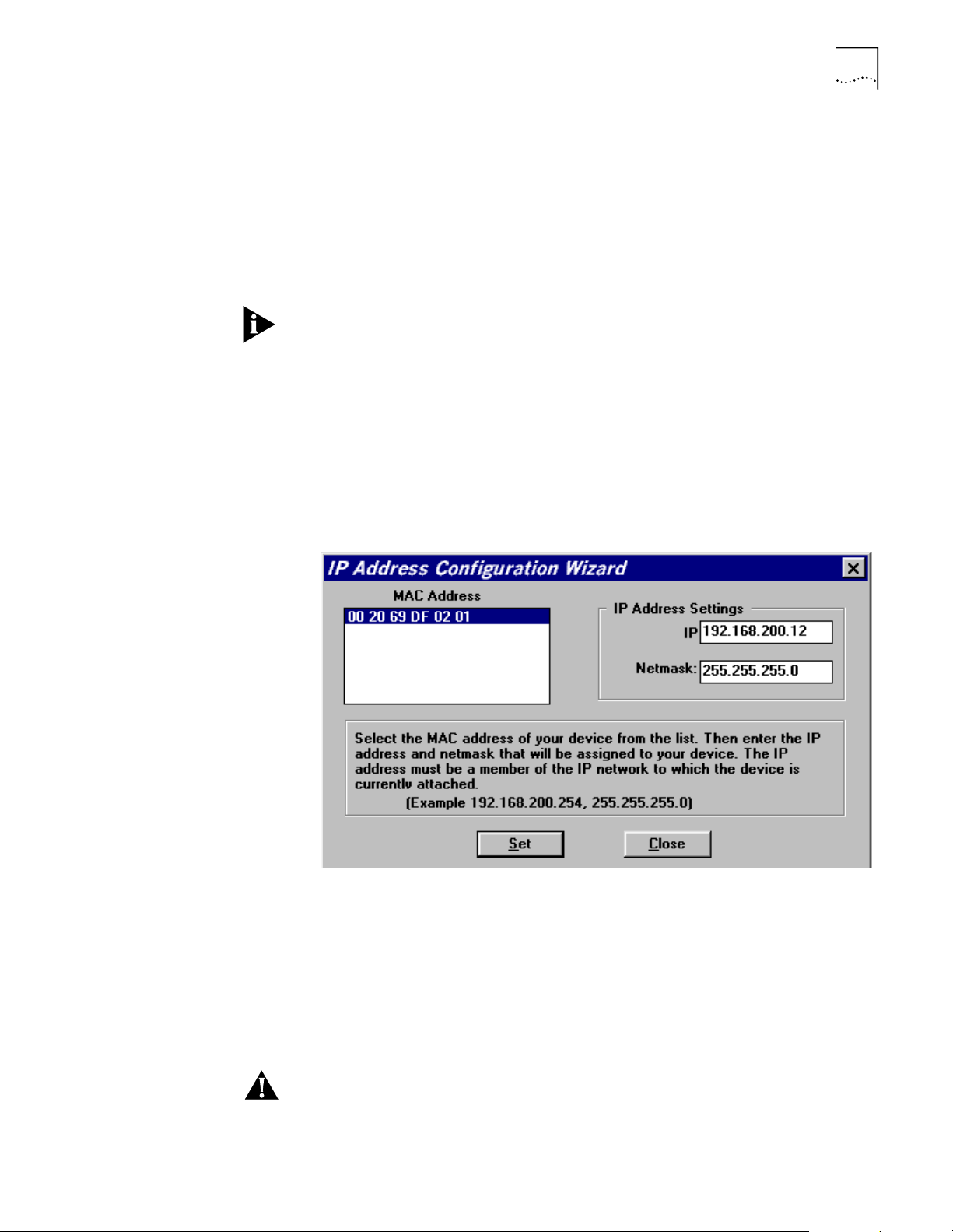
IP Wizard The IP Wizard is designed to help you assign a specific IP address to your unit.
In order to manage the 3Com HomeConnect ADSL Modem Ethernet, the unit
must be assigned an IP a ddress. You must also have an administrative l ogin pr o fil e
(user name and password) assigned.
To access the IP Wizard, go to Start > Pr ograms > 3Com HomeConnect ADSL
Modem Ethernet, and click on "IP Wizard".
IP Wizard will search the LAN for all unconfigured 3C om HomeConnect Modems.
As each unconfigur ed unit is found, the unit’s MAC address is placed in the
selection box. For mul tiple HomeConnect modems, you can determine which
MAC address belongs to the one you want to configure by disconnecting the
HomeConnect’s Ethernet cable and running IP Wizard a gain. The missing MAC
Address belongs to that unit.
Select which HomeConn ect Modem you want to configure and enter its LAN IP
address and netmask; then press Set.
If you assign the IP address with the IP Wizard, the administrative login name is
root and the password is !root. After you access the unit, you are strongly
advised to delete this login profile and create a new one with a secure
Page 22

3-6 CHAPTER 3: MANUAL SETUP
name and passwor d. (M aximum cha racter length of login name = 32, passwor d
maximum character length = 15.)
Configuring an IP
Network
The 3Com HomeConnect AD SL Modem Ethernet can have mor e than one IP
address (i.e., bel ong to mor e than one IP ne twork). To configure an IP addr ess use
the add ip network command. Each network has a network name. You will use
the network name when entering commands related to the network.
The CIDR-supporte d network address includes a local station address and subnet
mask using the format: nnn.nnn. nnn.nnn/A B C or 8-30. The first 4 octets describe
the IP address, followed by the subnet mask (contiguous) designator.
Y o u can speci fy the su bnet in o ne of two way s: a class or numeri cal desi gnation . If
you specify a Class C subnet mask, for instance, this command will generate a
255.255.255.0 sub net valu e for you. I f you spe cify the num ber of bits (to be set t o
1), the acceptable range is 8-30. The network address is invalid if the portion of
the station address not covered by the mask is 0.
Defining a numerical subnet is useful when your value falls in between classes.
Y o u can al so omit the mask altogether; it will automatically be calculated from the
address.
■ To add an IP network, use the command:
add ip network <network name>
address <ip address/mask>
frame [ETHERNET_II | SNAP]
■ To list the defined IP networks, use the command
list ip networks
Configuring Stat ic
Routes
■ By default, the network is enabled when it is created. You can disable the
network using the following command:
disable ip network <network name>
■ You can delete a disabled network using the command:
delete ip network <network name>
The reconfigure ip network command can be used to modify an existing IP
network’s address or frame type.
A Static route is a configured route that will remain in the IP routing table until
deleted.
■ To add a St atic route over the LAN, use the command:
add ip route <ip network address>
gateway <ip address>
metric <metric>
The route will appea r in the IP routing table. You can display all IP routes with the
list ip routes command.
To add a default route, use the command:
add ip default route
gateway <ip_address>
metric <metric>
Page 23

System Administration 3-7
The route will appear as destination 0.0.0.0 in the IP routing table.
■ To delet e an IP Static route, use the command:
delete ip route <ip network address>
Configuring DNS You can configure the 3Com HomeConnect ADSL Modem Ethernet to ac cess a
DNS server to resolve host names. This facility is used by the ping, telnet, rlogin
and update software ftp commands.
DNS server entries are stored in the DNS Serv er Table.
To add a DNS server use the command:
add dns server <domain_name>
primary <ip_addr>
secondary <ip_addr>
The <domain_name> parameter can be a specific domain (i.e., 3com.com) or it
can be the wildcard character ’*’, representing all domains. You can specify
different DNS servers for different domains. When searching for the appr opriate
DNS server, the modem first searches the local DNS server table for a entry for the
specific domain of the host name you are attempting to resolve. If no specific
entry is found, the wildcard entry is used.
IP Tools The 3Com HomeConnect ADSL Modem Ethernet CLI provides a stand ar d set of IP
System Administration
To list the entries in the DNS Server Table use the command:
list dns servers
To delet e an entry from the DNS Server Table use the command:
delete dns server <domain_name>
where domain name is the specific domain or the wildcard character ’*’.
utility prog rams including Ping, TELNET and RLOGIN.
This section provides details and examples for performing the following system
administration tasks:
■ Setting Date and Time
■ Setting System Identification
■ Configuring TELNET Login Access
■ Providing TFTP Access
■ Setting Password Protection
■ Configuration Scripting
Remember to save your configuration using the save all command before
rebooting your 3Com HomeC onn ect ADSL Mod em Ether net so that your changes
will be written to permanent FLASH memory.
Setting Date and Time Y ou can obtain the current date, time and system uptime using the command:
show date
Page 24

3-8 CHAPTER 3: MANUAL SETUP
The date and time information is provided in the following format:
System Date: 02-MAR-1998 05:17:00
System UpTime: 2d 08:37:54
You can set the date using the command: set date which sets the system date,
and leaves the time unchanged. The format is: dd-mmm-yyyy. The month should
be the first three characters of the month name. The year can be either 2 or 4
digits - 99 or 1999. Example: set date 01-JAN-1999
To set the t ime, use the command: set time which sets the system time, and
leaves the date unchanged. The format is: hh:mm:ss. The seconds (ss) field is
optional. Military time is used. For example, to set the time to 4:10 am enter the
command: set time 04:10 and to set the time to 4:10 pm enter the command:
set time 16:10.
Date and time settings are not maintaine d over a system reboot.
Setting Syst em
Identification
Configuring TEL N ET
Login Access
The system name, location and cont act in formatio n is usef ul when mo nitor ing the
3Com HomeConnect ADSL Modem Ethernet remotely. You should choose a
name, location and contact that is appropriate for the unit.
■ You can view the settings using the command:
show system
■ To set these pa rameters use the command:
set system name <name> location <location> contact <contact>
■ The name, location, and cont act can be up t o 32 charact ers long. For example,
set system name Modem1 location Rack4 contact SysAdmin@555-1212
Setting up a logi n use r al lo w s yo u to provi de controlled acce ss to the 3C o m
HomeConnect ADSL Modem Ethernet through TELNET. Connecting using TELNET
on a workstati o n al lo w s yo u to remotely manage the un it us i ng C L I.
A default user name of root and password !root are provided by the IP Wizard
during the initial installation. For secure access, you should add a private login
name and password and delete the default name.
■ To view the current login users, use the command:
list users
■ To add a login user, use the command:
add user <name> password <password>
The name can be up to 32 characters long and the password can be up to 15
characters long.
■ To delet e a login user, use the command:
delete user <name>
■ To change the password, use the command:
set user <name> password <new password>
■ To enable the use of CLI for TELNET users, issue the additional command:
enable security_option remote_user administration
Page 25

System Administration 3-9
Providing TFTP Access Trivial File Transfer Protocol (TFTP) provides a simple way to transfer files from one
machine to another. The 3Com HomeConnect ADSL Modem Ethernet has a TFTP
server that allows you to copy files to or from the unit. All you have to do is set up
TFTP access on the 3Com HomeConnect ADSL Modem Ethernet and run a TFTP
client program on a workstation.
You can configure the 3Com HomeConnect ADSL Modem Ethernet to provide
access to all TFTP clients or you can specify the IP addresses of the TFTP clients fo r
restricted access.
■ To view the current TFTP client access list, use the command:
list tftp clients
■ To add a TFTP client to the list, use the command:
add tftp client <host name or IP address or 0.0.0.0>
Provide either the host name or the IP address of the workstation running the TF TP
client. An address of 0.0.0.0 allows all TFTP clients unrestricted access.
■ To r emove a TFTP client from the list, use the command:
delete tftp client <host name or IP address or 0.0.0.0>
Setting Password
Protection
The 3Com HomeConnect ADSL Modem Ethernet provides the capability to
password-pr otect access to the CLI. When the password protection feature is
enabled, a user connecting to the CLI via the serial console port will be prompted
for the CLI password.
After the corr ect passwor d is enter ed, all CLI comman ds are accessible by the u ser.
The user can ’exit’ from the CLI to disable further access or can configure an idle
timeout period. If no commands ar e execu te d by the CLI fo r a period lo ng er than
the idle timeout period, the user will automatical ly be logged out of the console.
The password will have to be re-entere d in order to access the CLI again.
CLI password protection is disabled by default.
Password prot ection can be configured by the QuickSetup pr ogram or by using
CLI commands.
■ To enable or disable CLI password protection, use the commands:
set command login_required yes or
set command login_required no
■ To confi gure the login password, use the command:
set command password <
■ where <password> is an al phanumeri c string of 1 to 8 characters. The defau lt
password
>
password is "password."
Be sure to save your configuration after entering a new password.
■ After logging in to the CL I, you can exit the CLI with the command:
exit cli
■ To set the idle timeout peri od, use the command:
set command idle_timeout <timeout>
■ where <timeout> specifies the idle t imeout period in minutes.
By default, there is no idle timeout period.
Page 26

3-10 CHAPTER 3: MANUAL SETUP
Note: This capability is useful for system administrators or users who wish to
restrict access to the 3Com HomeConnect ADSL Modem Ethernet.
Care should be taken to remember the configured password. If the password is
forgotten, the unit must be sent back to 3C om sup p ort to have the fea tur e
disabled.
Configuration Scrip ting The 3Com HomeConnect ADSL Modem Ethernet provides a scripting utili ty that
will generate the CLI commands required to recreate a given configuration. After a
unit has been configured as desired, the command:
show configuration script
will generate the list of CLI commands to the console.
The console output can be captured into a file on your workstation using the
capabilities of your terminal emulation program or your TELNET utility. The
captured file can then be altered as required and then “played” into the console
of other unconfigured units.
As an alternative to directly executing a script file played into the console port, the
3Com HomeConnect ADSL Modem Ethernet is capable of executing a sequence
of commands from a script file stored in FLAS H memory. The file can be directly
created in FLASH memory using the capture text command, or it can be created
on a remote workstat ion and then transferred to FLASH memory using TFTP. To
create the file using the CLI, use the command:
capture text <filename>
After invoking the comma nd, any thing you t ype at th e console , anythi ng you typ e
at the console will be redirected to the specified file. To terminate input, type
Ctrl-D. After the text has been captured, you can execute the commands at any
time using the DO command as follows:
do <filename>
Page 27

FILTERING CAPABILITIES
4
Introduction The 3Com HomeConnect ADSL Mode m Ethernet pr ovides an exten sive set of dat a
filtering capabilities. For instance, filters can accept packets only from specific
addresses to provide added security, or filters can be added to reduce network
traffic and improve overall performance.
Packet filters control inter-network data transmission by accepting or rejecting the
passage of specific packets through network interfaces based on packet header
information. When data packets are recei v ed by a network interface such as an
Ethernet (LAN) or WAN port, a packet filter analyzes the packet information using
a set of rules you define. A filte r the n lets the packet pass through or disc a rds it.
This chapter contains information on the filtering capabilities for your 3Com
HomeConnect ADSL Modem Ethernet. It is divided into the following sections:
■ Filtering Overview
Filtering Capabilities of the 3Com HomeConnect ADSL Modem Ethernet
Filter Classes The 3Com HomeConnect ADSL Modem Ethernet supports the following filter
■ 3Com HomeConnect ADSL Modem Ethernet Filtering Capabilities
■ Creating Filters
■ Assigning Filters
■ Applying Filters
■ Managing Filters
The 3Com HomeConnect ADSL Modem Ethernet supports the following filtering
capabilities:
■ Input and output da ta filtering.
■ Source and destination address filtering.
■ Source and destination port filtering.
■ Established session filter ing. A packet filter can permit users to connect with a
remote network without letting remote users have access to the local network
(or vice versa).
classes:
■ Input data - filter packets as they enter.
■ Output da ta - filter packet s as they exit.
Filter Types Filters can be cla s sified by the followin g type s :
Page 28

4-2 CHAPTER 4: FILTERING CAPABILITIES
■ Data filters - based on protocol-specific packet information.
■ Generic filters - based on packet structure.
Data Filters Data filters control network access based on the protocol and source / destination
address of the packet.
Generic Filters Generic filters are protocol-independent and are specified by byte and offset
values in a packet. Packets are filtered by comparing each packet’s offset value
and byte information with the values that you define in the filter. The bridge will
accept or reject t he packet based on the result.
Creating generic filters can be a complex task. Only experienced users should
employ generic filters, and strictly in cases where data and advertising filters
cannot provide the f iltering capabilities that you require.
Creating Filters Before creating a filter file, you should carefully identify the information you want
to filter. Decide if you want a filter that discards packets (such as reject all packets
whose source MAC address is 002069000001) or accept only a subset of packets
(such as accept only bridged packets if the destination MAC address is
002069000001 or 002069000002). Also determine where you want to place the
filter . For example, figure out if you want to apply the filter to packets coming into
the Ethernet interface, to packets going out the WAN (ATM) interface, or to
packets coming from a specific port.
The first step in cr eating a filter on the 3Com HomeConnect ADSL Modem
Ethernet is to create a file using filter syntax. The file can be created using a text
editor on a remote workstation or it can be created using the CLI create text
command. File names should be short and descriptive, such as BLOCKPC1.FLT.
The create text command simply redirects console input into a text file in the
unit’s FLASH memory. It does not provide any editing capabilities.
If you create the file on a remote workstation, you will need to transfer the file to
the unit’s FLASH memory using TFTP.
Once the filter file has been created and stored in the unit’s FLASH memory, you
then use CLI commands to add the filter to the list of filters and apply the filter to
the appropri ate interface or bridge port profile.
Filter File Components You define the filtering rules used by the bridge within filter files. Filter files are
text files that are stored in the unit’s FLASH memory. You can create and modify
filter files using an off-line text editor, then TFTPing the finished file on to the unit.
To be valid, a filter file must always have the following file descriptor on the first
line: #filter
Be sure that no blank space precedes the descriptor, or an error will occur.
The file descriptor is followed by the bridge protocol section.
Protocol Sections/Bridge The following condi tions will generate errors or prevent normal filt er operation:
Page 29

Creating Filt ers 4-3
■ If you do not specify a protocol section in the filter file, no filtering will occur
and packets of that protocol type will be accepted.
■ If you specify a pr otocol se ctio n but do no t def ine any rule s, an err or wi ll occ ur.
To comment out the protocol section, you must place a pound (#) sign before the
section header and before all rules defined in the section.
Protocol Rules Protocol rules determine which p ackets may and may not acce ss the networ k. The
rule syntax is:
<line #> <verb> <keyword> <operator> <value>
The line # range is 1-998. This means you can comb ine up to 998 r ules to cr eate a
filter for a specific protocol. Additionally, line number 999 is used for the DENY
verb.
The combination of keyword, operator, and value forms the condition which
(when combined with the verb) determines whether a packet is accepted or
rejected.
When a packet is filtered, the bridge parses each rule defined in the protocol
section sequentially according to the line number. Filtering is performed based on
the first match that occurs. If there is no match, by default the packet is accepted.
For this reason, yo u should order your protocol rules so that the rules you expect
to be most frequently mat ched are in the beginning of the section. This reduces
the amount of parsing time that occurs during filtering. The following table
describes each field used in the rule syntax:
Table 4-1 Protocol Rules
Field Description
line # Each rule must have a unique line number from 1-998 plus 999 for the DENY
Verb This field can be one of the following:
Keyword The keywords for all protocol, descriptions, corresponding operators and values.
Operator Describes the relationship between the keyword and its value. The operator field
Value Contains an entity that is appropriate for the keyword.
verb. You must arrange rules in increasing orde r.
ACCEPT - Allow the packet access if the condition is met (use with DENY verb to
indicate reject all other packets).
REJECT - Do not allow the packet access if the condition is met.
AND - Logically use the AND condition with condition of the next rule to
determine if the pack et is a cce pte d or re je c ted . Both defined conditions m ust be
met.
must be one of the following:
= Equal
!= Not equal
> Greater than
< Less than
>= Greater or Equal
<= Less or Equal
=> Generic
Page 30

4-4 CHAPTER 4: FILTERING CAPABILITIES
The OR operation c an be implemented by successive rules. For example, to accept
a packet if the source address is x xx, or the destination address is yyy, the
following rules a r e use d :
BR-ETH:
1 ACCEPT src-addr=00-20-69-00-00-01;
2 ACCEPT dst-addr=00-20-69-00-00-02;
999 DENY;
The following table describes the keywords for the br idge protocol section and
their legal operators used in the rule syntax. (xx is a hex number).
Table 4-2 Protocol Keywords
ProtocolSection Keyword Operators Description and Value Range
BR-ETH src-addr
dst-addr
generic
=, !=
=, !=
=
Source MAC address (xx-xx-xx-xx-xx-xx)
Destination MAC address (xx-xx-x x-xx-xx-xx)
Generic filter
Generic Filter Rule The syntax for generic filters is slightly different than that for other protocol filters:
Step by Step Guide to
Creating Filter Files
<line #> <verb> GENERIC => ORIGIN = FRAME/OFFSET = <# of bytes>/
LENGTH = <# of bytes>/MASK = < 0x Mask>/VALUE = <0x value>
■ ORIGIN - The location in the packet to start the offset count. This is at byte 0
(FRAME).
■ OFFSET - The number of bytes from the origin to skip bef ore comparing the
value to the packet contents.
■ LENGTH - The number of bytes in the pa cket to compare to the value.
■ MASK - The mask to logically "and" with the packet contents before
comparing with the value (hex).
■ VALUE - The value (hex) to compare to the packet contents.
For example, a generic bridge filter to prevent all IP pack ets from being br idged is:
BR-ETH:
1 reject
generic=>origin=frame/offset=12/length=2/mask=0xFFFF/value=0x0800;
This section presents a step-by-step guide for creating and applying filters. These
steps assume that the filter file is created on a remote workstation and then
transferred to FLA SH memory using TFTP. If you use the CL I create text command
to create the filter file, you can omit steps 9 and 10.
To create a filter file:
1 Open a new text file. Enter the file descriptor on the firs t line: #filter
2 Enter the section header followed by a colon for the protocol rules you want to
define. For example: BR-ETH:
3 You can comment a section header out by placing a # sign before the section
header. This is us eful if you want t o inser t a pl aceh older for a pr ot o col sect io n you
Page 31

Assigning Filters 4-5
will define in the future. Also, use the # sign to add comments or what you expect
the filter to do for future reference.
4 Enter the rules you are defining. Observe the following guidelines.
■ Begin each rule with a un ique line number ranging from 1 - 998.
■ Arrange rules in increasing line number order within each protocol section.
■ Arrange rules so that the rules you expect to be matched most frequently are
toward th e top of the list
■ Delimit each rule with a semi-colon. Example :
BR-ETH 1 ACCEPT src-addr = 00-20-69-00-00-01;
2 ACCEPT src-addr = 00-20-69-00-00-02;
999 DENY;
5 Inspect the file to ensure that it meets all filtering rules.
6 This step is important since you cannot edit the filter file from within the CLI. T o
edit the file, you must modi fy it using a text editor, TF TP the modified file into the
FLASH (replacing the original file) and verify the filter using the verify filter
command.
7 Save the filter file using a .flt extension. The filter file extension will allow you to
differentiate the filter file from other files stored i n the bridge FLASH memory.
8 Y ou ca n use the li st files command to ensure the filter file was successfully store d
in the bridge FLASH memory.
9 Configure a PC as a Trivial File Transfer P rotocol (TFTP) client of the bridge by
entering add TFTP client <IP address>.
10 From a machine that has access t o th e same network as the bridge, use a TFTP
command to transfer the filter file to the bridge FLASH memory. For example,
from the workstation command line enter tftp <3Com HomeConnect ADSL
Modem Ethernet IP address> put <filter filename>
11 The bridge does not reco gnize a filter file stored in its FLASH memory until you
add it to the managed filter table. To notify the unit about the filter file for the first
time, you must issue the CLI command add filter <n ame> to add the filter to the
managed filter table. When the filter is added, the unit automatically verifies the
filter file syntax . If you m odifie d a f ile that had alr eady been a dded, use t he delete
filter <name> comman d to r em ove t he old fil e before TFTPin g the n ew fil e. Then
use the add filter <name> command again or TFTP the new file over the old one
and use the verify filter <name> command.
12 If the syntax is valid, no message is generated and the command prompt returns. If
the syntax is not valid, error messages are generated detailing the source of the
errors.
13 Apply the filter to the appropriate interface or port profile. After replacing a file,
you need to re-apply the filter for the new filter file to take effect.
For more details, refer to the next two sections. As s ig ning Filters discusses how
to decide where to apply a filter, and A pplying Filte rs explains the appropriate
CLI commands to use.
Assigning Filters Once a filter has been added to br idge’s list of managed filters, you can assi gn it to
the unit’s:
Page 32

4-6 CHAPTER 4: FILTERING CAPABILITIES
■ Interfaces
■ Ports
Interface Filters You can configure interface filters for any interface. Interface filters control access
to all networks available for both modem and non-modem interfaces. Yo u can
specify whether a filte r applies to packets entering the interface (input filter) or
leaving the interface (output filter). The br idge examines the filtering rules to
determine whether the interface accepts or rejects the packet.
Input Filter If an input filter is configured on an interface, all packets received into the bridge
in that interface are checked against the filtering rules before being forwarded to
another interface.
Output Filters If an output filter is configured on an int erface, all packet s receive d into the bridge
on that interface are checked against the filtering rules before exiting the bridge.
Input Filters vs. Output
Filters
When possible, use the input filter to filter an incoming packet rather than waiting
to catch a packet as it attempts to exit the bridge. This is recommended because:
■ A packet is prevented from entering the bridge, keeping potential intruders
from attacking the unit itself.
■ The bridging engine does not waste time processing a packet that is going to
be discarded anyway.
■ Most importantly, the bridge does not know which interface an outgoing
packet came in through. If a potential intruder forges a packet with a false
source address (in order to appear as a trusted host or network), there is no
way for an output filter to tell if that packet came in through the wrong
interface. An inp ut filter, on the other hand, can filter out packets purporting
to be from networks that are actually connected to a different interface.
Port Filters You can configure fil ters for a specific port profile that cont rols access to the
network for that location. This filter is only applied for the duration of the remote
network connection. As with interface filters, a port filter can be configured to
apply to input or output data tra ffic.
Applying Filters You can apply filters to interfaces and/or ports using the CLI. If you modify a file,
you need to re-apply it to make the changes take effect immediately. Otherwise
the changes will not take effect until the bridge network that the filter affects
goes down and comes back up . Thi s occu rs wh en a networ k is disab le d, the WAN
connection goes down then up, or when the 3Com HomeConnect ADSL Modem
Ethernet is reboot ed.
Apply a Filter to an
Interface
To configure an input or output filter on an interface, use the following CLI
commands:
set interface <interface name> input_filter <filter name>
set interface <interface name> output_filter <filter name>
Page 33

Managing Filters 4-7
Interface name is eth:1 for the Ethernet interface and atm:1 for the ATM
interface. For example, to appl y an inpu t filter to the ethernet interface :
set interface eth:1 input_filter filter.flt
When assigning the filter to the Ethernet interface, you must turn off filter access
by entering the CLI command set interface eth:1 filter_access off.
For more information about the filter access, refer to the Setting Filter Access section below.
Configuring a Filter for a
Port
■ To configure an input or output filter for a specific user, use the CLI
commands:
set port <port number>input_filter <filter_name>
set port <port number>output_filter <filter_name>
■ For example, to apply an output filter to port 2:
set port 2 output_filter filter.flt
Setting Filter Access When filters are assigned to both the WAN interfa c e and a port profile, you need
to tell the bridge which on e to use u sin g th e fi lter access p aramet e r. If filter access
is ON, the port filters will override interface filters. If filter access is OFF, then the
interface filters are used.
Always turn filter access OFF for the Ethernet interface sin c e th ere are no profiles
associated with it. If you do not turn if off, the filter will not be applied.
■ To set the filter access parameter to ON for a specific interface, use the CLI
command:
set interface <interface_name> filter_access ON
■ To set the filter access parameter to OFF for a specific interface, use the CLI
command:
set interface <interface_name> filter_access OFF
Managing Filters This section provides information about how to perform filter management tasks.
Displaying the Managed
Filter List
Adding Filters to the
Managed List
■ To display the list of managed filters, use the following command:
list filters <filter_name>
The resulting display might look like this:
Filter Name Status Protocols
filter.flt NORMAL BR-ETH
The add filter command verifies filter syntax prior to adding the filter to the
managed list. If the syntax is v alid, no message is generated and the command
prompt returns. If syntax errors exist, error messages ar e generated detailing the
cause of the errors.
Page 34

4-8 CHAPTER 4: FILTERING CAPABILITIES
If the syntax is invalid, the filter is still added to the managed list with a status of
verify failed. To correct filter file errors, you must make the changes to the original
filter file using a text editor, and re-TFTP the file to the bridge’s FLASH memory.
Then use the verify filter command to check the filter file syntax.
■ To add a filter file to the list of managed filters, use the CLI command
It may be helpful to use the list files command to see files successfully stored in
the FLASH memory.
add filter <filter name>
Removing a Filter from
an Interface
■ To r emove a filter that is assigned to an interface, use the fol lowing command:
set interface <interface name> input_filter ""
set interface <interface name> output_filter ""
The " " value represents a null value and removes the defined filter from the
interface. For exam ple, to remove an output filter from an interface named eth:1,
you would use the following command: set interface eth:1 output_filter ""
Removing a Filter from a
Port Profile
■ To r emove a filter that is assigned to a port profile, use the following
command:
set port <port number> input_filter ""
set port <port number> output_filter ""
The " " value represents a null value and removes the defined filter from the user
profile.
■ For example, to remove an input filter from port #2, you would use the CLI
command:
set port 2 input_filter ""
Deleting a Packet Filter ■ To delete a specific packet filter, removing the filter file permanently from the
FLASH memory, use the C L I command
delete filter <filter_name>
Verifying Filter File
Syntax
Showing Filter File
Contents
The verify filter command must be used if you make changes to a filter file tha t has
already been added t o the managed list and re-TFTP it back to the bridge’s FLASH
memory (using the same filename). The verify filter file will check the filter syntax.
If the syntax is valid, no message is generat ed and the command prom pt returns. If
the syntax is not valid, error messages are generated detailing the source of the
errors.
■ To veri fy a filter file, use the CLI command
verify filter <filter_name>
■ To view the contents of an entire filter file that has been added to the
managed list of filters, use this command:
show filter <filter_name>
Page 35

UPGRADING 3COM HOMECONNECT
5
ADSL MODEM ETHERNET
OPERATIONAL SOFTWARE
Introduction The 3Com HomeConnect ADSL Modem Et hernet operat ional sof twar e is stor e d in
the unit’s FLASH memory. There are two ways to update the operational software:
■ You can load new software through t he serial console port.
■ You can load new software using th e unit’s built-in FTP or TFTP client software.
Serial Port Update For serial port updating, there are three methods of obtaining the latest versions
of the 3Com HomeCo nnect ADSL M odem Ethernet Op erational S oftwar e. Choo se
the method that best suits you.
■ 3Com Instant Update Process - This is the preferre d method of obtaining the
operational software and documentation. Use the 3Com Instant Update to
check for the latest available version of the software, then download the
software.
■ 3Com FTP Site - Access the 3Com FTP Site to obtain software and
documentation
3Com Instant Update
Process
3Com FTP Site It is possible to obtain the latest 3Com HomeConnect ADSL Modem Ethernet
■ 3Com HomeConnect ADSL Modem Ethernet CD - Install from the CD if you
have the latest version of the software on CD.
If you have erased the opera tion al softwar e fr om your 3C om Ho meCo nnect ADSL
Modem Ethernet, you will need to reinstall the software from your CD.
If you have not yet installed Instant Update and configured it, you will need to do
so. The 3Com Instant Updat e is included on the 3Com HomeConnect ADSL
Modem Ethernet CD.
Open the Scheduling tab on the Instant Update Screen. Click Update Now.
Instant Update will prompt you to continue, and after you agree to this, it will
copy the new 3Com HomeConnect ADSL Modem Ethernet software to your hard
drive (to the default path of c:\Program File s\3Com\3Com HomeConnect
ADSL Modem Ethernet\Update).
You are now ready to install the 3Com HomeConnect ADSL Modem Ethernet
operational software to the unit. Continue to the Install Software via DOS
section.
operational software from the 3Com FTP site, without installing or running the
3Com Instant Update .
Launch your browser an d enter in the location of the 3C om FTP site
ftp.3com.com in your browser’s address or location field. You will then need to
Page 36

5-2 CHAPTER 5: U PGR ADING 3COM HOMECONNECT ADSL MODEM ETHERNET OPERATIONAL SOFTWARE
navigate through the directory structure to pub/xdsl/hceth. From this site, you
can obtain document updates from the DOCS subdirectory and code up dates
from the BINARIES subdirector y.
The code updates are stored in two forms in the BINARIES subdirectory. One form
is a self-extracting executable (with the extension .EXE) that contains the new
operational software along with the supplemental utilities required to load the
software into the unit via the serial port. The filename reflects the version of the
code (i.e., V010109.EXE would contain version 1.0.9).
The second form is simply the operational software itself. This can be used with
the Built-in Update procedure presented later in this chapter which directly loads
the software into the modem without storing the code on a PC. Files containing
the operational software only have the .NAC extension.
For serial port update, select the appropriate EXE file from the BINARIES directory
and store it to an empty subdirectory on your PC. You should execute the
self-extracting EXE to unzip the files to the local subdirectory. Continue to the
Installing Operational Software via DOS section.
3Com HomeConnec t
ADSL Modem Ethernet
CD
Installing Operational
Software via DOS
If you have obtained an updat ed 3Com HomeConn ect ADSL Modem CD, or if you
have erased the copy of the 3Com HomeConnect ADSL Modem Ethernet
Operational Software from your hard drive, you need to copy the operat ional
software from the CD to your hard drive.
1 Insert the 3Com HomeConnect ADSL Modem Ethernet Installation CD in your PC’ s
CD drive (for example, drive d:). An installation menu will be displayed.
2 Click Install the HomeConnect ADSL Modem Ethernet.
3 Follow the prompts on your screen to finish t he software install ation. In addition
to installing the 3Com HomeConnect ADSL Modem Ethernet operational
software, this will also install the utilities and printable documentation.
The 3Com HomeConnect AD SL Modem Ethernet operational software (the *.nac
file) included on the CD is copied to your ha rd drive and not the 3Com
HomeConnec t ADS L Mo d e m Ethernet unit. It is ins ta lle d to c:\Progr am
Files\3Com\3Com HomeConnect ADSL Modem Ethernet\Update.
Your 3Com HomeCon nect ADSL Modem Ethernet Installation CD installs a
DOS-based utility program onto your hard drive. This utility program, PCSDL.EXE,
is invoked by a DOS-batch file, DL.BAT, which has also been instal led to your drive.
In order to use PCSDL to load code to your 3Com HomeConnect ADSL Modem
Ethernet, use the console port straight-through console cable (provided) between
your workstation’s serial port and the unit’s console port.
To update the software from DOS, perform the following:
1 Using a terminal application such as HyperTerminal to test the serial connection,
set up the terminal application with the following settings:
9600 baud, No stop bits, 8-bit characters, no parity
2 Press Enter on your workstation. If the terminal application displays the '3com
homeconnect adsl modem ethe rnet>' prompt, the serial connection is
operational. You should now close the terminal applicati on (Hyperterminal).
Page 37

Update Using Built-in Update Software 5-3
3 Power off your 3Com HomeC onnect ADSL Modem Ethernet.
4 Open a DOS window on your workstation.
5 Change to the directory containing the new operational software. If you obtained
the software from the Installation CD or using Instant Update the default directory
is c:\Program Files\3Com\3Com HomeConnect ADSL Modem
Ethernet\Update.
The DL.BAT batch file uses the Com 1 port by default. You can change the port
used by editing the DL.BAT file. The relevant lines of the file are shown below.
REM
REM Edit the pcsdl command line -v parameter so that it includes
REM the REM v ersion num ber of the NAC file. Th e version number of
REM the NAC file is pa rt of t he file name . The file name sy ntax is:
REM
REM mdxxyyzzc where xx = major version number
REM yy = minor version number
REM zz = revision number
REM
REM Release 1.0.4 would have a filename of md010004.
REM
REM
REM Change the -p option on the pcsdl command line to use the
REM proper COM port.
pcsdl -p1 -r%BAUDRATE% -vNA1.0.4 -vSD0.3.3 -nSDmd -nNAmd
Update Using Buil t-i n Update Software
pcsdl -p1 -r%BAUDRATE% -vNA1.0.4 -vSD0.3.3 -nSDmd -nNA
Execute the batch file with the following command:
■ dl 115
6 When Establishing Comm unications... appears in your DOS window,
plug the 3Com HomeConnect ADSL Modem Ethernet back into the outlet.
7 Various st atus messages will be displayed, indicating the pr ogress of the
download. The download should take approximately 3 minutes to complete.
The update software FTP and update software TFTP commands allow you to
utilize the 3Com HomeConnect ADSL Modem Ethernet FTP or TFTP clients to
obtain and install the new op erational software. You can access these commands
directly from the serial console CLI session or through TELNET.
The 3Com HomeConnect ADSL Modem Ethernet must have an IP address
configured in order to use the built-in update commands. See the IP
Configuration section of Chapter 3 for informati on on configuring IP.
To update the software using the FTP command, use the CLI command:
update software ftp
<filename>
■ server <ip_addr or host_name>
■ path <path>
Page 38

5-4 CHAPTER 5: U PGR ADING 3COM HOMECONNECT ADSL MODEM ETHERNET OPERATIONAL SOFTWARE
■ username <us e rname>
■ password <password>
If you are obtaining the code update fro m the 3Com FTP site, you would use the
command:
update software ftp
<filename>
update software tftp
<filename>
■ server ftp.3com.com
■ path /pub/xdsl/hceth/binary
■ username anonymous
■ password <password>
where <filename> is the NAC file to load and <password> is your email address
(i.e., name@company.com). See the previous section 3Com FTP Site for more
information about files available fro m the 3COM FTP site.
To updat e the software using the TFTP command, use the CLI command:
■ server <ip_addr>
■ path <path>
Page 39

A
CLI Commands
CLI COMMAND DESCRIPTION
ADD Use the ADD command to define:
■ networks you will connect to
■ SNMP communities
■ users who can telnet to the unit
Note that some paramete rs have de fau lt val ues .
add bridge
access_mac_address
<mac_address>
add dns server
<domain_name>
add filter <filter name>
Adds a MAC Address to the Access MAC table. When the Access MAC feature is
enabled, only MAC Addresses in the Access MAC Table will be bridged.
Parameters Description
<mac_address > The MAC address being granted access.
primary_address [ip_address]
secondary_address [ip_address]
Adds the IP Address of a remote DNS Server for the specified Domain Name to the
Domain Name Server Table. The IP Host Name is first sent to the Primary Server to
be resolved. If t hat server cannot resolve the name, a reque st is sent to the
Secondary Server.
Parameters Description
<domain_name> Domain name. Use * for all domains.
primary_address The primar y IP address of the DNS server.
secondary_address The secondary IP address of the DNS server.
Parameters Description
<mac_address > The MAC address being granted access.
Adds a filter file na me to the filter table. The filter table is a ma naged list of filter
names used by SNMP. A filter file is a text file stored in the FLAS H file system, that
you load using TFTP. Add filter also verifies the syntax of the filter file . If syntax
verification fails, you’ll receive an error message, and the filter will still be added to
the table, but is not usable. You must correct the filter file in a text editor, use
Page 40

A-2 APPENDIX A: CLI COMMAND DESCRIPTION
TFTP to export the updat ed file to the system’s FLASH file system, and use the
verify filter command to check the filter’s syntax.
Parameters Description
<filter_name> Designation of a filter file, up to twenty ASCII characters.
add ip defaultroute
gateway <IP_address>
add ip network
<network_name>
{ metric [1] }
Defines a default gateway IP router, which acts as the default route for IP packets
destined for remote hosts.
Parameters Description
<IP_address > IP Address of the gateway router.
metric Integer representing how far away the default router is, in “hops” through
other routers. Values: 1-15.
address [ip_net_address]
frame [ETHERNET_II | SNAP | LOOPBACK]
{ interface [eth:1] }
{ enabled [yes] }
Adds an IP network to t he list of IP networks available over the specified interface.
Parameters Description
<network_name> Name of IP network, consisting of up to 32 un ique ASCII char acters; space
must be surrounded by double quotes.
address IP address of the network, in the format nnn.nnn.nnn.nnn, with or
without a mask specifier. The Ma sk S pe cifie r can b e ‘A’ , ‘B’, ‘C’, or ‘H’, or
a numeric value from 8 to 30 that de sc ribe s the n um ber of o ne bi ts in the
mask. If you do not specify a mask, the system will gener ate it for you
from the network address.
frame Frame encapsulation to be used on this IP network. The options are:
ETHERNET_II, LOOPBACK (for diagnostics), or SNAP.
interface Name of the interface which this IP network will communicate over. The
default is the first LAN interface (eth:1).
enabled This optional parameter indi cates whethe r the networ k is enabled (YE S) or
disabled (NO). YES is the default.
add ip route
<ip_net_address>
gateway [gateway_addr]
metric [hop_count]
Adds an entry to the IP routing table. IP packets destined for networks that match
this network will be routed to this address. The command list ip routes displays
your currently defined routes.
Parameters Description
<net_address> IP address of the remote network, in the format nnn.nnn.nnn.nnn, with or
without a mask specifier. The Mask Specifier can be ‘A’, ‘B’, ‘C’, or ‘H’, or a
numeric value from 8 to 30 that describes the number of one bits in the
mask. If you do not specify a mask, the system will generate it from the
network address.
gateway IP address of gateway used to reach this remote network.
metric An integer representing how far away the ro ute is, in “ho ps” throu gh other
routers. Values are 1-15.
Page 41

CLI Commands A-3
add snmp community
<community_name>
add snmp
trap_community
<name>
address [IP_address]
access [RO | RW]
Adds to the list of SNM P author ized users. The communit y name an d IP address of
SNMP requests fr om managers o n the network must match the list , which you can
see using list snmp communities.
Parameters De scr iption
<community_name> Group name that authorizes SNMP requests.
address IP address of the SNMP manager, in the form nnn.nnn.nnn.nnn
access Determines what type of access to SNMP MIBs the added user will
have. Options: Read Only (RO) and Read Write (RW).
address <IP_address>
Adds to the list of community name/IP address pairs that are allowed to receive
SNMP traps. You can see the list of authorized users with the list snmp
communities command.
Parameters Description
<name> Group name defining who can receive SNMP traps.
address IP address of the SNMP manager, in the form nnn.nnn.nnn.nnn
add syslog <ip_addr>
loglevel [loglevel]
add tftp client
<ip_addr>
add user [name]
password [password]
Adds an IP host to the list of IP hosts that will receive syslog entries. You can see
the current log levels for the system using list facilities, and modify the current log
level for each facility using set facility loglevel.
Parameters Description
<ip_address> IP address of the Unix host that will receive sys log information.
loglevel There are five levels of logging:
CRITICAL - a serious system error, which may effect sys tem
integrity
UNUSUAL - an abnormal event, which the system should be able
to recover from
COMMON - a regularly occurring event that is not frequent
VERBOSE - a regular periodic event, e.g. a routing update
message
DEBUG - for debugging only
Adds the tftp client to the authorization table for tftp access.
Parameters Description
<ip_addr> IP address of a host to be added. An address of 0.0.0.0 allows all
clients TFTP access.
{enabled [yes]}
Adds a Telnet user to the local user table. The list users command displays these
parameters for all users.
Parameters Description
Page 42

A-4 APPENDIX A: CLI COMMAND DESCRIPTION
Name Name of the user to be added, up to 32 ASCII characters.
Password User’s password, up to 15 ASCII characters.
Enabled This indicates whether the user is enabled. Enter YES or NO.
CAPTURE TEXT capture text <filename>
Redirects console input into a text file. Input redirection is terminated by Ctrl-D.
This command serves as a simpl e way to create filter files or to create command
scripts that can be executed using the DO command.
DELETE Delete commands remove anything you previously added.
delete bridge
access_mac_address
<mac_address>
Deletes a MAC Address to the Access MAC table. When the Access MAC feature
is enabled, only MAC Addresses in the Access MAC Table will be bridged.
Parameters Description
<mac_address > The MAC address being deni ed access.
delete configuration Deletes all your configuration files, reboots the system and restores system
configuration to default values.
delete dns server
<domain_name>
Removes the name server addresses associated with the specified domain from
the Domain Name Server Table.
delete file <file_name> Deletes a file from the FLASH file system. Use list files to see which files are
currently stored.
delete filter
<filter_name>
delete ip network
<network_name>
Removes the named filt er fr om the fi lter t able, an d del etes the f ile st ore d in FLASH
memory. Use list filters to see what filter files are in FLA SH memory.
Deletes an IP network from the interface that you specified when adding the
network. Use list ip net w ork s to see which networks are associated with which
interfaces. Always use disable ip network before deleting it.
delete ip route
<IP_address>
delete snmp
community <name>
delete snmp
trap_community
<name>
Deletes an IP addr ess fr om the IP rout ing table, t hat you pr eviousl y added with add
ip route. Deleting this route will cause IP packets destined for this network to use
the default route, which you can see using list ip routes. See add defaultroute
gateway to find out how to add a default route.
Deletes an SNMP community that was previously added with the add snmp
community command. You can use list snmp communities to see the curren t
entries.
Deletes an SNMP trap community name from the list of names and IP addresses
that are allowed to receive SNMP trap commands. You can use list snmp
communities to see the current entries.
Page 43

CLI Commands A-5
delete syslog
<ip_addr>
delete tftp client
<ip_addr>
Deletes the spec i fie d IP ad dres s from the lis t of a dd resse s wh ic h are auth orized to
receive syslog information. Use list syslog to see the currently allowed addresses.
Deletes the spec i fie d IP ad dres s from the lis t of a dd resse s wh ic h are auth orized to
TFTP. Use list tftp clients to see the currently allowed addresses.
delete user <name> Deletes a user you previo usly ad ded to the lo cal use r tabl e. Use li st use rs to see the
currently defined user, and show user to see the attributes you assigned to that
user using the add user or set user command.
DISABLE
disable bridge
access_mac_addresses
disable bridge
forwarding
disable bridge
spanning_tree
Disables the Access MAC feat ur e. When the A cce ss MAC fea t ur e is enab le d, on ly
MAC Addresses in the Access MAC Table will be bridged.
Globally disables bridging.
Disables use of the spanning tree. The span ning tree algorithm is required if there
is more than one bridge between the same two LAN segments.
disable ip network
<network_name>
disable link_traps
interface
<interface_name>
disable port <port
number>
disable security_option
snmp user_access
disable security_option
remote_user
administration
disable snmp
authentication traps
Disables the specified IP network. Make sure there is no activity on this network
before disabling it.
Prevents SNMP fr om se nding li nkup and lin kdown traps f or the spec ified i nterface .
You can see if the interface is currently enabled for traps by using the show
interface settings command.
Disables the specifie d bridge port from being used.
Turns off SNMP access to the CLI. This prevents remote users from using SNMP
and possibly damage the configu ratio n. You can use enable security_optio n snmp
user_access to re-enable full SNMP access.
Disables CLI access to remote TELNET users. All CLI configuration must be done
from the console port. You can use enable security_ option remote_user
administration to re-enable remote CLI access.
Instructs SNMP to not genera te a trap when an access is made usin g an unk nown
community.
disable user
<user_name>
Disables the specified user from being used. It also causes all active sessions
established using that particular user to terminate, and does not allow any new
sessions to occur using that user name. Disabli ng a user i s useful wh en pr ohib iting
a user’s access temporarily.
Page 44

A-6 APPENDIX A: CLI COMMAND DESCRIPTION
DO
do
Runs a script file that is stored in FLASH memory, which contains a series of CLI
<command_inputfile>
commands.
output [outputfile]
ENABLE
enable bridge
access_mac_addre sses
enable bridge
forwarding
enable bridge
spanning_tree
enable ip network
<network_name>
enable link_traps
interface
<interface_name>
enable port <port
number>
Enables the Access MAC feature. When the Access MAC fea ture is enabled, only
MAC Addresses in the Access MAC Table will be bridged.
Globally enables bridging.
Enables the spanning tr ee al gori thm for th e bridge connect ion. T he spann ing tr ee
algorithm is required if there is more than one bridge between the same two LAN
segments.
Enables the specified IP network, which you previously defined using add ip
network. Y ou can use list ip networks to see the currently defined IP networks, as
well as their current status.
This command tells SNMP to send linkup and linkdown traps for the specified
interface. Yo u can see if the interface is currently enabled for traps using the show
interface settings command.
Enables a bridge WAN port. The list port command displays a summar y of all
bridge ports.
enable security_option
remote_user
administration
enable security_option
snmp user_access
enable snmp
authentication traps
enable user <user
name>
exit CLI If CLI password protection is enabled, this command forces an immediate logout
Enables CLI access via TELNET. You can use disable security_optio n re mo te _ use r
administration to restrict CLI access to the console port only and enable
security_option remote_user administration to re-open full TELNET access.
Enables SNMP access to the user table. This allows remote users to use SNMP to
update the user table, and gain unauthorized access to the CLI. Use show
security_options to see the current security values.
This command tells SNMP to send a trap when access is made using an unknown
community.
Enables a TELNET profile. You must hav e previously added the profile using the
add user command. The list users command displays a summary of all configured
TELNET profiles .
from the CLI. The CLI password must be entered in order to access the CLI again.
Page 45

CLI Commands A-7
HELP
help <command> Provides information about possible commands and their formats. Typing help
alone lists the possible com mands. Typing help <command name> lists the
possible parameters for that command.
Typing part o f a keywo r d (comma nd or parameter ) a nd pr essin g Esc co mpletes the
keyword. If you have not yet entered enough of the keyword to be unique,
pressing Esc causes the bell to ring.
Typi ng ? after a command string displays the possible keywords and values for
that command.
HISTORY
history Displays your previous CLI commands. You can recall commands from th e history
using ^P ( C-P) to re call commands up the list, and ^N ( C-N) to r e call commands
working down the list. The default depth is 10 commands. You can modify the
history dept h using the set command history command.
idle timout <minutes> Sets the CLI inactivity timeout period. If the CLI is idle for the idle timeout period,
and if CLI password protection is enabled, the CLI password must be re-entered
before any commands can be executed.
LIST
list bridge
access_mac_addresses
list bridge forwarding Displays the forwarding and filtering information
Lists the contents of the the Access MAC Table. When the Access MAC feature is
enabled, only MAC Addresses in the Access MAC Table will be bridged.
MAC address - A unicast MAC address for which the bridge has forwarding
and/or filtering data
Status - One of:
other - not one of the following
invalid - aged out
learned - learned, and in use
self - statically defined, and in use
mgmt - unknown, but filtering information exists
RxPkt - Number of packets received from this MAC station
RxOctets - No. of bytes (octets) received from this MAC station
Page 46

A-8 APPENDIX A: CLI COMMAND DESCRIPTION
Fltr - Number of packets received from this MAC station that were fil tered out
(discarded)
Fwd - Number of packets received from this MAC station that were forwarded
TxPkt - Number of packets forwarded to this MAC station
TxOctets - Number of bytes forwarded to this MAC station
list connection events Displays the contents of the Connection Event Table. This table displays
informational and er ror messages re garding the establi shment of wide are
connections.
list dns servers Displays DNS Name Servers, which you configured using the add dns server
command. The domain name and the server address ar e listed for each DNS
server.
list facilities Displays the system facilities (processes) currently running, plus the default log
level. The log level is the severity of error that facility will pr oduce syslog entries
for. You can change the log level using the set facility loglevel command.
list filters Displays all the filter names in the filter table, which you previously defined using
the add filter command. You can remove filters using delete filter. The command
lists the filter file name, the status of the filter , and the protocols the file applies to.
For example:
Filter Name Status Protoc ols
easyfilter.fil NORMALBR BR-ETH
list files Displays the files currently stored in the FLASH file system. You can remove files
using delete file, but you can add them using TFTP only.
list interfaces Displays the installed interfaces, along with their operational status, administration
status, and interface index . If an interf ace is down, you can use enable interface to
try to bring it up. The command lists:
■ Index - number used to identify the inte rfaces po sit io n in the table
■ Name - interface name: eth:1 or atm:1
■ Oper Status - current, operating status of interfa ce; UP or DOW N
■ Admin Status - administr ative status you designated interface to be, up or
down. If it doesn’t match Oper Status, a pr oblem exists with the interface.
list ip addresses Displays the IP address for each interface. It lists:
■ Address - IP address of the interface
■ Bcast Algo - broadcast algorithm used
■ Reassembly Max Size - maximum allowable size of packet that can be
reassembled from a fragmented packet
Page 47

CLI Commands A-9
■ Interface - interface this IP address uses to connect to the system
list ip arp Displays the contents of the ARP cache. It lists:
■ IP Address - IP address for this entry
■ Phys Address - MAC address that the IP address maps to
■ Type - inte rfa c e type : E the rnet or Token Ring
■ If Name - eth:1, DA:1 or loopback
list ip netwo r k s Displays all the IP networks you previously defined using the add ip network
command. It also lists:
■ Name - network designation
■ Prot - always the IP protocol
■ Int - name of the interface this network runs on
■ State - state of the network; ENABLED or DISABLED
■ Type - STATIC or DYNAMIC network
list ip routes Displays all the statically defined IP routes that you previously defined using the
list ports Lists all bridge ports, showing:
list snmp communities
or list snmp
trap_communities
■ Network Address - address of the IP network
add ip route command. It lists:
■ Destination - IP address that the route resolves to
■ Prot - LOCAL
■ NextHop - address of the gateway used to reach this route
■ Metric - number of router hops away this route is from the system
■ If - interface that the route uses
■ Name - user desi gnation you specified using add vc
■ Network Ser v ic e - type of network service: e.g., RFC1483
■ VPI - Virtual Path Identifier
■ VCI - Virtual Channel Identifier
■ Status - link status: ACTIVE, INACTIVE or DISABLED
These commands display the defined SNMP communities, which you previously
defined using the a dd snmp co mmun ity co mmand. SNMP t rap_commu nities do es
not list access.
■ Community Name - community designation for the IP address
■ IP address - IP address of a member of the communi ty
■ Access (Read/Write) - type of access a member has to MIBs
Page 48

A-10 APPENDIX A: CLI COMMAND DESCRIPTION
list syslog Displays IP addresses which get syslog entries from the system. See add syslog for
more information, and delete syslog command to remove entries. This command
shows:
■ Syslog - IP address to which syslog entries will be sent
■ Log Level - reporting level of entries to send
■ Msg Count - curr ent number of messages sent since system bootup
Also see list facilities and set facilities commands, which let you view and change
log reporting levels for each system facility.
list tftp clients Displays IP addresses of all users who allowed to use the Trivial File Transfer
Protocol (TFTP) to connect to the system. Y ou must have used add netwo rk service
to add TFTP support to the system and used add tftp client to authorize users to
connect.
list users Lists all users, showing:
■ User Name - user designation you specified using add user
PAUSED COMMANDS
PING
ping
<ip_name_or_addr>
■ Login Service - The ser v ice used to login to the network (i.e. TELNET).
■ Status - link status: ACTIVE, INACTIVE or DISABLED
More (or CR) Continue printing
Quit Cancel rest of output
output [output_filename]
count [count]
interval [interval]
timeout [timeout_value]
Sends an ICMP echo r equest to a remote IP host. A reply from the pinged address
indicates success.
Parameters Description
<ip_name_or_address> IP address in dotted notation, or host name of remote system.
output A file name to direct output to.
count Number of IC MP echo request s to send.
interval Number of seconds to wait between sending each request.
timeout Number of seconds to wait for an echo response to return.
REBOOT Reboot the system. If you have made any configuration changes, be sure to save
all before rebooting. Also see the delete configuration command.
Page 49

RENAME
CLI Commands A-11
rename file
<input_file>
<output_file>
Renames files within the FLASH file system. The FLASH file system is a flat file
system (no subdirectories). Use the list files command to see what fil es currently
exist.
Parameters Description
<input_file> Name of the original file.
<output_file> New name for the file
reset ethernet counters Clears the statistics counters for the Ethernet port.
reset port <port
counters
number>
Clears the statistics counters for the specified bridge port.
SA VE
save all Saves all changes you have made during your session with the CLI. It i s a good idea
to save your changes frequently, just as you should with any type of editor.
SET
set adsl option
<optn_value>
Allows the setting of the ADI OPTN CMV. In order for the change to take effect, you must reset the ADSL chipset using the set adsl reset command.
set adsl power hi Sets the maximum power spectral density (PSD) value used by the Analog Devices
918 ADSL chipset to the re commended non-restricted value. This can be used to
get increased performance when connecting to newer ADI 918-based DSLAMS.
Use the show adsl config com mand to display the currently configured value.
The new PSD value takes effect on the next ADSL line retrain. To force a line
retrain, use the set adsl reset command.
set adsl power lo Sets the maximum power spectral density (PSD) value used by the Anal og Devices
918 ADSL chipset to the recommended r estri ct ed val ue. Th is is t he r e comme nde d
setting when connecting to older ADI 910-based DSLAMs. This is the default
setting. Use the show adsl config command to display the currently configu red
value. The new PSD value takes effect on the next ADSL line retrain. To force a
line retrain, use the set adsl reset command.
set adsl psdm
<psdm_value>
Sets the maximum power spectral density (PSD) used by the Analog Devices 918
ADSL chipset. This command can be us ed to restrict the output power. Use the
show adsl config command to display the currently configured value. The new
PSD value takes effect on the next ADSL line ret rain. To force a line retrain, use
the set adsl reset command.
set adsl reset Resets the ADSL interface.
Page 50

A-12 APPENDIX A: CLI COMMAND DESCRIPTION
set bridge aging_time <seconds>
Sets parameters for all bridge networks.
Parameters Description
aging_time Interval to wait before aging out MAC addresses that were learned from
forward_delay Interval bridge waits before bridging packets. This time is useful for the
spanning_tree_
priority
set command history <numerical range>
idle timout <minutes>
local_prompt <string>
forward_delay <seconds>
spanning_tree_priority <seconds>
other LAN segments. The default is 300.
bridge to listen to packets, look at the MAC addresses, and build its known
MAC address table. Default is 15 seconds.
Priority number det ermines w ho will be s een as the “ root” bridge in a bridg e
network. The default is 32768.
prompt <string>
login_required Enables or disables CLI password protection.
password The CLI pa s sw o rd. It mus t co n sis t of 1 to 8 al ph a nu m e r ic ( pr in table) characters,
inclusive.
Sets console parameters for CLI commands.
Parameters Description
history <numerical range> Sets the depth of the buffer holding the command history. Use the
history command to see the cu rrent de pth and a lis t of yo ur last CL I
commands. The default is 10 commands. Range: 1-500.
prompt <string> Sets the global command prompt for the CLI. Use show com
mand to see the currently defined prompt. Limit: 64 characters.
local_prompt <string> Sets a separate prompt for a command file process. Limit: 64
login_required [YES | NO] Set to YES if CLI console passwording is enabled.
password <alphanume ric
string>
characters.
The CLI password, up to 8 characters
set date <date> Sets the system date, and leaves the time unchanged. Use show date to see what
the current setti ngs are. The format is: dd- mmm-yyyy. The mont h should be the
first three c haracte rs o f t he mont h name . T he ye ar can be eith er 2 o r 4 di git s - 99
or 1999.
set facility
<facility_name>
loglevel [level]
Sets the severity reporting level for a facility . The hosts that will receive the error
log entries are defined using add syslog loglevel. Use list facilities to see what the
current loglevel is for each facility . The levels:
■ CRITICAL - a serious system error , which may effect system integrity
Page 51

CLI Commands A-13
■ UNUSUAL - an abnormal event, which the system should recover from
■ COMMON - a regularly occurring event that is not frequent
■ VERBOSE - a regular periodic event, e.g. a routing update message
■ DEBUG - for debugging purposes only
set interface
filter_access [ON | OFF]
<interface_name>
input_filter <filter_name>
output_filter <filter_name>
Sets filter parameters for the spec ified pr ot ocol on the speci fied in terface. You can
see the available filter files using list filters, view the contents of a filter file using
show filter, and add filter files to FLASH memory using TFTP.
Parameters Description
<interface_name> Designation of interface you are setting parameters for. Limit of 32
characters.
filter_access ON causes filters specified for an interface with a set interface co m m and,
input_filter Name of filter file you wis h to b e ap plied to the input stream coming in on
output_filter Name of the filter file you wish to be appl ied to the outpu t stream l eaving
to override filters specified with a set user command, when the filters are
of the same type.
the specified interface. Limit: 20 characters.
the specified interface. Limit: 20 characters.
set port <port number> pcr [number]
vci [number]
vpi [number]
description [filt er_ na m e]
input_filt er [f ilt er _ na m e]
output_filter [filter_name]
Specifies bridge port parameters.
Parameters Description
<port number> Port number (2..9)
input_filter Designation of the filter file in FLASH memory to be applied to the
output_filter Name of the filter file in FLASH memory to be applied to the out put
Pcr Peak Cell Rate (both UBR and VBR).
Vci Virtual Channel Identifier.
Vpi Virtual Path Identifier.
input data stream.
data stream.
Page 52

A-14 APPENDIX A: CLI COMMAND DESCRIPTION
set snmp community
<community_name>
set snmp
trap_community
<name>
address [IP_address]
access [RO | RW]
Modifies parameters for an SNMP authorized user. The community name and IP
address of SNMP requests from managers on the network must match the list,
which you can see using list snmp communities.
Parameters Description
<community_name> Group designation authorizing SNMP requests.
address IP address of the SNMP manager, in the form nnn.nnn.nnn.nnn
access Determines what type of access to SNMP MIBs the added user will have.
Options are Read Only (RO) and Read Write (RW).
address <IP_address>
Changes the IP address pairs that are allowed to receive SNMP traps. You can see
the list of authorized trap communities and addreses with the list snmp
trap_communities command.
Parameters Description
<name> Group name defining who can receive SNMP traps.
address IP address of the SNMP manager, in the form nnn.nnn.nnn.nnn
set system name [“name”]
set syslog <IP_address>
loglevel [level]
location [“location”]
contact [“contact info”]
Specifies system contact information, which is displayed using show system. The
user name is the remote account name. Location, name and contact names are
limited to 64 characters..
Parameters Description
name A name identifying the user to the system.
location The location of the user.
contact The information contact for the user.
Sets the error reporting level for syslog entries that will be sent to the specified IP
address. You must have previously defined this syslog IP address using add syslog.
There are f ive levels of logging:
■ CRITICAL - a serious system error , which may effect system integrity
■ UNUSUAL - an abnormal event, which the system should recover from
■ COMMON - a regularly occurring event that is not frequent
■ VERBOSE - a regular periodic event, e.g. a routing update message
■ DEBUG - for debugging only
Page 53

set time <time> Sets the system time, and leaves the date unchanged. Use sho w date to see what
the current settings are. The format is: hh:mm:ss. The seconds field is optional.
set user <user_name> message [“message”]
password [password]
session_timeout [seconds]
tcp_port [tcp_port]
terminal_type
Modifies user parameters.
Parameters Description
<user_name> Name of user, previous ly defined using a dd use r. Limit of 32 c ha r a cters.
message Message presented to a dial-in user.
password User’s password, up to 15 ASCII characters. Value is required.
session_timeout Interval before timing out a session.
tcp_port TCP Port number for the Telnet session.
Terminal_type The type of the terminal. This is an alphanumeric string, of up to 64
characters.
CLI Commands A-15
SHOW Show commands display details about system entities.
show adsl
configuration
show adsl performance Displays ADSL erro r stati stic s. Th e fol lo wing st atist ics an d cou nter s are collected in
Displays the current status of the command-line con figurable ADSL chipset items.
■ Option register - the OPTN CMV value to on the next reset of the ADI chipset.
■ PSDM config register - the ADSL maximum power spectral density setting.
15-minute interval bins:
■ Loss of framing err ors
■ Loss of power errors
■ Errored sec onds
■ Loss of signal errors
The statistics are displayed for the following time periods:
■ Current 15-minute interval
■ Previous 15-minute interval
■ Current day
■ Previous day
■ Total
Page 54

A-16 APPENDIX A: CLI COMMAND DESCRIPTION
show adsl statistics Displays block count statistics for the ADSL interface. It reports the number of
blocks transmitted and rec eived. It also r epo rts the numbe r of block s r eceived with
corrected errors, and the number received with uncorrectable errors.
show adsl
Displays the current status of the ADSL transceiver. It lists:
transceiver_status
■ Operational Mode – Current operational mode of the transceiver.
■ Attenuation – the difference in dB between transmitted and received signal
power.
■ Signal to Noise Ratio Margin – the SNR margin required by the transceiver
to maintain the ADSL link.
■ Transmit Power - The transmit power in dB of the local ADSL transceiver.
■ Code Word Length – The current code word size for the fast interlayed paths.
■ Downstream Rate – the negotiated bit rate for data received from the
network.
■ Upstream Rate – the negotiated bit rate for data transmitte d to the ne two rk.
show adsl version Displays version information about the ADSL interface. It lists:
■ Hardware Release Version - Version of the ADSL chipset present on the unit.
■ Firmware Release Version - Version of the ADSL firmware present on the
unit.
show atm status Displays current statistics for the ATM protocol running over the ADSL WAN
interface. It lists:
■ Cell Delineation - Whether or not cell delineation is currently achieved.
■ RX No Pkt Avail - Number of times a packet was reassembled but could not
be delivered over the LAN because of lack of packet memory within the
HomeConnect ADSL Modem .
■ RX Bad VPI or VCI - Number of ATM cells r eceived with a bad or inactive VPI
and/or VCI number.
show bridge settings Displays the settings for all bridge networks. Use set bridge to modify these values.
■ Base Aging Time - time to age out a known MA C address, default 300
■ Spanning Tree Forward Delay - delay after coming up before learning,
default is 15
■ Spanning Tree Priority - this bridge’s bid to be root bridge, default is 32768
■ Access MACs Only - This can be enabled or disabled.
■ Spanning Tree Mode - sets spanning tree algorithm on. Default is DISABLED
■ Base MAC Address - address of the bridge
■ Number of Networks - number of networks in this br idge
Page 55

show command ■ Displays the settings for Command History Depth, and the Current Prompt.
You can modify the history depth using set command history, and alter the
prompt using set command prompt. Prompts can hold a maximum of 64
characters. For example:
History Depth: 10
Current Prompt: 3COM-DSL>
Local Prompt: 3COM-DSL>
show crash_vector Displays debug information saved after a system crash.
show date Displays the system date, time, and uptime. For example:
System Date: 09-FEB-2107 15:06:10
System UpTime: 2d 08:37:54
show file <filename> Displays the contents of a text file.
CLI Commands A-17
show filter
<filter_name >
show ethernet
counters
protocol s [BR-ETH]
Displays the filter rules, based on the protocol options specified. The filter name
MUST be a filter file, as listed using list filters.
■ BR-ETH - Ethernet bridge data filter rules
■ BR-ETH - CALL - Ethernet bridge call filter rules
Displays counters for the ethernet interface.
INPUT COUNTE RS
■ Octets - bytes received
■ Ucast - Unicast packets received
■ MultiCast - Multicast packets received
■ BroadCast - broadcast packets received
■ Discards - Number of inbound packets which were chosen to be discarded
even though no errors had been detected to prevent their being deliverable to
a higher -layer p roto col. One possibl e reason f or discar ding such a packet could
be to free up buffer space.
■ Errors - For packet-oriented interfaces, the number of inbound packets that
contained errors preventing them from being deliverable to a higher-layer
protocol. For character-oriented or fixed-length interfaces, the number of
inbound transmission units that contained errors preventing them from being
deliverable to a number of inbound transmission units that contained
higher-layer protocol.
■ Unknown Prot - unknown protocol in packet
Page 56

A-18 APPENDIX A: CLI COMMAND DESCRIPTION
OUTPUT COUN TE RS
■ Octets - bytes transmitted
■ Ucast - unicast packets transmitted
■ MultiCast - multicast packets transmitted
■ Discards - Number of outbound packets which were chosen to be discarded
even though no errors had been detected to prevent the ir bei ng trans mitte d .
One possible reason for discarding such a pack et could be to free up buffer
space.
■ Errors - For packet-oriented interfaces, the number of outbound packets that
could not be transmitted because of errors. For character-oriented or
fixed-length inte rfa ce s, the nu m be r of ou tb ou n d tra nsm i s sio n un i ts tha t could
not be transmitted because of errors.
■ Out QLen - length of the output packet queue (in packets)
show ethernet settings Displays settings for the ethernet interface.
show ip settings Displays system wide IP information.
show memory Displays System RAM Memory usage.
show port <port
number> settings
show security_option
settings
■ IP System Host Address - IP address of the system
■ IP Forwarding – alw a ys D I SABLED
■ WAN to WAN Forwarding – indicates if forwarding between WAN Bridge
ports is allowed.
■ Total System Memory Resources - total amount of memory in system
■ Free Memory - amount of memory not in us e
■ Code Size - amount of memory used by code
■ Initialized Data Size, Uninitialized Data Size, Stack Size - static data areas
Displays the parameters defi ned for the specified VC. You can use list vc to see
which virtual cha n ne ls a re defined .
Displays status for SNMP User Access and Administration by Remote Users. You
can modify the SNMP User Access usi ng the enable or disable security_option
snmp commands. You can modify Administration by Remote User using the
enable or disable security_option remote_user commands.
■ SNMP User Access - ENABLED (default) or DISABLED
■ Administration by Remote User - ON or OFF
show snmp counters Displays many SNMP statistics.
INPUT COUNTERS
■ Packets - number of SNMP packets received
Page 57

CLI Commands A-19
■ Bad Versions - SNMP messages for an unsupported SNMP version
■ Bad Community Names - SNMP messages which used an unknown SNMP
community name
■ Bad Community Us es - SNMP messages which represented an SNMP
operation not allowed by the SNMP community nam ed in the message
■ ASN.1 Parse Errors - sum of ASN.1 or BER errors
■ Too Big Errors - SNMP PDUs for which t he value of the error-stat us field is
‘tooBig’
■ No Such Name Errors - SNMP PDUs where error-status field is ‘noSuchName’
■ Bad Value Errors - SNMP PDUs wher e error-status field is ‘badValue’
■ Read Only Errors - SNMP PDUs where the error-status field is ‘ readOnly’
■ General Errors - SNMP PDUs where the error-status field is ‘genErr’
■ Total Request MIB Objects - sum of MIB objects retrieved successful ly as the
result of receiving valid SNMP Get-Request and Get-Next PDUs
■ Total Set MIB Objects - sum of MIB objects altered successfully as the result
of receiving valid SNMP Set-Request PDUs
■ Get Request PDUs - sum of SNMP Get-Request PDUs accepted an d
processed
■ Get Next Request PDUs - sum of SNMP Get-Next PDUs accepted and
processed
■ Set Request PDUs - sum of SNMP Get-Next PDUs accepted and processed
■ Get Response PDUs - sum of SNMP Get-Response PDUs accepted and
processed
■ Trap PDUs - sum of SNMP T rap PDUs accepted and processed
OUTPUT COUNTERS
■ Packets - sum of SNMP packets transmitted
■ Too Big Errors - sum of SNMP PDUs generated by SNMP and for which the
value of the error-status field is `tooBig’
■ No Such Name Errors - sum of SNMP PDUs generated by SNMP and for
which the value of the error-status fi eld is `noSuchName'
■ Bad Va lu e Err ors - sum of SNMP PDUs generated by SNMP and for which the
value of the error-status field is `badValue'
■ General Errors - sum of SNMP PDUs generated by SNMP and for which the
value of the error-status field is `genErr'
■ Get Request PDUs - sum of SNMP Get-Request PDUs sent from SNMP
■ Get Next Request PDUs - sum of SNMP Get-Next PDUs sent from SNMP
■ Set Request PDUs - sum of SNMP Set- Request PDUs sent from SNMP
■ Get Response PDUs - sum of SNMP Get-Response PDUs from SNMP
■ Trap PDUs - sum of SNMP Trap PDUs sent from SNMP
Page 58

A-20 APPENDIX A: CLI COMMAND DESCRIPTION
show snmp settings Displays SNMP settings, which you can modif y using enable or disabl e snmp
authentication traps commands.
■ Authentication Traps - ENABLED (default) or DISABLED
show system Displays system information.
■ System Descriptor - for example:
3Com HomeConnect™ Remo te 810 V1 .0 .0 , Buil t on Oct 31 1996 at 11: 33 :05.
■ Object ID - identifies this system to SNMP managers
■ System UpTime - time the system has been running since last boot
■ System Contact - modify using set system
■ System Name - modify using set system
■ System Location - modify using set system
■ System Services - for example, Internet End To End Applications
■ System Version - loaded version of the system software
show user <name>
settings
TELNET TELNET commands are available to users who dial in, and whose type is network
telnet
<ip_name_or_addr>
telnet <ip_addr>
TCP_port <number>
UPDATE The Update Software FTP and Update Software TFTP commands allow you to
Displays the parameters defi ned for the specified TELNET user. You can use list
users to see which users ar e defined.
(type parameter in add user), whose host_type is prompt (host_type parameter in
set login user), and whose logi n_servic e is TELNET (login_service parameter in set
login user).
Establishes a TELNET client session with the specified IP address.
Establishes a TELNET cl ient sessi on wit h the sp ecified I P add ress using the spec ified
TCP port number. It works just like the TELNET command, except you also specify
the TCP port number to be used. The default TCP port number is 23.
utilize the 3Com HomeCo nnect ADSL Modem Ethernet FTP or TFTP clients to
obtain and install the new operational software. You can acce ss these commands
directly from the serial console CLI se ssion or through TELN ET.
To updat e the software using the FTP command, use the C L I command:
update software ftp
<filename>
server <ip_addr>
path <path>
username <us e rname>
password <password>
To updat e the software using the TFTP command, use the CLI command:
Page 59

TELNET Commands A-21
update software tftp
<filename>
VERIFY
verify filter
<filter_name>
TELNET Commands
send <string> Transmits a TELNET control character. Be sure the parameters are upper case. The
server <ip_addr>
path <path>
Verifies the syntax of a filter file, which has been previously added to the table. If
you update a filter file and TFTP it to the FLASH file system, and the file already
exists in the filter table, then you use this command to verify the files syntax. You
can use list filters to see which files are currently in the filter file table, and what
the status of each is.
The following commands are available to TELNET users. They are accessed by
pressing control - ].
close Closes the active TELNET connection.
help Lists the available commands
choices are:
Parameters Description
AYT Are you there
IP Interrupt process
BRK Break
AO abort output
EC erase character
EL erase line
GA go ahead
NOP no - operation
EOR end of record
SYNC synch
set_escape <string> Allows changing the TELNET escape character from ^] to something else. Control
characters are specified using the carat character followed by another character.
For example, to set the TELNET escape character to control - X, type set_escape
^X.
status Displays the IP address of the remote host and the value of the TELNET escape
character.
CLI Exit Commands
These commands are availab le to TELNET users so they can disconnect from the
CLI.
Bye, Exit, Leave, Quit Leave the CLI, but keep this connection open. This command returns you to the
TELNET commands.
Page 60

A-22 APPENDIX A: CLI COMMAND DESCRIPTION
Logout Leave the CLI and close this connection. This ends the TELNET session.
Command Features
The command language has several built in features that make it easier to use.
When abbreviating commands, it is sometimes hard to remember the commands
and their syntax. Using command completion and positional help aids in jogging
your memory of the commands and their parameters while you are typing in a
command string.
Command Retrieval Command retrieval retrieves commands from the history of previous commands
entered. You can display the current command history using the history
command. You can c hange the number of commands kept in the command
history buffer using the set command history command.
^p recall the previous command in the history list
^n recall the next command in the history list
Positional Help Positional help displays the list of possible parameters when you type ? after any
command or parameter . It then redisplays the line you typed, without the ?, so
you can enter the paramete r you wish to use. This helps you find the parameter
you need, and add it to your command, without having to retype the entire
command string. Be sure to leave a space between the keyword and the question
mark to use positional help.
Command
Completion
The escape key provi des comman d comp le tion . If you press the escape key befor e
you finish typin g a command or par ameter, the rest of the c ommand or paramet er
will be displayed (complet ed), and you can continu e enteri ng the command . If the
command or parameter is ambiguous, the bell will ding, and the display will not
change.
Output Pause The output will pause when there is more than 24 lines of output. Type ‘more’ (or
press CR) to continue, or ‘quit’ to stop.
Command Kill To d isco nti nue the cu rr en t comma nd act ion, and f lus h any co mman ds whi ch have
been typed ahead , us e ^C (c on trol -C) .
Comments
Nothing following a semicolon will be processed. This is useful when you are writing CLI
script files. The do command runs a CLI script.
Page 61

A
Add command 2-2
ADSL
reset A-11
show settings A-16
show transceiver_status A-15
show version A-16
ATM
show status A-16
ATM Information, configuring 3-2
B
Bridge Networks
Configuration
enable bridge spanning_tree A-6
set bridge A-12
Statistics
list bridge forwarding A-7
bridge Networks
Configuration
disable bridge spanning_ tree A-5
show bridge settings A-16
Managing
disable bridge network A-5
Bridging
Advanced 3-3
Overview 3-1
C
CLI Conventions and Terminology 2-1
CLI help 2-2
CLI, abbreviation 2-2
CLI, control characters 2-2
CLI, names,strings 2-1
Command Line Interface (CLI 2-2
Configuration 2-2
Configuration Overview 3-1
Console 1-1
D
Date 3-7
Diagnostics
PING A-10
DNS
Configuration
add DNS server A-1
delete DNS server A-4
list DNS servers A-8
Page 62

F
Filtering Capabilities 4-1
Filters
add filter A-1
delete filter A-4
list filters A-8
FLASH ROM 2-2
I
Interface 1-1
Interfaces
disable link_traps interface A-5
list interfaces A-8
Interne t, viewing Web resources 1-1
IP
Configuration
add ip network A-2
delete ip network A-4
disable ip network A-5
enable ip network A-6
list ip networks A-9
Diagnostics
list ip ARP A-9
Routing
add ip defaultroute gateway A-1, A-2, A-4, A-5, A-6, A-7, A-8
add ip route A-2
delete ip route A-4
list ip routes A-9
Overview 3-5
Statistics
show ip settings A-18
TF TP
add tftp client A-3
delete tftp client A-5
list tftp clients A-10
IP Routing, Framed Routes 3-6
IP Routing, Static Routes 3-6
IP Wizard 3-5
L
List command 2-2
M
Messages
add syslog A-3
list syslog A-10
Page 63

N
Network user 2-2
P
Package, what’ s included 1-1
Password 2-2
Password Protection 3-9
Passwords
add user A-3
PC 1-1
R
Remote Site Management 3-1
S
Scripts
CLI
do (run CLI script) A-6
Security
CLI Access
disable security_option remote_user administration A-5
enable security_option remote_user administration A-6
Dial-in
disable user A-5
enable user A-6
Virtual Channel
disable VC A-5
enable VC A-6
Set command 2-1, 2-2
SNMP
add snmp community A-3
add snmp trap_community A-3, A-14
delete snmp community A-4
delete snmp trap_community A-4
disable link_traps interface A-5
disable security_option snmp user_access A-5
disable snmp authentication traps A-5
enable link_traps interface A-6
enable security_option snmp user_access A-6
enable snmp authentication traps A-6
list snmp communities A-9
System Administration
Overview 3-7
System Commands
delete configuration A-4
delete file A-4
delete syslog A-5
do (run a script file) A-6
Page 64

help A-7
history A-7
list facilities A-8
list files A-8
reboot A-10
rename file A-11
System ID 3-8
T
TELNET access 3-8
TFTP access 3-9
Time 3-7
U
Users
delete user A-5
show user settings A-20
show vc settings A-18
V
VC
set vc A-13
Virtual Channel (VC) 2-3
W
Web Browser access 3-8
Page 65

TECHNICAL SUPPORT AND LIMITED WARRANTY
Notice: This modem was not designed or approved for use in
Europe, Australia, or New Zealand.
Technical Support 3Com provides easy access to techn ic a l sup p ort in fo rm ation through a
variety of services. This section describes those services.
Technical Support
Hotline
Online Technical
Support
If you need to Return
the Modem to Us
Technical questions about the 3Com HomeConnect ADSL Modem
products can be answered by technical suppo rt representatives. This
hotline is a toll call.
847-262-3700
8:00am - 6:00pm CST; Monday through Friday
Canadian customers can speak to a technical support representative by
contacting Keating Technologies.
905-305-6570
8:00am - 8:00pm EST ; Monday through Friday
3Com offers product support 24 hours a da y, 7 days a week, through:
World Wide Web consumer.3com.com/support
3Com BBS 847-262-6000
Email support@consumer.3com.com
Contact 3Com Custome r Supp o rt. If the supp ort representative
determines that you need to return the modem, you will receive an SRO
(Service Repair Order) number. You must have an SRO number before
returning the modem to us. Ship the unit, postage paid, in a strong box
made of corrugated cardboard with plenty of packing material. DO NOT
Page 66

send the modem back in the original box. Send ONLY the modem (NOT
manuals, diskettes, e tc.) Inclu de your SRO numb er, name and address on
the shipping labe l as wel l as inside the package . If poss ib le , se nd the
package via a courier capable of tracking the progress of the shipment.
Ship to the following address:
3Com
ATTN: PCD RMA
[your SRO #]
1800 W. Centra l Avenue
Mount Prospect, IL 60056
Customers in Canada needing to return a modem for repair or
replacement should send the modem to the following address:
Keating Technologies
25 Royal Crest Court
Suite 120
Markham, ONT L3R 9X4
Manufacturer’s Declaratio n of Conformity
Caution to the User The user is cautioned that any changes or modifications not expressly
3Com Corporatio n
3800 Golf Road
Rolling Meadows, IL 60008
U.S.A.
declares that this product conforms to the FCC’s specifications:
Part 15:
Operation is subject to the following two conditions:
(1) this device may not cause harmful electromagnetic interference, and
(2) this device must accept any interference received including
interference that may cause undesired operations.
This equipment uses the following USOC jacks: RJ-11C.
approved by the party responsible for compliance could void the user ’s
authority to operate the equipment.
Part 68:
Page 67

This equipment complies with FCC Rules Part 68. Located on the bottom
of the modem is the FCC Registration Number and Ringer Equivalenc e
Number (REN). You must provide this informatio n to th e te le ph o ne
company if requested.
The REN is used to determine the n umber of devices you may legally
connect to your telephone line. In most areas, the sum of the REN of all
devices connected to one line must not exceed five (5.0). You should
contact your telephone company to determine the maximum REN for
your calling area.
This equipment uses the following USOC jacks: RJ11C.
This equipment may not be used on coin service provi ded by the
telephone company. Connection to party lines is subject to state tariffs.
An FCC compliant telephone cord and modular plug are provided with
this equipment, which is designed to connect to the telephone network
or premises wiring using a Part 68 compliant compatible jack. See
installation in structions for details.
If you have an external modem:
UL Listing/CSA Certified
This information technology equipment is UL-Listed and CSA-Certified for
the uses described in the users guide.
If you have an internal modem:
UL Listing/CUL Listing
This information technology equipment is UL-Listed and CUL-Listed for
use with UL-Listed personal computers that have installation instructions
detailing user ins ta ll ation of card accessories .
Fax Branding The Telephone Consumer Protection Act of 1991 makes it unlawful for
any person to use a computer or other electronic device, including fax
machines, to send any message unless such message clearly contains in
the margin at the top or bottom of each transmitted page or on the first
page of the transmission, the date and time it is sent, an identification of
the business or ot her e ntity, or other individual se nding the me ssage, and
Page 68

the telephone numb er of t he sendin g mac hi ne or of such busi ness, o t her
entity, or individual. (The telephone number provided may not be a 90 0
number or any other number for which charges exceed local or
long-distance transmission charges.)
In order to program this information into your modem, refer to the
RapidComm manual on the CD-ROM that shipped with your modem. If
you are using a different commu nication softwar e program, refer to its
manual.
Radio and Television Interference
This equipment generates and uses radio frequency energy and if not
installed and used properly, in strict accordance with the manufacturer’s
instructions, may cause interference to radio and television reception. The
modem has been teste d and foun d to co mply wit h the l imits f or a Class B
computing device in ac cor d ance wit h the spec ifi cat ions i n Part 15 of FCC
rules, which are designed to provide reasonable protection against such
interfer ence in a residential installation. This equipment generates, uses
and can radiate radio frequency energy and, if not installed and used in
accordance with the instructions, may cause interference to radio and
television communications.
However, there is no guarantee that interference will not occur in a
particular installation. If this device does cause interference to radio or
television reception, which you can determine by monitoring reception
when the modem is install ed and whe n it is r emo ved from the computer,
try to correct the problem with one or more of the following measures:
· Reorient the receiving antenna (for televisions with antenna reception
only) or cable in p ut de v ic e .
· Relocate the computer with respect to the receiver.
· Relocate the computer and/or the recei ver so that they ar e on separate
branch circuits.
If necessary, consult your dealer or an experienced radio/television
technician for additional suggestions. You may find the following
booklet, pre pared by the Federal Communications Commission, helpful:
How to Identify and Resolve Radio-TV Interference Problems
Page 69

Stock No. 004-000-0345-4
U.S. Government Printing Office
Washington, DC 20402
In accordance with Part 15 of the FCC rules, the user is cautioned that
any changes or modifications to the equipment described in this manual
that are not expressly appr oved by 3Com could void t he user’s authority
to operate the equipment.
For Canadian Modem Users
Industry Canada (IC) This digital appa ratus does not exceed the Class B limits for radio noise
emissions from digital apparatus set out in the interference-causing
equipment standard entitled Digital Apparatus, ICES-003 of Industry
Canada.
NOTICE: The Ringer Equ ivale nce Number (R EN) assigned to each termi nal
device provides an indication of the maximum number of terminals
allowed to be connected to a telephone interface. The termination on an
interface may consist of any combination of devices subject only to the
requirement that the sum of the Ringer Equivalence Numbers of all
devices does not exceed 5.
The Ringer Equivalence Number is located on the bottom of the modem.
Notice The Industry Canada (IC) label identifies certified equipment. This
certification means the equipment meets certain telecommunications
network protective, operational, and safety requirements as prescribed in
the appropr iate Terminal Equipment Technical Requirements docum ent(s).
The Department does not guarantee the equipment will operate to the
user’s satisfaction.
Before instal li ng t his equi pmen t, u ser s sh ould ensure that it i s per mi ssible
to be connected to the facilities of the local telecommunications
company. The equipment must also be installed using an acceptable
method of connection. In some cases, the company’s inside wiring
associated with a single-line, individual servi c e may be extended by
means of a certified connector assembly (telephone ext ension cord.) The
customer should be aware that compliance with the ab ove conditions
may not prevent degradation of service in some situations. Currently,
Page 70

telecommunication companies do not allow users to connect their
equipment to jacks except in precise situations that are spelle d out in
tariffing arrangements with those companies.
Repairs to certified equipment should be coordinated by a representative
designated by the suppli er. Any repairs or alter ati ons mad e by t he user to
this equipment, or equipment malfunctions, may give the
telecommunication s company cause to r equest t he user t o disconnec t the
equipment.
For your own protection, make sure that the electrical ground
connections of the power utility, telephone lines, and internal metal lic
water pipe system, if present, are connect ed together. This precaution
may be particularly important in rural areas.
CAUTION: Do NOT att empt to mak e such connect ions yo ursel f. Instead ,
contact an electric inspection authority or electrician, as appropriate.
«AVIS : L'étiquette d' In du s tri e Ca na d a ide nt ifie le ma té r ie l ho m ol og u é. Cette
étiquette certif ie que le matériel est conforme aux normes de protection,
d'exploitation et de sécu rité des réseaux de télécommunicati ons, comme
le prescrivent les doc uments concernant les exigences technique s relatives
au matériel terminal. Le Ministère n'assure toutefois pas que le matériel
fonctionnera à la satisfaction de l'utilisateur.
Avant d'installer ce matériel, l'utilisateur doit s'assurer qu'il est permis de
le raccorder aux installations de l'entreprise locale de télécommunication.
Le matériel doit égal ement êt re i nstallé en suivan t une méthod e acceptée
de raccordeme nt. L'abonné ne doit pas oublier qu'il est possible que la
conformité aux conditions énoncées cidessus n'empêche pas la
dégradation du service dans certaines situations.
Les réparations de matériel homologué doivent être coordonnées par un
représentant désigné par le fournisseur. L'entreprise de
télécommunications peut demander à l'utilisateur de débrancher un
appareil à la suit e de réparations ou de modifications effect uées par
l'utilisateur ou à cause de mauvais fonctionnement.
Pour sa propre protection, l'utilisateur doit s'assurer que tous les fils de
mise à la terre de la source d'énergie él ectriq ue, de s li gne s
et des canalisations d'eau métalliques, s'il y en a, sont raccordés
téléphoniques
Page 71

ensemble. Cette précaution est particulièrement importante dans les
régions rurales.
Avertissement: L'utilisateur ne doit pas tenter de faire ces
raccordements lui même; il doit avoir recours à un service d'inspection
des installations électriques, ou à un électricien, selon le cas.
Centre de guarantie et de service après-vent e:
Keating Technologies
25 Royal Crest Court, Suite 120
Markham, ONT L3R 9X4
3Com Corporation Limited Warranty
YEAR 2000
WARRANTY
3Com warrants this hardware product to be free from defects in
workmanship and materials, under normal use and service, for the
lifetime of the product from the date of purchase from 3Com or its
authorized reseller. 3Com’s sole obligation under this express warranty
shall be, at 3Com’s option and expense, to repair the defective product or
part, deliver to Customer an equivalent product or part to replace the
defective item, or if neither of the two foregoing options is reasonably
available, 3Com may, in its sole discretion, refund to Customer the
purchase pric e paid for the defective product. All products that are
replaced will become the property of 3Com. Replacement products may
be new or reconditioned. 3Com warrants any replaced or repaired
product or part for ninety (90) days from shipment, or the remainder of
the initial warranty period, whichever is longer.
In addition to the Warranty stated above, 3Com warran ts tha t each
product sold or lice nsed to Cust omer on a nd af ter Janu ary 1, 1 998 that i s
date sensitive will continue performing properly with regard to such date
data on and after January 1, 2000, provided that all other products used
by Customer in connection or combination with the 3Com product,
including hardware, software, and firmware, accurately exchange date
data with the 3Com product, with the exception of those products
identified at 3Com’s Web site,
http://www.3com.com/products/yr2000.html
as not meeting this standard. If it appears that any product that is stat ed
to meet this standa rd does no t per form pr op erly with r egar d to such da te
data on and after January 1, 2000, and Customer notifies 3Com before
Page 72

the later of Ap ril 1, 2000, or ninety (90) days after purchase of the
product from 3Com or its author iz e d reselle r, 3Com shall, at its option
and expense, provide a software update which would effect the proper
performance of such product, repair such product, deliver to Customer
an equivalent produc t to replac e suc h produc t, or if no n e of the
foregoing is feasi ble, ref und to Customer the pur chase price pa id for such
product.
Any software upd ate or replaced or repaired product will carry a Year
2000 Warranty for ninety (90) days after pur chase or until April 1, 2000,
whichever is later.
Obtaining Warranty
Service
Customer must contact a 3Com Corporate Service Center or an
Authorized 3Com Service Center within the applicable warranty period to
obtain warranty service authorizati on . Da ted proof of pu rchase from
3Com or its authoriz e d reselle r m ay be required. Produc ts retur ned to
3Com’s Corporate Service Center must be pre-authorized by 3Com with
a Service Repair Order (SRO) number marked on the outside of the
package, and sent pr epaid and packa ged approp riately for safe shipment,
and it is recommended that they be insured or sent by a method that
provides for tracking of the package. The repaired or repl aced item will
be shipped to Customer, at 3Com’s expense , no t lat er than thir ty (30 )
days after 3Com receives the defective product. Return the product to:
In The United States:
3Com
USO# ______________
Attn. Dock 15 PCD
1800 W. Centra l Ave.
Mt. Prospect, IL 60056
In Canada:
Keating Technologies
25 Royal Crest Court, Suite 120
Markham, ONT L3R 9X4
3Com shall not be responsible for any software, firmware, information,
or memory data of Customer contained in, stored on, or integrated with
any products returned to 3Com for repair, whether under warranty or
not.
Page 73

Warranties exclusive IF A 3COM PRODUCT DOES NOT OPERATE AS WARRANTED ABOVE,
CUSTOMER’S SOLE REMEDY FOR BREACH OF THAT WARRANTY SHALL
BE REPAIR, REPLACEMENT, OR REFUND OF THE PURCHASE PRIC E PAID,
AT 3COM’S OPTION. TO THE FULL EXTENT ALLOWED BY LAW, THE
FOREGOING WARRANTIES AND REMEDIES A RE EXCLUSIVE AND ARE IN
LIEU OF ALL OTHER W ARRANTIE S, TERMS, OR CONDITIONS, EXPRE SS OR
IMPLIED, EITHER IN FACT OR BY OPERATION OF LAW, STATUTORY OR
OTHERWISE, INCLUDING WARRANTIES, TERMS, OR CONDITIONS OF
MERCHANTABILITY, FITNESS FOR A PARTICULAR PURPOSE, satisfactory
quality , CORRESPONDENCE WITH DESCRIPTION, AND
NON-INFRINgeMENT, ALL OF WHICH ARE EXPRESSLY DISCLAIMED.
3COM NEITHER ASSUM ES NOR AUTHORIZES ANY OTHER PERSON TO
ASSUME FOR IT ANY OTHER LIABILITY IN CONNECTION WITH THE SALE,
INSTALLATION, MAINTENANCE OR USE OF ITS PRODUCTS.
3COM SHALL NOT BE LIABLE UNDER THIS WARRANTY IF ITS TESTING
AND EXAMINATION DISCLOSE THAT THE ALLEGED DEFECT OR
MALFUNCTION IN THE PRODUCT DOES N OT EXIST OR WAS CAUSED BY
CUSTOMER’S OR ANY THIRD PERSON’S MISUSE, NEGLECT, IMPROPER
INSTALLATION OR TESTING, UNAUTHORIZED ATTEMPTS TO OPEN,
REP AIR OR MODIFY THE PRODUCT , OR ANY OTHER CAUSE BEYOND THE
RANGE OF THE INTENDED USE, OR BY ACCIDENT, FIRE, LIGHTNING,
OTHER HAZARDS, OR ACTS OF GOD.
Limitation of Liability TO THE FULL EXTENT ALLOWED BY LAW, 3COM ALSO EXCLUDES for
itself and its supp liers ANY LI ABILITY, WHETHER BASED IN C ONTRACT OR
TORT (INCLUDING NEGLIGENCE), FOR INCIDENTAL, CONSEQUENTIAL,
INDIRECT, SPECIAL, OR PUNITIVE DAMAGES OF ANY KIND , OR FOR LOSS
OF REVENUE or profits, LOSS OF BUSINESS, loss of information or data,
OR OTHER FINANCIAL LOSS ARISING OUT OF OR IN CONNECTION WITH
THE SALE, INSTALLATION, MAINTENANCE, USE, PERFORMANCE,
FA ILURE, OR INTERRUPTION OF ITS P RODUCTS, even if 3com or its
authorized reseller has been advised of the possibility of such damages,
AND LIMITS ITS LI ABI LITY TO REPAIR, REPLACEMENT, OR REFUND OF THE
PURCHASE PRICE paid, AT 3cOM’S OPTION. THIS DISCLAIMER OF
LIABILITY FOR DAMAGES WILL NOT BE AFFECTED IF ANY REMEDY
PROVIDED HEREIN SHALL FAIL OF ITS ESSENTIAL PURPOSE.
Disclaimer Some countries, states, or provinces do not allow the exclusion or
limitation of implied warranties or the limitation of incidental or
consequential damages for certain products supplied to consumers, or
the limitation of liability for personal injury, so the above limitations and
Page 74

exclusions may be limited in their application to you. When the i mplied
warranties are not allowed to be excluded in their entirety, they will be
limited to the duration of the applicable written warranty. This warranty
gives you specific legal rights which may vary depending on local law.
Governing La w This Limited Warranty shall be governed by the laws of the State of
California, U.S.A. excluding its conflicts of laws principles and excluding
the United Nations Convention on Contracts for the International Sale of
Goods.
 Loading...