

Page 1
VCXTM Administration Guide
V7210 IP Call Processor
V7220 Accounting Suite
3Com Telephones and Attendant Console
VCX Call Records Utility
VCX Complementary Attendant
VCX™ V7000 IP Telephony Solution
System Release 5.2
Part Number 900-0234-01 Rev AA
Published Decembver 2004
http://www.3com.com/
Page 2

3Com Corporation
350 Campus Drive
Marlborough, MA
01752-3064
Copyright © 2002, 2003, and 2004, 3Com Corporation. All rights reserved. No part
of this documentation may be reproduced in any form or by any means or used to
make any derivative work (such as translation, transformation, or adaptation)
without written permission from 3Com Corporation.
3Com Corporation reserves the right to revise this documentation and to make
changes in content from time to time without obligation on the part of 3Com
Corporation to provide notification of such revision or change.
3Com Corporation provides this documentation without warranty, term, or condition
of any kind, either implied or expressed, including, but not limited to, the implied
warranties, terms, or conditions of merchantability, satisfactory quality, and fitness
for a particular purpose. 3Com may make improvements or changes in the product(s)
and/or the program(s) described in this documentation at any time.
If there is any software on removable media described in this documentation, it is
furnished under a license agreement included with the product as a separate
document, in the hardcopy documentation, or on the removable media in a directory
file named LICENSE.TXT or !LICENSE.TXT. If you are unable to locate a copy, please
contact 3Com and a copy will be provided to you.
UNITED STATES GOVERNMENT LEGENDS:
If you are a United States government agency, then this documentation and the
software described herein are provided to you subject to the following:
United States Government Legend: All technical data and computer software is
commercial in nature and developed solely at private expense. Software is delivered
as Commercial Computer Software as defined in DFARS 252.227-7014 (June 1995)
or as a commercial item as defined in FAR 2.101(a) and as such is provided with only
such rights as are provided in 3Com’s standard commercial license for the Software.
Technical data is provided with limited rights only as provided in DFAR 252.227-7015
(Nov 1995) or FAR 52.227-14 (June 1987), whichever is applicable. You agree not to
remove or deface any portion of any legend provided on any licensed program or
documentation contained in, or delivered to you in conjunction with guide.
Unless otherwise indicated, 3Com registered trademarks are registered in the United
States and may or may not be registered in other countries.
3Com and the 3Com logo are registered trademarks of 3Com Corporation. VCX is a
trademark of 3Com Corporation.
Other brand and product names may be registered trademarks or trademarks of their
respective holders.
Page 3

CONTENTS
ABOUT THIS GUIDE
Related Documentation 17
Your Comments 18
1 CONFIGURING THE AUTHENTICATION SERVER
Direct Phone to Gateway Dialing 19
Accessing the Authentication Server Interface 19
Configuring End Users 21
Adding End Users 21
Viewing All End Users 23
Searching for End Users 24
Editing End User Profiles 25
Cloning End Users 25
Deleting End Users 26
Configuring User Phones 27
Adding Phones 27
Deleting Phones from a User 31
Adding Phone Features 32
Editing Phone Features 35
Deleting Phone Features 37
Adding Phone Restrictions 37
Adding Anonymous Call Restrictions 39
Deleting Phone Restrictions 40
Adding Phone Registrations 40
Viewing Phone Registrations 42
Viewing Call History 43
Viewing Phone Ring Tones 45
Adding or Editing Ring Tones of Specific Phones 47
Viewing the LCD Directory 47
Configuring Media Access Control 49
Adding a MAC Address 49
Page 4

4
Editing a MAC Address 50
Deleting a MAC Address 50
Configuring an Attendant Console 51
Supported Attendant Console Feature Buttons 51
Adding an Attendant Console 51
Editing Feature Mapping Buttons on an Attendant Console 53
Editing Extensions on an Attendant Console 54
Editing Attendant Console Basic Information 54
Deleting an Attendant Console 55
Attendant Console Busy Lamp Flash Descriptions 55
Configuring Patterns 55
Configuring URI Translation Patterns 57
Adding URI Translation Pattern 57
Deleting URI Translation Patterns 59
Configuring Class of Service 60
Adding a Class of Service 60
Enabling or Disabling Inbound or Outbound Calls in a Class of
Service 62
Adding or Deleting Elements from a Class of Service 62
Enabling or Disabling Trunk to Trunk Calls for a Class of Service 63
Configuring Class of Service Elements 64
Adding Class of Service Elements 64
Editing Class of Service Elements 65
Configuring Type of Service 65
Adding a Type of Service 66
Deleting Type of Services 67
Editing Type of Services 68
Configuring Emergency Services 68
Adding ERLs 69
Adding or Editing the Emergency Defaults 73
Deleting ERLs 74
Editing IP Addresses of an ERL 74
Deleting IP Addresses from an ERL 75
Editing Emergency Digits 75
Deleting Emergency Digits from an ERL 76
Editing Emergency Gateway IP Addresses from an ERL 76
Deleting Emergency Gateway IP Addresses from an ERL 77
Editing Emergency Lines to an ERL 77
Page 5

Deleting Emergency Lines from an ERL 78
Configuring Dial Plans 79
Adding Dial Plans 79
Editing Dial Plan Names 82
Editing Dial Rules Associated with a Dial Plan 83
Deleting Dial Plans 83
Configuring Dial Rules 83
Adding Dial Rules 84
Deleting Dialing Rules 85
Configuring Call Park 85
Configuring the Server 87
Enabling VPN Translation 87
2 CONFIGURING THE DIRECTORY SERVER
Accessing the Directory Server Configurables 89
Configuring a Call Route through the Web Provisioning Server 90
Managing Patterns 91
Adding Patterns 91
Editing Patterns 91
Deleting Patterns 91
Managing Out Dial Patterns 92
Adding Out Dial Patterns 92
Editing Out Dial Patterns 93
Deleting Out Dial Patterns 94
Managing Requestors 94
Adding Requestors 94
Editing Requestors 96
Deleting Requestors 96
Managing Holidays 97
Adding Holidays 97
Editing Holidays 98
Deleting Holidays 99
Managing Week Day Bands 99
Adding Week Day Bands 99
Editing Week Day Bands 101
Deleting Week Day Bands 101
Managing Day Time Bands 102
5
Page 6

6
Adding Day Time Bands 102
Editing Day Time Bands 103
Deleting Day Time Bands 104
Managing Calendar Bands 105
Adding Calendar Bands 105
Editing Calendar Bands 106
Deleting Calendar Bands 107
Managing End Points 108
Adding End Points 108
Editing End Points 111
Deleting End Points 111
Adding or Editing Out Dial Patterns of End Points 112
Deleting Out Dial Patterns from Existing End Points 113
Managing End Point Black Lists 114
Adding End Point Black Lists 114
Deleting End Point Black Lists 116
Managing End Point White Lists 116
Adding White Lists 116
Deleting End Point White Lists 118
Managing Routes 118
Adding Routes 118
Editing Routes 121
Deleting Routes 122
Assigning End Points and Bundles to Routes 122
Editing Priorities of Bundles or End Points Assigned to a Route 123
Unassigning End Points or Bundles Assigned to Routes 124
Assigning Out Dial Patterns for Routes 124
Unassigning Out Dial Patterns of Routes 126
Managing URI Route Maps 127
Adding URI Route Maps 127
Deleting URI Route Maps 131
Globally Editing URI Mapped Routes Source Based Routing
Properties 131
Managing URI Route Black Lists 132
Adding Black Listed End Points to URI Route Maps 132
Deleting Black Listed End Points from a URI Route Map 133
Managing URI Translation 134
Understanding Translation Algorithms 134
Page 7

Adding Destination URI Translations 135
Globally Editing URI Translation Sourced Based Route Properties 137
Server Configuration 138
Globally Configuring Routes 138
Resetting Globally Provisioned Routes 139
3 CONFIGURING THE ACCOUNTING SERVER
Database Identification Configuration 141
Changing the Database Name 141
Changing the Database Server Name 141
Changing the Database User Name 142
Changing the Database User Password 142
Configuring the Database Keep Alive Timeout 143
Configuring the Client Activity Interval 143
Server Configuration File 143
Enterprise Management Suite 144
Configuring Client Request Threads 144
Server Configuration File 144
Enterprise Management Suite 144
Configuring the Logging Level 145
Server Configuration File 145
Enterprise Management Suite 145
Enabling Packet Tracing 146
Server Configuration File 146
Enterprise Management Suite 146
Creating Backup Configuration Files 147
Creating a CFM Backup File 147
Setting the Current Configuration as Baseline 147
Restoring Backup Configuration Files 148
Selecting the Planned CFM File 148
SNMP Support 149
Enabling SNMP Support 149
3Queue Protocol Support 149
Enabling and Disabling 3Q 149
7
4 CONFIGURING THE CALL PROCESSOR
Call Processor Overview 151
Page 8

8
Call Processor Advantages 151
Configuration Methods 152
Through EMS 152
Through CLI 152
Configuring Call Control 152
Through EMS 152
Configuring Trusted Endpoints 153
Adding Trusted Endpoints 153
Editing Trusted Endpoints 155
Deleting Trusted Endpoints 156
Verifying Call Processor Version 157
Configuring the Back-end Server Plugins 157
Adding Primary and Secondary Accounting Servers 157
Editing Accounting Server IP Addresses 159
Removing Accounting Servers 159
Adding Primary and Secondary Authentication Servers 160
Editing Authentication Server IP Addresses 161
Removing Authentication Servers 162
Adding Primary and Secondary Directory Servers 162
Editing Directory Server IP Addresses 163
Removing Directory Servers 164
Enabling or Disabling Accounting Server 164
Enabling or Disabling Authentication Server 165
Enabling or Disabling Directory Server 165
Monitoring Call Statistics 165
5 CONFIGURING TELEPHONES
Configuring 3Com Telephones 167
3Com Telephone Local User Interface Menus 167
Assessing the Telephone LUI Menus 168
Administration Telephone Feature Keys 176
6 CONFIGURING THE COMPLEMENTARY ATTENDANT
Logging into the CAS 177
Updating Telephone Directory 178
Changing the Telephone Associated with the CAS 179
Uninstalling the CAS 180
Page 9

7 CALL REPORTING
Call Detail Records Introduction 181
CDR Generating Components 181
Logging into the Call Report Utility 182
Updating the CDR Fields 182
Retrieving VCX CDRs Manually 182
Retrieving VCX CDRs Automatically 183
Changing the Servers Associated with the Call Report Utility 183
Uninstalling the Call Report Utility 184
Supported VCX CDR Field Descriptions 185
8 CONFIGURING THE SIP PHONE DOWNLOADER
Configuring the SIP Phone Downloader 187
Through the SipPhoneDL.xml File 187
Through Enterprise Management Suite 188
Device Mapping through EMS 190
9
9 MAINTAINING THE V7000 IP TELEPHONY SUITE
Overall System Maintenance 193
Upgrading a VCX System 193
Downgrading from 5.2 to 5.0 194
Verifying Software Versions 198
Clearing Cache from Tomcat 198
Stopping Tomcat 199
Rediscovering the IP Telephony Server in EMS 199
Saving the 3Com VCX IP Telephony Server Configuration in EMS 199
Restoring the 3Com VCX IP Telephony Server Configuration in
EMS 200
Changing a Daylight Savings and Timezone Configuration 200
Call Processor Maintenance 202
Starting the Call Processor 202
Restarting the Call Processor 202
Stopping the Call Processor 202
Verifying the Call Processor State 202
Back-end Server Maintenance 203
Starting the Accounting, Authentication, and Directory Servers 203
Page 10

10
Stopping the Accounting, Authentication, and Directory Servers 203
Backing Up and Restoring Databases 204
Exporting Table Data 207
Importing Saved Table Data 209
Clearing the Configurable Tables 209
Running Individual Tasks on the Accounting Server 210
Monitoring Accounting Server Activity on the Accounting Server 211
Checking the Data on the Accounting Server 212
Manually Completing an Incomplete Call on the Billing Support
Server 212
Enabling Message Tracing 213
Enabling Server Logging 214
SNMP Support 214
Restarting Systems and Services in Enterprise Management Suite 215
Reserving and Unreserving the Back-end Server in EMS 216
Updating the Server State in EMS 216
Enabling Back-end Server Traps in EMS 216
A CALL PROCESSOR COMMAND LINE INTERFACE COMMANDS
Call Processor CLI Overview 221
B MANUALLY CONFIGURING THE AUTHENTICATION SERVER
Authentication File Location 223
Configuring Authentication Server Database Tables 223
Configuring bridge_map 223
Configuring bw_list 224
Configuring code_feature_type 225
Configuring cos_elm 226
Configuring cos_elm_pattern_map 226
Configuring cos_name 227
Configuring cos_name_elm_map 228
Configuring dial_plan 229
Configuring dial_plan_rule_map 229
Configuring dial_rule 230
Configuring elin 231
Configuring elin_selection_algo 231
Configuring erl 232
Page 11

Configuring erl_direct 232
Configuring erl_elin_map 233
Configuring erl_es_number_map 233
Configuring es_contact 233
Configuring es_defaults 234
Configuring es_number 234
Configuring feature_uri_info 235
Configuring patterns 236
Configuring persons 236
Configuring person_uri_map 245
Configuring selective_ringing 245
Configuring server_configuration 246
Configuring support_profiles 246
Configuring tos_feature_map 247
Configuring tos_name 248
Configuring trans_src_dest 248
Configuring trusted_clients 249
Configuring uri_access_code 250
Configuring uri_bw_list_map 251
Configuring uri_feature_map 251
Configuring uri_sip_phone_profile 252
Configuring uri_speed_dial 254
Configuring week_days 254
11
C MANUALLY CONFIGURING THE DIRECTORY SERVER
Manually Configuring a Call Route by Bulk Loading 257
Configuring Load Balancing 258
Enabling and Disabling Load Balancing 258
Directory Server Database Table Descriptions 259
Configuring datetime_bands_data.txt 259
Configuring day_time_bands_data.txt 259
Configuring week_day_bands_data.txt 260
Configuring desturi_route_ep_blacklist_map_data.txt 261
Configuring desturi_route_map_data.txt 261
Configuring desturi_translation_data.txt 263
Configuring ep_blist_map_data.txt 265
Configuring ep_data.txt 265
Page 12

12
Configuring ep_outdial_map_data.txt 268
Configuring ep_wlist_map_data.txt 268
Configuring global_policy_data.txt 269
Configuring global_policy_map_data.txt 269
Configuring holidays_data.txt 270
Configuring outdial_patterns_data.txt 270
Configuring patterns_data.txt 272
Configuring patterns_testcall_map_data.txt 272
Configuring requestors_data.txt 273
Configuring route_data.txt 274
Configuring route_ep_map_data.txt 275
Configuring route_ep_outdial_map_data.txt 276
Configuring trusted_clients_data.txt 276
D MANUALLY CONFIGURING THE ACCOUNTING SERVER
Configuring Accounting Server Database Tables 279
Configuring acct_server_config 280
Configuring acct_server_list 280
Configuring bss_acct_server_map 281
Configuring bss_server_list 282
Configuring job_delete_cdrs 282
Configuring job_export_cdrs 284
Configuring job_export_fields_map 286
Configuring job_uploadruntimecdr 287
Configuring upload_history 288
E MANUALLY CONFIGURING THE BILLING SUPPORT SERVER
Manually Creating Database Links 289
Manually Configuring Upload from Multiple Accounting Servers 290
Manually Configuring Oracle Jobs on an Accounting Server 292
Manually Uploading CDRs 293
Manually Running the CDR Upload 294
Manually Scheduling the CDR Upload 294
Manually Merging CDRs into Super CDRs 295
Manually Running the CDR Merge 295
Manually Scheduling the CDR Merge 296
Manually Exporting Super CDRs 297
Page 13

Manually Populating the User Call History 297
Manually Running the Super CDR Export 298
Manually Scheduling the Super CDRs Export 298
Manually Deleting CDRs 299
Manually Running the Super CDR Delete 300
Manually Scheduling the Super CDR Delete 300
Manually Dropping a Scheduled Job 301
Manually Acquiring a Job Number 301
Manually Dropping a Job 301
Manually Resuming a Broken Job 301
Manually Acquiring a Broken Job Number 301
Manually Resuming a Job 302
Viewing the Log Files 302
Manually Configuring the Database Tables through Bulk Loading 303
Configuring bss_server_config 303
Configuring bss_server_list 304
Configuring acct_server_list 305
Configuring bss_acct_server_map 305
Configuring job_collect_cdr 306
Configuring job_delete_cdr 308
Configuring job_export_fields_map 310
Configuring job_export_supercdr 311
Configuring job_merge_cdr 312
Configuring supercdr_hold 314
13
F COMMON COMMANDS
Using the Database Bulk Load 315
Editing the Text Files 316
Loading Data into the Database 316
Appending Data to the Database 317
Clearing the Database 318
Back-end Server Configuration Tab Descriptions 320
Tab Location 320
3 Q Protocol Configuration 320
BES Common Configuration 321
BES Common Statistics 321
Database Configuration 322
Page 14

14
Flow Control Configuration 322
Identification 323
State 323
Page 15

ABOUT THIS GUIDE
This chapter contains an overview of this guide, lists guide conventions,
related documentation, and product compatibility, and describes how to
contact Customer Service.
This guide describes how to configure and maintain the following:
■ Oracle
■ VCX Linux operating system
■ VCX
■ VCX
■ 3Com Telephones and Attendant Console
■ 3Com Call Records Utility
■ VCX Complementary Attendant
®
database software
™
V7210 IP Call Processor
™
V7220 Accounting Suite
This guide is intended for operators and administrators of the system
and assumes you have a thorough understanding of
telecommunications, VoIP technology, Linux operating system, Oracle
databases, network knowledge, and system administrator privileges.
Release notes are issued with some products. If the information in the
release notes differs from the information in this guide, follow the
instructions in the release notes.
Page 16
16 ABOUT THIS GUIDE
Table 1 and Table 2 list conventions that are used throughout this guide.
Tab le 1 Notice Icons
Icon Notice Type Description
Information note Information that describes important features or
Caution Information that alerts you to potential loss of data or
Warning Information that alerts you to potential personal injury
Tab le 2 Text Conventions
Convention Description
Screen displays This typeface represents information as it appears on the
Syntax The word “syntax” means that you must evaluate the syntax
Commands The word “command” means that you must enter the
The words “enter”
and “type”
Words in italics Italics are used to:
instructions
potential damage to an application, system, or device
screen.
provided and then supply the appropriate values for the
placeholders that appear in angle brackets. Example:
To enable RIPIP, use the following syntax:
SETDefault !<port> -RIPIP CONTrol =
Listen
In this example, you must supply a port number for <port>.
command exactly as shown and then press Return or Enter.
Commands appear in bold. Example:
To remove the IP address, enter the following command:
SETDefault !0 -IP NETaddr = 0.0.0.0
When you see the word “enter” in this guide, you must type
something, and then press Return or Enter. Do not press
Return or Enter when an instruction simply says “type.”
■ Emphasize a point.
■ Denote a new term at the place where it is defined in the
text.
■ Identify menu names, menu commands, and software
button names. Examples:
From the Help menu, select Contents.
Click OK.
Page 17

Related Documentation 17
Related Documentation
These 3Com documents contain additional information about the
products in this release that are a part of or support the VCX V7000 IP
Telephony Solution and the 3Com Convergence Application Suite.
The following documents are a part of the VCX V7000 IP Telephony
Solution:
■ VCX
■ VCX Administration Guide
■ VCX Business Telephone Quick Reference Guide
■ VCX
■ V7000 Telephone Guide
■ VCX Security Guide
Installation and Maintenance Guide
Basic Telephone Quick Reference Guide
The following documents are a part of the 3Com Convergence
Application Suite:
■ V7350 IP Messaging Suite Product Overview
■ V7350 IP Messaging Suite Installation Guide
■ V7350 IP Messaging - 3Com Native Interface AT - A - GLANCE
■ V7350 IP Messaging Suite User Guide - 3Com Native Interface
■ V7350 IP Messaging - Traditional Interface AT - A - GLANCE
■ V7350 IP Messaging Suite User Guide - Traditional Interface
■ V7350 IP Messaging Suite Operations and System Administration
Guide
■ 3Com E-Mail Reader Application ReadMe
■ V7350 IP Messaging Suite Intelligent Mirroring Guide
■ IP Conferencing Module Installation Guide
■ IP Conferencing Module User and Administration Guide
■ Convergence Center Client User and Administration Guide
The following documents provide information on products that support
this release:
■ Enterprise Management Suite User Guide, Version 2.0
■ VCX
V7111 Fast Track Installation Guide
Page 18
18 ABOUT THIS GUIDE
■ VCX
■ VCX
■ VCX
V7111 VoIP SIP Gateways User Manual
V7122 Gateway Fast Track Installation Guide
V7122 VoIP SIP Gateways User Manual
Your Comments Your suggestions are important to us because we want to make our
documentation more useful to you.
Please send e-mail comments about this guide or any of the 3Com Voice
Products documentation and Help systems to:
VOICE_Techpubs_comments@3com.com
Please include the following information with your comments:
■ Document title
■ Document part number (found on the front page)
■ Page number
■ Your name and organization (optional)
Example:
VCX Administration Guide
Part Number 900-0234-01 Rev AA
Page 25
Please address all questions regarding the 3Com software to your
authorized 3Com representative.
Page 19
CONFIGURING THE
1
Direct Phone to Gateway Dialing
AUTHENTICATION SERVER
This chapter provides information on how to configure the
authentication server through the provisioning server. Use the web
provisioning server to manage rate plans, patterns, and calls plans and
to add and manage users in specific network domains. Also, use the
web provisioning server to search users based on select criteria.
View no more than 50,000 objects through the provisioning server at a
time; otherwise, it could overload the provisioning server.
Be sure to set your Web browser preferences so that the cache is updated
when ever you modify or view a new web page.
This feature allows for remote survivability and requires no configuration.
Sites that do not have a local VCX V7000 IP Telephony Suite can still
make calls to each other as well as to the PSTN when the connection to
the remote IP Telephony Suite is lost, for instance, because of LAN issues
or a down IP Telephony Suite.
Accessing the Authentication Server Interface
To access the authentication server interface through the web
provisioning server:
1 From a standard web browser, log into 3Com VCX 7000 main web page,
which is usually http://<IP address of VCX 7000 server>/voipadmin.
2 Click VCX Administrator Interface and log in.
3 At the top of the main page of the web provisioning server, click Users.
The 3COM Voice Core Exchange Authentication Server main page
appears. See Figure 1.
Page 20
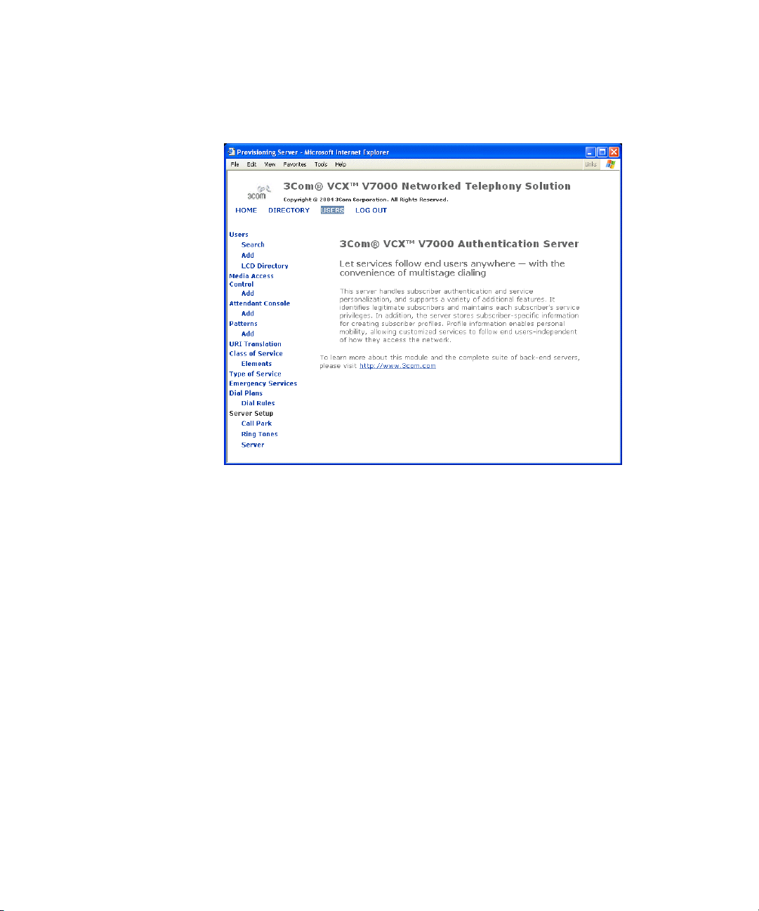
20 CHAPTER 1: CONFIGURING THE AUTHENTICATION SERVER
Figure 1 Authentication Server Main Page
Page 21
Configuring End Users 21
Configuring End Users
Use this feature to add and manage end users and end user phones.
Make searches to manage the URI addresses, call plans, and call plan
details associated with a specific end user. End user profiles can be added,
deleted, or modified.
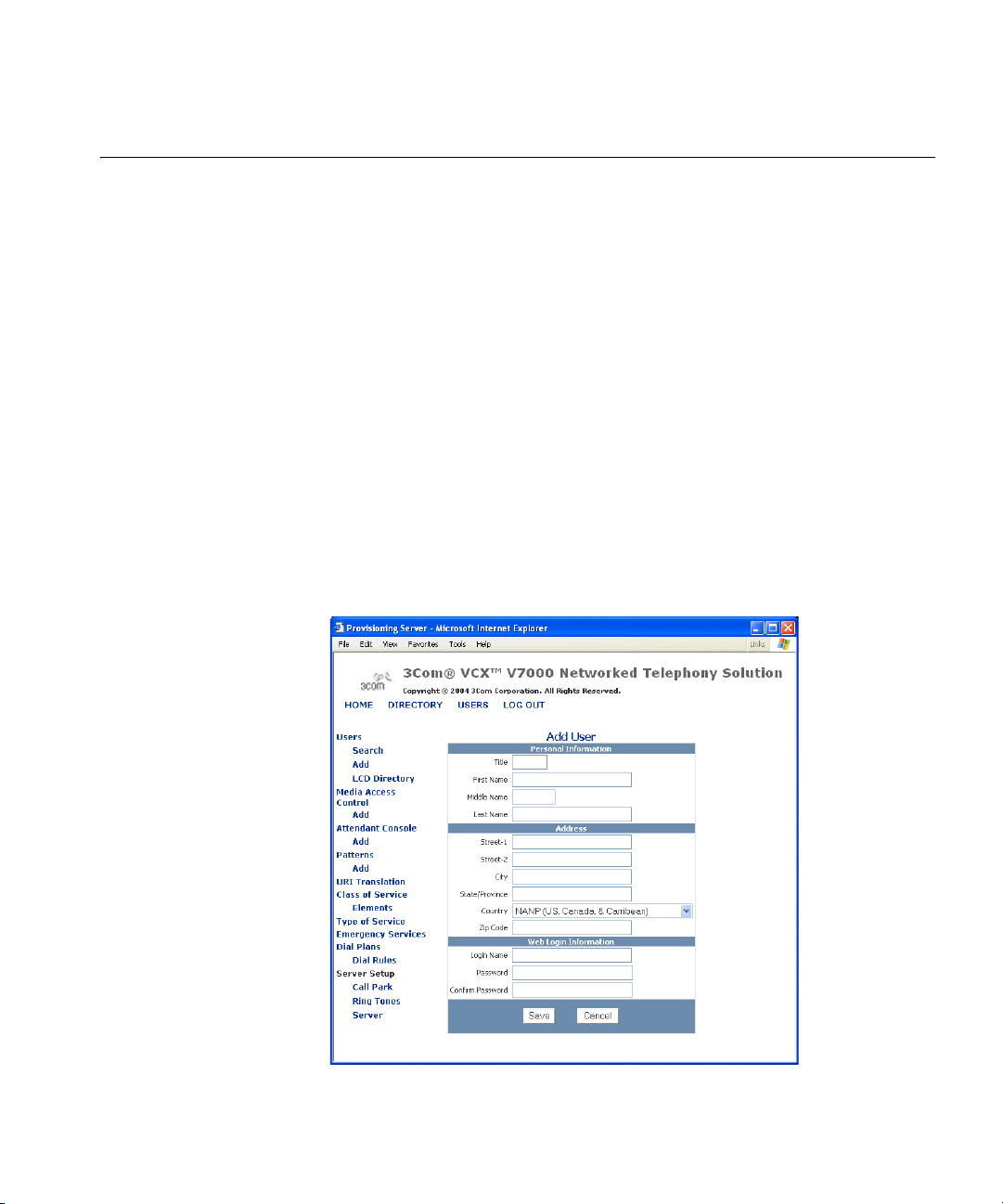
Adding End Users To add a new end user profile:
1 Under the Users heading, click Add. See Figure 1.
The Add User page appears.
The Add User page contains three editable sections:
■ Personal Information—full name and date of birth
■ Address—address of your location
■ Web Login Information—web login username and password
2 Fill in the three sections on the Add User page. See Figure 2.
Figure 2 Add User Window
3 In the Personal Information section, edit the following fields and use the
examples in Table 3 as a guide:
Page 22

22 CHAPTER 1: CONFIGURING THE AUTHENTICATION SERVER
Tab le 3 Adding Personal Information
Field Description Example Required?
Title The social title of the new
user
First Name The first name of the new
Middle Name The middle initial of the new
Last Name The last name of the new
user
user.
user.
4 In the Address section, edit the following fields and use the examples in
Table 4 as a guide:
Tab le 4 Adding Address Information
Field Description Example Required?
Street-1 The first line for the home
Street-2 The second line for the home
City The city for the home address of
State/
Province
Country The country for the home
ZIP Code The ZIP Code or Postal Code for
address of the new user.
address of the new user. Use this
field for apartment/unit numbers
or P.O. Box numbers.
the new user.
The state/province for the home
address of the new user.
address of the new user.
the home address of the new
user.
Miss, Mr., Mrs., Ms. No
Jane, John Yes
A., B., C., D. No
Doe, Roe Yes
1234 University St. Yes
P.O. Box 5678 No
Chicago Yes
IL Yes
NANP (US, Canada, &
Caribbean)
12345-6789 Yes
Yes
5 In the Web Login Information section, edit the following fields and use
the examples in Table 5 as a guide:
The end user will use their web login username and password to access
their phone online from the Calling Features User Interface.
Page 23

Tab le 5 Adding Web Login Password
Field Description Example Required?
Login Name The unique web login name for the
new user.
Password The unique password for the new
user.
Confirm Password The unique password for the new
user. Simply type the login
password again for verification
purposes.
Note: If the password and
confirmation do not match, an error
appears.
6 When you are finished, click Save.
Viewing All End Users To view all end user profiles:
1 From the left-hand side of the main page, click the Users heading.
The Users page appears.
Configuring End Users 23
JOHN YES
123ABC Yes
123ABC Yes
Each row on the Users page contains six columns of information for each
end user. Table 6 lists each column and describes the type of information
available in that column.
Tab le 6 Users Page—Columns of Information
Column Description Sample Content
Selection Use this column to select multiple users.
This is useful when deleting multiple
users.
Login Name This column contains a link which
allows you to edit the personal
information for an existing end user.
Name This column contains the first, middle,
and last names of an existing end user
(as entered in the Add User page). This
field is not editable.
Phones This column contains a link which
allows you to view and add phones to
an existing end user.
(continued)
N/A
JOHNTEST
John T. Smith
N/A
Page 24

24 CHAPTER 1: CONFIGURING THE AUTHENTICATION SERVER
Tab le 6 Users Page—Columns of Information (continued)
Column Description Sample Content
Actions This column contains three actions you
can perform for each end user:
■ Add Phone—use this to add a
■ Clone—use this option to clone an
■ Delete—use this option to delete
2 Use the Users page to manage phones and other end user-specific
features.
N/A
phone to an existing end user
existing end user
an existing end user
Searching for End
Users
To search for specific end users:
1 Under the Users heading, click Search.
The Search Users page appears.
2 Use the following case-sensitive fields to search for specific users:
■ First Name
■ Last Name
■ Login Name
■ Phone Address
To search for all users, leave the search fields empty.
3 Click Search.
To clear all of these fields, click Reset.
The Users pages appears.
4 View and edit end user profiles according to your customized needs.
Page 25

Configuring End Users 25
Editing End User
To edit an end user profile:
Profiles
1 Click the Users heading.
The Users page appears.
2 In the Login Name column, click the login name of the end user you want
to edit.
The Edit User page appears.
3 Make the necessary changes for this end user.
4 Click Save.
The Users page reappears with the changes saved for this end user.
Cloning End Users Clone an end user to save time. The cloning feature only clones basic end
user information, not specific phone features. This feature is particularly
useful when you are adding several users from the same geographical
region.
To clone an end user:
1 Search for the particular end user you want to clone.
See Searching for End Users on page 24.
2 From the Users page, click Clone in the Actions column.
The Edit User page appears.
3 Edit the fields with new information for the cloned end user.
4 Click Save.
The Users page appears with the cloned end user listed.
Page 26
26 CHAPTER 1: CONFIGURING THE AUTHENTICATION SERVER
Deleting End Users Use the administration provisioning server to delete one or more end user
profiles.
Deleting One End User
To delete one end users:
1 Search for the particular end user you want to delete.
See Searching for End Users on page 24.
If a phone exits for the user, delete the phone before deleting the user.
2 From the Users page, click Delete in the Actions column.
The Users page refreshes, showing the new list of end users.
Deleting Multiple End Users
To delete multiple end users:
1 Search for the particular end users you want to delete.
See Searching for End Users on page 24.
If a phone exits for the user, delete the phone before deleting the user.
2 From the Users page, select the checkbox preceding each end user you
want to delete.
3 At the top of the Users page, click Delete Selected.
The Users page refreshes, showing the new list of end users.
Page 27
Configuring User Phones 27
Configuring User Phones
Adding Phones To add a new phone for an existing end user:
Use the provisioning server to add, delete, and modify phones profiles for
an existing user. Also, use the provisioning server to customize calling
features for an existing user.
1 Search for a particular end user.
See “Searching for End Users” on page 24.
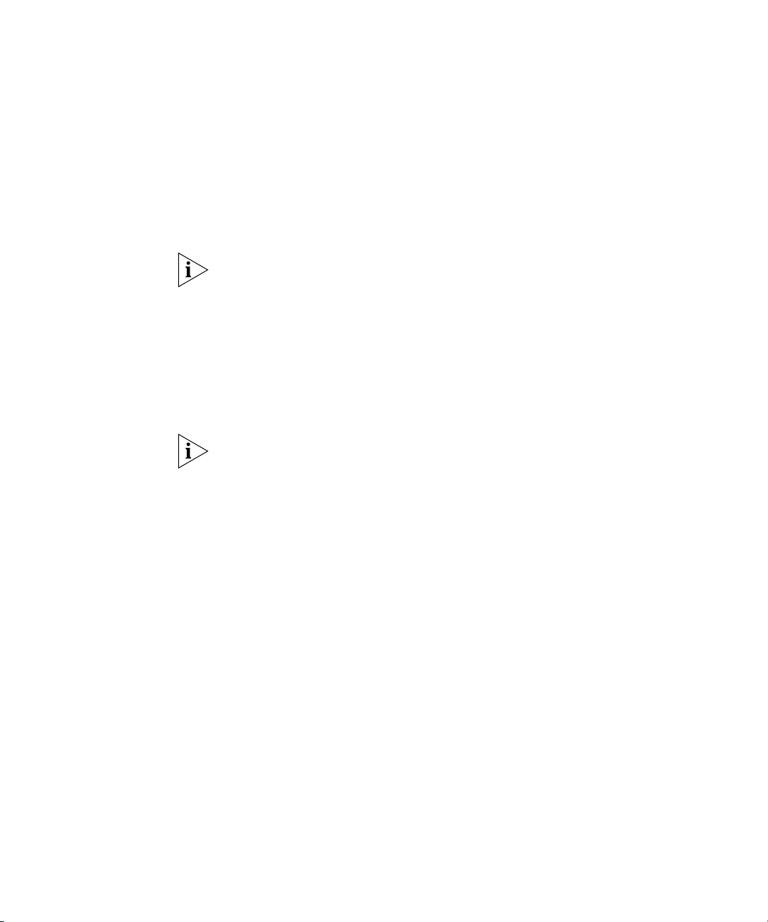
2 From the Users page, click Phones in the Phones column.
The User Phones page appears. See Figure 3.
Figure 3 User Phones Window
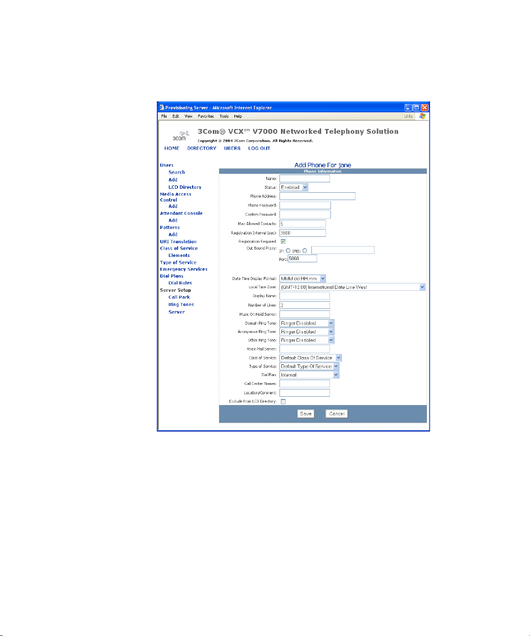
3 From the User Phones page, click Add Phone.
The Add Phone page appears. See Figure 4.
Page 28
28 CHAPTER 1: CONFIGURING THE AUTHENTICATION SERVER
Figure 4 Add Phone Window
4 Fill out the fields according to the descriptions in Table 7.
Page 29

Configuring User Phones 29
The Add Phone field descriptions are as follows:
Tab le 7 Add Phone Field Descriptions
Field Description
Name Indicates the unique name for the phone.
For example:
Home Office
Status Indicates the status of the phone. End users can only
Phone Address A unique phone address.
Phone Password Indicates the unique password for the phone and is used
Confirm Password Confirms the unique password for the phone.
Max Allowed Contacts Use this field to configure a maximum number of SIP
Registration Interval (sec) How often a registration message is sent to server to see
Registration Required Click if you want registration to be enabled.
Out Bound Proxy ■ IP — IP address of the out bound proxy.
(continued)
make calls on a particular phone if it is enabled.
Use the sip:<user_extension>@<host_name> format
for this field.
For example:
sip:2222@192.1.1.1
for phone registration.
Note: The first digit of the password cannot be the
number zero.
contacts, or phone registrations, for a particular phone.
End users can register at multiple phones so that they
can access all of their customized calling features. An
end user cannot exceed the maximum number of SIP
contacts.
Also, the SIP contacts are prioritized based on the
customized configuration of the phone. For more
information about SIP contacts, see “Adding Phone
Registrations” on page 40.
if it is active.
■ DNS — DNS of the out bound proxy.
■ Port— Port number of the out bound proxy.
Page 30

30 CHAPTER 1: CONFIGURING THE AUTHENTICATION SERVER
Tab le 7 Add Phone Field Descriptions (continued)
Field Description
Date Time Format Display Indicates the format of the phone’s LCD. An example of
Local Time Zone Time zone of where the server is located.
Display Name The name to be displayed on the phone’s LCD.
Number of Lines The number of lines on the phones, varies by type of
Music On Hold Server Address of the Music on Hold server.
Domain Ring Tone The type of ring tone you want to hear for phone calls
Anonymous Ring Tone The type of ring tone you want to hear from anonymous
Other Ring Tone The type of ring tone you want to hear for phone calls
Voice Mail Server Address of the voice mail server, where your phone
Class of Service Indicates what phone numbers an end user is allowed to
(continued)
what each format would like is provided.
■ MMM dd HH:mm — Nov 07 16:20
■ MMM dd hh:mm a — Nov 07 04:20 AM or
Nov 07 04:20 PM
■ MM dd HH mm — 11/07 16:20
■ MM dd HH mm — 11/07 04:20 AM or
11/ 07 04:20 PM
■ dd MMM HH mm — 07 Nov 16:20
■ dd MMM hh mm a — 07 Nov 04:20 AM or
07 Nov 04:20 PM
■ dd MM HH mm — 07/11 16:20
■ dd MM hh mm a — 07/11 04:20 AM or
07/11 04:20 PM
Note: Daylight savings is not automatically set so you
need to set a specific time zone from the drop-down
menu.
phone.
For example:
8475551212
within your network domain, which use Caller ID.
phone calls.
outside your network domain, which use Caller ID.
connects to so you can hear your voice mail messages.
For example, it is the UMS pilot number.
either place or receive. The phone numbers are bundles
into a Class of Service, which are configured in the
“Configuring Class of Service” section on page 60.
Page 31

Configuring User Phones 31
Tab le 7 Add Phone Field Descriptions (continued)
Field Description
Type of Service Indicates what feature bundle is assigned to the phone.
Type of Service bundles are configured in the
“Configuring Type of Service” section on page 65.
Dial Plan Dial plans are comprised of individual or bundled dial
Call Center Names Identifies all of the Call Centers the end user should be
Location/Comment This field is listed when a user lists all the phones in the
Exclude from LCD
Directory
rules and are configured in the Configuring Dial Plans.
Once dial plans are associated with a phone, the
configured phone numbers no longer require an end
user to press OK to place a call.
assigned to. If there are multiple Call Centers for an end
user; separate each Call Center with a comma.
LCD directory. You can provide specific information you
want listed such as the phone location.
To prevent phones from being listed in the LCD
Directory, check the checkbox.
5 Click Save.
The User Phones pages appears, showing the new phone.
Deleting Phones
from a User
When you delete a phone that is associated with an attendant console,
the attendant console configuration is also deleted. To prevent from
losing an attendant console configuration, first edit the associated phone
address for the attendant console so it does not use the same phone
address as the phone you want to delete using the instructions in
“Editing Attendant Console Basic Information” on page 54.
To delete a phone from a user:
1 Search for a particular end user.
See “Searching for End Users” on page 24.
2 From the Users page, click Phones in the Phones column for the end user
you want to delete a phone from.
The User Phones page appears.
3 Click the checkbox preceding the Name column in the same row as each
phone you want to delete.
4 Click Delete Selected.
The User Phones page reappears verifying the phone was deleted.
Page 32

32 CHAPTER 1: CONFIGURING THE AUTHENTICATION SERVER
Adding Phone
Features
To add phone (calling) features for an existing phone:
1 Search for a particular end user.
See “Searching for End Users” on page 24.
2 From the Users page, click Phones in the Phones column.
The User Phones page appears.
3 In the Actions column, click Features.
The Assigned Phone Features page appears.
4 From the Assigned Phone Features page, click Add Features.
The Add New Phone Features page appears.
Table 8 lists all of calling features available for a particular phone.
Tab le 8 Calling Features for Phones
Calling Feature Description
Call Forward Busy Use this feature to redirect incoming calls when this
phone is busy. If the end user has multiple lines on this
phone, the busy is defined as all lines exhausted with
existing calls. The access code must be within the
range of 10 through 99 and the first digit must be an
asterisk (*).
Call Forward Ring No
Answer
Call Forward Universal Use this feature to redirect all incoming calls. Use this
(continued)
Use this feature to redirect incoming calls when this
phone rings for a specific time period (in seconds). The
access code must be within the range of 10 through
99 and the first digit must be an asterisk (*).
feature when the end user is away from the phone for
an extended period of time. The access code must be
within the range of 10 through 99 and the first digit
must be an asterisk (*).
Page 33

Configuring User Phones 33
Tab le 8 Calling Features for Phones (continued)
Calling Feature Description
Caller Identity This feature configures the following features:
■ Calling Number Delivery—Use this feature if the
phone supports the caller ID display feature. If so,
the phone light emitting diode (LED) will display the
number for incoming calls.
■ Calling Name Delivery—Use this feature if the
phone supports the caller ID display feature. If so,
the phone light emitting diode (LED) will display the
name for incoming calls.
■ Call Identity Suppression Universal—Use this
feature to make a call from a phone without
delivering the callee’s name and phone number to
any other phone. The access code must be within
the range of 10 through 99 and the first digit must
be an asterisk (*).
■ Enable Call Identity Suppression Per Call—When
enabled, this feature allows an end user to make a
single call from their phone WITHOUT delivering
their name and phone number to another phone.
Use this feature on a per call basis by dialing the
appropriate access code before dialing the actual
phone number. This feature overrides Call Identity
Suppression Universal if it is enabled. The access
code must be within the range of 10 through 99
and the first digit must be an asterisk (*).
Note: In order for this feature to immediately take
affect, you need to log out of the telephone and
then log back in, otherwise; the feature will not
take affect until the phone’s configured registry
timer setting has elapsed.
■ Disable Call Identity Suppression Per Call—Enable
this feature to allow end users to make a single call
from their phone WITH delivering their name and
phone number to another phone. Use this feature
on a per call basis by dialing the appropriate access
code before dialing the actual phone number.This
feature overrides Call Identity Suppression Universal
if it is enabled. In the access code field, enter an
access code in the format of *67. The access code
must be within the range of 10 through 99 and the
first digit must be an asterisk (*).
(continued)
Page 34

34 CHAPTER 1: CONFIGURING THE AUTHENTICATION SERVER
Tab le 8 Calling Features for Phones (continued)
Calling Feature Description
Speed Dial When making a call, use a speed dial to provide
Voice Mail Address Use this feature to configure the desired voice mail
Directed Call Pickup By enabling this feature and creating a security code, a
short-cut dial strings for frequently used phone
numbers. The access codes are automatically assigned.
Users are assigned 12 speed dials with access codes
*11 through *22.
Speed dial phone addresses should not
sip:<telephone_extension>@<IP Address of host
server> format. Enter a speed dial phone number as
just a number such as 1000.
servers for this phone. You can configure up to three
voice mail servers.
Using this feature requires the phone to be subscribed
to a voice mail system.
Also, configure the voice mail indicator used for
supported phones:
Audio—Use this feature if end users want an audio
indicator to notify them when receiving new voice mail
messages.
Visual—Use this feature if end users want a visual
indicator to notify them when receiving new voice mail
messages.
Both—Use this feature if end users want both audio
and visual indicators to notify them when receiving
new voice mail messages.
Note: In addition to sending a standard Voice Mail
Notification, the SIP Proxy can inform a SIP Phone of
the type of indication to use (Audio, Visual, or Both)
with a 3Com proprietary SIP header. SIP phones can be
developed to integrate with the 3Com proprietary SIP
header so they can be provisioned using the Calling
Features User Interface. For phones that do not
recognize 3Com proprietary SIP headers, the indication
type needs to be configured on the phone itself.
user can answer their own telephone from another
desk. To answer the call a person uses an access code
from any telephone within the network domain, enters
their security code (end user defines), and then enters
the extension number of the ringing phone. This
transfers the call to the telephone they are on. The
access code must be within the range of 10 through
99 and the first digit must be an asterisk (*).
use the
Page 35

Configuring User Phones 35
5 Select the checkbox in front of the features you want to add and click
Add Selected.
A confirmation dialog box appears.
6 If you are satisfied with your selection, click OK.
If adding the Enable Call Identity Suppression feature, in order for this
feature to immediately take affect, you need to log out of the phone and
then log back in, otherwise; the feature will not take affect until the
phone’s configured registry timer setting has elapsed.
The Assigned Phone Features page reappears showing the new list of
phone features.
Editing Phone
Features
To edit calling features for existing phones:
1 Search for a particular end user.
See Searching for End Users on page 24.
2 From the Users page, click Phones in the Phones column.
The User Phones page appears.
3 In the Actions column, click Features.
The Assigned Phone Features page appears.
4 In the Actions column, click Edit Feature next to the feature you want to
edit.
The Edit Feature page appears for that particular phone feature. This
page changes depending on the feature you choose to edit.
5 Configure each phone feature according to the descriptions in Table 9.
The Edit Feature field descriptions are as follows, depending on the
feature:
Page 36

36 CHAPTER 1: CONFIGURING THE AUTHENTICATION SERVER
Tab le 9 Edit Phone Features Field Descriptions
Feature Format
Access Code
Caller Identity ■ Calling Number Delivery—N/A N/A
Default
■ Calling Name Delivery—N/A N/A
■ Call Identity Suppression Universal—N/A *83
■ Enable Call Identity Suppression Per
*82
Call—N/A
■ Disable Call Identity Suppression Per
*67
Call—N/A
Call Forward Busy Use the sip:<user_name>@<host_name>
*74
format for the Phone Address field.
Call Forward Ring
No Answer
Use the sip:<user_name>@<host_name>
format for the Phone Address field.
*76
The Time Out, seconds field is the time (in
seconds) for which the phone will ring before
being forwarded to the forwarding phone
address. A typical setting for this field is 15.
Call Forward
Universal
Use the sip:<user_name>@<host_name>
format for the Phone Address field.
*72
Directed Call Pickup N/A *52
Speed Dial The standard format for all access codes is *##,
for example *11. The access codes are
*11 through
*22
automatically assigned. Users are assigned 12
speed dials with access codes *11 through
*22.
When the Busy Lamp Flash (BLF) box is enabled
(checked), the lamp next to that speed dial on
the phone will be lit when the phone mapped
to the configured speed dial is in use.
Add a unique name for each speed dial
number.
SIP URI address for the phone using this speed
dial.
Voice Mail Address Use either an IP address <x.x.x.x> or
N/A
<mail.sip.host_name> format for the Address
1, Address 2, and Address 3 fields.
To reset any of these fields to their original setting, click Reset.
Access codes precede actual phone numbers in a typical dial string. To
use calling features requiring access codes, simply dial the appropriate
Page 37

Configuring User Phones 37
access code before dialing the actual phone number. The standard format
for all access codes is *##, for example *77.
6 Click Update to save your settings.
7 Click Cancel to return to The Assigned Phone Features page.
Deleting Phone
Features
Adding Phone
Restrictions
To delete one calling features for an existing phone:
1 Search for a particular end user.
See Searching for End Users on page 24.
2 From the Users page, click Phones in the Phones column.
The User Phones page appears.
3 In the Actions column, click Features.
The Assigned Phone Features page appears.
4 In the Actions column, click Delete Feature next to the feature you
want to delete.
Use call restrictions to block specific incoming and outgoing call patterns
for a specific phone. These are commonly referred to as black (block) and
white (allow) lists. You can configure black and white lists for both
incoming and outgoing calls.
If the incoming or outgoing number matches both the black list and
the white list (for example, if 847* is configured for black list and
847262* is configured for white list), the black list always takes
precedence.
The standard format for all dial patterns is <number pattern>*, for
example 900*.
To add restrictions to an existing phone:
1 Search for a particular end user.
See Searching for End Users on page 24.
2 From the Users page, click Phones in the Phones column.
The User Phones page appears.
3 From the User Phones page, click Call Restrictions in the Actions column.
Page 38

38 CHAPTER 1: CONFIGURING THE AUTHENTICATION SERVER
The Restrictions page appears.
4 From the Restrictions page, click Add Phone Restriction.
The Phone Restrictions page appears. See Figure 5.
Figure 5 Phone Restrictions Window
5 Fill out the fields according to the descriptions in Table 10.
The Phone Restrictions field descriptions are as follows:
Table 10 Phone Restrictions Field Descriptions
Field Description
Direction Configure the phone restriction direction using one of the
Type Configure the phone restriction type using one of the following:
(continued)
following:
■ OUT_GOING
■ IN_COMING
■ Blocked
■ Allowed
Page 39

Configuring User Phones 39
Table 10 Phone Restrictions Field Descriptions (continued)
Field Description
Owner Configure the phone restriction owner using one of the following:
■ EndUser
■ Administrator
Note: Phone restrictions owned by the Administrator will not be
seen by the end user (from the Calling Features User Interface).
Pattern Use the drop-down menu to select a previously used pattern or
type in a new pattern. For more information, see Configuring
Patterns.
6 Click Save.
The Restrictions page appears showing the new phone restriction.
7 Click Cancel to return to The User Phones page.
Adding Anonymous
Call Restrictions
Use anonymous call restrictions to block incoming calls without defined
patterns for a specific phone. With this feature incoming calls with
Identification Protection are blocked. This feature reduces anonymous
calls since the person that calls must allow their number to be identified
in order to communicate with you.
To add an anonymous phone restrictions to an existing phone:
1 Search for a particular end user.
See Searching for End Users on page 24.
2 From the Users page, click Phones in the Phones column.
The User Phones page appears.
3 From the User Phones page, click Call Restrictions in the Actions column.
The Restrictions page appears.
4 From the Restrictions page, click Add Anonymous Call Restriction.
5 An anonymous call restriction is automatically configured and added to
the Restrictions page.
Page 40

40 CHAPTER 1: CONFIGURING THE AUTHENTICATION SERVER
Deleting Phone
Restrictions
Adding Phone
Registrations
To delete restrictions for an existing phone:
1 Search for a particular end user.
See Searching for End Users on page 24.
2 From the Users page, click Phones in the Phones column.
The User Phones page appears.
3 From the User Phones page, click Call Restrictions in the Actions column.
The Restrictions page appears.
4 In the Actions column, click Delete next to the restriction you want to
delete.
Use this feature to add phone registrations, or SIP contacts, for a
particular phone. This features allows end users to register at multiple
phones so that they can access all of their customized calling features.
Also, end users can have multiple SIP contacts which are prioritized based
on their customized needs. End users cannot exceed the maximum
number of SIP contacts. For more information about the maximum
number of SIP contacts allowed, see Table 7.
End users can monitor their SIP contacts using the Calling Features
User Interface.
To add phone registrations to an existing phone:
1 Search for a particular end user.
See Searching for End Users on page 24.
2 From the Users page, click Phones in the Phones column.
The User Phones page appears.
3 From the User Phones page, click Registrations in the Actions column.
The Phone Registrations page appears.
4 From the Phone Registrations page, click Add Registration.
The Add Registration page appears. See Figure 6.
Page 41

Figure 6 Phone Registration Window
Configuring User Phones 41
5 Fill out the fields according to the descriptions in Table 11.
The Add Registration field descriptions are as follows:
Table 11 Add Registration Field Descriptions
Field Description
URI Address This is the URI address of the home phone. This field is not
Priority If end users have multiple SIP contacts, use this field to prioritize
End Time in
Seconds
Deletable Provisioning means that the SIP contact is static. This field is not
User Name User name for a particular SIP contact.
Host Host IP address or DNS server for a particular SIP contact.
Port The phone port for a particular SIP contact. A typical phone ports
(continued)
editable. For example, sip:<telephone_extension>@<IP Address
of host server>.
them.
Use this field to set the time limit for an inactive SIP contact.
editable.
is 5060.
Page 42

42 CHAPTER 1: CONFIGURING THE AUTHENTICATION SERVER
Table 11 Add Registration Field Descriptions (continued)
Field Description
Type Choose the type of SIP contact:
■ UnKnown
■ SIP
■ SIPS
Note: SIPS is used for future implementations only.
Contact URI This is an optional field to be used in the SIP Registration
message.
6 Click Save.
The Phone Registrations page appears showing the new phone
registration.
7 Click Cancel to return to The User Phones page.
Viewing Phone
Registrations
To view the phone registrations for an existing SIP device:
1 Search for a particular end user.
See Searching for End Users on page 24.
2 From the Users page, click Phones in the Phones column.
The User Phones page appears.
3 From the User Phones page, click Registrations in the Actions column.
The Phone Registrations page appears.
The Phone Registrations page contains 11 columns of information
available for each phone registration.
Table 12 lists each column and describes the type of information available
in that column.
Table 12 Phone Registrations Page
Column Description
Use this checkbox to delete more than one phone registration at
a time. If a box is checked, and then the Delete Selected
button is clicked, all of the selected phone registrations are
deleted.
(continued)
Page 43

Configuring User Phones 43
Table 12 Phone Registrations Page (continued)
Column Description
URI Address This field contains the URI address for a particular phone
registration.
Priority This field contains the registration priority for a particular phone
registration.
End Time This field contains the expiration time for a particular phone
Deletable This field indicates whether the phone registration is a
User Name This field contains the user name for a particular phone
Host This field contains the host IP address for a particular phone
Port This field contains the port number for a particular phone
Type This field indicates what type of phone registration this is.
Contact URI This field indicates what is to be used in the SIP Registration
Action Delete an individual phone registration from this column.
registration.
Provisioning (static) or Dynamic contact.
registration.
registration.
registration.
message.
Note: Deleting a phone registration de-registers the device from
the SIP proxy server.
When a SIP device de-registers from the SIP proxy, the device is not
automatically deleted from the Sip_Registration run-time table until an
internal job deletes the expired contact. This job runs once an hour.
4 Click Cancel to return to the User Phones page.
Viewing Call History To view the call history for an existing SIP device:
1 Search for a particular end user.
See Searching for End Users on page 24.
2 From the Users page, click Phones in the Phones column.
The User Phones page appears, see Figure 7.
3 From the User Phones page, click Call History in the Actions column.
The Call History page appears.
Page 44

44 CHAPTER 1: CONFIGURING THE AUTHENTICATION SERVER
Figure 7 Populated Call History
The Call History log contains 6 columns of information available for each
phone.
Table 13 lists each column and describes the type of information available
in that column.
Table 13 Call History Information for Phones
Column Description
Caller Address This field contains the address of the phone who initiated a
specific call (the calling party).
Calling Address This field contains the address of the phone who received a
Start Time
(YYYY-MM-DD
hh:mm:ss)
End Time
(YYYY-MM-DD
hh:mm:ss)
(continued)
specific call (the called party).
This field contains the date and time a call began.
Note: Any call where the start time equals zero (for
example, when a call is forwarded or not answered), the
date is translated to 1970-01-01.
This field contains the date and time a call ended.
Note: Any call where the end time equals zero (for
example, when a call is forwarded or not answered), the
date is translated to 1970-01-01.
Page 45

Configuring User Phones 45
Table 13 Call History Information for Phones (continued)
Column Description
Duration (hh:mm:ss) This field contains the time duration for a specific call.
Features Used This field contains a list of calling features used during a
specific call.
NOTE: If a speed dial is made using a mapped button,
nothing for the call is listed in the Features Used column. If
the same speed dial is made manually, the Features Used
column lists Speed Dial.
To get real-time call history, click Refresh at the bottom of the page.
4 To return to the User Phones page, click Back on your web browser.
Viewing Phone Ring
Tones
To view the ring tones assigned to an existing phone:
1 Search for a particular end user.
See Searching for End Users on page 24.
2 From the Users page, click Phones in the Phones column.
The User Phones page appears.
3 From the User Phones page, click Selective Ringing in the Actions column.
The Selective Call Ring Tones page appears. See Figure 8.
Page 46

46 CHAPTER 1: CONFIGURING THE AUTHENTICATION SERVER
Figure 8 Selective Call Ring Tones Window
The Selective Call Ring Tones page contains two columns of information
available for each phone registration.
Table 14 lists each column and describes the type of information available
in that column.
Table 14 Ring Tones Page Descriptions
Column Description
Phone Number This field contains the phone number of an incoming call that
Ring Tone This drop-down provides a selection of ring tones to assign to
you want to assign a specific ring tone to.
The phone number must be entered in this format:
sip:<phone extension>@<IP address of server>.
specific incoming phone numbers.
Note: The ring tones are configured in from the Configuring
Ring Tones section.
Page 47

Viewing the LCD Directory 47
Adding or Editing
Ring Tones of Specific
Phones
Viewing the LCD Directory
To add or edit ring tones of specific phones:
1 Search for a particular end user.
See Searching for End Users on page 24.
2 From the Users page, click Phones in the Phones column.
The User Phones page appears.
3 From the User Phones page, click Selective Ringing in the Actions column.
The Selective Call Ring Tones page appears. See Figure 8.
4 Fill out the fields according to the descriptions provided in Table 14.
5 Click Save.
The Selective Call Ring Tones page is updated.
6 Click Cancel to return to previous page you were at.
The LCD Directory provides a listing of every end user and their associated
extension(s) configured on the host server. This information is only
configured and editable by modifying the phone’s information, which can
be done by following the specific sections in the “Configuring User
Phones” section on page 27.
Only phones the administrator has allowed to be seen in the LCD
Directory appear. To change whether or not a phone can be seen, see
“Adding Phones” on page 27.
To view all the phones listed for a host server:
1 From the left-hand side of the GUI, under the Users heading, click LCD
Directory.
The LCD Directory page appears. See Figure 9.
Page 48

48 CHAPTER 1: CONFIGURING THE AUTHENTICATION SERVER
Figure 9 LCD Directory Window
Page 49

Configuring Media Access Control 49
Configuring Media Access Control
Adding a MAC
Address
The Media Access Control (MAC) address is used to physically identify
each telephone within the network. Every telephone has a unique MAC
address, which is located on the bottom of the telephone. In order to
associate a MAC address with the correct phone number, you need to
register them.
To add a MAC address:
1 From the left-hand side of the main page, click the Media Access Control
heading.
The Media Access Control List page appears.
2 From the Media Access Control List page, click Add MAC.
The Media Access Control page appears.
3 Fill in the fields according to Table 15.
Table 15 MAC Address field descriptions
Field Heading Description
Device Unique Address This is the MAC address field. The MAC address must be in
the format of 6 sets of two digit hex numbers, separated by
a colon.
For example: 00:e0:bb:13:48:5f.
NOTE: 3Com products have a MAC address that start with
00:e0:bb.
Phone URI The SIP phone’s unique extension or URI_ID value. It is
either null or an existing value of the table
ACCOUNT_URI_MAP.
Use the sip:<telephone_extension>@<IP Address of host
server> format for the field.
For example:
sip:2222@10.168.1.1
In the provisioning server, it is added by the URI_VALUE,
and the provisioning server associates the URI_ID with
URI_VALUE.
NOTE: Click Edit Phone to add or edit other end user
telephone properties assigned. See “Adding Phones” on
page 27 for more information.
(continued)
Page 50

50 CHAPTER 1: CONFIGURING THE AUTHENTICATION SERVER
Table 15 MAC Address field descriptions
Field Heading Description
Locked Indicated whether or not the telephone is disabled from the
Location Physical location of the phone. For example, you could
4 Click Save.
end user.
Checked - The end user cannot change their extension
using their telephone.
Unchecked - The end user can change their extension using
their telephone.
indicate what the building, room, or cube the telephone is
in.
Editing a MAC
Address
Deleting a MAC
Address
To edit a MAC address:
1 From the left-hand side of the main page, click the Media Access Control
heading.
The Media Access Control List page appears.
2 from the MAC Address column, click the MAC address you want to edit.
The Media Access Control page appears.
3 Edit the fields according to the descriptions in Table 15.
4 Click Save.
To delete a MAC address:
1 From the left-hand side of the main page, click the Media Access Control
heading.
The Media Access Control List page appears.
2 From the Media Access Control List page, click each checkbox preceding
the MAC Address column for each MAC address you want to delete.
3 Click Delete Selected.
Page 51

Configuring an Attendant Console 51
Configuring an Attendant Console
Supported Attendant
Console Feature
Buttons
Adding an Attendant
Console
The Attendant Console allows an attendant to manage call handling
within the enterprise more productively and quickly for end users. Calls
can be accepted and dispatched within the enterprise and allows an
attendant to verify if a telephone is busy. Up to three attendant consoles
can be configured for each VCX system.
The attendant console buttons support these features:
■ Call Hold
■ Call Park
■ Call Transfer
■ Conference
To add an Attendant Console:
1 From the left-hand side of the main page, click Add under the Attendant
Console heading.
The Attendant Console page appears. See Figure 10.
Figure 10 Attendant Console Window
Page 52

52 CHAPTER 1: CONFIGURING THE AUTHENTICATION SERVER
2 Fill in the fields according to the Table 18.
Table 18 lists the Attendant Console field descriptions.
Table 16 Attendant Console Field Description
Field Description
MAC Address MAC address of the attendant console.
Location Textual description of where Attendant Console is located such
as a cube, office, or geographic area.
Associated User
Phone Address
Associated User
MAC Address
Subscription
Interval (sec)
The address (sip:1234@10.67.10.46) of the phone to which the
Attendant Console is associated with.
MAC address of the phone to which the Attendant Console is
associated with.
Interval in seconds the Attendant Console updates itself with
changes to its Button to Feature Mapping.
3 Click Save.
The Attendant Console page appears, showing the added attendant
console.
4 Map the telephone features to the desired feature buttons on the
attendant console.
a From the Attendant Console page, under the Actions column, click
Feature Mappings in the same row as the attendant console you want
to edit.
The Attendant Console page appears, which allows the attendant
console buttons to be mapped to specific features.
b There are four feature buttons that can be mapped to the four
available telephone features. The features available are:
■ Call Hold
■ Call Park
■ Call Transfer
■ Conference
c From each feature drop-down list, assign a unique feature to each
feature button (1 through 4).
d Click Save.
The Attendant Console page refreshes, and the feature mappings are
assigned.
Page 53

Configuring an Attendant Console 53
5 Map the phone extensions to the attendant console buttons. The
attendant console allows up to 100 telephones to be configured.
a From the Attendant Console page, under the Actions column, click
Extension Mappings in the same row as the attendant console you
want to edit.
The Attendant Console page appears, which allows the attendant
console buttons to be mapped to specific extensions.
b There are 100 fields available to configure telephone extensions. To
configure extensions 1-50, click the 1-50 button; and to configure
extensions 51-100, click the 51-100 button. Extensions should be
configured using this format:
sip:<extension>@<domain name or IP address>
For example, sip:1234@3com.com or sip:1234@10.10.0.0
c Click Save.
The Attendant Console page refreshes, and the extension mappings
are configured.
6 Reboot the telephones that where mapped to the attendant console.
Editing Feature
Mapping Buttons on
an Attendant Console
To edit a telephone feature button on an attendant console:
1 From the left-hand side of the main page, click Attendant Console.
The Attendant Console page appears.
2 From the Actions column, in the same row as the attendant console you
want to edit feature button mappings for, click Feature Mappings.
The Attendant Console page appears that allows feature mapping
configuration.
3 For each feature drop-down list, reassign a unique feature to each feature
button (1 through 4).
4 Click Save.
The Attendant Console page refreshes and the feature mappings are
reassigned.
Page 54

54 CHAPTER 1: CONFIGURING THE AUTHENTICATION SERVER
Editing Extensions on
an Attendant Console
Editing Attendant
Console Basic
Information
To edit the extensions for a attendant console:
1 From the left-hand side of the main page, click Attendant Console.
The Attendant Console page appears.
2 From the Actions column, in the same row as the attendant console you
want to edit telephone extension mappings for, click Extension
Mappings.
The Attendant Console page appears that allows telephone extension
mapping configuration.
3 Change any telephone extensions that need to be edited.
4 Click Save.
The Attendant Console page refreshes, and the telephone extension
mappings are reconfigured.
5 Reboot the telephones that where mapped to the attendant console.
To edit attendant console MAC addresses, location, associated user
phone address, and subscription interval:
1 From the left-hand side of the main page, click Attendant Console.
The Attendant Console page appears.
2 From the MAC Address heading, click the attendant console you want to
edit.
The Attendant Console page appears, which allows the basic information
to be edited.
3 Change the field values according to the descriptions in Table 16 on
page 52.
4 Click Save.
The Attendant Console page refreshes, and the attendant console basics
are reconfigured.
5 Reboot the telephones that where mapped to the attendant console.
Page 55

Configuring Patterns 55
Deleting an
Attendant Console
Attendant Console
Busy Lamp Flash
Descriptions
To delete an attendant console:
1 From the left-hand side of the main page, click Attendant Console.
The Attendant Console page appears.
2 Click the checkbox(es) preceding the MAC Address(es) for each attendant
console(s) you want to delete.
3 Click Delete Selected.
A pop-up window appears verifying you really want to delete the
attendant console.
4 Click OK.
5 The Attendant Console page refreshes, verifying the attendant console
was deleted.
The attendant can use the Busy Lamp Flash (BLF) indicators that are next
to each extension on the attendant console to determine the state of an
end user’s telephone. Any telephone that is mapped to a button on the
attendant console use the BLF indicators.
The BLF indicators are coded as follows:
Table 17 Attendant Console BLF Descriptions
Configuring Patterns
BLF Indicator State Description
Off The end user’s phone is not busy (on-hook) and available.
On (solid light) The end user’s phone is busy (off-hook) and in use.
This section provides information on how to view, add, and delete
patterns.
To add a pattern:
1 From the left-hand side of the main page, click the Patterns heading.
The List Patterns page appears.
2 From the List Patterns page, click Add Pattern.
The Add Pattern page appears. See Figure 11.
Page 56

56 CHAPTER 1: CONFIGURING THE AUTHENTICATION SERVER
Figure 11 Add Pattern Window
3 Fill in the fields according to the Table 18.
Table 18 lists the Add Pattern field descriptions.
Table 18 Add Pattern Field Description
Field Description
PATTERN NAME A unique name for the pattern.
PATTERN This is the pattern value. It can contain a wild card (*), but only
one or zero. If a * is present, it should be the last character in
the pattern value.
4 Click Save.
The List Patterns page appears, showing the added pattern.
Page 57

Configuring URI Translation Patterns 57
Configuring URI Translation Patterns
Adding URI
Translation Pattern
To successfully communicate with other voice networks, the
authentication server translates numbers based on source and destination
calling patterns.
For example, if an end user dials number 456789 and the URI translation
is configured so that the source pattern equals *and the destination
pattern equals 456*, the result pattern is *@3com.com. In this example,
the “*” is 789 because the user dialed 456789 and the destination
pattern is 456*. 789 is used in place of the * in the result pattern, and
the URI translation is 789@3com.com. 456789, the original phone
number, gets translated as 789@3com.com and is processed accordingly.
You can configure a URI translations to support VPN translations.
To add a URI translation:
1 From the left-hand side of the main page, click the URI Translation
heading.
The List URI Translation Patterns page appears.
2 From the List URI Translation Patterns page, click Add URI Translation.
The URI Translation page appears. See Figure 12.
Page 58

58 CHAPTER 1: CONFIGURING THE AUTHENTICATION SERVER
Figure 12 URI Translation Window
3 Use the drop-down menus according to Table 19. Patterns need to be
pre-configured before you create any URI Translations. See “Configuring
Patterns”
Table 19 URI Translation Menu Descriptions
Field Description
Group Name Assign the URI translation to a group:
Source Pattern The source pattern where the call is coming from.
Result Source Pattern This is the number that is displayed on the destination
Destination Pattern The called party for this URI translation.
Result Destination Pattern The result pattern for this URI translation.
Active Checked – this URI Translation is enabled.
on page 55 for more information.
■ Virtual Private Network
caller’s LCD.
Not Checked – this URI Translation is disabled.
This example shows a call being made from one company in the United
States to another company in the United States. The call is outside the
caller’s network and the caller does not want their extension made visible
to the callee. A Result Source Pattern is used to display a different
number, such as the 800 number of the caller’s company.
Page 59

Configuring URI Translation Patterns 59
If the caller’s telephone number is 847-555-2122, the 800 number for the
caller’s company is 800-555-3433, the telephone number of the caller
508-555-4344, and the caller needs to dial a “9” to reach an outside line,
you would set up an URI Translation in this manner:
Deleting URI
Translation Patterns
Source Pattern –
sip:8*
This signifies any telephone number that starts with an 8 (in this case
847-555-2122) within the company should follow the patterns set for the
destination pattern.
Result Source Pattern –
sip:8005553433*
This is the number that should be displayed on the caller’s LCD.
Destination Pattern –
sip:91*
This strips the 91 from the number once it reaches the gateway. Since this
call is being made within the United States to another area code and the
caller needs to dial 9 to get an outside line, the pattern is set up as
sip:91*. If a caller needed to reach a telephone outside the United States,
the Destination Pattern would be configured as sip:901*.
Result Destination Pattern –
sip:1*
This strips the 1 from the number as it leaves the gateway.
4 Click Save.
The List URI Translation Patterns page appears, showing the added URI
translation pattern.
To delete URI translation patterns:
1 From the left-hand side of the main page, click the URI Translation
heading.
The List URI Translation Patterns page appears.
2 From the List URI Translation Patterns page, check the checkbox(es)
preceding the pattern you want to delete.
3 Click Delete Selected.
The List URI Translation Patterns page refreshes, showing the deleted URI
translation pattern.
Page 60

60 CHAPTER 1: CONFIGURING THE AUTHENTICATION SERVER
Configuring Class of Service
Adding a Class of
Service
Class of Service indicates what phone numbers an end user is allowed to
either place or receive. Class of Services are comprised of one or more
elements. Elements are made of patterns, which are associated with a
phone number type such as Local or Emergency (varies by country). By
creating Class of Services, it makes it easier for you to configure end user
phones since the Class of Service names are added to a drop-down menu
when you configure an end user phone and you can apply the same
configuration across multiple telephones.
The emergency dialable digits are controlled by the ERL screens. If the
emergency digits are identified by an ERL then those emergency
dialable digits will not be applied a Class of Service treatment. Just
because a Class of Service Element is named Emergency and is
blacklisted does not mean that Emergency calls will not go through.
To add a Class of Service:
1 In the left-hand side of the main page, click the Class of Service heading.
The Class Of Service List page appears.
2 From the Type name of new class field, type in unique name to describe
the new Class of Service.
3 Click Add. The Class of Service List page refreshes showing the recently
added Class of Service.
4 From the Name column, click the name of the new Class of Service. The
Class Of Service Details For <Class of Service Name> page appears.
Page 61

Configuring Class of Service 61
Figure 13 Class of Service Details For <Class of Service Name> Window
5 Add elements to the Class of Service by selecting an element from the
Select element to add it to the class drop-down menu.
6 Click Add. The Class Of Service Details For <Class of Service Name> page
refreshes. Continue to add as many elements as you want to the Class of
Service.
7 For each element you can configure whether or not inbound calls are
allowed to be received and if outbound calls are allowed to be placed. In
each element row, click under the Inbound calls and Outbound calls
heading to either enable or disable these types of calls.
■ If Whitelist is listed — These types of elements (calls) are allowed to be
placed or received.
■ If Blacklist is listed — These types of elements (calls) are not allowed to
be placed or received.
8 For each Class of Service, Trunk to Trunk dialing can be configured. If
enabled, end users are allowed to transfer calls from within the phone
system to outside the phone system or to forward a call from outside the
phone system to somewhere else outside the phone system. If it says
Whitelist next to Trunk to Trunk, this feature is allowed.
Page 62

62 CHAPTER 1: CONFIGURING THE AUTHENTICATION SERVER
Enabling or Disabling
Inbound or Outbound
Calls in a Class of
Service
Adding or Deleting
Elements from a Class
of Service
To enable or disable inbound or outbound calls in a Class of Service:
1 From the left-hand side of the main page, click the Class of Service
heading. The Class Of Service List page appears.
2 From the Name column, click the name of the Class of Service you want
to edit. The Class Of Service Details For <Class of Service Name> page
appears.
■ If you want to enable or disable an inbound call:
From the Inbound calls column, either the word Whitelist or Blacklist is
listed and represents what authorization state the element is in. To
change the state, click the word Whitelist (or Blacklist depending on
configuration) to make it the opposite of what is listed.
■ If you want to enable or disable an outbound call:
From the Outbound calls column, either the word Blacklist or Whitelist
is listed and represents what authorization state the element is in. To
change the state, click the word Whitelist (or Blacklist depending on
configuration) to make it the opposite of what is listed.
To add or delete elements from a Class of Service:
1 From the left-hand side of the main page, click the Class of Service
heading. The Class Of Service List page appears.
2 From the Name column, click the name of the Class of Service you want
to edit. The Class Of Service Details For <Class of Service Name> page
appears.
To add elements to a Class of Service:
a From the Select element to add it to the class drop-down menu,
choose an element to add to the Class of Service.
b Click Add. The Class Of Service Details For <Class of Service Name>
page refreshes. Continue to add as many elements as you want to the
class of service.
c For each element, configure whether or not inbound calls are allowed
to be received and if outbound calls are allowed to be placed. In each
Page 63

Configuring Class of Service 63
element row, click under the Inbound calls and Outbound calls
heading to either enable or disable these types of calls.
■ If Whitelist is listed — These types of elements (calls) are allowed to be
placed or received.
■ If Blacklist is listed — These types of elements (calls) are not allowed to
be placed or received.
To delete elements from a Class of Service:
a From the Action column, click Remove from class in the same row as
the element that you want to delete.
The Class Of Service Details For <Class of Service Name> page
refreshes, showing the deleted element.
Enabling or Disabling
Trunk to Trunk Calls
for a Class of Service
To enable or disable Trunk to Trunk calls for a Class of Service:
1 From the left-hand side of the main page, click the Class of Service
heading. The Class Of Service List page appears.
2 From the Name column, click the name of the Class of Service you want
to edit. The Class Of Service Details For <Class of Service Name> page
appears.
3 Following the Tru nk To Tru nk heading, either the word Blacklist or
Whitelist is listed and represents what authorization state the Class of
Service is in. To change the state, click the word Whitelist (or Blacklist
depending on current configuration) to make it the opposite of what is
listed.
The Class Of Service Details For <Class of Service Name> page refreshes,
showing the update Trunk to Trunk call state.
Page 64

64 CHAPTER 1: CONFIGURING THE AUTHENTICATION SERVER
Configuring Class of Service Elements
Adding Class of
Service Elements
Elements are made of patterns, which are associated with a phone
number type such as Local or Emergency. Elements are needed so Class
of Service types can be created. Any element created is added to a
drop-down menu for when you go to add or edit a Class of Service.
To add a Class of Service element:
1 From the left-hand side of the main page, under the Class of Service
heading, click Elements. The Elements Of Class Of Service page appears.
2 From the Type name of new element field, type a name to define the
element.
3 Click Add. The Elements Of Class Of Service page refreshes showing the
new element.
4 Click the new element from the Name column to create patterns to
associate with the element.
5 The Patterns For <Element Name> page appears. See Figure 14.
Figure 14 Patterns For <Element Name> Window
Page 65

Configuring Type of Service 65
6 From the Type pattern value you want to add to element field, type a
pattern for the element.
7 Click Add. The Patterns For <Element Name> page refreshes, showing
the recently added pattern. Continue to add as many patterns as you
want to associate with that element.
Editing Class of
Service Elements
Configuring Type of Service
Editing a class of service element allows you to either delete or add a new
pattern to an element. You cannot revise a pattern once it has been
added to an element, you can only delete a pattern you no longer want
and add a new pattern.
To edit a Class of Service element:
1 From the left-hand side of the main page, under the Class of Service
heading, click Elements. The Elements Of Class Of Service page appears.
2 From the Name column, click on the element you want to edit. The
Patterns For <Element Name> page appears.
a To delete a pattern, from the Action column, click Delete in the same
row as the pattern you want to delete.
b To add a new pattern, type a new pattern in the Type pattern value
you want to add to element field and click Add.
3 The Patterns For <Element Name> page refreshes showing the edited
element.
Type of Service indicates what phone features an end user is allowed to
have. Type of Services are comprised of one or more phone features that
are bundled. For instance, if there are common phone feature
configurations, you can bundle those configurations into one Type of
Service so it makes end user phone configuration easier. The configured
Type of Service names are added to a drop-down menu when you
configure an end user phone.
Page 66

66 CHAPTER 1: CONFIGURING THE AUTHENTICATION SERVER
Adding a Type of
Service
To add a Type of Service:
1 From the left-hand side of the main page, click the Type of Service
heading. The Types Of Service List page appears. See Figure 15.
Figure 15 Types of Service List Window
2 From the Type name of new type field, type in a unique name to describe
the new Type of Service.
3 Click Add. The Types of Service List page refreshes showing the recently
added Type of Service.
4 From the Name column, click the name of the new Type of Service. The
Type Of Service Details For <Type of Service Name> page appears. See
Figure 16.
Page 67

Configuring Type of Service 67
Figure 16 Type Of Service Details For <Type of Service Name> Window
Deleting Type of
Services
5 Add a feature to the Type of Service by selecting a feature from the Select
feature to add it to the type drop-down menu.
Features descriptions are provided in the Adding Phone Features section
on page 32.
6 Click Add. The Type Of Service Details For <Class of Service Name> page
refreshes. Continue to add as many features as you want to the Type of
Service.
To delete a Type of Service:
1 From the left-hand side of the main page, click the Type of Service
heading. The Types Of Service List page appears.
2 From the Action column, click Delete in the same row as the Type of
Service you want to delete. The Types Of Ser vic e List page refreshes.
Page 68

68 CHAPTER 1: CONFIGURING THE AUTHENTICATION SERVER
Editing Type of
Services
To edit the features assigned to a Type of Service:
1 From the left-hand side of the main page, click the Type of Service
heading. The Types Of Service List page appears.
2 From the Name column, click the name of the Type of Service you want to
edit. The Type Of Service Details For <Type of Service Name> page
appears.
To add another feature to the Type of Service:
a Add a feature to the Type of Service by selecting a feature from the
Select feature to add it to the type drop-down menu.
Features descriptions are provided in the Adding Phone Features section
on page 32.
b Click Add. The Type Of Service Details For <Type of Service Name>
page refreshes. Continue to add as many features as you want to the
Type of Service.
To delete a feature from the Type of Service:
a From the Action column, click Remove from type in the same row as
the feature you want to delete. The Type Of Service Details For <Type
of Service Name> page refreshes showing the deleted feature.
Configuring Emergency Services
An Emergency Response Location (ERL) is defined as a location to which
an emergency team may be dispatched. The complete VCX system is
organized, from an emergency services point of view, into various ERLs.
For instance, telephones can be assigned unique ERLs based on a
geographic or physical location.
Each phone (uniquely identified by the assigned IP address) is part of a
unique ERL and each ERL is assigned a location-wide emergency callback
phone number. In addition, a set of emergency gateways are specified,
which are used to directly reach the emergency service provided in case
the Call Processor is down.
A set of ELINs are assigned to each ERL, so the phones in a particular ERL
have a pool of ELINs. An emergency caller is assigned an ELIN from this
shared pool. This association is used to callback the emergency caller. If all
the ELINs associated with an ERL are in use, the location specific
emergency callback number is used instead.
Page 69

Configuring Emergency Services 69
To ensure that emergency calls always go through, a set of system-wide
defaults are defined — the callback phone number and an emergency
gateway, identified by its IP address. These system defaults are used for
phones which are not part of any ELIN.
The emergency dialable digits are controlled by the ERL screens. If the
emergency digits are identified by an ERL then those emergency
dialable digits will not be applied a Class of Service treatment. Just
because a Class of Service Element is named Emergency and is
blacklisted does not mean that Emergency calls will not go through.
Adding ERLs When ERLs are configured, you can configure Emergency Location
Identification Numbers (ELIN), which are assigned through an
emergency services administrator.
To add an ERL:
1 From the left-hand side of the Users main page, click the Emergency
Services heading.
The Emergency Response Locations page appears. See Figure 17.
Figure 17 Emergency Defaults and Emergency Response Locations Window
Page 70

70 CHAPTER 1: CONFIGURING THE AUTHENTICATION SERVER
2 Click Add New ERL.
The Emergency Location page appears.
3 In the Location field, type a descriptive identifier for the location the ERL
is for based on geographic or physical location. For example, building
XYX, 1st floor. There is a 10 character limit.
4 In the Emergency Callback Phone field, type the phone number of the
contact person responsible for emergency situations within an
organization (for example, a security guard).
5 Click Save.
The ERL is added to the Emergency Response Location heading. See
Figure 18.
Figure 18 Emergency Defaults and Emergency Response Locations Window
6 Add an IP address range for the ERL.
This specifies which telephones should be included within this ERL (for
example, all telephones on the 1st floor of a building). Each phone in an
ERL is assigned an IP address from a range of IP addresses specified by
network address and netmask.
a From the Location Settings heading, click IP Ranges within the same
row as the ERL you want to configure.
Page 71

Configuring Emergency Services 71
The List of IP Ranges for <Name of ERL> page appears.
b Click Add New.
The IP Address Range page appears.
c In the IP Address field, type the IP network address for phones you
want to include in this ERL.
d In the Subnet Mask field, type the subnet mask for this IP address
range.
e Click Save.
The List of IP Ranges for <Name of ERL> page refreshes showing the
new IP address range.
7 Configure the Emergency Digits for the ERL.
Configuring the Emergency Digits (numbers) signals to the gateway that
the call being dialed is an emergency number. Any numbers configured
are marked as emergency calls and handled differently in case of a
disconnect.
a Click <Name of ERL> from the top of the List of IP Ranges for <Name
of ERL> page to return to the ERL configuration page.
b From the Location Settings heading, click Emergency Digits within the
same row as the ERL you want to configure.
The Emergency Digits For <Name of ERL> page appears.
c Click Add New.
d From the Emergency Number field, type an emergency number to
signal to the gateway that when this number is dialed, treat it as an
emergency number (for example, sip:911@<IP address of server>).
e Click Save.
f The Emergency Digits For <Name of ERL> page refreshes showing the
new emergency digit (number).
g If you have more Emergency Digits (numbers) to add, repeat step c
through step e.
8 Configure the Emergency Gateway IP for the ERL.
Configuring the Emergency Gateway IP specifies the address of the
gateway to be used to reach an emergency service provider in case the
VCX Call Processor is down. You can configure multiple gateways for a
redundant configuration.
Page 72

72 CHAPTER 1: CONFIGURING THE AUTHENTICATION SERVER
a Click <Name of ERL> from the top of the Emergency Digits For <Name
of ERL> page to return to the ERL configuration page.
b Click Emergency Gateway IP within the same row as the ERL you want
to configure.
The Emergency Gateway IP Addresses For <Name of ERL> page
appears.
c Click Add New.
The Gateway IP Address page appears.
d In the Gateway IP Address field, type the IP address of the gateway
you want calls to be routed to for the IP addresses (telephones) within
the ERL.
e Click Save.
The Emergency Gateway IP Addresses For <Name of ERL> page
refreshes, showing the emergency gateway.
f If you have more Emergency Gateways to add, repeat step b through
step e.
9 Configure the Emergency Lines for the ERL.
Configuring the Emergency Lines determines which ELINs should be
assigned to each ERL. You can configure multiple ELINs for each ERL.
a Click <Name of ERL> from the top of the Emergency Digits For <Name
of ERL> page to return to the ERL configuration page.
b Click Emergency Lines within the same row as the ERL you want to
configure.
The Emergency Line ID Numbers <Name of ERL> page appears.
c Click Add New ELIN.
The Emergency Line ID Numbers page appears.
d From the ELIN field, type the Emergency Location Identification
Number.
e In the Association Release Timer field, type in the amount of time you
want to leave the ELIN associated to the emergency caller. This
number is entered as a string in hours and the range is 1 through 24.
This association is used to callback the emergency caller. After the
configured time expires, the association between the emergency caller
and ELIN is dropped. In case an ELIN is not in use, it can be assigned to
Page 73

Configuring Emergency Services 73
a new emergency caller and the association with an older emergency
caller is overwritten with the association of the new emergency caller.
f In the Usage Release Timer field, type in the maximum amount of time
you want to allow the ELIN to remain in use. This number is entered as
a string in hours and the range is 1 through 24. Normally, an ELIN is
freed when the emergency service provider goes on-hook before the
emergency caller goes on-hook, otherwise, the ELIN is kept in use for
the duration of this timer.
g Click Save.
The Emergency Line ID Numbers <Name of ERL> page refreshes,
showing the ELIN.
h If you have more ELINs to add, repeat step b through step g.
The ERL is now configured.
Adding or Editing the
Emergency Defaults
The emergency defaults are used when there is no information in the
emergency response database for a emergency caller (phone IP address).
Typically, phone IP addresses are stored within ranges for a defined ERL.
If Emergency service settings are changed, (for example, the gateway IP
address or emergency digits) they will not take effect until the telephones
are power cycled. A simple logout/login of the telephone is not adequate
enough.
To add or edit the emergency defaults:
1 From the left-hand side of the Users main page, click the Emergency
Services heading.
The Emergency Defaults page appears.
2 In the IP Address field, type the IP address of a system-wide emergency
gateway.
3 In the Emergency Callback Phone field, type the phone number of the
contact person responsible for emergency situations within the
organization (for example, a security guard).
4 Click Save.
The Emergency Default is applied to the entire organization.
Page 74

74 CHAPTER 1: CONFIGURING THE AUTHENTICATION SERVER
Deleting ERLs To de le te an E RL :
1 From the left-hand side of the Users main page, click the Emergency
Services heading.
The Emergency Response Locations page appears.
2 Click the checkbox(es) preceding the ERL(s) you want to delete.
3 Click Delete Selected.
A pop-up window appears, verifying if you really want to delete the
ERL(s).
4 Click OK.
The Emergency Response Location page refreshes, verifying the ERL(s)
were deleted.
Editing IP Addresses
of an ERL
To edit an IP address range for the ERL.
If Emergency service settings are changed, (for example, the gateway IP
address or emergency digits) they will not take effect until the telephones
are power cycled. A simple logout/login of the telephone is not adequate
enough.
1 From the left-hand side of the Users main page, click the Emergency
Services heading.
The Emergency Response Locations page appears.
2 From the Location Settings heading, click within the same row as the ERL
you want to edit.
The List of IP Ranges for <Name of ERL> page appears.
3 From the Network IP heading, click the IP address range you want to edit.
The IP Address Range page appears.
4 In the IP Address field, type the IP network address for phones you want
to include in this ERL.
5 In the Subnet Mask field, type the subnet mask for this IP address range.
6 Click Save.
The List of IP Ranges for <Name of ERL> page refreshes showing the new
IP address range.
Page 75

Configuring Emergency Services 75
Deleting IP Addresses
from an ERL
Editing Emergency
Digits
To delete an IP address range from an ERL.
1 From the left-hand side of the Users main page, click the Emergency
Services heading.
The Emergency Response Locations page appears.
2 From the Location Settings heading, click IP Ranges within the same row
as the ERL you want to delete IP address from.
The List of IP Ranges for <Name of ERL> page appears.
3 Click the checkbox(es) preceding the IP address(es) you want to delete.
4 Click Delete Selected.
A pop-up window appears, verifying if you really want to delete the IP
address(es).
5 Click OK.
The List of IP Ranges for <Name of ERL> page refreshes verifying the IP
address(es) were deleted.
To edit an Emergency Digit for the ERL.
If Emergency service settings are changed, (for example, the gateway IP
address or emergency digits) they will not take effect until the telephones
are power cycled. A simple logout/login of the telephone is not adequate
enough.
1 From the left-hand side of the Users main page, click the Emergency
Services heading.
The Emergency Response Locations page appears.
2 From the Location Settings heading, click Emergency Digits within the
same row as the ERL you want to edit.
The Emergency Digits For <Name of ERL> page appears.
3 From the Emergency Number heading, click the telephone you want to
edit.
The Emergency Number page appears.
4 From the Emergency Number field, edit the emergency number.
5 Click Save.
The Emergency Digits For <Name of ERL> page refreshes showing the
new Emergency Digit.
Page 76

76 CHAPTER 1: CONFIGURING THE AUTHENTICATION SERVER
Deleting Emergency
Digits from an ERL
Editing Emergency
Gateway IP
Addresses from an
ERL
To delete an Emergency Digit from an ERL.
1 From the left-hand side of the Users main page, click the Emergency
Services heading.
The Emergency Response Locations page appears.
2 From the Location Settings heading, click Emergency Digits within the
same row as the ERL you want to delete an Emergency Digit from.
The Emergency Digits For <Name of ERL> page appears.
3 Click the checkbox(es) preceding the Emergency Digit(s) you want to
delete.
4 Click Delete Selected.
A pop-up window appears, verifying if you really want to delete the
Emergency Digit(s).
5 Click OK.
The Emergency Digits For <Name of ERL> page refreshes verifying that
the Emergency Digit(s) were deleted.
To edit an Emergency Gateway IP Address for the ERL.
If Emergency service settings are changed, (for example, the gateway IP
address or emergency digits) they will not take effect until the telephones
are power cycled. A simple logout/login of the telephone is not adequate
enough.
1 From the left-hand side of the Users main page, click the Emergency
Services heading.
The Emergency Response Locations page appears.
2 From the Location Settings heading, click Emergency Gateway IP within
the same row as the ERL you want to edit.
The Emergency Gateway IP Addresses For <Name of ERL> page appears.
3 From the IP Address heading, click the IP address you want to edit.
The Gateway IP Address page appears.
4 In the Gateway IP Address field, type the IP address of the gateway you
want to edit.
Page 77

Configuring Emergency Services 77
5 Click Save.
The Emergency Gateway IP Addresses For <Name of ERL> page refreshes,
showing the Emergency Gateway.
Deleting Emergency
Gateway IP
Addresses from an
ERL
To delete an Emergency Gateway IP Address from an ERL.
1 From the left-hand side of the Users main page, click the Emergency
Services heading.
The Emergency Response Locations page appears.
2 From the Location Settings heading, click Emergency Gateway IP within
the same row as the ERL you want to delete the Emergency Gateway IP
address from.
The Emergency Gateway IP Addresses For <Name of ERL> page appears.
3 Click the checkbox(es) preceding the Emergency Gateway IP Address(es)
you want to delete.
4 Click Delete Selected.
A pop-up window appears, verifying if you really want to delete the
Emergency Digit(s).
5 Click OK.
The Emergency Gateway IP Addresses For <Name of ERL> page refreshes,
verifying the Emergency Gateway(s) were deleted.
Editing Emergency
Lines to an ERL
To edit an Emergency Line for the ERL.
If Emergency service settings are changed, (for example, the gateway IP
address or emergency digits) they will not take effect until the telephones
are power cycled. A simple logout/login of the telephone is not adequate
enough.
1 From the left-hand side of the Users main page, click the Emergency
Services heading.
The Emergency Response Locations page appears.
2 From the Location Settings heading, click Emergency Lines within the
same row as the ERL you want to edit.
The Emergency Line ID Numbers <Name of ERL> page appears.
Page 78

78 CHAPTER 1: CONFIGURING THE AUTHENTICATION SERVER
3 From the ELIN heading, click the ELIN you want to edit.
The Emergency Line ID Number page appears.
4 From the ELIN field, type the Emergency Location Identification Number.
5 In the Association Release Timer field, type in the amount of time you
want to leave the ELIN associated to the emergency caller. This number is
entered as a string in hours and the range is 1 through 24. This
association is used to callback the emergency caller. After the configured
time expires, the association between the emergency caller and ELIN is
dropped. In case an ELIN is not in use, it can be assigned to a new
emergency caller and the association with an older emergency caller is
overwritten with the association of the new emergency caller.
6 In the Usage Release Timer field, type in the maximum amount of time
you want to allow the ELIN to remain in use. This number is entered as a
string in hours and the range is 1 through 24. Normally, an ELIN is freed
when the emergency service provider goes on-hook before the
emergency caller goes on-hook,otherwise, the ELIN is kept in use for the
duration of this timer.
7 Click Save.
Deleting Emergency
Lines from an ERL
The Emergency Line ID Numbers <Name of ERL> page refreshes, showing
the ELIN.
To delete an Emergency Line from an ERL.
1 From the left-hand side of the Users main page, click the Emergency
Services heading.
The Emergency Response Locations page appears.
2 From the Location Settings heading, click Emergency Lines within the
same row as the ERL you want to delete an ELIN from.
The Emergency Line ID Numbers <Name of ERL> page appears.
3 Click the checkbox(es) preceding the Emergency Gateway IP Address(es)
you want to delete.
4 Click Delete Selected.
A pop-up window appears, verifying if you really want to delete the
Emergency Line(s).
5 Click OK.
Page 79

Configuring Dial Plans 79
The Emergency Line ID Numbers <Name of ERL> page refreshes, verifying
the ELIN(s) were deleted.
Configuring Dial Plans
Adding Dial Plans To add a dial plan:
Dial plans are comprised of individual or bundled dial rules. By creating
dial plans, it makes it easier for you to configure end user phones since
the dial plan names are added to a drop-down menu when you configure
an end user phone. Dial rules must be created before a dial plan is
created. Once dial plans are associated with a phone, the configured
phone numbers no longer require an end user to press OK to place a call.
1 Verify that the dial rules you want associated with the dial plan have
already been created by clicking the Dial Rules heading from the menu.
a If all of the dial rules have already been created, continue with step 2.
b If you still need to create a dial rule, go to the Adding Dial Rules
section on page 84 before continuing with the next step.
2 Create a name to associate with the Dial Plan, by clicking Dial Plans. The
Dial Plans page appears.
3 Click Add Dial Plan. The Add Dial Plan page appears. See Figure 19.
Page 80

80 CHAPTER 1: CONFIGURING THE AUTHENTICATION SERVER
Figure 19 Add Dial Plan Window
4 Type a unique name to assign to the dial plan in the Name field.
5 Click Update. The Dial Plans page appears, showing the new dial plan
name.
6 Click Dial Rules in the same row as the new dial plan to associate dial
rules with it. The Dial Rules For Dial Plan: <Dial Plan Name> page appears.
See Figure 20.
Page 81

Configuring Dial Plans 81
Figure 20 Dial Rules For Dial Plan: <Dial Plan Name> Window
7 Click Assign Dial Rules. The Assign New Dial Rules for Dial Plan: <Dial Plan
Name> page appears. Figure 21.
Page 82

82 CHAPTER 1: CONFIGURING THE AUTHENTICATION SERVER
Figure 21 Assign New Dial Rules for Dial Plan: <Dial Plan Name> Window
Editing Dial Plan
Names
8 Click the checkbox of each dial rule you want to associated with the new
dial plan.
9 Click Assign Selected. The Dial Rules For Dial Plan: <Dial Plan Name>
page appears showing all of the dial rules associated with that dial plan.
To edit a dial plan name:
1 From the left-hand side of the main page, click Dial Plans. The Dial Plans
page appears.
2 Click the dial plan name you want to edit from the Name column. The
Edit Dial Plan page appears.
3 Revise the name of the dial plan and click Update. The Dial Plans page
appears showing the change.
Page 83

Configuring Dial Rules 83
Editing Dial Rules
Associated with a
Dial Plan
Deleting Dial Plans To delete a dial plan:
To edit the dial rules associated with a dial plan:
1 From the left-hand side of the main page, click Dial Plans. The Dial Plans
page appears.
2 Click Dial Rules in the same row as the dial plan you want to edit. The
Dial Rules For Dial Plan: <Dial Plan Name> page appears.
a To assign additional dial rules, click Assign Dial Rules.
b To unassign dial rules, click the checkbox preceding the dial rule(s) and
then click Unassign Selected.
If unassigning a dial rule, it only unassigns it from the dial plan being
edited. The unassigned dial rule is still associated to any other dial plan
that it is assigned to.
3 The Dial Rules For Dial Plan: <Dial Plan Name> page refreshes showing all
of the dial rules assigned to that dial plan.
When you delete a dial plan, any dial rules associated with the deleted
dial plan are not deleted.
Configuring Dial Rules
If a dial plan is assigned to a user or a phone, it cannot be deleted.
1 From the left-hand side of the main page, click Dial Plans. The Dial Plans
page appears.
2 Click the checkbox preceding the dial plan you want to delete.
3 Click Delete Selected. The Dial Rules page refreshes showing the deleted
dial plan.
Dial rules simplify dialing and are created by configuring patterns for
phone numbers or phone number ranges. Dial rules can be bundled to
create a dialing plan, which can then be assigned to a specific phone.
Once dial plans are associated with a phone, the configured phone
numbers no longer require an end user to press OK to place a call.
Page 84

84 CHAPTER 1: CONFIGURING THE AUTHENTICATION SERVER
Adding Dial Rules To add a dial rule:
1 From the left-hand side of the main page, under the Dial Plans heading,
click Dial Rules. The Dial Rules page appears.
2 Click Add Dial Rules. The Add Dial Rule page appears. See Figure 22.
Figure 22 Add Dial Rules Window
3 Fill out the fields according to Table 20.
Table 20 describes the Dial Rule Parameters fields.
Table 20 Dial Rule Parameter Field Descriptions
Field Description
Name This assigns a unique name to the individual dialing
rule.
Min Length This indicates the minimum number of digits in a
Max Length This indicates the maximum number of digits in a
(continued)
phone number an end user must dial before a call is
placed automatically.
phone number an end user must dial before a call is
placed automatically.
Page 85

Configuring Call Park 85
Table 20 Dial Rule Parameter Field Descriptions (continued)
Field Description
Timeout This indicates the number of seconds that the phone
will wait for another digit to be dialed before it places
the call.
Note: The default timeout is 5 seconds.
Pattern This represents a defined string of numbers. When
the defined string of numbers dialed matches a
configured pattern, the phone number being dialed is
automatically placed once the configured Timeout
expires and as long as it is within the range of the
configured length.
4 Click Update. The Dial Rules page appears showing the new dial rule.
Deleting Dialing
Rules
Configuring Call Park
To delete a dial rule:
1 From the left-hand side of the main page, under the Dial Plans heading,
click Dial Rules. The Dial Rules page appears.
2 From the Dial Rules page, either an individual or multiple dial rules can be
deleted.
This deletes the dial rule completely. Any dial plan associated with this
dial rule will no longer have this dial rule associated with it.
■ Individual — Click the checkbox preceding the dial rule and then click
delete from the Action column in the same row as the dial rule.
■ Multiple — Click the checkbox preceding the dial rules and then click
Delete Selected.
The Dial Rules page refreshes showing the deleted dial rule.
This section provides information on how to globally configure call park
for a network domain. This feature allows end users to place a call on
hold so it may be retrieved from another phone in the system. For
example, if you are on an active call at your phone, you can park the call
with an access code and the authentication server automatically reserves
a call session. Then you can go on a different phone, dial the access code,
and continue the call.
Page 86

86 CHAPTER 1: CONFIGURING THE AUTHENTICATION SERVER
To configure the call park feature:
1 From the left-hand side of the main page, under the Server Configuration
heading, click Call Park.
The Call Park Configuration page appears. See Figure 23.
Figure 23 Call Park Configuration Window
2 Fill out the fields according to Table 21.
Table 21 describes the Call Park Configuration fields.
Table 21 Call Park Field Descriptions
Field Description
Start Number The number to begin call sessions for calls being
End Number The number to end call sessions for calls being
Time Out (seconds) The number of seconds a call session will be kept
parked. 3Com recommends the start number to be
800.
parked. 3Com recommends the end number to be
899.
active for a parked call before the session is
terminated.
3 Click Update to set the configuration parameters.
Page 87

Configuring the Server 87
Configuring the Server
Enabling VPN
Translation
The Server Configuration section enables or disables Virtual Private
Network (VPN) translation for URI translation patterns.
To enable VPN and speed dial translation:
1 From Server Setup heading, click Server.
The Server Configuration page appears.
2 Click the VPN Translation checkbox to enable it. The description for the
options are shown in Table 22.
Table 22
Field Description
VPN Translation Enable VPN translation to support URI number translation
between networks.
IP Centrex Not supported at this time.
Preferred Language Not supported at this time.
URI Speed Dial Not supported at this time.
3 Click Save.
Page 88

88 CHAPTER 1: CONFIGURING THE AUTHENTICATION SERVER
Page 89

CONFIGURING THE DIRECTORY
2
Accessing the Directory Server Configurables
SERVER
This chapter provides information on how to configure the directory
server through the provisioning server. Use the provisioning server to
manage routes; bundles; end points; black and white lists; patterns; out
dial patterns; requestors; holidays; calender, week day, and day time
bands; URI route maps; and destination URI translation.
No more than 50,000 objects should be viewed through the web
provisioning server at a time; otherwise, it could overload the web
provisioning application server.
Be sure to set your Web browser preferences so that the cache is updated
when ever you modify or view a new web page.
To access the directory server configurables through the web provisioning
server:
1 From a standard web browser, log into 3Com VCX 7000 main web page,
which is http://<IP address of the VCX V7000 IP Telephony
Server>/voipadmin.
2 Click VCX Administrator Interface and log in.
3 At the top of the main page of the web provisioning server, click
DIRECTORY.
The directory server’s main page appears. See Figure 24.
Page 90

90 CHAPTER 2: CONFIGURING THE DIRECTORY SERVER
Figure 24 Directory Server’s Main Page
Configuring a Call Route through the Web Provisioning Server
To add a call route using the web provisioning server:
1 Follow the steps according the “Accessing the Directory Server
Configurables” section on page 89.
2 Add an end point. For instructions, go to the “Adding End Points”
section on page 108.
3 Add a pattern for the end point. For instructions go to the “Adding
Patterns” section on page 91.
4 Add an out dial pattern for the end point. For instructions go to the
“Adding Out Dial Patterns” section on page 92.
5 Assign the out dial pattern to the end point. For instructions go to the
“Adding or Editing Out Dial Patterns of End Points” section in page 112.
6 Add a route. For instructions go to the “Adding Routes” section in
page 118.
7 Add URI Route Map. This associates the pattern with the route. For
instructions go to the “Adding URI Route Maps” section on page 127.
Page 91

Managing Patterns 91
8 Associate the route with the end point added. For instructions go to the
“Assigning End Points and Bundles to Routes” section on page 122.
9 Associate the out dial pattern with the routes added. For instructions go
to the “Assigning Out Dial Patterns for Routes” section on page 124.
Managing Patterns This section provides information on how to add, edit, and delete
patterns. Patterns are regular expressions that are used in various tables
in the pattern schema.
Adding Patterns To add patterns:
1 From the directory server main page, click Patterns.
2 From the Pattern page, click Add Pattern.
3 Fill in the fields according to the descriptions below:
■ Pattern Name — This is a unique description for the pattern.
■ Pattern Value — This is a unique expression pattern. Limited to 64
characters.
4 Click Save. The Patterns page appears, showing the added pattern.
Editing Patterns To edit patterns:
1 From the directory server main page, click Patterns.
2 From the Patterns page, edit a pattern by clicking the pattern name from
the Name column.
3 Modify the necessary fields:
■ Pattern Id — This is automatically assigned and is not editable.
■ Pattern Name — This is a unique description for the pattern.
■ Pattern Value — This is a unique expression pattern. Limited to 64
characters.
4 Click Save. The Patterns page appears, showing the edited pattern.
Deleting Patterns To delete patterns:
1 From the directory provisioning main page, click Patterns.
2 From the Patterns page, either an individual or multiple patterns can be
deleted.
Page 92

92 CHAPTER 2: CONFIGURING THE DIRECTORY SERVER
■ Individual — From the Action column, click Delete in the same row as
the pattern.
■ Multiple — Check each box preceding the Name column and then
click Delete Selected.
A pattern cannot be deleted if it is associated with a route. You will get a
DB Exception error if you try to delete a pattern that is associated with a
route.
The Patterns page refreshes, showing the deleted patterns.
Managing Out Dial Patterns
Adding Out Dial
Patterns
This section provides information on how to add, edit, and delete out dial
patterns. An out dial pattern is optional for an end point. Out dial
patterns determine how the outbound destination URI is modified. An
end point can have many out dial patterns.
To add out dial patterns:
1 From the directory provisioning main page, click OutDial Pattern.
2 The OutDial Patterns page appears. See Figure 25.
Figure 25 OutDial Patterns Window
3 From the OutDial Patterns page, click Add Pattern.
Page 93

Managing Out Dial Patterns 93
4 Fill in the fields according to the descriptions below:
■ Name — Enter a unique name for the out dial pattern.
■ Match Pattern — From the drop-down menu, click a pattern listed in
the List of Patterns page.
■ Translation String — Type a translation string for the out dial pattern.
This determines how the outbound destination URI will be translated.
■ E164 Description — If the destination URI is a E.164 number then this
field lists the type of the resultant E.164 numbers.
■ Number Plan Description — Indicates the type of numbering plan
used. The ISDN PRI is provisioned in the outdial pattern. The directory
server sends the NPI value to the SIP Proxy. The SIP proxy adds the NPI
value to the outgoing SIP INVITE and sends it to the chosen gateway
to make the outgoing call. If an NPI value is provisioned it forces an
NPI value to be added to the outgoing call parameters or override an
existing NPI value.
5 Click Save. The OutDial Patterns page appears, showing the added out
dial pattern.
Editing Out Dial
Patterns
To edit out dial patterns:
1 From the directory provisioning main page, click OutDial Pattern.
The OutDial Patterns page appears.
2 From the OutDial Patterns page, edit an out dial pattern by clicking the
out dial pattern from the Name column.
The OutDial Pattern Information page appears.
3 Modify the fields according to the descriptions below:
■ Id — This is automatically assigned.
■ Name — Type in a unique out dial pattern name.
■ Match Pattern — This is automatically assigned according the patterns
added. Type a PATTERN ID according to what is listed in the patterns
table.
■ Translation String — Type a translation string for the out dial pattern.
This determines how the outbound destination URI is translated.
■ E164 Description — If the destination URI is a E164 number then this
field lists the type of the resultant E164 numbers.
Page 94

94 CHAPTER 2: CONFIGURING THE DIRECTORY SERVER
■ Number Plan Description — Indicates the type of numbering plan
used. The ISDN PRI is provisioned in the outdial pattern. The directory
server sends the NPI value to the SIP Proxy. The SIP proxy adds the NPI
value to the outgoing SIP INVITE and sends it to the chosen gateway
to make the outgoing call. If an NPI value is provisioned it forces an
NPI value to be added to the outgoing call parameters or override an
existing NPI value. A populated NPI is sent in the routSearchResponse.
4 Click Save. The OutDial Patterns page appears, showing the edited out
dial pattern.
Deleting Out Dial
Managing Requestors
To delete out dial patterns:
Patterns
1 From the directory provisioning main page, click OutDial Pattern.
The OutDial Patterns page appears.
2 From the OutDialPatterns page, either an individual or multiple out dial
patterns can be deleted.
■ Individual — From the Action column, click Delete in the same row as
the out dial pattern.
■ Multiple — Check each box preceding the Name column and then
click Delete Selected.
An outdial pattern cannot be deleted if it is associated with a route. You
will get a DB Exception error if you try to delete an outdial pattern that is
associated with a route.
The OutDial Patterns page refreshes, showing the deleted out dial
patterns.
This section provides information on how to add, edit, and delete
requestors. Requestors are usually Tier 1 (such as a gateway) or Tier 2
(such as the call controller) components used for source based input
parameters for URI Translation and Destination URI Routing.
Adding Requestors To add requestors:
1 From the directory provisioning page, click Requestors.
The List of Requestors page appears. See Figure 26.
Page 95

Managing Requestors 95
Figure 26 List of Requestors Window
2 From the List of Requestors page, click Add Requestor.
The Add Requestor page appears.
3 Fill in the fields with the following requestor information.
■ Name — Unique requestor name.
■ IP Address — IP address in binary.
■ IP Port — IP address port number.
■ DNS Name — Name of qualified domain name.
■ Time Zone Name — Name of time zone such as CST, EST, etc.
■ Time Zone Offset — Number of seconds offset from the timezone
(GMT)
■ Day Light Savings — Determines whether or not daylight saving time
is active.
Off - Not active
On - Active
4 Click Save. The List of Requestors page appears, showing the added
requestor.
Page 96

96 CHAPTER 2: CONFIGURING THE DIRECTORY SERVER
Editing Requestors To edit a requestor:
1 From the directory provisioning page, click Requestors.
The List of Requestors page appears.
2 From the List of Requestors page, edit a requestor by clicking on the
requestor name under the Name column.
The Edit Requestor page appears.
3 Edit the necessary fields according to these descriptions:
■ Id — This value is automatically generated and cannot be changed.
■ Requestor Name— Unique requestor name.
■ IP Address — IP address in binary.
■ IP Port — IP address port number.
■ DNS Name — Name of qualified domain name.
■ Time Zone Name — Name of time zone such as CST, EST, etc.
■ Time Zone Offset — Number of seconds offset from the timezone
(GMT)
■ Day Light Savings — Determines whether or not daylight saving time
is active.
Off - Not active
On - Active
4 Click Save. The List of Requestors page appears, showing the edited
requestor.
Deleting Requestors To delete requestors:
1 From the directory provisioning page, click Requestors.
The List of Requestors page appears.
2 From the List of Requestors page, either an individual or multiple
requestors can be deleted.
■ Individual — From the Action column, click Delete in the same row as
the requestor.
■ Multiple — Check each box preceding the Name column and then
click Delete Selected.
3 The List of Requestors page refreshes, showing the deleted requestors.
Page 97

Managing Holidays 97
Managing Holidays This sections provides information on how to add, edit, and delete
calendar holidays based on the month and day, and is used as input
parameters for URI Translation and Routing.
Adding Holidays To add holidays:
1 From the directory provisioning page, click Holidays.
The List of Holidays page appears. See Figure 27.
Figure 27 List of Holidays Window
2 From the List of Holidays page, click Add Holiday.
The Add Holiday page appear. See Figure 28.
Page 98

98 CHAPTER 2: CONFIGURING THE DIRECTORY SERVER
Figure 28 Add Holiday Window
3 Fill in the fields with the following holiday information.
■ Name — Type a unique holiday name.
■ Month — From drop-down menu, click month of year for holiday.
■ Day — From drop-down menu, click day of month for holiday.
4 Click Save. The List of Holidays page appears, showing the added holiday.
Editing Holidays To edit holidays:
1 From the directory provisioning page, click Holidays.
The List of Holidays page appears.
2 From the List of Holidays page, edit a holiday by clicking one from the
Name column.
The Edit Holiday page appears.
3 Edit the necessary fields according to these descriptions:
■ Holiday Id — This value is automatically generated and cannot be
changed.
■ Name — Type a unique holiday name.
■ Month — From drop-down menu, click month of year for holiday.
■ Day — From drop-down menu, click day of month for holiday.
Page 99

4 Click Save. The List of Holidays page appears, showing the edited holiday.
Deleting Holidays To delete a holiday:
1 From the directory provisioning page, click Holidays.
The List of Holidays page appears.
2 From the List of Holidays page, either an individual or multiple holidays
can be deleted.
■ Individual — From the Action column, click Delete in the same row as
the holiday.
■ Multiple — Check each box preceding the Name column and then
click Delete Selected.
The List of Holidays page refreshes, showing the deleted holidays.
Managing Week Day Bands 99
Managing Week Day Bands
Adding Week Day
Bands
This section provides information on how to add, edit, and delete week
day time bands. Week day bands are used as input parameters for URI
Translation and Routing.
To add week day bands:
1 From the directory provisioning page, click Week Day Bands.
The List of Week Day Bands page appears. See Figure 29.
Page 100

100 CHAPTER 2: CONFIGURING THE DIRECTORY SERVER
Figure 29 List of Week Day Bands Window
2 From the List of Week Day Bands page, click Add Week Day Band.
The Add Week Day Bands page appears. See Figure 30.
Figure 30 Add Week Day Bands Window
3 In the Name field, type a description.
4 Click the checkboxes for days to include in the week day band.
 Loading...