

Page 1

This manual covers installation and operating instructions for the following 3Com® U.S. Robotics
®
modems:
Sportster® Voice 33.6 kbps internal modems
3Com, the 3Com logo, U.S. Robotics, the USRobotics logo, and Sportster are registered
trademarks; Connections, Total Control, Courier, RapidComm, x2, and the x2 logo are trademarks
and Towne Square 2000 is a service mark of 3Com Corporation or its subsidiaries. Windows and
Internet Explorer are registered trademarks of Microsoft Corp. CompuServe is a registered
trademark of CompuServe Inc. America Online is a registered trademark of America Online Inc.
Netscape Navigator is a trademark of Netscape Communications Corp. Any other trademarks, trade
names, or service marks used in this manual are the property of their respective owners.
Copyright © 1997 3Com Corporation or its subsidiaries
7770 North Frontage Road
Skokie, IL 60077-2690
All Rights Reserved
Page 2

TABLE OF CONTENTS
Before You Begin (Windows 95 Users) 1
Determining Available Resources 1
Determining Your Version of Windows 95 2
Upgrading to x2 Technology 2
Modem Installation with Windows 3.x 3
A Word About COM Ports and IRQs 3
How to Use ComTest to Determine Your Modem’s Settings 5
Testing an Installed Modem 7
What to Do with ComTest’s Recommendation 8
How to Change the Modem’s Settings 10
How to Insert the Modem into the Computer 12
Modem Installation with Windows 95 19
How to Prepare for Plug and Play Installation 19
How to Insert the Modem into the Computer 21
Installing the Modem Drivers 25
Software Installation and Testing 33
Software Installation and Registration Using the Setup Wizard 33
Sending Your First Fax 48
ii
Page 3

TABLE OF CONTENTS
Installing Other Fax/Data Software 52
Type of Modem 52
Initialization String 52
Flow Control 52
U.S. Robotics Modem Update Wizard 53
Installation 53
Operation 58
Using Modem Station 65
Troubleshooting and Online Help Resources 89
When Plug and Play Fails 95
Online Help Resources 96
Are You Still Having Problems? 100
If You Need to Return the Modem to Us 101
RapidComm Voice Troubleshooting Tips 102
A Note to Users with Older Versions of RapidComm Voice on Their Systems 102
Glossary 103
Technical Quick Reference 113
AT Command Summary 114
S Registers 128
Regulatory Information 138
Manufacturer’s Declaration of Conformity 138
iii
Page 4

TABLE OF CONTENTS
Caution to the User 139
IC (Canada) 139
UL Listing/CUL Listing 139
Connecting to the Telephone Company 140
Fax Branding 140
Radio and Television Interference 141
For Canadian Modem Users 142
Limited Warranty 145
Index 148
iv
Page 5

BEFORE YOU BEGIN (WINDOWS
®
95 USERS)
Determining Available
Resources
Your Sportster® Voice modem is a Plug and
Play device. Windows™ 95 can automatically
identify a Plug and Play device and determine if
your system has the resources necessary to
support the device. However, Plug and Play
will not work if you do not have resources
available or if devices on your system are not
reporting resource usage correctly. Here’s
how you can verify that your system has the
necessary resources before installing the
modem:
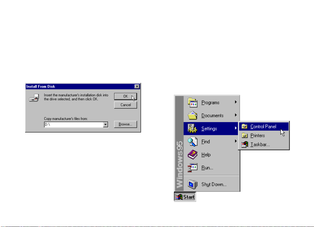
1. Click the Windows 95 Start button, point
to Settings, and then click Control Panel.
2. Double-click the System icon.
3. When the “System Properties” screen
appears, click the Device Manager tab.
4. Double-click Computer and the
“Computer Properties” screen appears.
5. Select the option at the top of the screen to
show Interrupt Requests (IRQs).
You will see the IRQs your system is currently
using. If IRQs 3, 4, 5, and 7 are being used,
you need to free an IRQ before you begin
installation. This process involves moving a
device from the IRQ you want to use to a
different (and usually higher) IRQ setting.
Please read the documentation for (or contact
the manufacturer of) the device that is currently
using the IRQ you want to use for your modem
to learn more about how to free the IRQ for
your modem.
1
Page 6
BEFORE YOU BEGIN (WINDOWS 95 USERS)
Determining Your Version of
Windows 95
Follow these steps to determine your version
of Windows 95. This information will be
important during installation.
1. Click the My Computer icon on your
desktop with the right mouse button.
2. Click Properties.
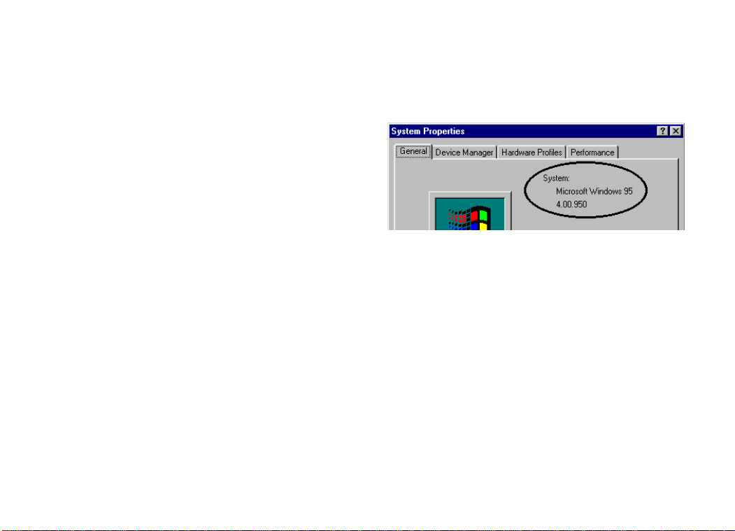
3. In the “System Properties” screen, look at
the system information under the General
tab (circled in the following screen image).
The number following the text “Microsoft
Windows 95” will end with “950”, “950a”,
or “950b”. This indicates your version of
Windows 95. Write this number on the
blank below for later reference. Then click
OK.
Windows 95 version
_________________
Upgrading to x2™ Technology
Be sure to read the section titled “U.S.
Robotics Modem Update Wizard” on page 53
for information on upgrading your 33.6
faxmodem to x2™ technology, allowing
downloads of up to 56 kbps*.
• IMPORTANT! All x2 products are capable of 56 kbps
downloads; however, due to FCC rules which restrict power
output of the service providers' modems, current download
speeds are limited to 53 kbps. Actual speeds may vary
depending on line conditions. Uploads from end users to service
providers travel at speeds up to 28.8 kbps. An x2 modem, an
analog phone line compatible with x2 technology, and an
Internet Service Provider with x2 service are necessary for these
high-speed downloads. See http://www.3com.com/x2 for details.
2
Page 7
MODEM INSTALLATION WITH WINDOWS
®
3.X
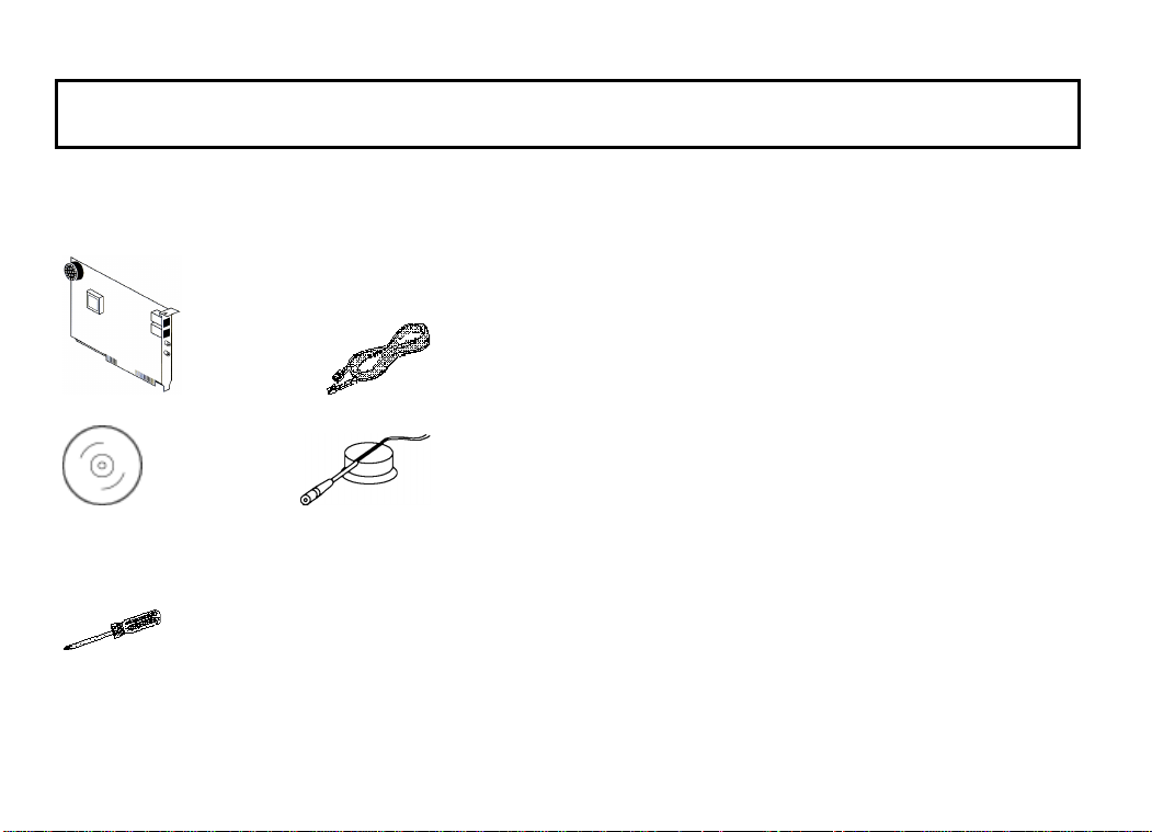
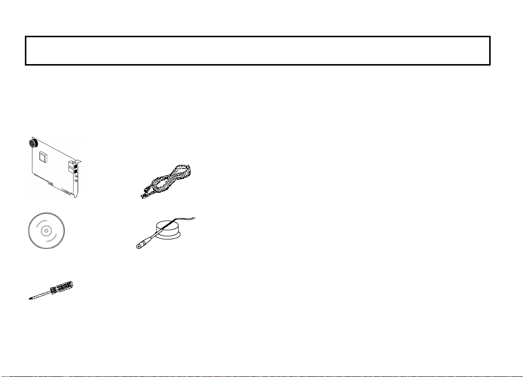
You’ll need these items from your
Sportster® modem box:
modem phone cord
Connections™ CD microphone
Plus:
a screwdriver (not included)
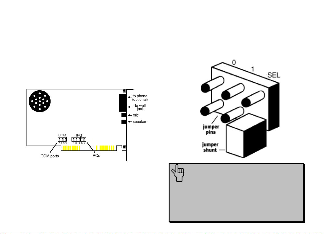
A Word about COM Ports
and IRQs
Most computer accessories — a mouse,
sound card, enhanced graphics card, scanner,
etc. — require a special connection through
which they can communicate with the
computer. For some devices, this connection is
called a communications (or COM) port. Most
computers have 1 or 2 COM ports, but they
can have up to 4. Although internal modems
do not connect to COM ports directly, they do
require a COM port setting, which is
determined by the setting on the modem’s
COM jumper pins.
Each COM port uses an interrupt request
(IRQ). An accessory uses an IRQ to get the
attention of your computer’s central
3
Page 8

MODEM INSTALLATION WITH WINDOWS 3.X
processing unit (CPU) so that the accessory
can perform a task. The computer stops what
it’s doing, depending on the priority of the
request, to help the accessory perform its task.
When two accessories share an IRQ, it’s like
two people asking different questions in unison
to a third person. Just as the person being
asked the two questions cannot understand
either request, a computer can lock up or
otherwise fail to communicate properly with
your modem when there is an IRQ conflict.
D KEY POINT: Accessories cannot
share COM ports and should not share
IRQs. When accessories try to share
settings, they will either not work
properly or not work at all. This section
of the manual will help you understand
the COM/IRQ settings on your new
Sportster modem.
3Com has set your modem to a default Plug
and Play setting geared towards Windows 95
users. In this configuration, the shunts used to
set your modem’s COM port and IRQ settings
are hanging from single jumper pins and will
not affect your modem’s settings. As a
Windows 3.x user, you need to run the
ComTest program (on the Connections CD) to
determine what settings your modem should
use.
NOTE: Some communications
software programs require a particular
setting for your modem (RapidComm,
which shipped with your modem, does
not). If you wish to use a program other
than RapidComm, now is a good time to
read that software’s manual to
determine what setting is required.
4
Page 9

MODEM INSTALLATION WITH WINDOWS 3.X
How to Use ComTest to
Determine Your Modem’s
Settings
1. Insert the Connections CD into your CD-
ROM drive.
2. In Windows’ Program Manager, click Run
on the File menu. Type d:\comtest.exe
and press ENTER. This starts ComTest,
the program that determines which COM
ports and IRQs are available for use by
your modem.
3. The screen in the next column appears
when ComTest starts.
• If there is a modem in your computer
which you are replacing with your new
Sportster modem, go to “Testing an
Installed Modem” on page 7 to
determine which COM and IRQ settings
the older modem is using.
• If a modem is not currently installed in
your computer, click Recommend
settings for a new modem.
Then click Next.
5
Page 10
MODEM INSTALLATION WITH WINDOWS 3.X
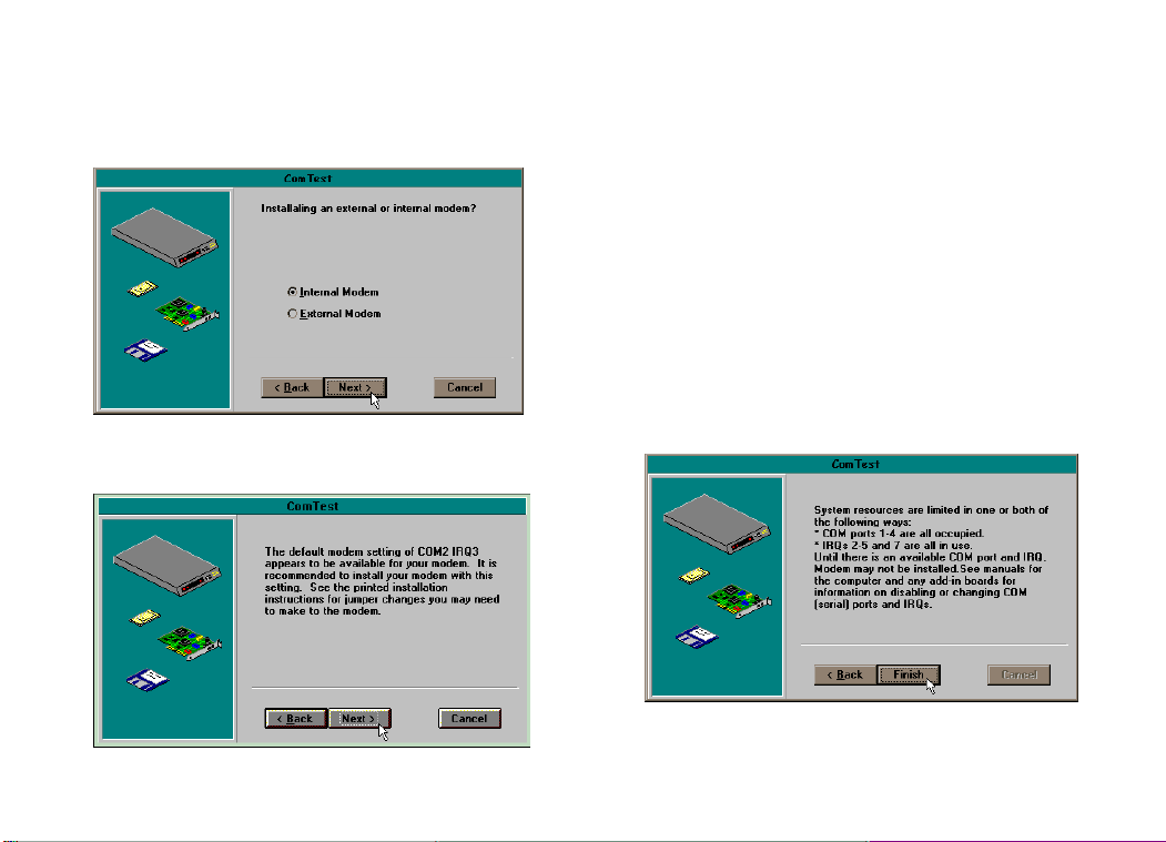
4. Click Internal Modem. Then click Next.
5. If you have a free setting, you will see a
screen like this.
COM2/IRQ3 is free in this example.
ComTest might instead recommend
COM1/IRQ4, COM3/IRQ4, or
COM4/IRQ3 for your modem.
Write down the displayed settings. You’ll
need to know these settings later. Click
Next.
If you do not have a free setting, you will
see a screen like this.
6
Page 11
MODEM INSTALLATION WITH WINDOWS 3.X
Click Finish to exit ComTest. Go to “What
to Do with ComTest’s Recommendation”
on page 8.
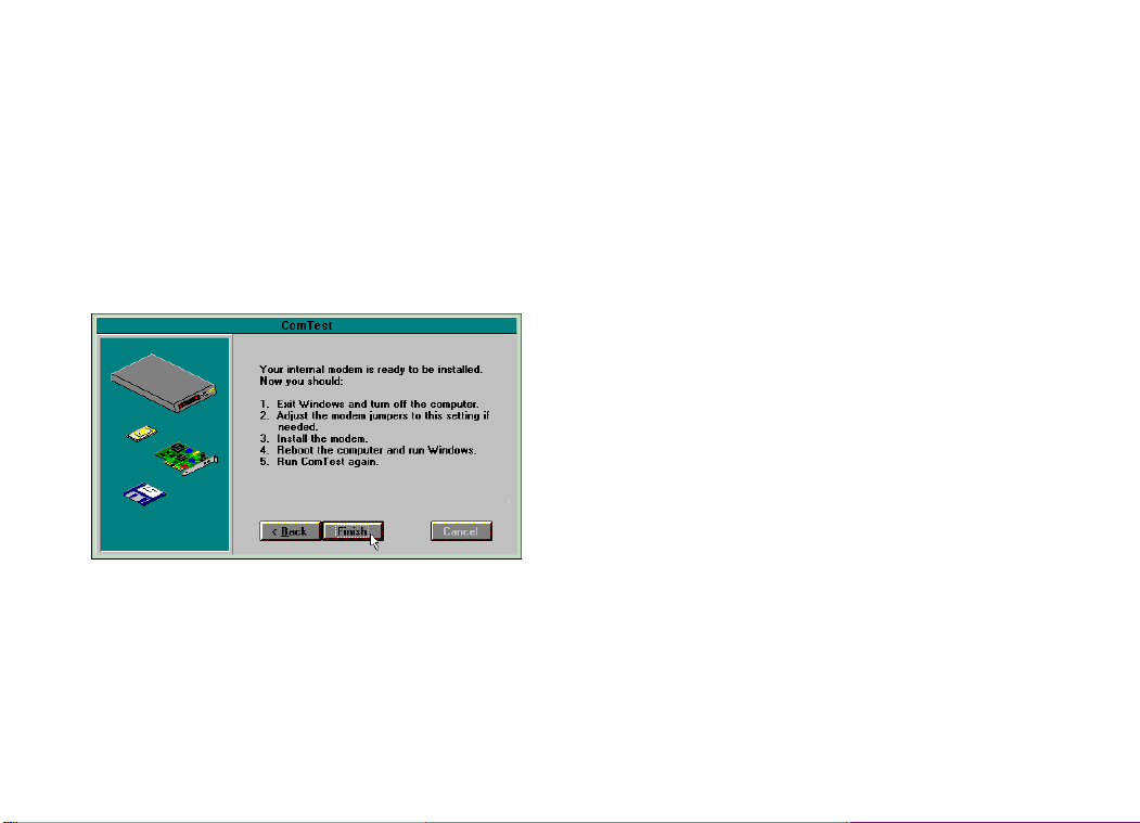
6. When you see this screen, click Finish to
exit ComTest.
Go to “What to Do with ComTest’s
Recommendation” on page 8.
Testing an Installed Modem
If there is a modem already installed in your
computer, you can determine its COM and
IRQ settings by selecting the Test an
installed modem option. Follow the
instructions on screen until you see the screen
that tells you “Testing is complete.” This screen
will also tell you which COM and IRQ settings
your present modem is using. These are the
settings you want to use for your new
Sportster modem. Write the settings down.
Turn off and unplug your computer and
remove your present modem. Go to “How to
Change the Modem’s Settings” on page 10.
7
Page 12

MODEM INSTALLATION WITH WINDOWS 3.X
What to Do with ComTest’s
Recommendation
NOTE: If your communications
software requires a modem that
ComTest does not recommend, there is
a good chance that the setting is being
used by another device in your system.
To free that setting in your system,
consult your computer’s manual. Go to
“How to Change the Modem’s Settings”
on page 10.
If ComTest recommended COM1/IRQ4
Write down “COM1” and “IRQ4” somewhere
where it will be handy during software
installation. Go to “How to Change the
Modem’s Settings” on page 10.
If ComTest recommended COM2/IRQ3
Write “COM2” and “IRQ3” somewhere
where it will be handy during software
installation. Go to “How to Change the
Modem’s Settings” on page 10.
If ComTest recommended COM3/IRQ4
or COM4/IRQ3
Do not use either of these settings. While the
COM port part of the setting is acceptable
(ComTest only recommends COM ports that
are not being used), the IRQ part of the setting
is not acceptable. When ComTest
recommends either COM3/IRQ4 or
COM4/IRQ3, the IRQ in the setting is being
used by another accessory. You could use the
suggested IRQ for the modem, but you run the
risk that the modem and/or the other accessory
sharing the IRQ might not work properly.
8
Page 13

MODEM INSTALLATION WITH WINDOWS 3.X
If you do not have a sound card, use
COM3/IRQ5. Write “COM3” and “IRQ5”
somewhere where it will be handy during
software installation. You will have to change
the settings on your modem. Go to “How to
Change the Modem’s Settings” on page 10.
If you do have a sound card, use
COM2/IRQ3. To use this setting, you have to
first disable your computer’s second serial port
(COM2). This is a pronged socket on the
back of your computer.
• Go to your computer manufacturer’s
manual.
• Find out how to disable the COM port.
• Find out which of the sockets on the back
of your computer is the second serial port.
• If you have something plugged into that
port, find out if you can plug it in
somewhere else. Any accessory plugged
into that port will not work after the port
has been disabled.
• Then return to this point in this manual to
continue.
After disabling COM2, you can use the
COM2/IRQ3 setting.
Write “COM2” and “IRQ3” somewhere
where it will be handy during software
installation and go to “How to Change the
Modem’s Settings” on page 10.
If ComTest reports that “You do not
have any available COM ports and/or
IRQs”
We recommend you disable COM1 or
COM2. When you disable one of these COM
ports, you can use it and its default IRQ for
your modem. Go to your computer
manufacturer’s manual.
9
Page 14

MODEM INSTALLATION WITH WINDOWS 3.X
• Find out which socket is COM1 and which
is COM2.
• If nothing is plugged into either port, you
may choose either of the ports to disable.
Your computer manufacturer’s manual will
tell you how to disable the COM port.
• If one port does not have anything plugged
into it, note if the port is COM1 or COM2.
This is the port you’ll want to disable for
your modem.
• If both ports are being used, you may be
able to attach one of the plugged-in
accessories elsewhere so that you can
disable its COM port. The accessory will
not work once its port is disabled.
If you’ve disabled COM1, you can now use
the COM1/IRQ4 setting. Write it down
somewhere where it will be handy during
software installation. Go to “How to Change
the Modem’s Settings” (on this page).
If you’ve disabled COM2, you can now use
the COM2/IRQ3 setting. Write the setting
down somewhere where it will be handy during
software installation.
How to Change the Modem’s
Settings
1. Always touch an unpainted metal part of
your computer (the back is usually
unpainted) to discharge static electricity
before handling the modem. Static can
damage your modem. Then take the
modem out of its plastic bag.
2. Find the COM and IRQ jumper shunts
(small black plastic pieces) on your
10
Page 15
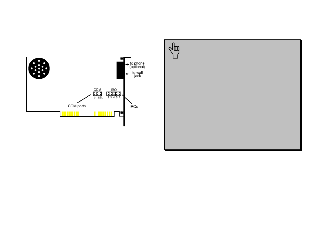
MODEM INSTALLATION WITH WINDOWS 3.X
modem’s jumper pins (see the following
diagram).
3. To change the COM port and IRQ settings,
you need to reposition the jumper shunts on
the COM port and IRQ pins. To do this, lift
the jumper shunts off the pins.
TIP: Grasp the jumper shunts with
a tweezers or needle-nosed pliers. DO
NOT grasp too firmly, as you may crush
the jumper shunts. If a jumper shunt
seems stuck, gently rock it back and
forth as you lift. Do not touch any other
part of the modem or your computer
with the tweezers/pliers. A jumper
shunt needs to be sitting on both
jumper pins in order to effectively set
the modem to the desired setting.
11
Page 16
MODEM INSTALLATION WITH WINDOWS 3.X
0 1 SEL
0 1 SEL
0 1 SEL
0 1 SEL
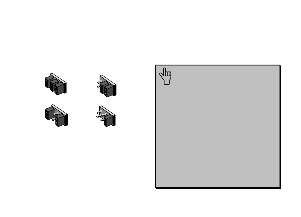
4. Move the jumper shunt to the new setting.
• The COM port setting can involve one
to three shunts. The four possible COM
port settings are as follows:
COM 1
COM 3
COM 2
COM 4
• Unlike most COM port settings, the
IRQ setting involves only one jumper
shunt. Simply move the jumper shunt to
the pins labeled with the IRQ you need.
How to Insert the Modem
into the Computer
NOTE: Before installing your
modem, write its serial number
somewhere where it will be handy
during software installation. (You’ll
find the serial number underneath the
bar code on the white sticker on the
modem and on the outside of the box
the modem came in.) If you ever need
to call our customer support
department, a customer support
representative will ask you for the
serial number. This will help him or
her identify your modem.
12
Page 17
MODEM INSTALLATION WITH WINDOWS 3.X
1. Turn off your computer and unplug it from
the electrical outlet.
2. Unplug any peripheral devices (printer,
monitor, keyboard, mouse, etc.) from the
computer.
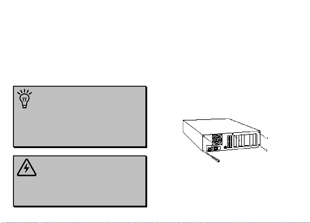
TIP: Before you unplug anything,
label the cords or make a sketch of how
things are connected. This can be
helpful when you plug things back in
later.
CAUTION: To avoid the risk of
electric shock, make sure your computer
and all peripheral devices are turned off
and unplugged.
3. Remove the screws from your computer’s
cover and then remove the cover, as shown
in the following diagrams. Your computer
may differ in appearance from these
diagrams, but the basic principle for
removing the cover should be the same.
Contact your computer manufacturer or
review their manual if you need further
instructions.
13
Page 18
MODEM INSTALLATION WITH WINDOWS 3.X
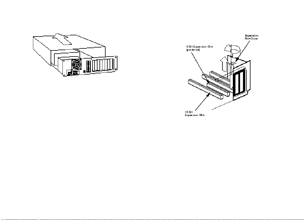
4. Find an empty ISA expansion slot at least
as long as the gold edge of your modem.
(ISA slots have black plastic grooves lined
with silver.) Unscrew and remove the
expansion slot cover (the long narrow piece
of metal that keeps dust from entering
through the opening perpendicular to the
slot). Be careful not to drop the screw into
the computer. You will need it later to
screw the modem into place.
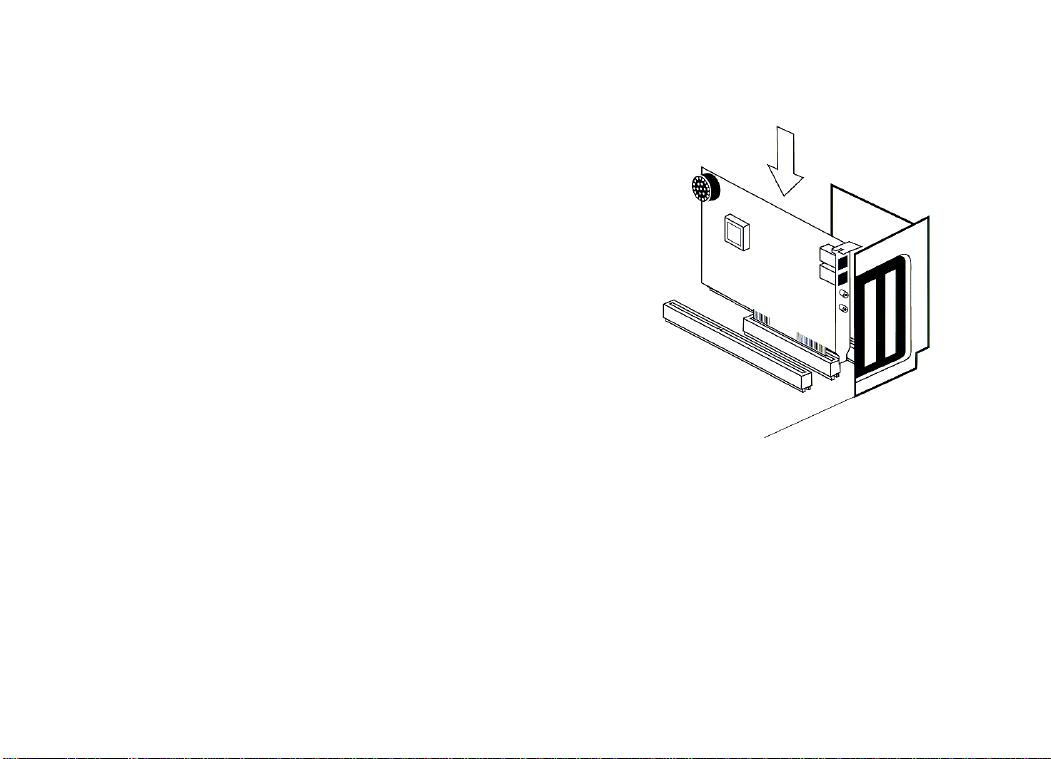
5. Holding the modem at each corner, with the
gold edge facing the slot, push the modem
down as gently as possible until it snaps into
the expansion slot. (NOTE: The drawings
show horizontally aligned expansion slots.
Some computers have vertically aligned
slots. The instructions apply to both styles.)
You need to apply a little pressure to seat
the modem properly. Sometimes a gentle
back-and-forth motion helps to fit the
14
Page 19

MODEM INSTALLATION WITH WINDOWS 3.X
modem all the way into the slot. If you feel
resistance, the modem may not be properly
lined up with the slot. Do not force it into
the slot. Remove the modem and try again.
6. Once the modem is in place, fasten it firmly
using the screw that you removed in step 4.
7. Replace the computer’s cover and fasten it
with the screws you removed in step 3.
8. If you currently have a phone plugged into
the wall jack you plan to use for the
modem, disconnect the phone’s cord from
the jack.
WARNING: The phone jack you use
must be for an ANALOG phone line (the type
found in most homes). Many office buildings
have digital phone lines. Be sure you know which
type of line you have. The modem will be
damaged if you use a digital phone line.
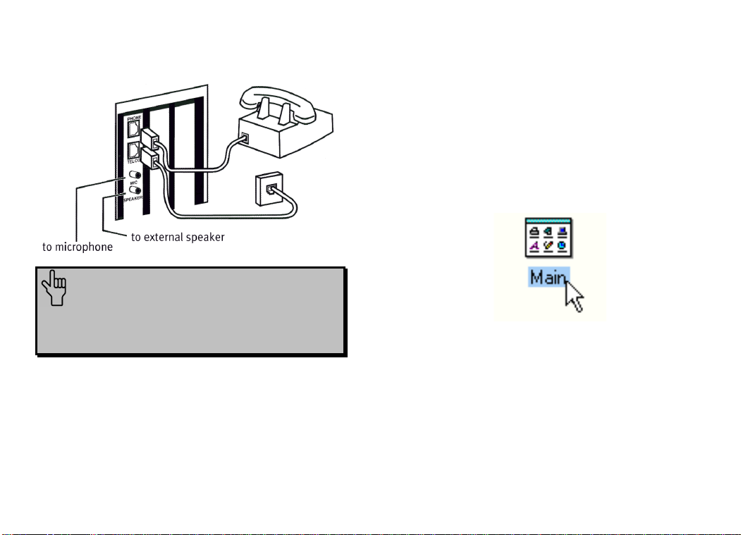
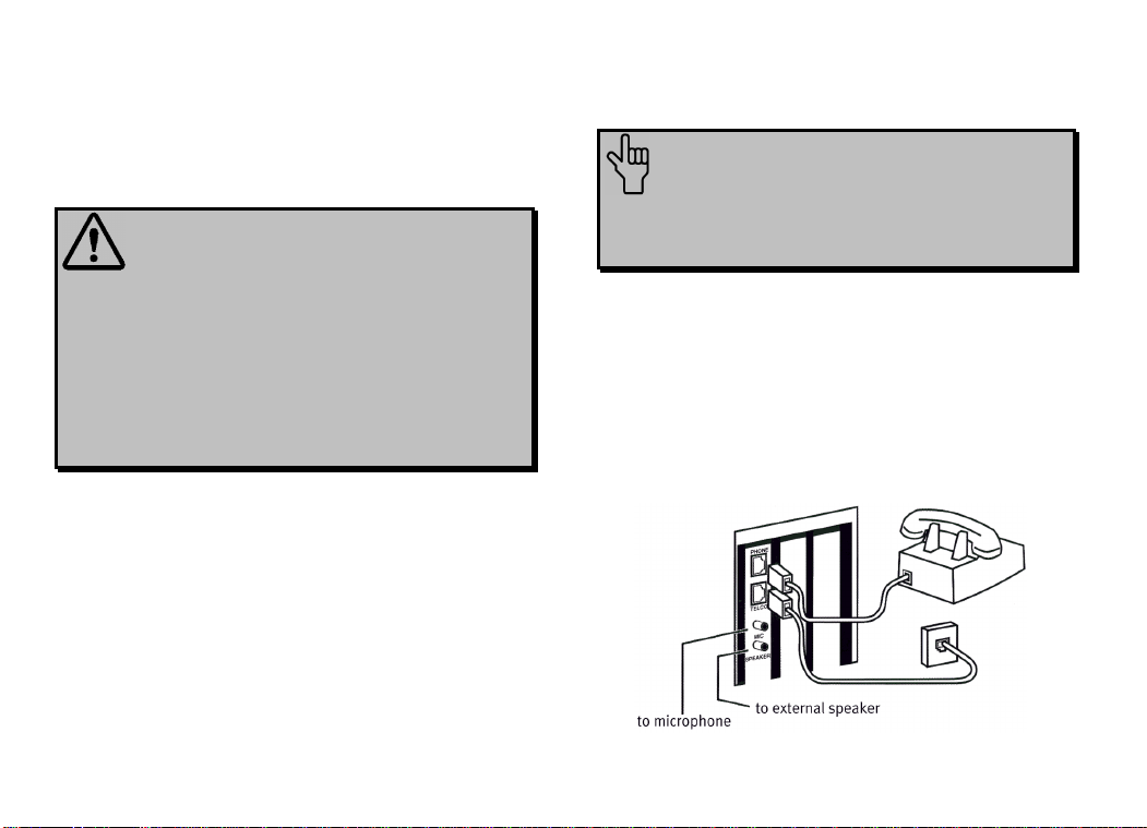
9. Plug one end of the phone cord that came
with the modem into the TELCO jack at
the rear of the modem. Plug the other end
of the cord into the wall jack.
10. If you wish to use a phone through the line
the modem uses (when the modem is not in
use), plug your phone’s cord into the
modem’s PHONE jack.
15
Page 20
MODEM INSTALLATION WITH WINDOWS 3.X
NOTE: You cannot use the modem
and a phone at the same time if they
share the same telephone line.
11. Plug the microphone included with your
modem into the MIC jack on the modem.
12. To enhance the modem’s full-duplex
speakerphone capabilities, plug a set of
powered external speakers (not included)
into the SPEAKER jack on the modem.
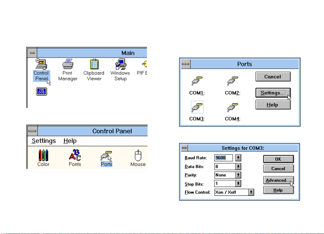
13. If you have your modem set to
COM1/IRQ4 or COM2/IRQ3, go to
“Software Installation and Testing” on page
33. If you have your modem configured to
any other setting, open Program Manager
and double-click the Main icon.
16
Page 21
MODEM INSTALLATION WITH WINDOWS 3.X
14. Double-click the Control Panel icon.
15. Double-click the Ports icon.
16. If it’s not already selected, click the COM
port for your modem. Then click Settings.
17. Click Advanced.
17
Page 22
MODEM INSTALLATION WITH WINDOWS 3.X
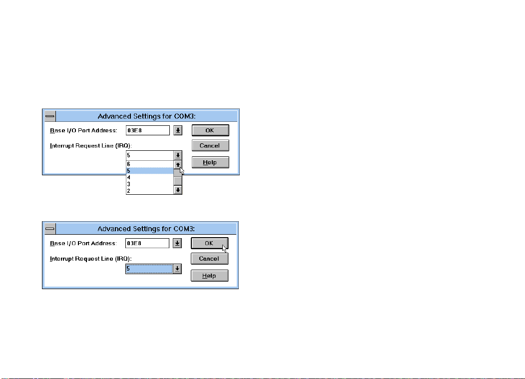
18. In the Interrupt Request Line (IRQ)
box, select the IRQ that ComTest
recommended.
19. Click OK.
You will see a brief series of screens after the
preceding screen. Click OK on each screen
until you see a screen with a Close button.
Click Close to exit Program Manager.
You are now ready to install the software on
the Connections CD-ROM (included with
your Sportster modem). Turn to “Software
Installation and Testing” (page 33) for detailed
information about installing the software,
registering the modem, and trying out your
modem by faxing U.S. Robotics.
18
Page 23
MODEM INSTALLATION WITH WINDOWS
®
95
You will need these items from your
Sportster™ modem box:
modem phone cord
Connections™ CD microphone
Plus:
a screwdriver (not included)
Since your new Sportster is a “Plug and Play”
device, Windows 95 may be able to detect
your modem automatically after you plug it into
your computer. The operating system should
do all the work of recognizing the modem for
you.
How to Prepare for Plug and
Play Installation
1. Touch an unpainted metal part of your
computer (the back is usually unpainted) to
discharge static electricity. Static can
damage your modem.
2. Take the modem out of its plastic bag.
19
Page 24
MODEM INSTALLATION WITH WINDOWS 95
3. Find the jumper shunts (small black plastic
pieces) on the COM port and IRQ jumper
pins on your modem. They should be in
roughly the area indicated in the following
illustration.
When doing a “Plug and Play” installation,
the jumper shunts should be placed so that
they are hanging from single jumper pins
rather than on pairs of pins. Move your
20
jumper shunts so they are hanging as in the
following diagram.
NOTE: If you need to move the jumper
shunts, grasp them with a tweezers or a needlenosed pliers. DO NOT grasp too firmly, however,
or you may crush the jumper shunts. If a jumper
shunt seems stuck, try gently rocking it back and
forth as you lift.
Page 25

MODEM INSTALLATION WITH WINDOWS 95
How to Insert the Modem
into the Computer
NOTE: Before installing your
modem, write down its serial number.
(You’ll find the serial number
underneath the bar code on the white
sticker on the modem and on the
outside of the box the modem came
in.) If you ever need to call our
customer support department, a
customer support representative will
ask you for the serial number. This
will help him or her identify your
Sportster modem.
1. Turn off your computer and unplug it from
the electrical outlet.
2. Unplug any peripheral devices (printer,
monitor, keyboard, mouse, etc.) from the
computer.
TIP: Before you unplug any cords,
label them or make a sketch of how
they are connected. This can be helpful
when you plug them back in later.
CAUTION: To avoid risk of
electric shock, make sure your computer
and all peripheral devices are turned off
and unplugged from electrical outlets.
3. Remove the screws from your computer’s
cover and then remove the cover, as shown
21
Page 26

MODEM INSTALLATION WITH WINDOWS 95
in the following diagrams. Your computer
may differ in appearance from these
diagrams, but the basic principle for
removing the cover should be the same.
Refer to your computer manufacturer’s
manual if you need further instructions.
4. Find an empty ISA expansion slot that’s at
least as long as the gold edge of your
modem. (ISA slots are black plastic
grooves lined with metal.) Unscrew and
remove the expansion slot cover (the long
narrow piece of metal that keeps dust from
entering through the opening perpendicular
to the slot).
22
Page 27
MODEM INSTALLATION WITH WINDOWS 95
5. Holding the modem at each corner, with the
gold edge facing the slot, push the modem
down as gently as possible until it snaps into
the expansion slot. (NOTE: The following
diagram shows horizontally aligned
expansion slots. Some computers have
vertically aligned slots. The instructions
apply to both styles.)
You need to apply a little pressure to seat
the modem properly. Sometimes a gentle
back-and-forth motion helps fit the modem
all the way into the slot. If you feel
resistance, the modem may not be properly
lined up with the slot. Do not force it into
the slot. Remove the modem and try again.
6. Once the modem is in the slot, fasten the
modem firmly into place using the screw
that you removed in step 4.
7. Replace the computer’s cover and fasten it
with the screws you removed in step 3.
8. Locate the wall jack you plan to use for the
modem. If you have a phone plugged into
23
Page 28
MODEM INSTALLATION WITH WINDOWS 95
this jack, disconnect the telephone cord
from the jack.
WARNING: The phone jack you
use must be for an ANALOG phone line
(the type found in most homes). Many
office buildings have digital phone
lines. Be sure you know which type of
line you have. The modem will be
damaged if you use a digital phone line.
9. Plug one end of the phone cord included
with the modem into the TELCO jack at
the rear of the modem. Plug the other end
of the cable into the wall jack.
10. If you wish to use a phone through the line
the modem uses (when the modem is not in
use), plug your phone’s cord into the
modem’s PHONE jack.
NOTE: You cannot use the modem
and a phone at the same time if they
share the same telephone line.
11. Plug the microphone included with your
modem into the MIC jack on the modem.
12. To enhance the modem’s full-duplex
speakerphone capabilities, plug a set of
powered external speakers (not included)
into the SPEAKER jack on the modem.
24
Page 29
MODEM INSTALLATION WITH WINDOWS 95
13. Plug the power cords, cables, and
peripherals back into the computer and turn
on the computer.
Installing the Modem
Drivers
NOTE: If you wrote “950b” on
page 2 of this User’s Guide, go to
“Installing Modem Drivers with
Windows 95 Version 950b” on page 29.
Otherwise, follow these instructions.
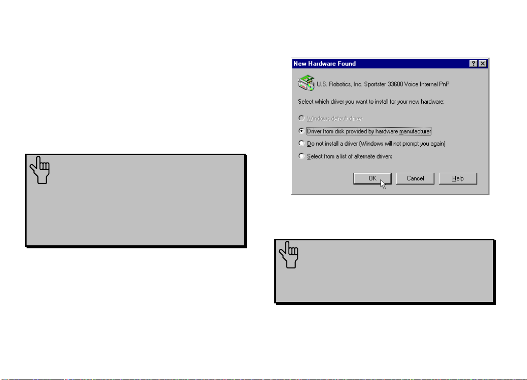
Click Driver from disk provided by
hardware manufacturer. Then click OK.
Installing Modem Drivers with
Windows 95 Versions 950 and 950a
1. When Windows 95 restarts, it should
detect the modem. If it does, you will see
the following screen.
NOTE: If this screen does not
appear, go to the section titled “When
Plug and Play Fails” on page 95.
25
Page 30
MODEM INSTALLATION WITH WINDOWS 95
2. When you see this screen, insert the
Connections CD into your CD-ROM drive
and type D:\ to replace the A:\. (NOTE: If
your CD-ROM drive has a different letter
name, type that letter instead of D.)
Click OK. Windows will load the modem’s
drivers.
3. Once Windows finishes loading the
information from the CD-ROM, you should
verify that the modem installation was a
success. When your desktop returns, click
the Windows Start button and point to
Settings. Then click Control Panel.
26
Page 31

MODEM INSTALLATION WITH WINDOWS 95
4. Double-click the Modems icon (circled in
the screen image below).
5. In the “Modems Properties” screen, you
should see “Sportster 33600 Voice Internal
PnP” listed.
27
Page 32

MODEM INSTALLATION WITH WINDOWS 95
This means the installation was a success.
Click OK.
NOTE: If you do not see your
modem listed in the preceding
screen, the Plug and Play installation
was unsuccessful. Please refer to
“When Plug and Play Fails” on page
95.
6. Next, click the Diagnostics tab at the top
of the “Modems Properties” screen. Write
down the COM setting for your modem.
(NOTE: Your screen may show a different
setting than that shown in the following
screen.) You will need to know this setting
when you install RapidComm Voice.
Turn to “Software Installation and Testing”
(page 33) for detailed information about
installing RapidComm Voice, registering the
modem, and trying out your modem by
faxing U.S. Robotics.
28
Page 33

MODEM INSTALLATION WITH WINDOWS 95
Installing Modem Drivers with
Windows 95 Version 950b
1. When Windows restarts, it should detect
the modem (see following screen image).
Insert the Connections CD and click Next.
NOTE: If this screen does not
appear, go to the section titled “When
Plug and Play Fails” on page 95.
2. When you see the following screen, click
Finish.
29
Page 34

MODEM INSTALLATION WITH WINDOWS 95
3. Once Windows 95 has installed the
modem’s drivers, you will see the following
screen. This screen tells you which
communications port your modem is
installed to. (NOTE: Your screen may
show a different COM port.) Make a note
of the COM port setting. You will need this
information later when you installing the
software on the CD-ROM. Remove the
CD from your CD-ROM drive and click
OK. Windows will restart.
4. Once Windows restarts, you should verify
that the modem installation was a success.
When your desktop returns, click the
Windows Start button and point to
Settings. Then click Control Panel.
30
Page 35

MODEM INSTALLATION WITH WINDOWS 95
5. Double-click the Modems icon (circled in
the screen image below).
6. In the “Modems Properties” screen, you
should see “Sportster 33600 Voice Internal
PnP” listed.
31
Page 36

MODEM INSTALLATION WITH WINDOWS 95
This means the installation was a success.
Click OK.
NOTE: If you do not see your
modem listed in the preceding
screen, the Plug and Play installation
was unsuccessful. Please refer to
“When Plug and Play Fails” on page
95.
7. Next, click the Diagnostics tab at the top
of the “Modems Properties” screen. Write
down the COM setting for your modem.
(NOTE: Your screen may show a different
setting than that shown in the following
screen.) You will need to know this setting
when you install RapidComm Voice.
Turn to “Software Installation and Testing”
(page 33) for detailed information about
installing RapidComm Voice, registering the
modem, and trying out your modem by
faxing U.S. Robotics.
32
Page 37

SOFTWARE INSTALLATION AND TESTING
Software Installation and
Registration Using the
Setup Wizard
This section guides you through the U.S.
Robotics Setup Wizard, the Connections
CD-ROM interface, and the installation of
RapidComm™ Voice fax/data/voice software.
It also shows you how to register and test your
new Sportster modem.
RapidComm Voice fax/data/voice software
simplifies sending and receiving faxes directly
from your computer desktop. You can build
your own fax directory, send faxes to specified
groups of phone numbers, request individual
cover pages when necessary, and send
individual faxes without exiting your word
processing program.
™
Additionally, RapidComm Voice software lets
you connect to BBSs and other online data
providers. Take advantage of this access to
enter a new world of information and
entertainment.
NOTE: The following instructions
apply to Windows 3.x and Windows 95
users. However, only Windows 95
screens are shown.
NOTE: If you have an older
version of RapidComm Voice software
installed on your system, uninstall it
before continuing.
33
Page 38

SOFTWARE INSTALLATION AND TESTING
1. From the Windows 95 desktop, click the
Start button and then click Run.
2. In the text box, type D:\setup.exe. (If your
CD-ROM drive has a letter name other
than D, type that letter in place of D.)
3. You will briefly see a screen that looks like
this.
4. When you are asked if you wish to run the
Setup Wizard, click Yes.
34
Page 39
SOFTWARE INSTALLATION AND TESTING
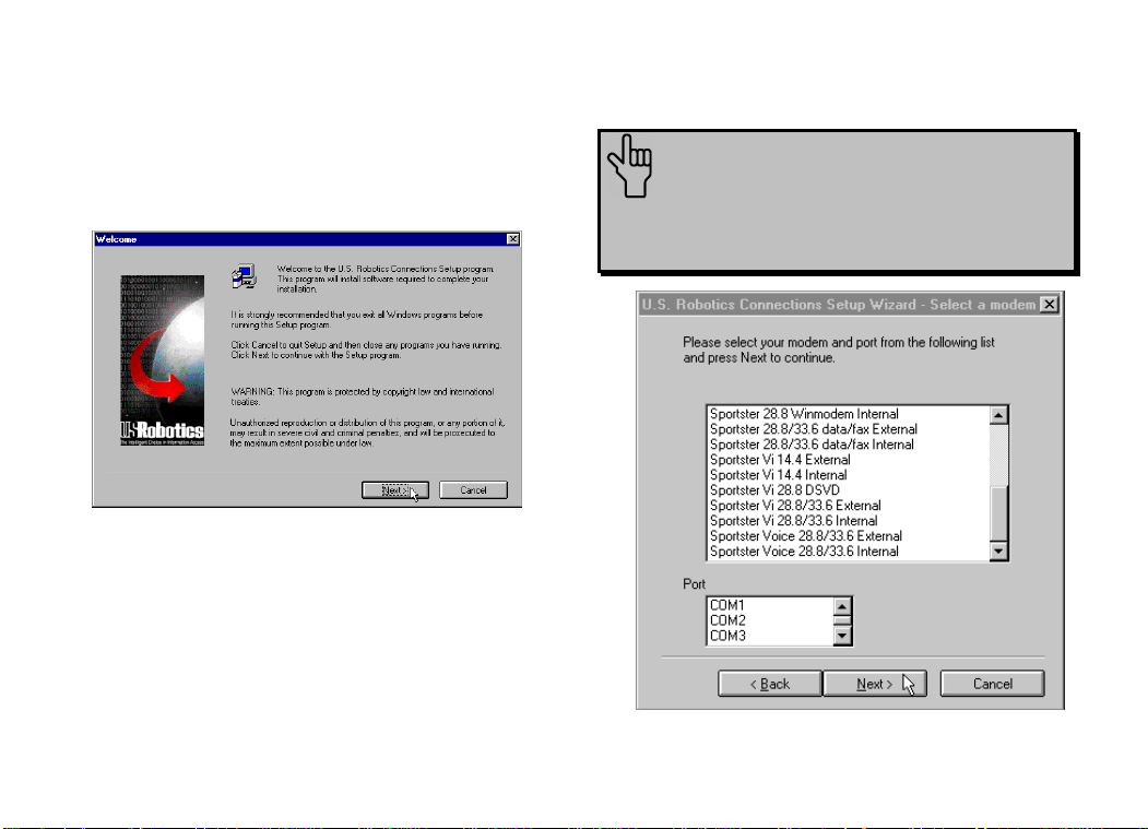
5. This is the Setup Wizard’s “Welcome”
screen. After reading the screen, click
Next.
6. When you see the following screen, select
your modem from the list and select the
correct COM port setting in the Port box.
Then click Next.
NOTE: Check the COM port
setting against the setting you wrote
down during the hardware installation.
35
Page 40

SOFTWARE INSTALLATION AND TESTING
7. When you see the next two screens, fill in
the blank boxes with the appropriate
information, using the TAB key to move
between fields. Click Next on each screen
when you have filled in all of the necessary
information.
8. You will see the following screen as the
Setup Wizard creates a U.S. Robotics
Connections program group.
9. Next, the Setup Wizard looks for Netscape
Navigator on your system.
If the Setup Wizard does not find Netscape
Navigator, it searches for Microsoft’s
Internet Explorer. If the Setup Wizard does
not find Internet Explorer, it will
automatically install the application later in
the Setup Wizard process.
36
Page 41

SOFTWARE INSTALLATION AND TESTING
10. The next screen introduces the U.S.
Robotics Registration Wizard. After you
read the screen, click Next. Read through
each of the next two screens and verify or
correct the information you typed earlier.
Click Next on each screen to move on.
37
Page 42

SOFTWARE INSTALLATION AND TESTING
11. When you see this screen, you are ready to
register your new modem. Click By
Modem. We recommend you choose the
By Modem option because it’s a great
way to verify that your Sportster modem is
correctly installed.
12. When you see this screen…
• If you need to dial a prefix (such as 9) to
make a call outside your building, type
the prefix before the 1 in the Prefix box
and then click Dial. If the modem still
does not dial the number properly, you
may need to insert a comma between the
prefix and the 1 to force the modem to
pause.
38
Page 43

SOFTWARE INSTALLATION AND TESTING
• If you do not need to dial a prefix,
simply click Dial.
13. You will see a screen indicating that the
registration information has been sent (see
circled text in the screen below).
14. The next screen indicates that the Setup
Wizard is finished. Click OK to launch the
Connections CD-ROM.
NOTE: If the Setup Wizard detected
Internet Explorer on your system during the
setup process, your computer will launch
the Connections CD-ROM when you click
OK. Continue at step 15.
If the Setup Wizard DID NOT detect
Internet Explorer on your system earlier in
the setup process, it will launch the Internet
Explorer installation utility after you click
OK. When you see the following screen,
click Install Internet Explorer and follow
the on-screen instructions to complete the
installation of the software.
39
Page 44

SOFTWARE INSTALLATION AND TESTING
At the end of the installation process, you
will see the following screen. Click Yes.
Windows 95 users: Windows will restart
and the Connections CD will launch
automatically upon restart.
Windows 3.x users: Windows will
restart. When your desktop reappears, you
will see a Connections icon (shown below)
in the Connections program group.
Double-click the icon to launch the CD.
40
Page 45

SOFTWARE INSTALLATION AND TESTING
15. When the main Connections menu appears,
click Business & Productivity on the
menu on the left hand side of the screen
(circled below).
16. On the Business & Productivity menu is
a RapidComm Voice button (circled in the
following screen shot). RapidComm Voice
is the fax/data/voice software you can use
to send faxes directly from your desktop,
transfer files electronically, set up multiple
voice mail boxes, or dial into a BBS. Click
RapidComm Voice.
41
Page 46

SOFTWARE INSTALLATION AND TESTING
17. The next screen contains another menu on
the right hand side of the screen. Included
on the menu is a Learn More & Get
Software button (circled in the screen
image below). Click this button.
18. The next screen displays information about
the RapidComm Voice software. When
you are ready to install the RapidComm
Voice software, click Install (circled in the
lower left hand corner of the following
screen image).
42
Page 47

SOFTWARE INSTALLATION AND TESTING
NOTE: If you are using Netscape
Navigator to view your Connections CDROM, you may be asked to save the
application’s installer to your computer
when you click the Install button. Note
the installer’s file name and its location
on your computer. To run the installer
or demo, find the file on your computer
and double-click it. The installer will
start.
19. The next screen is the first of the
“RapidComm Voice Setup” screens. When
this screen appears, make sure the location
shown in the text box is where you would
like the files copied to and then click
Install. If you wish to copy the
RapidComm Voice files to a different
directory, type that location in the text box
before clicking Install.
20. You will see this screen as files are copied.
43
Page 48

SOFTWARE INSTALLATION AND TESTING
21. When you see this screen, click either Yes or No.
• If you click Yes, every document you print will be
treated as a fax unless you change the printer
selection in the program from which you are
printing.
• If you click No, RapidComm Voice will not be
selected as the default printer. When you want to
send a fax, you must select RapidComm Voice as
the printer in the program from which you are
printing.
This screen marks the end of the
RapidComm Voice installation. Click
OK to return the Connections.
23. Click Exit (circled in the following screen
image).
44
Page 49

SOFTWARE INSTALLATION AND TESTING
24. Restart Windows by clicking the Windows
Start button and pointing to Shut Down.
Click Restart the Computer? on the
“Shut Down Windows” screen. Then click
Yes.
25. When your desktop appears, click
Windows Start. Point to Programs. Then
point to RapidComm Voice.
26. The following is the first “RapidComm
Voice Setup Wizard” screen. After you
read the screen, click Next.
45
Page 50

SOFTWARE INSTALLATION AND TESTING
27. When you see this screen, verify the
information shown and then fill in the Data
box (if you have a third phone number just
for your modem) and the Local Area
Code box. Then click Next.
28. After you verify the information on this
screen, click Next.
46
Page 51

SOFTWARE INSTALLATION AND TESTING
29. Select the correct modem in the text box
on the following screen. Then click Next.
30. The next screen allows you to select single
or multiple mailboxes for your personal
voice mail system. Click Single or
Multiple and then click Next.
47
Page 52

SOFTWARE INSTALLATION AND TESTING
31. When you see this screen…
• If you want the RapidComm Voice
program to launch at Windows startup,
select the box to the left of Run
RapidComm Voice at Windows
startup. A check will appear in the box.
Then click Finish.
48
• If you do not want RapidComm Voice
to start every time you start Windows,
simply click Finish.
32. You will see this screen.
This is the main RapidComm Voice screen.
To send your first fax, keep this screen
open. (After this initial run, RapidComm
Voice will not need to be running in order to
send a fax.)
Sending Your First Fax
Using RapidComm Voice software, you can
send and receive faxes directly from your
computer and eliminate the need for a fax
machine. Once you learn the basics of sending
faxes, you can learn more involved fax
Page 53

SOFTWARE INSTALLATION AND TESTING
functions, such as sending documents to
groups of numbers at assigned times and how
to transfer data files. These more advanced
functions are explained in the electronic
RapidComm Voice manual on your
Connections CD. This chapter will walk you
through sending your first fax.
1. Open an application in which you can
create documents that you might want to
fax (e.g., a word processing application).
Create a document containing only a
sentence or two. Name the document
tester. Keep the document open.
2. From the File menu, click Print.
3. Select RapidComm Voice as the printer.
This can be changed in most Windows
applications in the Print or Printer Setup
dialog box.
4. Click OK or Print (whichever button you
click in your application to indicate that you
are ready to print) in the Print dialog box.
49
Page 54

SOFTWARE INSTALLATION AND TESTING
5. When you see the following screen, fill in
the necessary information in the text boxes.
For testing purposes, send your “tester”
document to the 3Com fax number, 847676-3559.
NOTE: If you need to enter a
prefix (such as 9) to dial a number
outside your building, type the prefix
before the fax number in the Fax
number field.
When you finish, click Send Fax.
6. You will see a series of screens as the fax is
being transmitted. When the fax has been
successfully transmitted, you will see a
screen that looks like this.
50
Page 55

SOFTWARE INSTALLATION AND TESTING
Congratulations —you are
now ready to start using
your Sportster modem!
Go to the electronic RapidComm Voice
manual on your Connections CD for more
detailed instructions on sending faxes and other
things you can do using your Sportster modem
and RapidComm Voice software.
51
Page 56

INSTALLING OTHER FAX/DATA SOFTWARE
Your modem was designed for and tested
using a wide range of communications software
packages. This section will guide you through
some of the details you may need to know
when installing communications software
packages other than RapidComm Voice
(included on the Connections CD-ROM).
Type of Modem
Most communications software programs will
ask you to select the type of modem you are
using. Select a U.S. Robotics Sportster high
speed modem. If that selection is not listed,
pick Courier Dual Standard, V.32bis, or V.
34.
52
Initialization String
For hardware flow control, a fixed serial port
rate, and full result codes, type AT&F1 and
then press ENTER. If you must use software
flow control, type AT&F2 and then press
ENTER.
Flow Control
For hardware flow control (highly
recommended), select RTS/CTS. For
software flow control, select XON/XOFF.
You may need to disable the flow control
(hardware or software) that you are not using.
Page 57

U.S. ROBOTICS MODEM UPDATE WIZARD
Your Connections™ CD-ROM includes the U.S.
Robotics Modem Update Wizard. This software
is designed to quickly update your modem,
whether to a newer version of its current code or
to 3Com’s revolutionary new x2™ technology.
You can update your modem in any of the
following 3 ways:
NOTE: Complete the instructions in
the Software Installation and Testing
section of this manual before installing
the Modem Update Wizard.
33.6 K to 33.6 K (update) = FREE
33.6 K to 56 K (upgrade) = $FEE
56 K to 56 K (update) = FREE
* Fee for upgrades is subject to change.
NOTE: You can obtain this software
from our BBS (847-982-5092) or from our
World Wide Web page (www.3com.com) if
you do not have a Connections CD-ROM.
*
NOTE: These instructions pertain to
Windows 3.x and Windows 95. However,
only Windows 95 screen shots are shown
unless the process for Windows 3.x users
differ significantly.
Installation
1. Insert the Connections CD-ROM into your
CD-ROM drive.
53
Page 58

U.S. ROBOTICS MODEM UPDATE WIZARD
2. Click the Windows Start menu and point to
Programs. Point to U.S. Robotics
Connections. Then click Connections.
NOTE: Windows 3.x users launch the
CD-ROM by clicking the Connections icon
in the Connections program group.
54
3. From the main Connections menu, click
Customer Support (circled in the following
screen shot).
Page 59

U.S. ROBOTICS MODEM UPDATE WIZARD
4. When the Customer Support menu appears,
click Modem Update Wizard (circled in the
following screen shot).
5. Next, click Learn More & Get Software
(circled in the following screen shot).
55
Page 60

U.S. ROBOTICS MODEM UPDATE WIZARD
6. In the following screen, click Install (circled
below).
56
7. This launches the U.S. Robotics Modem
Update Wizard Installer. The screen that
follows is the welcome screen for the installer.
After you read this screen, click Next.
Page 61

U.S. ROBOTICS MODEM UPDATE WIZARD
8. The next screen indicates where the installer
will store the files for the Update Wizard. If the
indicated location is acceptable, click Next.
Otherwise, click Browse to find an acceptable
directory.
9. You will see the following screen for a moment
as the installer creates the Modem Update
Wizard program group.
10. This screen indicates that the setup is
complete. Click OK.
57
Page 62

U.S. ROBOTICS MODEM UPDATE WIZARD
Operation
1. Click the Windows Start button. Point to
Programs. Then point to U.S. Robotics
Modem Update Wizard. Finally, click
Modem Update Wizard.
2. After you read the “Welcome” screen, click
Next.
58
3. This brings up the license agreement. After
reading the license agreement, click Accept to
continue.
Page 63

U.S. ROBOTICS MODEM UPDATE WIZARD
4. The software will now detect any modems
installed on your system. When the detection
phase finishes, you will see the following screen
(the modems shown on your screen may
differ). Click the modem you wish to upgrade
and then click Next to continue.
5. The program will now determine if the selected
modem is software upgradable.
Non-Upgradable Modems
If your modem IS NOT software upgradable,
the program will display the following screen.
• Click U.S. Robotics if your modem is a
U.S. Robotics modem to learn more about
your upgrade options.
59
Page 64

U.S. ROBOTICS MODEM UPDATE WIZARD
• Click Other to learn more about how to
purchase a U.S. Robotics x2 modem.
Upgradable Modems
If the modem IS software upgradable, you will
see the following screen.
Click Dial U.S. Robotics (which should be
the default selection) in the pull-down menu.
Click Upgrade to x2 Technology if you wish
60
to upgrade a 33.6 kbps modem to 56 kbps
code or click Update my modem’s code to
update your modem with the most recent
version of its original code. Then click Next.
6. The next screen you will see is the order
information screen. Users who are purchasing
a 56K upgrade will see a screen that includes a
credit card information query. Users who are
updating their modem’s code will see a
personal information query screen. Fill in the
screen with the appropriate information and
then click Next.
Page 65

U.S. ROBOTICS MODEM UPDATE WIZARD
7. The following screen dials the U.S. Robotics
Update Server. Click Tone or Pulse dialing as
necessary. If you normally dial a prefix (such
as 9) to dial out on your phone line, type that
prefix before the 1 in the Prefix box. Then
click Dial.
NOTE: Your screen may show a
different number in the Number field.
61
Page 66

U.S. ROBOTICS MODEM UPDATE WIZARD
8. Once connected, the server will compare
available upgrades with the current code in
your modem. If they differ, the server will
automatically initiate the download procedure.
NOTE: Users purchasing a 56K upgrade are
asked if the charge is acceptable (see the following
screen image). Unless you have already been
charged for an upgrade, click Yes to continue. If you
have already been through this process once before,
DO NOT click Yes. Click No and call Customer
Support at 847-982-5151. (The price of the upgrade
is subject to change and includes applicable taxes.)
NOTE: If you do not have the most up
to date .inf file for your modem (the file
that helps Windows correctly identify your
modem), you will see the following screen
as the Modem Update Wizard
automatically downloads the file.
62
Page 67

U.S. ROBOTICS MODEM UPDATE WIZARD
9. You will see this screen as the Wizard
downloads the file for your modem.
10. When the download is complete, the modem
disconnects from the server. The words
“Downloading file…” change to “Upgrading
…” or “Updating …”, depending on whether
you are upgrading or updating your modem. A
new progress bar appears. This indicates that
your modem’s code is being updated.
WARNING! To avoid the risk of
damaging your modem, DO NOT turn off
the modem while it is being updated.
11. When updating is complete, the progress bar
will be full and an “Update/Upgrade
Complete” message appears. Click Next.
63
Page 68

U.S. ROBOTICS MODEM UPDATE WIZARD
12. You will see a “Congratulations!” screen.
Click Details.
64
13. Click OK once you verify that the process was
a success. When you return to the
“Congratulations!” screen, click Finished.
Congratulations!
Enjoy the benefits of your updated Sportster
modem!
Page 69

USING MODEM STATION
What Does Modem Station
Do?
♦ Modem Station provides a simple to use
interface that makes communicating with
your modem even easier.
♦ Modem Station allows you to point and
click your way through configuration.
♦ Modem Station can automatically detect
your modem and provide you with all the
technical information you need, whenever
you need it!
Why Modem Station?
♦ Modem commands can be confusing and
difficult to memorize.
♦ Communications software often needs
technical information about your modem.
♦ You may want to “tweak” your modem for
optimum performance.
♦ You’d rather be surfing the Internet.
Installing Modem Station
If you did not install Modem Station when you
first installed the Connections CD, please
follow these instructions.
1. Insert the Connections CD into your CD-
ROM drive.
2. Double-click the My Computer icon on
your desktop.
3. Double-click the CD-ROM icon.
4. Double-click the USR Tools folder.
5. Double-click the umssetup icon.
65
Page 70

USING MODEM STATION
6. You will be asked whether you wish to
install Modem Station. Click Yes.
7. Wait a few moments for the Installation
Wizard to load.
8. After reading the information on the
“Welcome” screen, click Next.
9. When you see this screen, click Next to
accept the default directory or click
Browse to change directories.
66
Page 71

USING MODEM STATION
10. Click Next on the following screen to
accept the default program folder. You can
place Modem Station in an existing folder
by selecting one from the list.
11. When you see the following screen, click
Finish to complete the installation.
If this is the first time you’ve installed
Modem Station, you may be asked to
restart your computer.
67
Page 72

USING MODEM STATION
Starting Modem Station
1. If you didn’t start Modem Station from the
Setup program, please start it now.
2. Click Windows Start button and then point
to Programs. Click U.S. Robotics
Modem Station (or the folder you
selected during installation).
3. Click the Modem Station icon. This brings
up the main menu.
68
Page 73

USING MODEM STATION
The main menu gives you direct access to
the following options:
♦ DETECT NEW MODEMS
♦ TERMINAL
♦ MODEM CONFIGURATOR
♦ ABOUT
♦ CONTACT/SUPPORT
DETECT NEW MODEMS
This option detects US Robotics modems
installed on your system and shows what
COM port they are using. Click this option if
you are running Modem Station for the first
time, if you are changing modems, or if you
simply need to know what port your modem is
using.
TERMINAL
Terminal allows you to send commands
directly to your modem and displays the
responses. You can use Terminal to dial up
BBSs. In addition, you can configure your
modem using Terminal. However, it is much
easier to use the Modem Configurator.
MODEM CONFIGURATOR
Modem Configurator provides an easy-to-use
interface for entering hard to remember
commands. Use Modem Configurator for
troubleshooting, initial configuration, and tuning
your modem for optimum performance. Using
the options available in Modem Configurator,
you can control nearly every aspect of your
modem’s performance. We will discuss
Modem Configurator’s options in more detail
in later sections.
ABOUT
The About option provides copyright and
version information.
69
Page 74

USING MODEM STATION
CONTACT/SUPPORT
This option details how to get in touch with
U.S. Robotics.
TIP: For your convenience, we
provide many on-line support
avenues. For specific questions,
our fax-on-demand service is a
good place to start. You can
download FAQs, software, and help
files from our Web sites and BBS,
or receive individualized support
via support@usr.com. Type 0000 (4
zeroes) in the subject line of your
e-mail.
Using Detect New Modems
1. Click Detect New Modems to bring up
the following screen.
The screen consists of four columns, one for
each possible COM port on a PC. You
can scan a specific port(s) by selecting the
checkbox for that port.
70
Page 75

USING MODEM STATION
2. Click Scan to have Modem Station check
for installed modems. This may take a few
moments.
3. When the scan finishes, you will see the
following display. Your display may differ
depending on the type and number of
modems installed.
If your modem is installed and configured
correctly, Modem Station will find the
modem and display make and model
information under the assigned port. All
currently active ports should display “Port
OK” under the heading. If a port displays a
“Port Error”, it usually means that the port is
disabled in system setup.
NOTE: Different systems and
BIOSes use different methods of
disabling COM ports. As a result,
we cannot provide support for
enabling COM ports. Please refer
to your system’s documentation or
contact the manufacturer of your
system for further information.
71
Page 76

USING MODEM STATION
If you look at the information for the port your
modem is using, you will see three buttons.
These allow you to access Terminal and
Modem Configurator without going back to
the main menu. Extended Information provides
detailed information about your modem,
previous connections, firmware dates, etc. This
next section details using the Terminal option.
Using Terminal
You can access Terminal from either the Main
menu or the Detect New Modems screen.
Clicking Terminal brings up the Terminal
window.
In addition to allowing direct entry of modem
commands, the Terminal window also allows
you to dial into Bulletin Boards, listing services,
and other online services.
72
Page 77

USING MODEM STATION
Terminal window is provided
primarily for troubleshooting
convenience. If you frequently use
BBSs, you will probably want to
use a separate, full-featured
Terminal program like the one
provided in our RapidComm
software.
On the lower part of the Terminal screen, you
will see the COM port your modem is
currently using. To select another modem,
simply click on the arrow and select that
modem’s assigned port.
To the right of the port settings are the port
speed settings. Port speed is the speed at
which your computer sends data to the
NOTE: Modem Station’s
73
Page 78

USING MODEM STATION
modem. We will discuss port speed settings in
detail later in this section.
Terminal includes a basic auto dialer.
To have Terminal dial a number for you, click
Dial to bring up the “Dial” screen.
You need to tell the Dialer a few things about
your phone system, such as whether it uses
tone or pulse dialing, what digit, if any, you
need to dial to get an outside line, and whether
the dialer should wait between dialing that digit
and the rest of the number. Once you provide
this information, simply enter the phone number
as if you were dialing a telephone. Click Dial
Now to dial the number.
You can end a call by clicking Hang Up at the
bottom of the screen.
When you are finished using Terminal, click
Exit to return to the screen you accessed it
from.
Using Modem Configurator
You can access Modem Configurator from
either the Main menu or the Detect New
Modems screen.
Click Modem Configurator to bring up this
menu.
74
Page 79

USING MODEM STATION
The Modem Configurator menu gives you
access to the following options:
♦ DATA CONTROL
♦ CONNECTION CONTROL
♦ MODEM TO COMPUTER
♦ CONNECTION RATES
♦ DIALING/ANSWERING
♦ STORED NUMBERS
♦ RESTORE DEFAULTS
♦ EXIT
Data Control
This is the “Data Control” screen.
The “Data Control” screen allows you to
assign the following basic communications
settings:
♦ PORT SPEED
♦ PARITY
♦ STOP BITS
♦ WORD
♦ FLOW CONTROL
♦ SERIAL PORT RATE
For information on using these settings, please
refer to the “Glossary” at the back of this
manual.
Click Help for quick definitions of the
terminology used in this screen.
In the upper left-hand corner of the screen,
you will see the data control commands
currently in use.
75
Page 80

USING MODEM STATION
Once you have entered the Data Control
settings, click Save to Modem. This stores
the settings so that you do not have to re-enter
them.
This screen also displays the default DIP
switch settings.
TECHNICAL STUFF: DIP
switches are tiny switches that
control a few basic functions on
some external modems. On
modems without DIP switches,
these functions are handled by
modem commands.
Click Exit to return to the Modem
Configurator menu.
CONNECTION CONTROL
This is where you adjust your modem’s
connection and transmission settings.
Click Connection Control to bring up this
screen.
In the upper left hand corner of this screen,
you will find the current Connection Control
settings.
76
Page 81

USING MODEM STATION
Use the “Connections Control” screen to
configure the following settings:
♦ DATA TERMINAL READY (DTR)
♦ ERROR CORRECTION
♦ DATA COMPRESSION
♦ CARRIER DETECT
For detailed information about these settings,
refer to the “Glossary” or the “Technical Quick
Reference” sections of this manual.
TIP: On external modems,
receiving a Data Terminal Ready signal
causes the TR light to light up.
Once you have configured your Connection
Control settings, click Save to Modem to
save your settings
Using Modem to Computer
Click Help for quick definitions of terminology
used in this screen.
These settings control how your modem and
computer communicate with each other. They
control what you see on your terminal screen
and how results are displayed.
77
Page 82

USING MODEM STATION
TIP: If you type ATDT and see
‘AATTDDTT’ on your screen, it is
possible that both your software and
modem have Local Echo set to ‘ON’.
Turn Local Echo ‘OFF’ on EITHER the
modem or the software to solve this
problem.
If you look in the upper left hand corner of the
display, you will see the commands currently in
use.
The “Modem to Computer” screen allows you
to configure the following settings:
♦ LOCAL ECHO
♦ RESULT CODES
♦ RESULT CODE PREFERENCES
78
For details on using the commands in this
screen, refer to the “Glossary” or “Technical
Quick Reference” sections of this manual.
Click Help to see quick definitions of
terminology used in this screen.
This screen also includes a chart of the ways
result codes can be displayed. Click Codes to
view a chart of the display options.
Once you configure your settings, click Save
to Modem to save your choices.
Page 83

USING MODEM STATION
CONNECTION RATES
The “Connection Rates” screen allows you to
configure modem speeds and protocols.
WARNING! Use caution
when changing connection
settings. Improper settings may
cause your modem to function
incorrectly, disconnect, or fail to
connect at all.
In the upper left hand corner of the screen you
will see the current connection commands.
This screen allows you to configure the
following settings:
♦ MODULATIONS
♦ V.34 SYMBOL RATES
♦ SPEEDS
Again, once you have selected your settings,
click Save to Modem to save them.
When you are finished, click Exit to return to
the Modem Configurator menu.
Please refer to the main body of the manual
and the “Glossary “for detailed information
about the terminology and settings used in this
screen.
Click Help for quick definitions of terminology
used in this screen.
79
Page 84

DIALING/ANSWERING
USING MODEM STATION
The next screen allows you to adjust how your
modem initiates and receives calls.
Using this screen, you can configure the
following dial settings:
♦ WAIT FOR CARRIER
♦ AUTO-ANSWER # OF RINGS
♦ SPEAKER OPERATION
♦ DIALING METHOD
♦ SPEAKER VOLUME
80
TECHNICAL STUFF:
“Negotiation” is the noise we hear
when two modems connect. The
modems exchange information
about their respective protocols
and configurations. Once they
agree on the fastest protocol they
can both handle, transmission
begins.
STORED NUMBERS
The “Stored Numbers” screen displays the
phone numbers currently stored in your
modem’s memory.
Use this screen to edit or add numbers stored
in the modem’s memory.
Page 85

USING MODEM STATION
To store a number in your modem’s memory,
simply click in one of the entry boxes. Type in
the phone number exactly as you would dial it.
NOTE: Position Zero has a special feature.
You can set your modem to automatically dial
this number when your computer is turned on
or when it is reset.
This is very useful if you are using your modem
with a “dumb terminal” or know that you need
to connect to a specific bulletin board or listing
service.
You can change stored numbers by highlighting
them and then typing the new numbers in their
place. Once you store your numbers, you can
dial them by entering this command from
Terminal Mode:
ATDS0, ATDS1, ATDS2, etc.
Your U.S. Robotics modem comes with one
phone number already stored in Position 0. If
you haven’t changed the default, typing
ATDS0 will automatically dial the U.S.
Robotics BBS. You will want to change this if
you are using a dumb terminal or online listing
service, of course.
Once you enter the numbers you wish to store,
click Save to Modem to store them. Click
Exit to return to the Main menu.
The last option, Restore Defaults, resets your
modem to factory specifications. This option is
81
Page 86

USING MODEM STATION
available from many of the screens within
Modem Station. When you click Restore
Defaults, you will see a confirmation screen
asking if you are
sure you want to restore defaults. Click OK to
proceed.
TIP: Restore Defaults will set
your modem back to factory
specifications. It is a good place to
start when troubleshooting.
Using the Extended
Information Screens
The “Extended Information” screens provide
important and useful information about your
modem. Unfortunately, some of this
information is very complex.
We devote a separate section to the Extended
Information screens so that we can explain
what you’ll see (and why it is important to you)
as fully as possible.
There are a series of commands used to obtain
detailed information from U.S. Robotics
modems. Extended Information provides a
convenient way to get that important
information without memorizing the commands.
From the “Detect New Modems” screen, click
Extended Information.
The “Extended Information” screen provides
access to the following information about your
modem:
♦ ROM CHECKSUM
♦ PRODUCT
♦ ACTIVE PROFILE
♦ STORED PROFILE
82
Page 87

USING MODEM STATION
♦ CONFIGURATION PROFILE
♦ LINK DIAGNOSTICS
♦ VxD CONFIGURATION
♦ DIAL/SECURITY
Winmodem users will have access to VxD
information via these screens.
Courier users will have access to Dial/Security
information.
Click ROM Checksum to bring up the
following screen.
Technicians use the ROM Checksum to verify
information stored in the modem’s Read Only
Memory. You can check the ROM Checksum
from any Terminal program by typing ATI1
and pressing ENTER. For information about
the specific modem you are using, click
Product to bring up the next screen.
83
Page 88

USING MODEM STATION
The “Product” screen displays the make and
model of your modem. It is the equivalent of
the ATI3 command.
Your modem is able to store two
configurations or “profiles.” Only one can be
active at any time.
To see information about the profile in use,
click Active Profile to bring up the next
screen.
This screen contains information about your
modem’s current configuration. Starting from
the top, you will see the make and model of
your modem. Directly below that you will see
basic commands currently in use. Below that
are the current connection settings.
84
Page 89

USING MODEM STATION
The two lines below the connection settings are
the advanced commands currently in use.
Below them is a display of the contents of the
‘S-Registers’ for your modem. These registers
are special programmable areas of your
modem’s memory. They are used to store
commands that are too complex to be handled
by the standard (or ‘AT’) commands.
Just below that you will see the last number
dialed. You can also see this information by
typing ATI4 in a Terminal program and
pressing ENTER.
The next option displays the “Stored Profile”
screen. This screen shows the configuration
stored in your modem’s NVRAM (special
programmable memory). Note that any stored
phone numbers are displayed on this screen as
well. This is the equivalent of the ATI5
command. The information displayed is in the
same format as the “Active Profile” screen with
the addition of stored phone numbers.
The next two screens contain information that
our technical support representatives may need
if you request support.
Click Configuration to bring up the first of
these screens.
85
Page 90

USING MODEM STATION
The “Configuration” screen displays the
following information about your modem.
• Product Type displays the information
relating to the make and model of your
modem.
• Options displays the protocols available to
your modem.
• Fax Options displays your fax compatibility.
• Clock Frequency displays the speed of the
tiny “clock” that controls the timing of
operations within the modem.
• EPROM displays how much information
can be stored in the EPROM (or
Supervisor) chip.
• RAM displays how much memory your
modem has for processing commands and
internal functions.
• Supervisor Date (or EPROM Date)
displays the version date of the ‘firmware’
stored in the Supervisor chip. (The
86
Supervisor chip contains the special
software used to control your modem’s
functions.) If a support representative asks
you for your Supervisor or EPROM date,
look here.
• DSP Date is the date of the ‘firmware’ that
controls the DSP in your modem.
• Supervisor and DSP rev (or revisions) are
the equivalent of software version numbers.
TECHNICAL STUFF: The
Supervisor chip contains the commands
that control your modem. The DSP
controls execution of those commands.
The Supervisor chip needs orders from
the DSP before it can carry out a
command.
Page 91

USING MODEM STATION
• DAA Country displays the countries your
modem is designed for. This is important
because phone systems and
telecommunications laws vary from country
to country.
Click Link Diagnostics to bring up the “Link
Diagnostics” screen.
The “Link Diagnostics” screen displays
statistics about your last connection. This
screen is most often used as an aid in
diagnosing connection failures, but it also can
provide information about connection speeds
and phone line conditions.
• Modulation displays the speed and type of
connection.
• Carrier Frequency displays the electrical
frequency of the carrier signal.
• Symbol Rate displays the speed of the
transmission.
• Trellis Code, Nonlinear Encoding, Shaping,
and Precoding all refer to methods of
handling high speed data transmission.
• The items followed by (dB), (-dB), (-dBm),
and (msec) refer to variations in the
modulation tones that actually carry the
information.
87
Page 92

USING MODEM STATION
The rest of the screen contains information
about CRC errors, Block Errors (Blers),
resent data, and other data. This information is
very important if you experience problems
transmitting or receiving data or if you suspect
problems with your phone service.
Only our U.S. Robotics Winmodem
™
faxmodems use VxDs, or Virtual Device
Drivers. The Winmodem product uses special
software (called a ‘driver’) to manage many of
the functions handled by hardware in our other
modems. If you are using a Winmodem, the
Extended Information menu will offer you the
option of clicking on VxD to view information
on the Winmodem driver. Please refer to your
Winmodem manual for detailed information on
the Winmodem drivers.
Courier modem users will see a display of
current Dialback/Security settings. Refer to
your Courier documentation for instructions on
configuring these special features.
We hope that you enjoy exploring the world of
information and entertainment your new
Sportster modem will open up for you and that
Modem Station will make using and
configuring your new modem as simple as
possible.
Remember: If you have any questions or
problems, feel free to visit one of our many
online forums.
For answers to specific questions, be sure to
visit our World Wide Web support site at
www.usr.com/home/online/main.htm, or try
our BBS (847-982-5092).
88
Page 93

TROUBLESHOOTING AND ONLINE HELP RESOURCES
0 1 SEL
0 1 SEL
0 1 SEL
0 1 SEL
2 3 4 5 7
PROBLEM DIAGNOSIS POSSIBLE SOLUTION
The computer or
software will not
recognize the
modem.
Your modem might not
be turned on.
You may not be entering
modem commands in
the proper manner while
in terminal mode.
You may have a COM
port/IRQ conflict.
Make sure the modem is turned on. The power switch is on top of external
modems. The CS light on the front panel should be lit. If you installed an
internal modem, it should power up when the computer is turned on.
When entering commands in a terminal program, type in all upper case (AT) or
all lower case (at).
WINDOWS 95 USERS: Uninstall the modem from your computer. In Device
Manager, determine what COM port and IRQ settings are free on your system.
Set the jumper shunts on your modem’s jumper pins to these free settings,
using the diagrams below as a guide. If no IRQ setting is available, you may
need to move a device off of an IRQ in order to free it for use by your modem.
COM 1
COM 3
COM 2
COM 4
IRQ
89
Page 94

TROUBLESHOOTING AND ONLINE HELP RESOURCES
PROBLEM DIAGNOSIS POSSIBLE SOLUTION
The computer or software
will not recognize the
modem (cont.).
The modem displays double
characters on your monitor.
The modem won’t go off
hook to dial or doesn’t
answer the phone.
You may have a COM
port/IRQ conflict (cont.).
Both the modem’s and
software’s local character
echoes are turned on.
You may have plugged
your modem’s phone cord
into a digital line.
You might have a bad
phone cord connection to
your modem.
You may have devices
between the modem and
the phone jack.
You may have a poor line
connection.
Make sure you have the correct COM port and IRQ settings in
your software and/or in the Windows Device Manager.
Disable Local Echo in your software OR on your modem (not
both). Turn local echo off on the modem by typing ATE0 and
pressing ENTER in your software’s terminal mode. To turn the
local echo off in the software, refer to its documentation.
Plugging your modem’s phone cord into a digital phone line can
damage the modem. Call your phone company if you are unsure
whether or not your phone line is digital.
The phone cord should be plugged into the TELCO jack on the
modem and an analog wall phone jack. The phone cord should
not exceed 12 feet in length. Use the phone cord included with
your modem if possible.
There should be no line splitters, fax machines, or other devices
between the modem and the wall jack.
Place the call again. Calls are routed differently each time. To
verify a valid phone connection, enter RapidComm’s Terminal
mode, type ATX3DT18479825092 (the 3Com BBS), and press
ENTER. This string bypasses the dial tone, allowing a connection
if the modem is functioning properly.
90
Page 95

TROUBLESHOOTING AND ONLINE HELP RESOURCES
PROBLEM DIAGNOSIS POSSIBLE SOLUTION
The modem won’t go off
hook to dial or doesn’t
answer the phone (cont.)
Both modems exchange
carrier signals but fail to
establish a link.
If you have voice mail,
your dial tone may be
altered when messages are
waiting.
Your software may not
have auto answer enabled.
You may have a poor line
connection.
Answer your voice mail to restore your normal dial tone.
Enable the auto answer feature. In RapidComm’s Terminal mode,
type ATS0=1 and press ENTER. NOTE: You need to enable auto
answer before every session unless you alter your software’s
initialization string to permanently enable auto answer.
Try placing the call again. The phone company routes calls
differently each time. To verify a valid phone connection, enter
RapidComm’s Terminal mode and type ATX3DT18479825092
and press ENTER (the phone number is the 3Com BBS). This
string bypasses the dial tone, allowing a connection if the modem
is functioning properly.
Your 33.6 kbps modem
cannot achieve a 33.6 kbps
Internet connection.
There may be line splitters
or other devices between
your modem and the
phone jack.
The phone line you are
currently using may not be
clean enough to achieve a
33.6 kbps connection.
Remove all devices between the modem and the phone jack it is
using. Make sure the phone cord you are using is no longer than
12 feet in length. Use the phone cord included with your
Sportster if possible.
Try using a different phone line. Make sure the phone line you
are using is an analog phone line. Using a digital phone line will
damage your modem.
91
Page 96

TROUBLESHOOTING AND ONLINE HELP RESOURCES
PROBLEM DIAGNOSIS POSSIBLE SOLUTION
Your modem won’t connect
at 2400 bps with a 2400 bps
modem.
Your screen keeps
displaying random garbage
characters.
The modem you’re trying
to connect with could be
an older model that
doesn’t support error
control.
You could have a conflict
with the remote modem’s
settings for word length,
parity, and stop bits.
Your software and modem
might not be set to the
same flow control settings.
The best flow control
settings might not be
enabled on your modem.
You can disable error control on your modem by typing AT&M0
in terminal mode and pressing ENTER. Now try placing the call
to the remote modem again. When finished, reset your modem to
enable the error control features. In terminal mode, type ATZ
and press ENTER. Note: ATZ4 or AT&F1 are often the best reset
strings, as they restore hardware flow control defaults.
Set your modem’s word length, parity, and stop bits the same as
the remote modem or BBS you are calling. The most common
settings are: data bits=8. Stop bits=1, parity=none, flow
control=hardware (RTS/CTS)
Make sure the software and modem have the same flow control
settings (hardware [RTS/CTS] and software [xon/xoff]).
In terminal mode, type AT&F1 and press ENTER to load the
optimal settings.
92
Page 97

TROUBLESHOOTING AND ONLINE HELP RESOURCES
PROBLEM DIAGNOSIS POSSIBLE SOLUTION
Your communications
software is reporting many
cyclic redundancy check
(CRC) errors and low
characters per second
(CPS).
You may have a bad
phone line.
Optimum flow control
settings may not be
enabled on your modem.
The serial port rate in
your communications
software may be set too
high for your modem’s
UART or your area’s
phone lines.
The remote site you are
dialing into may have
trouble with the file
transfer protocol.
There may be a Terminate
and Stay Resident (TSR)
program (such as a screen
saver or virus scanner)
running in the background,
disrupting data
communications.
Try placing the call again. The phone company routes calls
differently each time.
In terminal mode, type AT&F1 and press ENTER to load the
optimum hardware flow control settings.
Lower the serial port rate in your communications software to
57,600 bps, 38,400 bps, or 19,200 bps. Some software programs,
including AOL, allow port rates of 14,400, 28,800, 33,600.
These values are invalid and should not be used. NOTE: The port
rate for an x2 modem cannot be set lower than 57,600 if you
want to achieve and x2 connection.
Try using a different file transfer protocol. Zmodem is the
preferred protocol.
Disable any Terminate and Stay Resident (TSR) programs running
in the background. If you have software running as a TSR, check
the software’s manual for information about disabling its ability
to operate as a TSR.
93
Page 98

TROUBLESHOOTING AND ONLINE HELP RESOURCES
PROBLEM DIAGNOSIS POSSIBLE SOLUTION
Your communications
software is reporting many
cyclic redundancy check
(CRC) errors and low
characters per second (CPS)
(cont.).
Errors are constantly
occurring in your V.17 fax
transmissions.
RapidComm fails to
initialize the modem.
You may be trying to
download a file to a
compressed area of your
hard disk.
Your modem initialization
string could be insufficient
for fax transmissions.
There may be a Terminate
and Stay Resident (TSR)
program (such as a screen
saver or virus scanner)
running in the background,
disrupting data
communications.
Your baud rate may be set
too high.
You may be trying to fax
a compressed file
RapidComm’s port
settings may be incorrect.
Download to an uncompressed area on your hard drive.
In your communications software, change the modem
initialization string to AT&H3&I2&R2S7=90.
Disable any Terminate and Stay Resident (TSR) programs running
in the background. If you have software running as a TSR, check
the software’s manual for information about disabling its ability
to operate as a TSR.
Lower baud rate to 9600, 7200, or 4800.
Open the file in the application in which it was created. Select
RapidComm as the printer and then print the file.
Make sure RapidComm’s port settings are correctly set for your
modem.
94
Page 99

TROUBLESHOOTING AND ONLINE HELP RESOURCES
When Plug and Play Fails
If you have been directed to this section, your
Plug and Play installation was not successful.
Try the following possible solutions:
1. Click Windows 95 Start and click Shut
Down. When asked if you wish to shut
down your computer, click Yes. When
Windows 95 indicates that it is safe to turn
off your computer, turn it off and wait 15
seconds. Then turn the computer back on.
Windows 95 may detect your modem
upon this restart even if it did not detect
the modem during the initial installation. If
you see screens indicating that new
hardware has been detected by Windows
95, turn to “Installing the Modem Drivers”
on page xx. If not, continue with the next
step.
2. Click Windows 95 Start, point to
Settings, and click Control Panel.
Double-click the System icon and then
click the Device Manager tab on the
“System Properties” screen. Look for
“Other Devices” or “Unknown Devices”
in the list that appears. If you do not see
either of these options in the list, continue
with the next section to learn about our
support options. If you do see one of
these options, double-click the option. If
the description that appears matches the
modem you are trying to install, click the
Remove button. Click OK when
Windows asks if you wish to remove the
device. Next, restart the computer as
described in step 1 on this page. If the
computer does not detect the modem
after this second restart, please continue
95
Page 100

TROUBLESHOOTING AND ONLINE HELP RESOURCES
reading to learn about our support
options.
Online Help Resources
Connecting to the 3Com BBS
To connect to the 3Com Bulletin Board
System, follow these steps:
1. Start the RapidComm Voice program.
The software settings for the BBS are:
ANSI terminal emulation
Data Bits: 8
Parity: None
Stop Bits: 1
2. Put RapidComm Voice in Terminal mode
by clicking on the Terminal button.
96
3. Type ATDS0 and press ENTER.
NOTE: ATDS0 automatically dials
1-847-982-5092, the 3Com BBS.
If this is your first time connecting to our
BBS, you will be asked to enter your name,
create a password of your choice, and to fill
out a questionnaire.
 Loading...