

Page 1

Using the PathBuilder™ S5xx
®
Switch
http://www.3com.com/
Part No. 09-1868-000
Published November 1999
Page 2

3Com Corporation
5400 Bayfront Plaza
Santa Clara, California
95052-8145
Copyright ©
in any form or by any means or used to make any derivative work (such as translation, transformation, or
adaptation) without permission from 3Com Corporation.
3Com Corporation reserves the right to revise this documentation and to make changes in content from time
to time without obligation on the part of 3Com Corporation to provide notification of such revision or change.
3Com Corporation provides this documentation without warranty of any kind, either implied or expressed,
including, but not limited to, the implied warranties of merchantability and fitness for a particular purpose.
3Com may make improvements or changes in the product(s) and/or the program(s) described in this
documentation at any time.
UNITED STATES GOVERNMENT LEGENDS:
If you are a United States government agency , then this documentation and the softwar e described her ein ar e
provided to you subject to the following restricted rights:
For units of the Department of Defense:
Restricted Rights Legend:
forth in subparagraph (c) (1) (ii) for Restricted Rights in Technical Data and Computer Software Clause at 48
C.F.R. 52.227-7013. 3Com Corporation, 5400 Bayfront Plaza, Santa Clara, California 95052-8145.
For civilian agencies:
Restricted Rights Legend:
through (d) of the Commercial Computer Software - Restricted Rights Clause at 48 C.F.R. 52.227-19 and the
limitations set forth in 3Com Corporation’s standard commercial agreement for the software. Unpublished
rights reserved under the copyright laws of the United States.
If there is any software on removable media described in this documentation, it is furnished under a license
agreement included with the product as a separate document, in the hard copy documentation, or on the
removable media in a directory file named LICENSE.TXT. If you are unable to locate a copy, please contact
3Com and a copy will be provided to you.
Unless otherwise indicated, 3Com registered trademarks are registered in the United States and may or may
not be registered in other countries.
3Com, NETBuilder, NETBuilder II, OfficeConnect, and Transcend are registered trademarks of 3Com
Corporation. 3TECH, PathBuilder, and Total Control are trademarks of 3Com Corporation. 3ComFacts is a
service mark of 3Com Corporation.
CompuServe is a registered trademark of CompuServe, Inc. IBM is a registered trademark of International
Business Machines Corporation. AppleTalk is a registered trademark of Apple Corporation. Banyan and VINES
are registered trademarks of Banyan Systems. UNIX is a registered trademark in the United States and other
countries, licensed exclusively through X/Open Company Limited. XNS is a trademark of Xerox Corporation.
Siemens and EWSD are registered trademarks of Siemens Aktiengesellschaft. AT&T and 5ESS are registered
trademarks of American T elephone and Telegraph. DMS is a registered trademark of Nothern Telecom Limited.
Other brand and product names may be registered trademarks or trademarks of their respective holders.
The software contained in this product may contain encrypted product which may not be exported
or transferred from the U.S. or Canada without an approved U.S. Department of Commerce export
license.
3Com Corporation, 1999.
Use, duplication, or disclosure by the Government is subject to restrictions as set
Use, reproduction, or disclosure is subject to restrictions set forth in subparagraph (a)
All rights reserved. No part of this documentation may be reproduced
Electromagnetic Compatibility Information
Classes
Various national agencies (in the United States, The Federal Communications Commission (FCC)) govern the
levels of electromagnetic emissions from digital devices. Electromagnetic emissions can interfere with radio
and television transmission. To reduce the risk of harmful interference these agencies have established
requirements for manufacturers of digital devices.
The manufacturer of a digital device must test and label a product to inform an end-user of the maximum
emission level from the product when used in accordance with its instructions. The emission levels
encountered are classified as Class A or Class B. A system that meets the Class A requirement can be
marketed for use in an industrial or a commercial area. A system that meets the more stringent Class B
requirement can be marketed for use in a residential area in addition to an industrial or a commercial area.
The end user is generally held responsible for ensuring that her system is suitable for its environment as stated
in the above paragraph and bears the financial responsibility for correcting any harmful interference.
Modifications
Modifications or changes made to this device, and not approved by 3Com, may void the authority granted by
the FCC, or other such agency, to operate this equipment.
Page 3

Shielded Cables
Connections between 3Com equipment and other equipment and peripherals must be made using shielded
cables in order to maintain compliance with FCC, and other agency, electromagnetic frequency emissions
limits. This statement does not apply to the 10BASE-T cables.
Federal Communications Commission Notice
This equipment has been tested and found to comply with the limits for a Class B digital device, pursuant to
Part 15 of the FCC rules. These limits are designed to provide reasonable protection against harmful
interference when the equipment is operated in a commercial environment. This equipment generates, uses
and can create radio frequency energy and, if not installed and used inaccordance with the instruction manual,
may cause harmful interference to radio communications. If this equipment does cause harmful interference to
radio or television reception, which can be determined by turning the equipment off and on, the user is
encouraged to try and correct the interference by one or more of the following measures:
Reorient or relocate the receiving antenna.
■
Increase the separation between the equipment and the receiver.
Connect the equipment into an outlet on a circuit different from that to which the receiver is
■
connected.
■
Consult the dealer or an experienced radio/TV technician for help.
In order to meet FCC Class B limits, this equipment must be used only with cables which comply with IEEE
802.3.
The user may find the following booklet prepared by the Federal Communication Commission helpful:
How to Identify and Resolve Radio-TV Interference Problems
This booklet is available from the U.S. Government Printing Office, Washington, DC 20402, Stock No.
004-000-00345-4.
FCC Part 68 Statement
This equipment complies with Part 68 of the Federal Communications Commission (FCC) rules. On the
product is a label that contains the FCC registration number for this device. If requested, this information
must be provided to the telephone company.
This equipment is designed to be connected to the telephone network or premises wiring using a compatible
modular jack which is Part 68 compliant. See installation instructions for details.
If this device causes harm to the telephone network, the telephone company will notify you in advance that
temporary discontinuance of service may be required. The telephone company may request that you
disconnect the equipment until the problem is resolved.
The telephone company may make changes in its facilities, equipment, operations or procedures that could
affect the operation of this equipment. If this happens the telephone company will provide advance notice in
order for you to make necessary modifications to maintain uninterrupted service.
If trouble is experienced with this equipment or for repair or warranty information, please follow the applicable
procedures explained in the "Technical Support" section of this manual.
FCC Registration Number See label on product
Required Connector (USOC) RJ-49
Service Order Code (SOC) 6.OY
Facility Interface Code (FIC) 02IS5
Canadian Notice
The Industry Canada label identifies certified equipment. This certification means that the equipment meets
certain telecommunications network protective, operational, and safety requirements. Industry Canada does
not guarantee the equipment will operate to the users’ satisfaction.
Before installing this equipment, users should ensure that it is permissible to be connected to the facilities of
the local telecommunications company . The equipment must also be installed using an acceptable method of
connection. In some cases, the inside wiring associated with a single line individual service may be extended
by means of a certified connector assembly. The customer should be aware that compliance with the above
conditions may not prevent degradation of service in some situations.
Page 4

Repairs to certified equipment should be made by an authorized Canadian maintenance facility designated by
the supplier. Any repairs or alterations made by the user to this equipment, or equipment malfunctions, may
give the telecommunications company cause to request the user to disconnect the equipment.
Users should ensure for their own protection that the electrical ground connections of the power utility,
telephone lines, and internal metallic water pipe system, if present, are connected together. This precaution
may be particularly important in rural areas.
CAUTION: Users should not attempt to make electrical ground connections by themselves, but should contact
the appropriate inspection authority or an electrician, as appropriate.
Japanese Notice
CE Notice
Marking by the symbol indicates compliance of this equipment to the EMC
Directive 89/336/EEC, the Low Voltage Directive 73/23/EEC amended by 93/68/EEC and the Telecom Terminal
Equipment and Satellite Earth Stations Directive 98/13/EEC. Such marking is indicative that this equipment
meets or exceeds the following technical standards:
EN 55022 - "Limits and Methods of Measurement of Radio Interference Characteristics of Information
■
Technology Equipment."
■
EN 50082-1 - "Electromagnetic compatibility - Generic immunity standard Part 1: Residential,
commercial, and light industrial."
EN60950 (1992) - Safety of information technology equipment, including electrical business equipment.
■
CTR 1 - "Attachment requirements for terminal equipment to be connected to circuit switched data
■
networks and leased circuits using a CCITT Recommendation X.21 interface, or at an interface
physically, functionally and electrically compatible with CCITT Recommendation X.21 but operating at
any data signalling rate up to, and including, 1 984 kbit/s"
■
CTR 2 - "Attachment requirements for Data Terminal Equipment (DTE) to connect to Packet Switched
Public Data Networks (PSPDNs) for CCITT Recommendation X.25 interfaces at data signalling rates up
to 1 920 kbit/s utilizing interfaces derived from CCITT Recommendations X.21 and X.21 bis"
■
CTR 4 - "Integrated Services Digital Network (ISDN); Attachment requirements for terminal equipment
to connect to an ISDN using ISDN primary rate access"
CTR 12 - "Open Network Provision (ONP) technical requirements; 2 048 kbit/s digital unstructured
■
leased line (D2048U) Attchment requirements for terminal equipment"
■
CTR 13 - "2048 kbit/s digital structured leased lines (D2048S); Attachment requirements for terminal
equipment interface"
■
CTR 24 - "34 Mbit/s digital unstructured and structured leased lines (D34U and D34S); Attachment
requirements for terminal equipment interface"
A "Declaration of Conformity" in accordance with the above standards has been made and is on file at
■
3Com Corporation.
56
Page 5

ONTENTS
C
BOUT THIS GUIDE
A
Conventions 13
Year 2000 Compliance 14
O
VERVIEW OF THE PATHBUILDER SWITCH
Using the PathBuilder Switch in Your Network 15
Using Ethernet LAN Interfaces 15
Using Flex-WAN Serial and Ultra-WAN CSU/DSU Interfaces 16
Using ATM Interfaces 16
Telco Services 17
Using PPP on Dial-Up and Leased Lines 18
Using Packet-Switched Network Services 18
IBM Legacy Networks 18
Hardware Features 20
Back and Front Panels 20
Hardware Interrupt Switch 23
Reset Button 23
I
NSTALLING THE HARDWARE
Required Equipment 25
Mounting the Switch 26
Cabling the Connectors 29
Environmental Requirements 26
Mounting Kit 26
Installing on a Tabletop 27
Stacking with Brackets 27
Installing in a Rack 28
Cabling the LAN Connectors 29
Cabling the Flex-WAN Serial Connectors 30
Page 6

Cabling the Ultra-WAN CSU/DSU Connectors 30
Cabling the HSSI T3/E3 Connectors 31
Cabling the Coax T3/E3 (BNC) Connectors 31
Cabling the ATM Connectors 32
Cabling the ATM OC3 Connectors 32
Cabling the ATM Coax (DS3/E3) Connectors 33
Attaching a Redundant Power System 33
Connecting a PC, Terminal, or Modem 34
Shutting Down 35
OGGING ON AND PERFORMING ADMINISTRATIVE TASKS
L
Starting the System 37
Verifying Successful Startup 38
Logging On to the System 39
Configuring an IP Address 39
Choosing the User Interface 40
Deciding Which Interface to Use 40
Using Menus 41
Using the Command-line Interface 42
Using Web Link 43
Using Transcend 43
Changing the Root Password 43
Changing the Default Console Port Baud Rate 44
Adding User Accounts 45
Setting the Time and Date 45
Setting System Information 46
Setting Up Security Access 46
ASIC CONFIGURATION OF PORTS
B
Paths, Ports, and Connectors 49
Multiple Port and Path Bindings 50
Dynamic Paths 50
Virtual Ports 50
Port/Path Services and Syntax 51
Connector Services and Syntax for Ultra-WAN Interfaces 51
Path and Port Numbering 52
ATHS, AND CONNECTORS
, P
Page 7

Model S500 52
Model S580 52
Model S590 53
Model S593/S595 53
Model S598 and S599 54
Model S574 and S578 54
Configuring Ethernet Paths and Ports 55
Configuring Flex-WAN Serial Interfaces with DCEs 55
Configuring Flex-WAN Serial Interfaces with DTEs 56
Configuring the Ultra-WAN CSU/DSU Interfaces 56
Configuring a CSU/DSU Interface for ISDN PRI Dial Service 57
Configuring a CSU/DSU Interface for Single Path, Unstructured
Service 59
Configuring a CSU/DSU Interface for Multiple Path, Channelized
Service 60
Configuring the High-Speed T3 Interface 62
Configuring the ATM Interfaces 62
Where To Go From Here 65
ONFIGURING AND MONITORING VIRTUAL PRIVATE NETWORKS
C
Remote Access Alternatives 67
Using Tunnels 67
ISP to Central Site Tunneling 68
Remote User to Central Site Tunneling 68
Creating a VPN for Individual Remote Users 68
Example 1 69
Example 2 70
Creating a VPN for a Remote Office 71
On the Remote Office OfficeConnect Bridge/Router 72
On the Central Site PathBuilder Switch 73
Monitoring VPN Performance 73
Web Link Health Monitor 73
Secure VPN Manager 73
InfoVista 74
Page 8

ERIAL DEVICES
S
Dial Serial Device Requirements 75
T
ECHNICAL SUPPORT
Online Technical Services 77
World Wide Web Site 77
3Com Knowledgebase Web Services 77
3Com FTP Site 78
3Com Bulletin Board Service 78
Access by Analog Modem 78
Access by Digital Modem 79
3Com Facts Automated Fax Service 79
Support from Your Network Supplier 79
Support from 3Com 79
Returning Products for Repair 81
ONNECTORS AND CABLES
C
Console Connector and Cables 83
PC Cable 83
Terminal Cable 84
Modem Cable 84
LAN Connector and Cables 85
10BASE-T Cabling 85
Cabling Standards 86
100BASE-TX Cabling 86
Creating a Valid Network 86
Flex-WAN Serial Connectors and Serial Cables 90
RS-232 DTE Cable Pinouts 93
RS-232 DCE Cable Pinouts 94
V.35 DTE Cable Pinouts 95
V.35 DCE Cable Pinouts 96
X.21 DTE Cable Pinouts 97
X.21 DCE Cable Pinouts 98
RS-449 DTE Cable Pinouts 99
RS-449 DCE Cable Pinouts 100
Page 9

RS-530 DTE Cable Pinouts 102
Ultra-WAN CSU/DSU Connectors and CSU/DSU Cables 103
Ultra-WAN Connectors and Line Converters for 75 ohm Systems 104
High-speed Serial Interface (HSSI) Cables 105
USTOMIZING YOUR SOFTWARE
C
Naming Paths and Ports 107
Path and Port Naming Restrictions 107
Working with Dial Number Lists 108
Adding a Phone Number 108
Redialing When the Connection Fails 108
Dialing the Same Phone Number Multiple Times 108
Positioning a Phone Number 109
Editing an Existing Phone Number 109
Deleting a Phone Number 109
T
ROUBLESHOOTING
Using the Monitor Utility 111
Boot 112
Configure Flash Load 112
Clear PID 112
Display Files 113
Dump 113
Flash Load 113
Help 114
Repeat Last Command 114
Self Test 114
Normal LED Meanings 115
System LEDs 115
LAN LEDs 116
Flex-WAN Serial LEDs 116
Ultra-WAN CSU/DSU LEDs 117
T3/HSSI Serial LEDs 117
ATM LEDs 118
Error LED Meanings 118
Troubleshooting During the Load Phase 118
Page 10

Troubleshooting During the Test Phase 123
Performing Loopback Tests on the Flex-WAN Serial and Ultra-WAN CSU/DSU
Interfaces 123
Configuring a RX to TX Loopback via the Command Line on the
Ultra-WAN CSU/DSU Interface 125
Response to Loopback Assertions from Link Partner on Flex-WAN Serial and
Ultra-WAN CSU/DSU Interfaces 126
Response to Local Loopback Assertion on a Flex-WAN Serial
Interface 126
Response to a Loopback Assertion via Inbound BoP and MoP Messages on
an Ultra-WAN CSU/DSU Interface 127
Performing T3/E3 Loopback Tests 127
Performing a Memory Dump 129
Configuring the Dump Destination 129
Obtaining the MAC Address 131
Creating Files for the Memory Dump 131
Partial Dump File 131
QuadWan Dump Files 132
Full Dump Files 133
Verifying the TFTP Process 134
Verifying the Memory Dump Procedure 134
R
ELOADING THE SYSTEM SOFTWARE
Reloading the Software 140
Load Errors 141
OMPLETING THE ULTRA
C
Overview 143
Example Configuration Templates 144
C
OMPLETING THE
Overview 163
Example Configuration Templates 164
ATM C
-WAN C
ONFIGURATION
ONFIGURATION
Page 11

OMMANDS AND PARAMETERS FOR ULTRA
C
I
NTERFACES
Connector and Path Level Command Syntax 167
Connector-level Path Parameters 169
CLock 169
CONNector 169
ConnConFig 170
ConnControl 170
ConnCouNTers 170
ConnStatus 172
FrameMode 173
LineDistance 173
Line ENCoding 174
SwitchType 174
WanCounters 175
Connector-level Commands 176
Flush 176
LPBCK 176
Path Parameters 177
ChannelBaud 177
ChannelMap 177
-WAN CSU/DSU
P
U
ATT TR54016 Compliance 179
ANSI T1.403-1995 Compliance 180
Additional Performance Monitoring Support on the Console Interface 180
3COM CORPORATION LIMITED WARRANTY
ERFORMANCE
LTRAWAN CONNECTORS
WanCounters 181
ConnCouNTers 182
FLUSH 184
ONITORING AND LOOPBACK SUPPORT ON
M
Page 12

Page 13
ABOUT THIS GUIDE
This guide includes complete hardware installation, basic software
configuration information, and cabling information for the PathBuilder
switch.
This guide is intended for the following audience:
■ Experienced network administrators who are configuring the central
site as well as the remote office
■ Experienced system integrators
If release notes are shipped with your product and the information there
differs from the information in this guide, follow the instructions in the
release notes.
™
Most user guides and release notes are available in Adobe Acrobat
Reader Portable Document Format (PDF) or HTML on the 3Com
World Wide Web site:
http://www.3com.com/
Conventions Table 1 lists notice icons that are used throughout this guide.
Table 1 Notice Icons
Icon Notice Type Alerts you to...
Information note Important features or instructions
Caution Risk of personal safety, system damage, or loss
of data
Warning Risk of severe personal injury
Page 14

14 ABOUT THIS GUIDE
Table 2 Text Conventions
Convention Description
Screen displays This typeface represents information as it appears on the
screen.
Syntax Evaluate the syntax provided and supply the appropriate
values. Placeholders for values you must supply appear in
angle brackets. Example:
Enable RIPIP using:
SETDefault !<port> -RIPIP CONTrol = Listen
In this example, you must supply a port number for
<port>.
Commands Enter the command exactly as shown in text and press the
Return or Enter key. Example:
To remove the IP address, enter:
SETDefault !0 -IP NETaddr = 0.0.0.0
This guide always gives the full form of a command in
uppercase and lowercase letters. However, you can
abbreviate commands by entering only the uppercase
letters and the appropriate value. Commands are not
case-sensitive.
The words “enter”
and “type”
When you see the word “enter” in this guide, you must type
something, and then press Return or Enter. Do not press
Return or Enter when an instruction simply says “type.”
Keyboard key names If you must press two or more keys simultaneously, the key
names are linked with a plus sign (+). Example:
Press Ctrl+Alt+Del
Words in italics Italics are used to:
■ Emphasize a point.
■ Denote a new term at the place where it is defined in the
text.
■ Identify menu names, menu commands, and software
button names. Examples:
From the Help menu, select Contents.
Click OK.
Year 2000
Compliance
For information on Year 2000 compliance and 3Com products, visit the
3Com Year 2000 Web page:
http://www.3com.com/products/yr2000.html
Page 15

OVERVIEW OF THE PATHBUILDER
1
Using the
PathBuilder Switch
in Your Network
S
WITCH
This chapter provides an overview of the PathBuilder™ switch and
describes how it is used in a network.
The PathBuilder switch maintains connectivity among small, midsize, and
large branch offices and the corporate LAN.
The PathBuilder switch provides the ability to connect to a wide variety of
WAN services and serves as a WAN aggregation point. It accommodates
extensive virtual port tunneling capabilities with encryption, data
compression, and high-speed processing.
When used at a central site, the PathBuilder switch supplies high-speed,
scalable performance for WAN concentration, virtual private network
(VPN) tunnel termination, and efficient bandwidth utilization. For more
information about VPN configurations, see Chapter 5.
The PathBuilder switch concentrates T1/E1 or T3/E3 internet traffic at the
central site, which enables the creation and maintenance of multiple
secure tunnels through the public network to many remote locations
simultaneously.
User authentication and internet firewall options can be configured on
the PathBuilder switch. Or, when the traffic load is high, these services
can be off-loaded onto other devices, which allows the PathBuilder
switch to function solely as the primary tunnel switch for your enterprise.
In addition, the PathBuilder switch is supported by extensive
statistics-based network management facilities in the Transcend
application.
Using Ethernet LAN
Interfaces
All models of the PathBuilder switch provide connection to two Ethernet
LANs using either 10BASE-T or 100BASE-TX Ethernet.
®
Page 16

16 CHAPTER 1: OVERVIEW OF THE PATHBUILDER SWITCH
Using Flex-WAN
Serial and Ultra-WAN
CSU/DSU Interfaces
The PathBuilder switch is available with five different serial W AN interface
options:
■ The model S580 PathBuilder switch has eight high-speed
multifunction Flex-WAN serial connectors that provide connection to
industry-standard V.35, RS-232, RS-449, RS-530, or X.21 Data
Communications Equipment (DCE) or Data Terminal Equipment (DTE)
serial devices. You can buy Flex-WAN cables separately from 3Com.
See “Flex-WAN Serial Connectors and Serial Cables” on page 90 for
more information about the Flex-WAN cables.
■ The model S593 and S595 PathBuilder switches have two T3/E3 WAN
interfaces. Each interface can be connected to either an external
CSU/DSU via an HSSI connector, or directly to a T3/E3 line via a BNC
connector.
■ The model S590 PathBuilder switch has four high-speed multifuntion
Flex-WAN serial interfaces and four Ultra-WAN CSU/DSU interfaces
supporting PRI, channelized, and unstructured connectivity on a per
connector basis at T1 and E1 line rates.
■ The model S598 and S599 PathBuilder switches have eight or four
high-speed multifuntion Ultra-WAN CSU/DSU interfaces supporting
PRI, channelized, and unstructured connectivity on a per connector
basis at T1 and E1 line rates.
Using ATM Interfaces The model S574 and model S578 PathBuilder switches have two interface
modules, each with an OC3 UNI connector supporting two types of
optical fiber cables; single-mode and multi-mode, and one set of transmit
(Tx) and receive (Rx) coaxial connectors. Only one interface type will be
active on each module.
WARNING: Optical Safety. Under normal viewing conditions there is no
hazard from the T ransmit LED. It is recommended however that the LED is
not viewed through any magnifying device while it is powered on. It is
advisable that the fiber TX port and fiber cable ends are never viewed
directly when powered on.
Page 17

Telco Services T o use the PathBuilder W AN functionality, you must buy lines and services
from a telecommunications company (Telco). Services include but are not
limited to dial-up lines, leased lines, and packet-switched services.
Dial-up lines allow you to dial your destination when necessary and hang
up when you no longer need the connection. A leased line is always
available between two locations. Dial-up lines use the Point-to-Point
Protocol (PPP). Leased lines typically use either PPP, Frame Relay, or X.25.
Packet-switched services, like Frame Relay , use a combination of leased or
dial-up lines with Telco-owned switching. Typical protocols used over
packet-switched services are Frame Relay, X.25, and SMDS.
Table 3 and Table 4 describe the dial-up, leased, and packet-switched
services supported by the PathBuilder S5xx series switches.
Table 3 Dial-Up and Leased Line Services
17
Telco Line Protocol Serial Device Requirements Data Transfer Rate
Dial-Up Lines:
Plain Old Telephone
Service (POTS)
ISDN PPP Terminal Adapter Up to 128 Kbps
ISDN/PRI PPP None (on S590/S598 only) 2.048 Mbps/1.544
Leased Lines:
E1 Frame
T1 Frame
Fractional T1 Frame
E3 Frame
T3 Frame
Digital Data Service (DDS) PPP CSU/DSU Up to 64 Kbps
PPP Modem Up to 115 Kbps
Mbps
Relay, PPP
Relay, PPP
Relay, PPP
Relay, PPP
Relay, PPP
CSU/DSU (not needed on S590/S598 Ultra-WAN
connectors)
CSU/DSU (not needed on S590/S598 Ultra-WAN
connectors)
CSU/DSU (not needed on S590/S598 Ultra-WAN
connectors)
CSU/DSU (not needed on S593/S595 BNC
connectors)
CSU/DSU (not needed on S593/S595 BNC
connectors)
2.048 Mbps
1.544 Mbps
Up to 31 channels at
56/64 Kbps each
34.368 Mbps
44.736 Mbps
Page 18

18 CHAPTER 1: OVERVIEW OF THE PATHBUILDER SWITCH
Table 4 Packet-Switched Services
Packet-Switched
Services/Protocol
X.25 POTS Modem Up to 115 Kbps
Frame Relay Leased line CSU/DSU (not needed on
SMDS Leased line CSU/DSU Up to T3/E3
Telco Line
Serial Device
Requirements
Ultra-WAN and BNC
connectors)
Data Transfer Rate
Up to T3/E3
Using PPP on Dial-Up and Leased Lines
All dial-up and many leased lines use PPP. If you want to use multiple PPP
lines or channels to connect to the same destination, you can bundle
them together using Multilink PPP.
Using Packet-Switched Network Services
You can use packet-switched services with your PathBuilder S5xx series
switch instead of dial-up or leased lines to leverage the Telco-owned
switching infrastructure.
Frame Relay provides a packet-switched network that transfers data
between DTEs, which can be routers, bridges, and host computers, by
creating virtual circuits and using DCEs to transfer the data to its
destination.
Frame Relay has been designed to work within complex internetworking
environments with extensions referred to as the local management
interface (LMI).
LMI provides information about all devices that are accessible on the
Frame Relay network by listing all data link connection identifiers (DLCIs)
connecting the local system with the remote ones. The LMI improves
reliability between the DTE and DCE through frequent exchange of
keepalive packets that contain status information.
IBM Legacy Networks Each serial interface can be attached directly with a Flex-WAN cable to
IBM legacy equipment like mainframes and automatic teller machines.
See Table 5 for supported IBM protocols.
Page 19

Table 5 Supported IBM Protocols
Service
Protocol
APPN No Yes (converted
Async (Polled) BSC HDLC QLLC SDLC
protocol)
No Yes (converted
protocol)
Yes (both native
and converted
protocol)
ATUN Yes No No No No
Bridging No Yes (converted
protocol)
BSC No Yes (both native
No Yes (converted
protocol)
Yes (converted
protocol)
No No No
and converted
protocol)
DLSw Yes (used as
transport for
native protocol)
QLLC No No No Yes (both native
Yes (used as
transport for
native protocol)
Yes (used as
transport for native
protocol)
Yes (used as
transport for
native protocol)
Yes (used as
transport for
native protocol)
No
and converted
protocol)
SDLC No No No No Yes (both native
and converted
protocol)
SHDLC No No Yes Yes Yes
SNA (BSC LU
definitions)
SR No Yes (converted
X.25 No No Yes Yes (converted
No Yes (converted
protocol)
protocol)
No No Yes (converted
protocol)
No Yes (converted
protocol)
Yes (converted
protocol)
Yes
protocol)
19
Page 20
20 CHAPTER 1: OVERVIEW OF THE PATHBUILDER SWITCH
Hardware Features This section describes the hardware features of the PathBuilder switch.
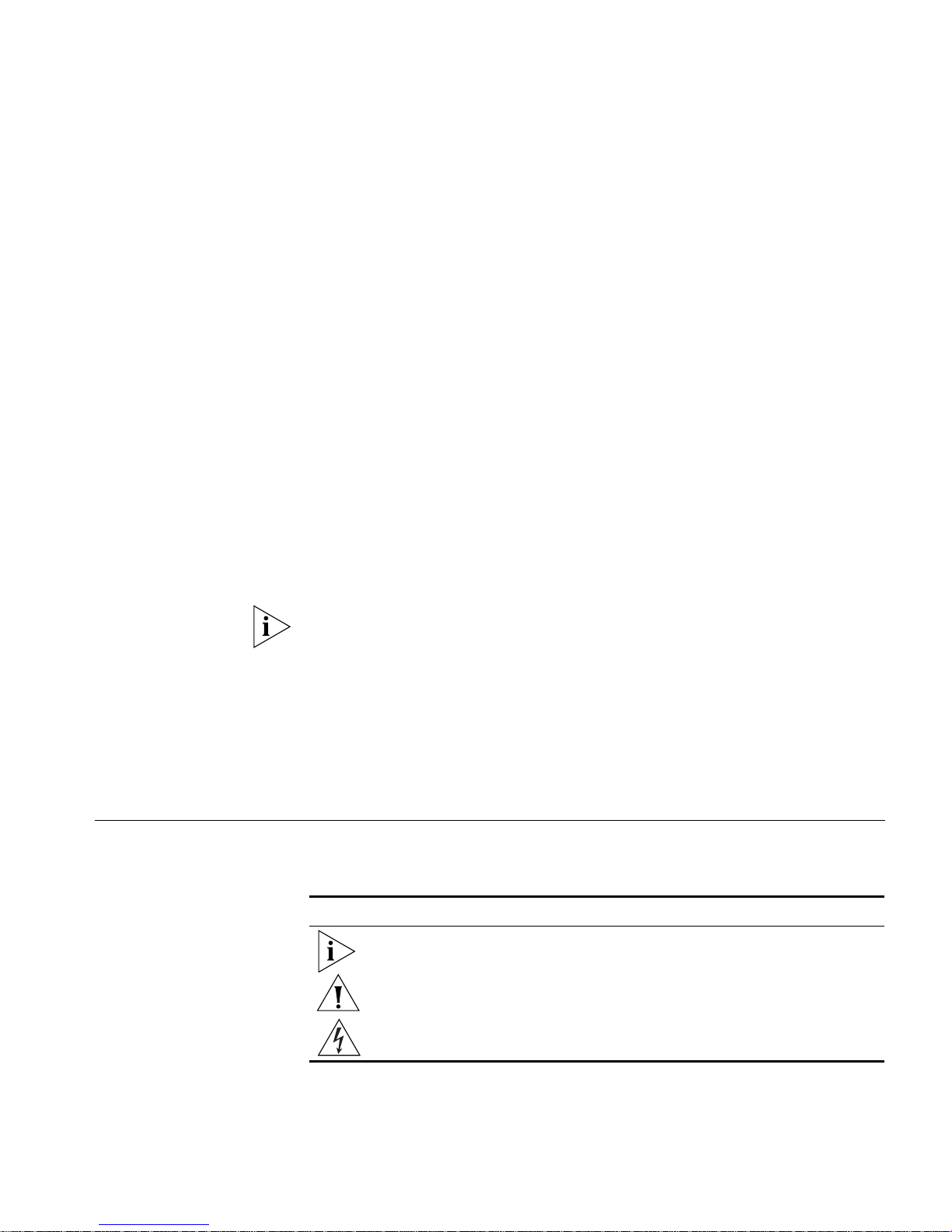
Back and Front Panels Figure 1 shows the back panel of the PathBuilder switch.
Figure 1 Back Panel
On/off
switch
Power
receptacle
RPS
connector
MODEL: xxxxxxx
PATHBUILDER
xxxxxx
100-240VAC, 50/60HZ, 1.0-0.5A
FOR CONTINUED PROTECTION
AGAINST FIRE HAZARD
REPLACE FUSE ONY WITH
SAME TYPE AND RATING
3COM CORP.
S/N:
NTWK
ADDR:
080002 04BA1E LAN
04BA1F
04BA20
04BA21
07/31/95
1SC05427
WAN-A
WAN-B
WAN-C
xxx
250V, F2A
SANTA CLARA, CA. MADE IN USA
Product
information label
8.3
20-0261-000
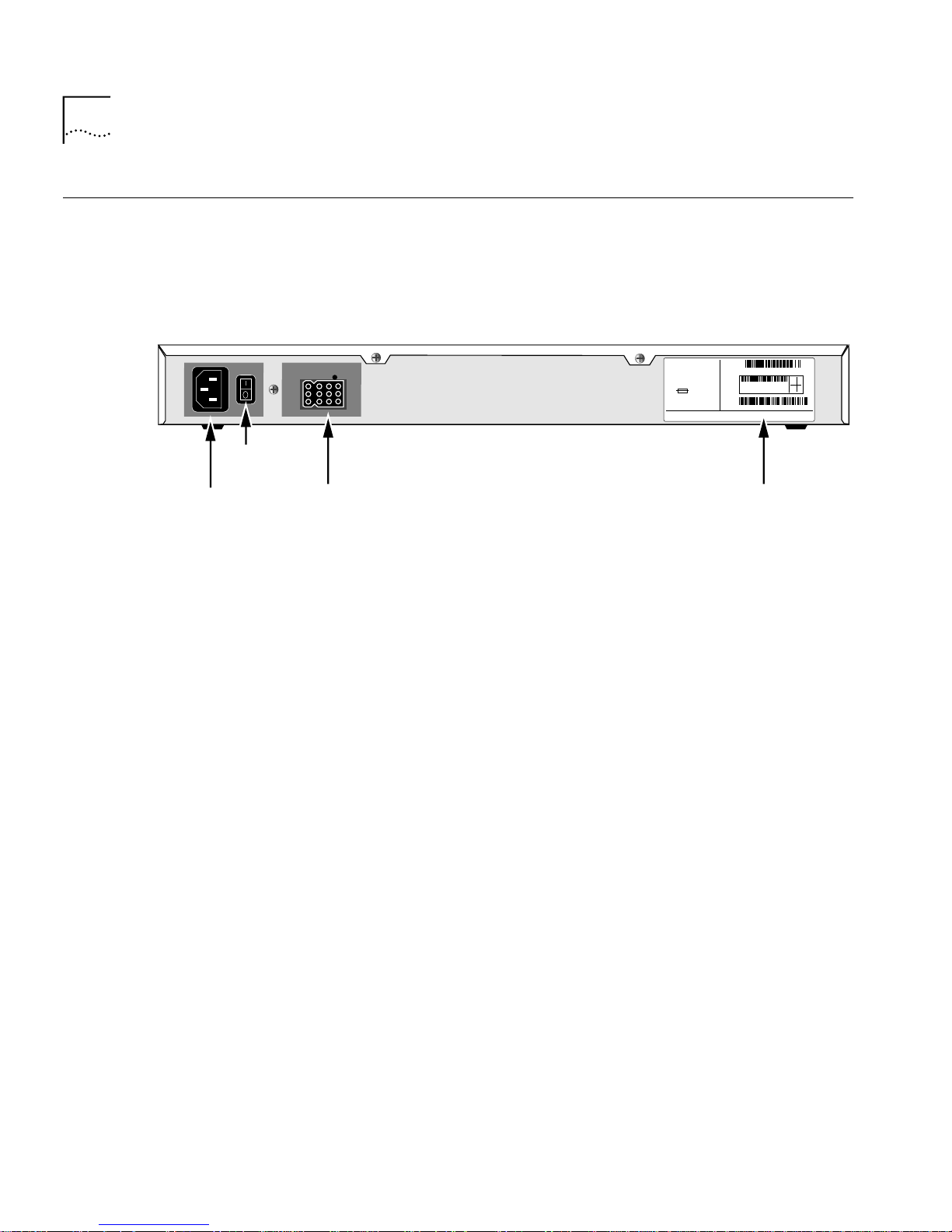
Figure 2 shows the front panel of the model S500 PathBuilder switch.
Figure 3 shows the front panel of the model S574 and model S578
PathBuilder switch.
Figure 4 shows the front panel of the model S580 PathBuilder switch.
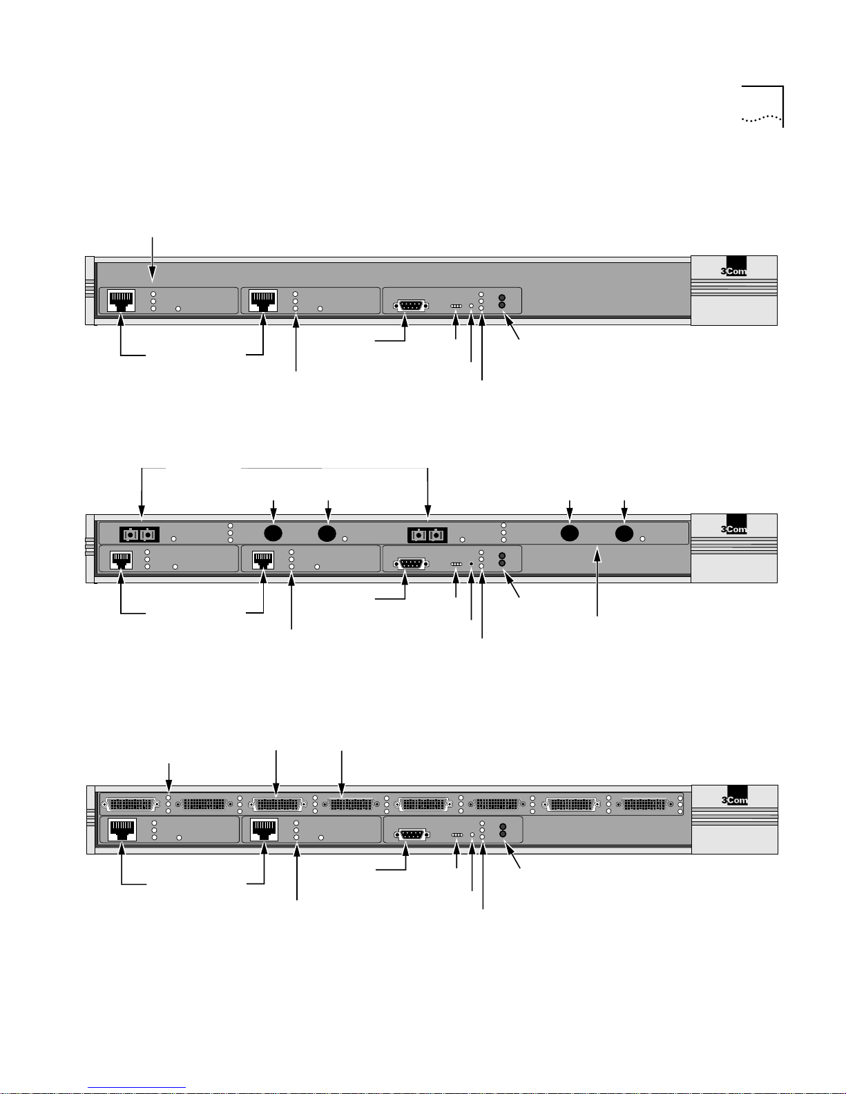
Figure 5 shows the front panel of the model S590 PathBuilder switch.
Figure 6 shows the front panel of the model S593/S595 PathBuilder
switch.
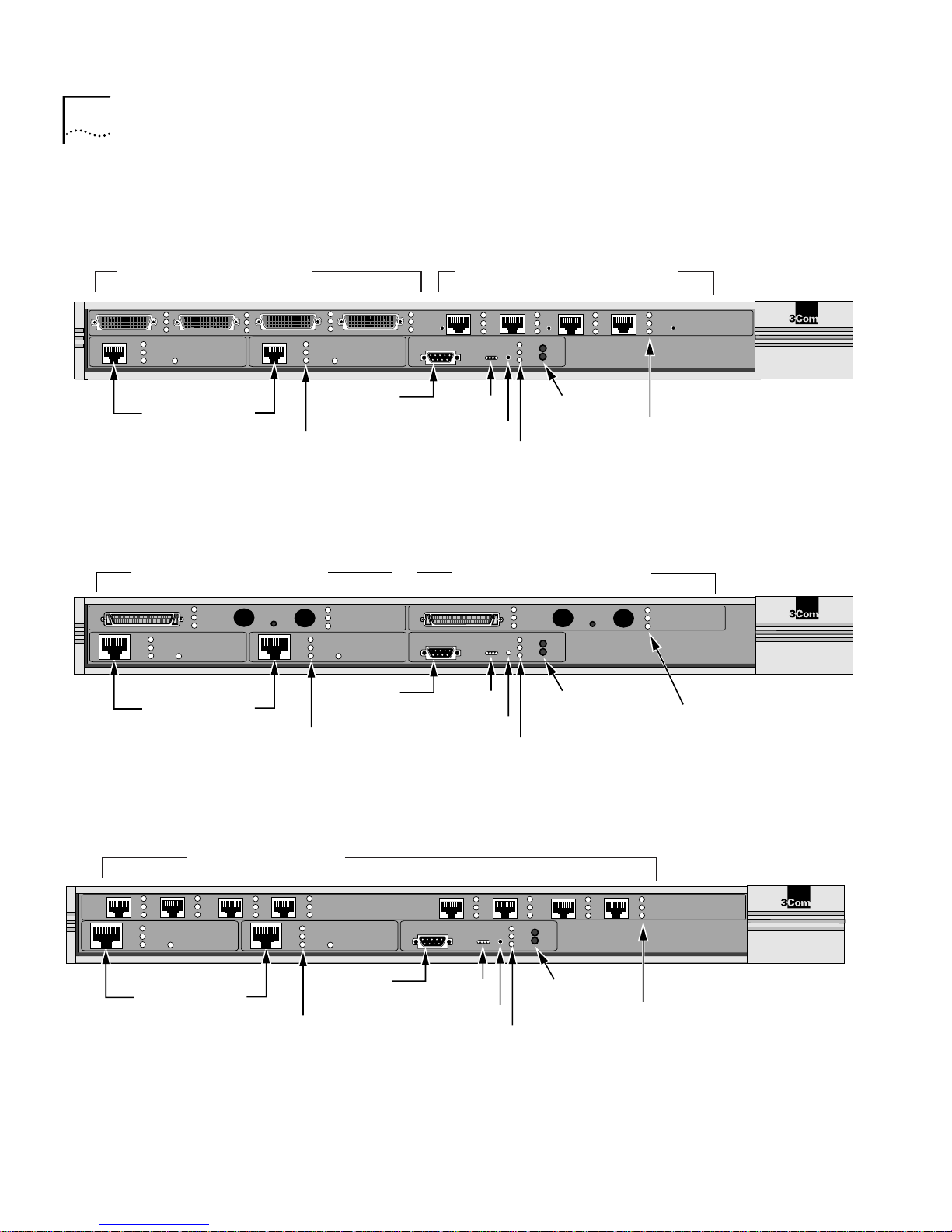
Figure 7 shows the front panel of the model S598 PathBuilder switch.
Figure 8 shows the front panel of the model S599 PathBuilder switch.
Page 21
Link, Active, and
Fault LEDs
Hardware Features 21
Figure 2 Front Panel (model S500)
®
Link
Active
Fault
100Mb
LAN 1
LAN 1 and LAN 2
Ethernet
connectors
connectors
OC3/3
Select
Link
Active
Fault
1
100Mb
LAN 1
LAN 1 and LAN 2
Ethernet
connectors
Status
LEDs
Reset
SYSTEM
Status
and Test LEDs
Link
Active
Fault
100Mb
LAN 2
Console
connector
Link, Active, Fault,
and 100Mb LEDs
Console
Figure 3 Front Panel (model S574 and S578)
ATM Coax
connectors
Link
Active
Fault
Rx
2
Link, Active, Fault,
and 100Mb LEDs
Coax 3
Link
Active
Fault
Tx
100Mb
Console
connector
Select
LAN 2
Console
OC3/4
Status
LEDs
Reset
Select
SYSTEM
Reset
Status
and Test LEDs
Run
Fwd
Load
Power
/Fault
Test
Fwd and
Fault LED
Run, Load,
Link
Active
Fault
Run
Fwd
Load
Power
/Fault
Test
Fwd and
Fault LED
Run, Load,
Power/
Power/
ATM Coax
connectors
Coax 4
Rx
Tx
PathBuilder S500 Series
Carrier, Alarm,
and Lpbk LEDs
Select
PathBuilder
S500 Series
ATM
®
Figure 4 Front Panel (model S580)
Link, Active, and
Fault LEDs
1
Link
Active
Fault
100Mb
LAN 1
LAN 1 and LAN 2
Ethernet
connectors
Flex-WAN serial connectors
Link, Active, Fault,
and 100Mb LEDs
Active
Fault
32
Link
LAN 2
100Mb
Console
connector
Console
56
SYSTEM
Run
Fwd
Load
Status
Status
Test
Power
/Fault
Fwd and
LEDs
Reset
Fault LED
Run, Load,
and Test LEDs
Power/
874
PathBuilder
S500 Series
®
Page 22
22 CHAPTER 1: OVERVIEW OF THE PATHBUILDER SWITCH
Figure 5 Front Panel (model S590)
Flex-WAN serial connectors
3A
Link
Active
Fault
1
100Mb
3B 3C
LAN 1
Put the new front panel drawing S590 here.
LAN 1 and LAN 2
Ethernet
connectors
Link, Active, Fault,
and 100Mb LEDs
Figure 6 Front Panel (model S593/S595)
use HSSI or BNC connectors
Link
Active
Fault
LAN 1 and LAN 2
WAN 1
Link
Active
Fault
LAN 1
100Mb
Ethernet
connectors
Link
Active
Fault
2
100Mb
LAN 2
Console
connector
Link
Active
WAN 1
Fault
Link
Active
Fault
100Mb
LAN 2
Console
connector
Link, Active, Fault,
and 100Mb LEDs
Ultra-WAN CSU/DSU connectors
Link
Active
3D
Fault
Console
4A
SYSTEM
Status
LEDs
Reset
Status
4B
Run
Reset
Load
Test
Fwd
Power
/Fault
4C
Fwd and
Power/
Fault LED
Carrier
Alarm
4D
Lpbk
PathBuilder S500 Series
Carrier, Alarm,
and Lpbk LEDs
®
Serial/WAN
Run, Load,
and Test LEDs
WAN 2
use HSSI or BNC connectors
Console
Status
LEDs
Reset
SYSTEM
Status
Link
Active
Fault
Run
Load
Test
Fwd
Power
/Fault
Fwd and
Power/
Fault LED
Link
Active
WAN 2
Fault
Link, Active, and
Fault LEDs
PathBuilder
S500 Series
®
Run, Load,
and Test LEDs
Figure 7 Front Panel (model S598)
Ultra-WAN connectors
Carrier
Alarm
3D
Lpbk
Link
Active
Fault
Link, Active, Fault,
and 100Mb LEDs
Link
Active
Fault
100Mb
3B
3C
LAN 1
3A
LAN 1 and LAN 2
Ethernet
connectors
LAN 2
100Mb
Console
connector
Console
4A
Status
LEDs
Reset
Status
4B
Run
Reset
Load
Test
SYSTEM
Run, Load,
and Test LEDs
Fwd
Power
/Fault
Fwd and
Power/
Fault LED
Carrier
Alarm
4C
4D
Lpbk
WAN
PathBuilder S500 Series
®
Carrier, Alarm,
and Lpbk LEDs
Page 23
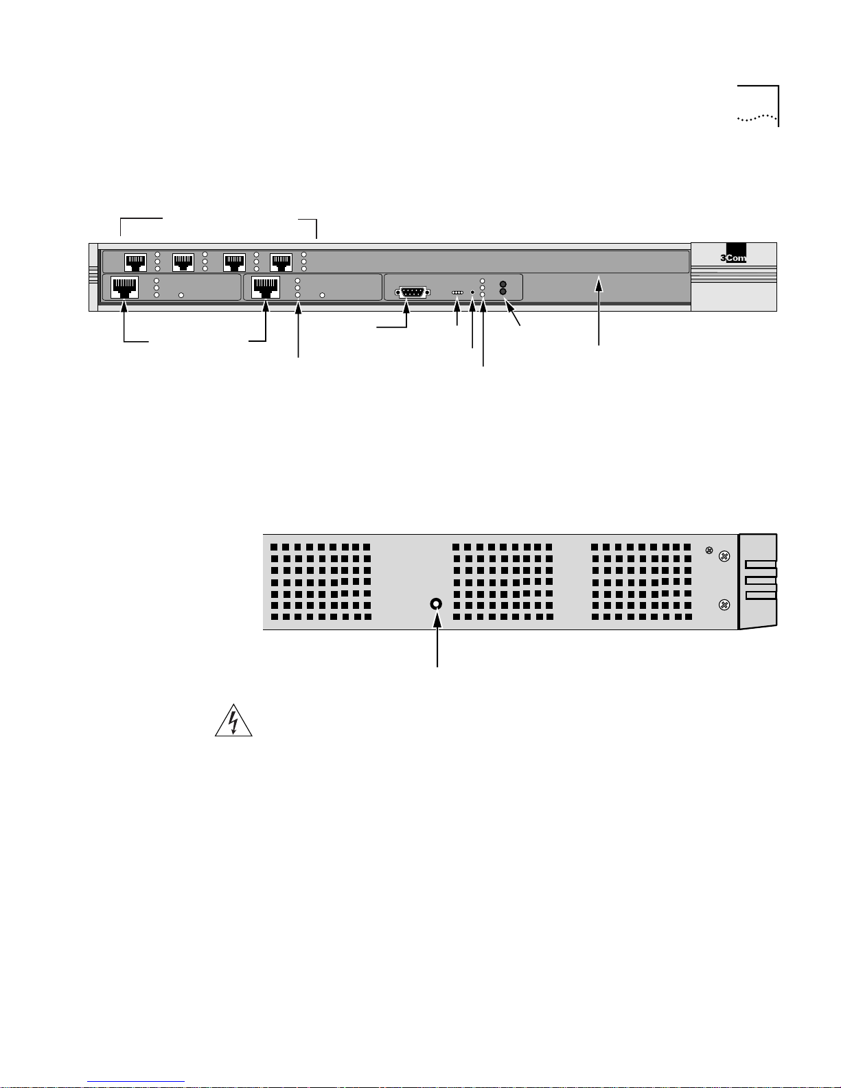
Figure 8 Front Panel (model S599)
Ultra-WAN connectors
Hardware Features 23
Link
Active
Fault
100Mb
3B
LAN 1
3A
LAN 1 and LAN 2
Ethernet
connectors
Hardware Interrupt
Switch
Carrier
Alarm
3C
3D
Lpbk
Active
Fault
Link
100Mb
LAN 2
Console
connector
Link, Active, Fault,
and 100Mb LEDs
Console
Status
LEDs
Reset
SYSTEM
Run
Reset
Load
Status
Test
Run, Load,
and Test LEDs
Fwd
Power
/Fault
Fwd and
Power/
Fault LED
WAN
PathBuilder S500 Series
Carrier, Alarm,
and Lpbk LEDs
The hardware interrupt switch is located on the left side of the switch
(when facing the front panel). Press the switch with a nonconductive
object, such as a plastic stylus, to activate the monitor firmware utility.
Left side of unit
®
Hardware interrupt switch
WARNING: Use only a nonconductive object, such as a plastic stylus, to
press the hardware interrupt switch. Do not use the tip of a pencil.
Graphite particles from the pencil may cause you to receive an electric
shock and may damage components on the motherboard.
Reset Button Pressing the Reset button resets the switch. The reset button is on the
front panel.
Page 24

24 CHAPTER 1: OVERVIEW OF THE PATHBUILDER SWITCH
Page 25

2
INSTALLING THE HARDWARE
This chapter describes how to install your PathBuilder switch.
Required
Equipment
Table 6 lists the items you receive in the shipping carton and items you
need to provide.
Table 6 Equipment Received and Equipment Needed
Shipping carton contents ■ PathBuilder switch
■ Power cable
■ Rack-mount kit
■ Software CD-ROM
■ Documentation and documentation CD-ROM
What you need to provide ■ Interface module (available from 3Com —
optional)
■ 10BASE-T or 100BASE-TX network cables
■ Flex-WAN cables (available from 3Com). See
“Flex-WAN Serial Connectors and Serial Cables”
on page 90 for more information about ordering
Flex-WAN cables.
■ ATM cables — optical fiber for OC3 connectors or
75-ohm coaxial cables for Coax (DS3/E3)
connectors
■ Terminal, PC, or modem and cable
*The software is preinstalled in the flash memory drive of the switch and automatically loads
when you turn on the power. The software CD-ROM is for software recovery purposes only.
*
WARNING: To eliminate cable noise emission in excess of FCC
regulations, part 15, subpart J, and EN55022B, all interconnection cables
should be equipped with shielded connectors, the backshells of which
must completely surround the cable shield.
For more information on cables, see Appendix C.
Page 26
26 CHAPTER 2: INSTALLING THE HARDWARE
Mounting the
Switch
Environmental
Requirements
You can mount your switch on a tabletop, stack several switches with
brackets, or mount the switch in a rack.
Table 7 provides the environmental requirements of the PathBuilder
switch.
Table 7 Environmental Requirements
Parameter Minimum Requirement Maximum Requirement
Temperature
Operating 5 °C 40 °C
Nonoperating -40 °C 75 °C
Altitude
Operating 15,000 ft
Nonoperating 40,000 ft
Relative Humidity
Operating 10% noncondensing 90% noncondensing
Nonoperating 10% noncondensing 90% noncondensing
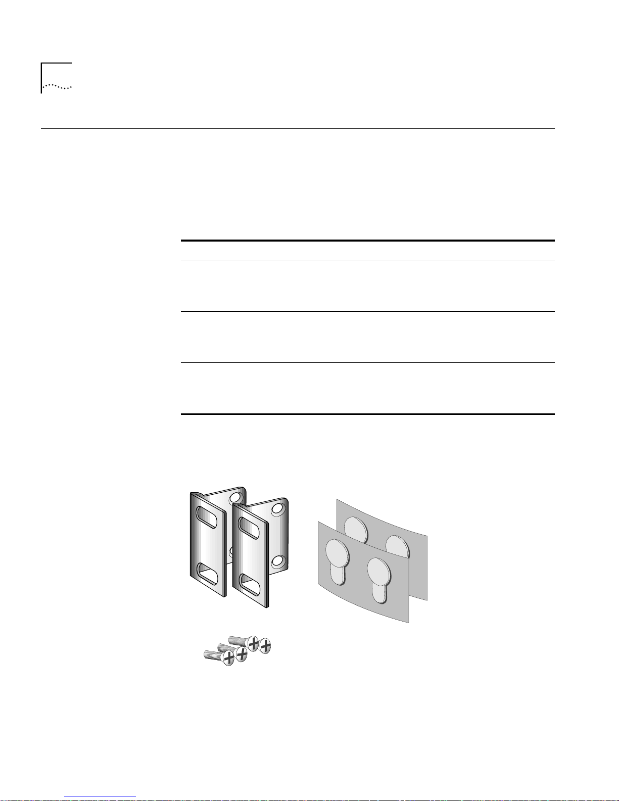
Mounting Kit The mounting kit contains the hardware shown in Figure 9.
Figure 9 Mounting Kit Contents
Two brackets
Four adhesive-backed
rubber feet
Four 8-32 Phillips
flathead screws for use
when stacking bridge/routers
Page 27
Mounting the Switch 27
Installing on a
Tabletop
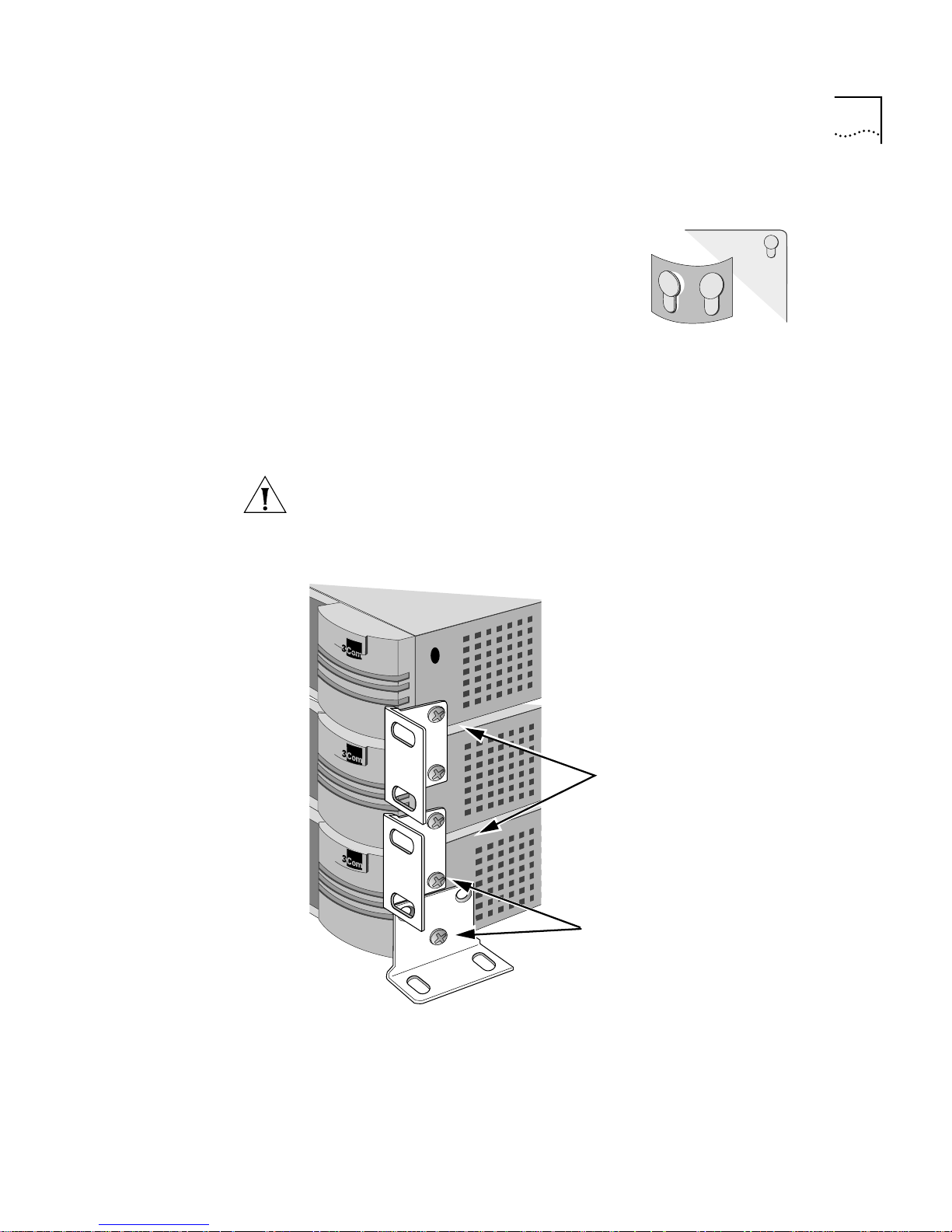
Stacking with
Brackets
If you plan to install your switch on a
tabletop, attach the rubber feet as
Attach feet to corners
of chassis bottom
shown.
Flex plastic sheet until
feet pop loose
See Figure 10 to securely stack several switches on a tabletop.
CAUTION: Do not restrict air flow around the sides and back of the
switch.
Figure 10 Stacking switches
Attach brackets as shown
to lock two units together
Place screws in holes as shown
Bottom bracket acts as a support
Page 28
28 CHAPTER 2: INSTALLING THE HARDWARE
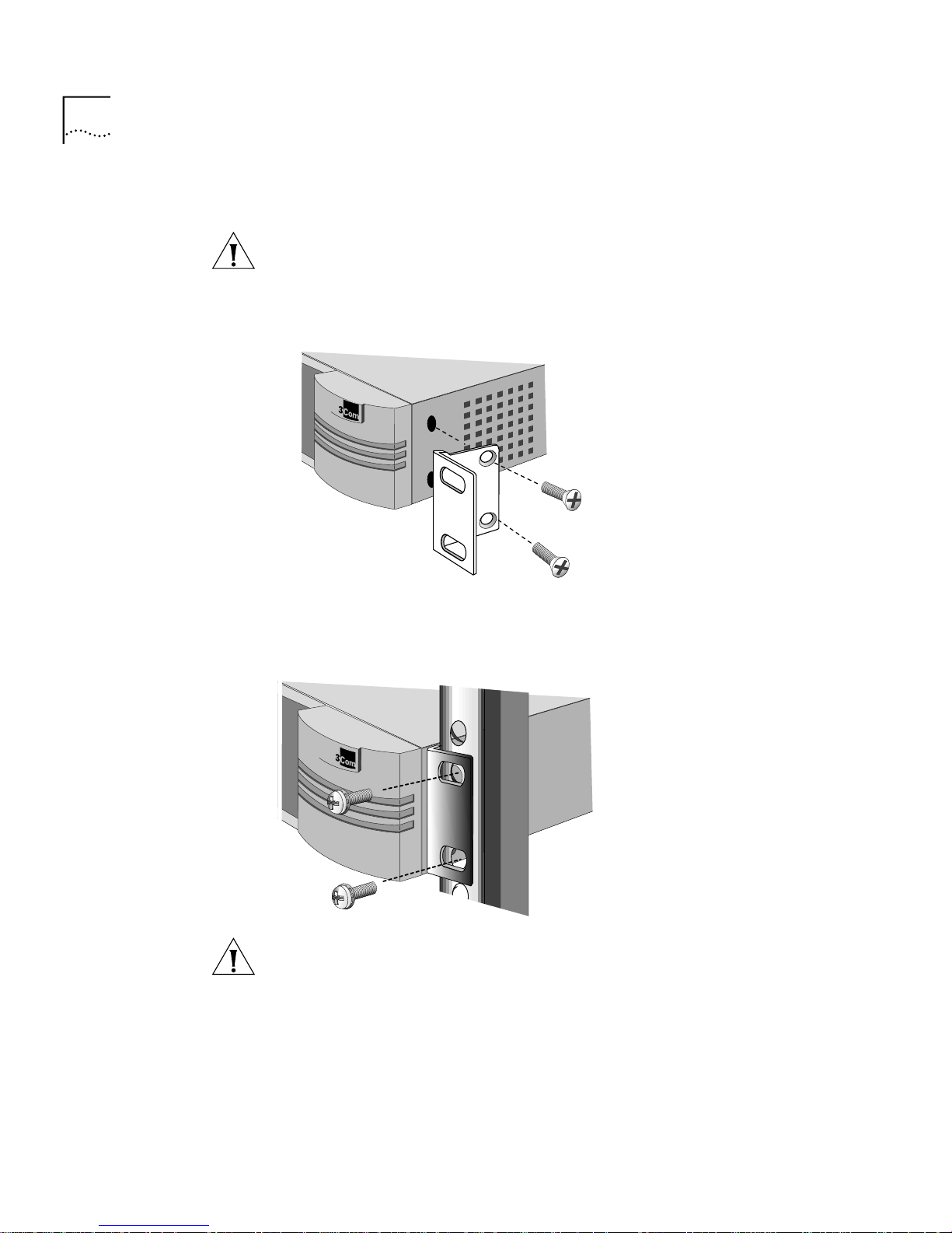
Installing in a Rack To install the switch in a rack, follow these steps:
CAUTION: Do not restrict air flow around the sides and back of the
switch.
1 Secure the rack-mount brackets to each side of the chassis using two
flathead screws per bracket.
2 Hold the chassis between the poles of the rack and attach the brackets to
the rack using panhead screws (you must provide these screws). Tighten
each screw securely.
CAUTION: Using fewer than two screws to secure the brackets to the
rack may cause the switch to fall and sustain damage not covered by the
warranty.
Page 29
Cabling the Connectors 29
Cabling the
Connectors
The PathBuilder switch has two Ethernet interfaces, and a number of
Flex-WAN serial interfaces, Ultra-WAN CSU/DSU, T3/E3 WAN, and/or
ATM interfaces, depending on the model. This section describes how to
cable each interface on your switch.
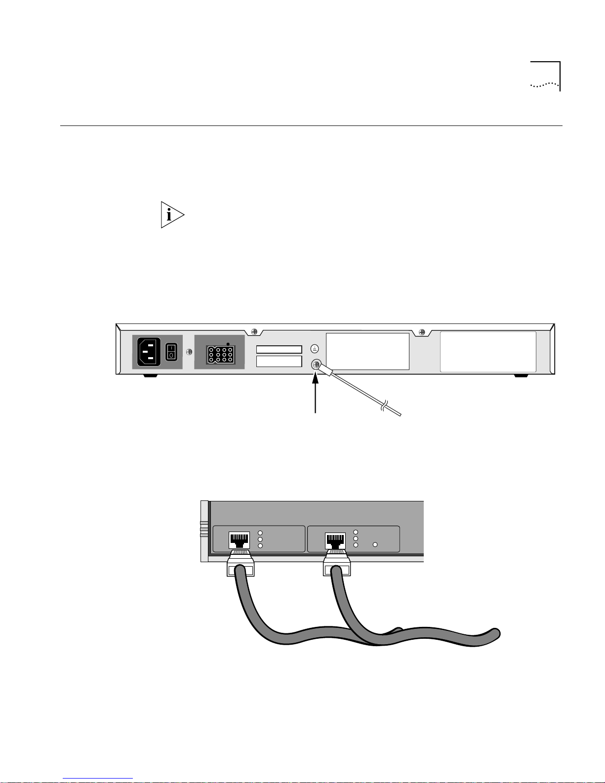
Some network topologies require that a grounding stud, separate from
the AC ground, be provided on the chassis of the networking equipment.
If this is required, ground the PathBuilder S574 ATM tunnel switch by
attaching a permanently connected protective earthing conductor using a
minimum 18 gauge wire with a UL-listed ring lug to a reliably connected
earth ground (see Figure 11).
Figure 11 Grounding the PathBuilder S574 ATM Tunnel Switch
Connect earthing conductor
using grounding screw
To earth ground
Cabling the LAN
Connectors
You can cable one or two Ethernet connectors using either 10BASE-T or
100BASE-TX cabling.
LAN 2
LAN 1
Link
Active
Fault
10BASE-T or 100BASE-TX cables
Link
Active
Fault
100Mb
For more information about Ethernet connectors and cables, see “LAN
Connector and Cables” on page 85.
Page 30
30 CHAPTER 2: INSTALLING THE HARDWARE
Cabling the Flex-WAN
Serial Connectors
Cabling the
Ultra-WAN CSU/DSU
Connectors
The model S580 and S590 PathBuilder switches have Flex-WAN serial
connectors. Order the appropriate Flex-WAN cable from 3Com for your
serial device. See “Flex-WAN Serial Connectors and Serial Cables” on
page 90 for more information about the Flex-WAN cables.
Link
Active
Fault
LAN 1
Link
Active
Fault
100Mb
Console
SYSTEM
Status
Run
Fwd
Load
Power
/Fault
Test
LAN 2
Flex-WAN cables
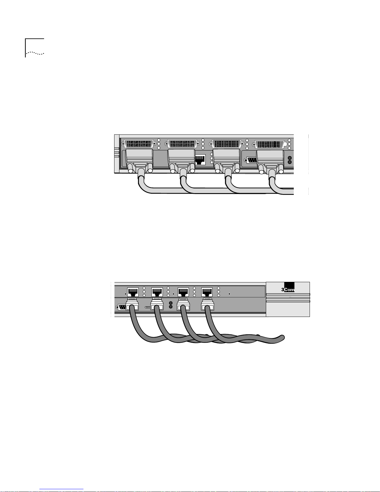
The models S590 and S598 PathBuilder switch have Ultra-WAN CSU/DSU
connectors. You can cable one or more of these connectors using RJ-48C
connectors. See “Ultra-WAN CSU/DSU Connector and RJ-48C Cables”
on page 103 for more information about the Ultra-WAN CSU/DSU
cables.
Console
Reset
4B
Run
Load
Test
4A
SYSTEM
Status
RJ-48C cables
Fwd
Power
/Fault
Carrier
Alarm
4C
4D
Lpbk
PathBuilder S500 Series
Serial/WAN
®
Page 31

Cabling the Connectors 31
Cabling the HSSI
T3/E3 Connectors
Cabling the Coax
T3/E3 (BNC)
Connectors
The model S593 PathBuilder switch has two T3/E3 connectors per
interface. You can connect using either high-speed serial interface (HSSI)
cables or BNC cables. See “High-speed Serial Interface (HSSI) Cables” on
page 105 for more information about the HSSI cables.
Link
Active
Fault
100Mb
Link
Active
Fault
LAN 1
HSSI cable
Link
Active
Fault
Link
Active
Fault
100Mb
WAN 1
LAN 2
You can cable one or two WAN connectors using either the HSSI cables
shown above or the coax T3/E3 (BNC) cables shown here.
Link
Active
Fault
Link
must be one somewhere in our archive.
Active
Fault
100Mb
LAN 1
Link
Active
Fault
Link
Active
Fault
100Mb
WAN 1
LAN 2
T3/E3 (BNC) cables
Console
Page 32

32 CHAPTER 2: INSTALLING THE HARDWARE
Cabling the ATM
Connectors
You can cable the ATM connections using either single-mode or
multi-mode optical fiber cables for the OC3 connectors or 75-ohm
coaxial cables for the Coax (DS3/E3) connectors.
Either the OC3 or Coax (DS3/E3) connectors can be used, but not at the
same time.
Cabling the ATM OC3 Connectors
You can cable one or two OC3 connectors using single-mode or
multi-mode OC3 optical fiber cables as shown here.
OC3/3
Link
Active
Fault
Select
100Mb
LAN 1
Active
Fault
Link
Coax 3
Rx
Tx
Link
Active
Fault
100Mb
Single-mode or multi-mode
OC3 optical fiber cables
Select
LAN 2
Console
WARNING: Optical Safety. Under normal viewing conditions there is no
hazard from the T ransmit LED. It is recommended however that the LED is
not viewed through any magnifying device while it is powered on. It is
advisable that the fiber TX port and fiber cable ends are never viewed
directly when powered on.
Page 33

Attaching a Redundant Power System 33
Cabling the ATM Coax (DS3/E3) Connectors
You can cable the ATM Coax (DS3/E3) connectors using two 75-ohm
coaxial (BNC) cables as shown here.
Attaching a
Redundant Power
System
Wall outlet
OC3/3
Link
Active
Fault
Select
100Mb
LAN 1
Link
Active
Fault
Coax 3
Rx
Tx
Select
Link
Active
Fault
100Mb
LAN 2
Console
75-ohm coaxial (BNC) cables
You can attach your PathBuilder switch to a PathBuilder Redundant
Power System (RPS).
PathBuilder switch
Power cable
Power cable
For full power supply redundancy, attach one end of the RPS cable to the
rear panel on the switch and the other end to the RPS. Then attach one
PathBuilder Redundant Power System
RPS cable
Page 34

34 CHAPTER 2: INSTALLING THE HARDWARE
end of the power cord to the rear panel on the switch and the other end
to a power outlet.
In this configuration, the internal supply provides power. If the internal
supply fails or is switched off, or if there is a power failure, the RPS is
activated and the switch reboots.
To reset a switch in this configuration, turn the power off, wait 5 seconds
and turn it back on. The switch switches to the RPS, then switches back
to the internal supply to reboot.
CAUTION: For system susceptibility protection, always leave the AC cord
attached to the switch and to a power outlet.
Internal power supply failure is rare. If it occurs, the power switch on your
switch will not operate. To reboot, unplug the RPS cable and then plug it
back in. Replace your switch with another switch that has a functioning
internal power supply as soon as possible. Contact your 3Com
representative to replace your switch.
Connecting a PC,
Terminal, or
Modem
Connect a PC running a terminal emulation program, a terminal, or a
modem to the console port on the PathBuilder switch to configure the
switch software and review startup and system operation messages.
To connect a PC, terminal, or modem to the switch, follow these steps:
1 Obtain a cable to connect the device to the console port on the switch.
See “Console Connector and Cables” on page 83 for cable pinouts.
The console port is a 9-pin male connector.
For the PC, use a 9-pin female to 9-pin female null modem-type cable.
For the terminal, use a 9-pin female to 25-pin null modem-type cable.
For the modem, use a 9-pin female to 25-pin male straight-through-type
cable.
2 Connect one end of the cable to the console port on the PathBuilder
switch and the other end to the serial port on the back of your device.
Page 35

Shutting Down 35
3 Verify that configurable parameters of your device match the
configuration settings of the console port specified in Table 8.
Table 8 Console Port Configuration Settings
Characteristic Setting
Baud rate 9600
Databits 8
Parity None
Stop bits 1
DTR Ignored
Duplex Full
Echo Off
Flow control X-on/X-off
4 Turn on the device.
Shutting Down If your PathBuilder switch is not connected to an RPS, turn off the power
by pressing the off (0) side of the power switch on the back panel. If your
system is connected to an RPS, turn off the power by unplugging the RPS
cable from the system and then pressing the off (0) side of the power
switch.
Page 36

36 CHAPTER 2: INSTALLING THE HARDWARE
Page 37

LOGGING ON AND PERFORMING
3
A
DMINISTRATIVE TASKS
This chapter describes the following:
■ Starting up the system
■ Logging on
■ User interfaces
■ Performing basic administrative tasks
Table 9 summarizes the administrative tasks described in this chapter and
indicates whether performing each task is required, recommended, or
optional.
Table 9 Administrative Task Summary
Task Status of Task
Changing the Root Password Required
Changing the Default Console Port Baud
Rate
Adding User Accounts Optional
Setting the Time and Date Recommended
Setting System Information Required
Setting Up Security Access Recommended
Setting up SNMP Management Recommended
Do only if you want to attach a terminal
with a baud rate other than 9600.
For more information on each of the commands and parameters used in
this chapter, see Reference for Enterprise OS Software.
Starting the System To start up your PathBuilder switch, plug one end of the power cord into
the rear panel of the switch and the other end into your power outlet.
Press the toggle switch to the On position.
Page 38

38 CHAPTER 3: LOGGING ON AND PERFORMING ADMINISTRATIVE TASKS
Verifying Successful
Startup
The startup process takes a few seconds. When the startup process has
successfully completed, the LEDs on the front panel should be on or off
as described in Table 10.
For serial LEDs to display properly, a serial device must be cabled to the
PathBuilder switch and powered on.
If the LEDs on your switch appear different from those shown in Table 10,
the switch may have a problem. See Appendix E for more information.
Table 10 LED Status at Successful Startup
LED Status
LAN
Link On
Active On or blinking
Fault Off
Flex-WAN SERIAL
Link On
Active On
Fault Off
Ultra-WAN CSU/DSU *
Carrier Off
Alarm Off
Lpbk Off
T3/E3
Link On
Active On
Fault Off
ATM OC3/Coax (DS3/E3)
LInk On
Active On
Fault Off
SYSTEM
Status All off
Fwd Off or blinking
Power/Fault Green
Run On
Page 39

Logging On to the System 39
Table 10 LED Status at Successful Startup
LED Status
Load Off
Test Off
* During normal startup sequencing, the CSU/DSU LEDs periodically flash on and off. When the
startup sequencing is complete, these LEDs remain off. When you have completed configuring
the CSU/DSU interfaces and the interfaces are operational, these LEDs remain on.
Logging On to
the System
When your switch starts up, it takes a few seconds to complete the
initialization process. While the switch is initializing, various messages will
appear on your terminal. The switch has finished booting when the
following message is displayed:
System Initialized and Running
To log on, follow these steps:
1 Press any key on the keyboard.
The following prompt is displayed:
NetLogin:
2 Enter:
root
Root is the default account name. The following prompt is displayed:
Password:
3 Press the Return key.
Pressing the Return key enters a null string, which is the default local
password. The Network Manager prompt is displayed:
Enterprise OS #
Configuring an IP
Address
Before you can access the PathBuilder switch over one of the 10/100
Ethernet interfaces, you must assign an IP address and an IP route entry.
1 To assign an IP address, use:
SETDefault -IP !<portnumber> NETaddr = <IPaddress> <subnet mask>
For example, to set the IP address to 555.666.777.888 and the subnet
mask to 255.255.253.0 on LAN port 1, enter:
SETDefault -IP !1 NETaddr = 555.666.777.888 255.255.252.0
Page 40

40 CHAPTER 3: LOGGING ON AND PERFORMING ADMINISTRATIVE TASKS
2 To assign an IP route to a gateway, use:
Add -IP ROUte <gateway IP address> <!metric>
■ For example, to set an IP route to gateway 111.222.333.444, enter:
SETDefault -IP ROUte 111.222.333.444 1
Choosing the User
Interface
This section describes how to access the menu-driven and command-line
user interfaces. Detailed information for both types of interfaces is
provided so that you can choose the one that best suits your needs.
After you have configured the IP address of the PathBuilder switch, you
can access the user interface using one of the following methods:
■ Telnet to the switch from a device (for example, a workstation) on the
same extended network or internetwork.
■ Use the embedded HTTP server, Web Link, which provides
performance and health monitoring graphs, task-based configuration,
and diagnostics.
■ Use Transcend Network Control Services, which provides extensive
management capabilities for use from a network management
station.
■ Use Simple Network Management Protocol (SNMP) to view and
configure a subset of the parameters from a remote host. For
information on preparing the switch to run SNMP, see Using
Enterprise OS Software.
Deciding Which
Interface to Use
After you have accessed the user interface, you need to decide whether
to use the menu-driven or the command-line interface.
■ If you are unsure of the command syntax, use the menu-driven
interface.
For more information about the MEnu command, see Reference for
Enterprise OS Software. For information on how to use the
menu-driven interface, see the next section.
■ If you know the exact syntax, enter the command at the system
prompt.
The syntax for each command and parameter is described in
Reference for Enterprise OS Software.
Page 41

■ If you are using Netscape 4.5 or Internet Explorer 4.0 or later versions
of these web browsers, you can use Web Link, a web-based
configuration and monitoring tool, to configure and manage your
switch. For more information on how to use Web Link, see Using
Enterprise OS Software.
Using Menus The MEnu command allows you to:
■ Display a list of available services.
■ Choose a service and display the list of parameters available for
that service.
■ Display a list of parameters in the current service.
■ Choose a parameter and display the commands used with it.
■ Check the active and default values of a parameter.
■ Display the online help syntax of a parameter.
■ Enter the new value of a parameter.
Choosing the User Interface 41
The following prerequisites and notes apply when you use the
menu-driven interface:
■ You must have Network Manager privilege.
■ You cannot access some parameters; for example, you cannot alter
the number of lines on the screen, or change privilege level.
To use the menu-driven interface, follow these steps:
1 Log on as root or as a user with Network Manager privilege.
2 If you have not selected a particular service, enter:
MEnu
The Main menu is displayed.
3 Select the desired service.
For example, selecting 1 from the Main menu displays a menu for the SYS
Service.
4 Select the parameter you want to configure.
For example, if you selected 27 from the SYS Service menu, information
for that parameter is displayed.
The first part of the screen displays the value of the parameter. The
second part lists the commands from which you can choose.
Page 42

42 CHAPTER 3: LOGGING ON AND PERFORMING ADMINISTRATIVE TASKS
5 To escape out of a menu, press the Return key, which takes you to the
previous menu level.
For example, if you are at the Main menu and you press the Return key,
you will return to the command-line interface.
Using the
Command-line
Interface
To use the command-line interface, follow these steps:
1 Log on as root or as a user with Network Manager privilege.
2 Type the command name. For a complete list of commands, enter a
question mark (?).
If your command does not require a service name, parameter, or values,
skip to step 3. If your command requires more modification, continue to
step a.
a If the command has additional options, such as a port or path number,
include it after the command name.
When you include a specific port or path number in the command,
that command focuses on that particular port or path. If the port or
path number is not included, the command provides information on
all ports or paths.
For more information on ports, paths, or commands, see Reference
for Enterprise OS Software.
b If the command is modified by a parameter, type the service name (if
necessary), the parameter name, and values.
The service part of the command focuses the action of the command
on a particular service of the system.
In some cases, you may not need to enter the service name. For
example, if a parameter is unique to a particular service, the service
need not be specified as part of the command.
The parameter is the object of the action of the command. If two or
more services have parameters of the same name, you must include
the service name in the syntax so the command can be executed
successfully.
The value part of the command specifies how you want the parameter
to be set. Values include numerics, strings, or addr esses depending on
the parameter.
3 Press the Return key after typing the complete command.
Page 43

Changing the Root Password 43
The software includes online help for commands, services, parameters,
and syntax. The syntax style that appears in the online help is the full
form syntax; it contains full names and visual cues for entering
commands. You can also enter commands using an abbreviated version
of the syntax style.
Using Web Link When you use Web Link, PathBuilder switch configuration tools are
dynamically generated HTML pages that are based on an internal menu
system. Using Web Link you can perform protocol service configuration
following standardized step-by-step procedures or on an individual
service per parameter basis. Help for all service configuration is presented
on-line. Web Link also provides Java graphs for high-level health and
low-level protocol and interface statistics. Diagnostics are also available.
See the Using Web Link Network Management Tools chapter in Using
Enterprise OS Software for instructions on how to set up IP routing and
access Web Link.
Using Transcend The Transcend Network Control Services application provides excellent
Changing the Root
Password
tools for managing groups of tunnel switches. See the Transcend
documentation for further information.
The default root password is a null string, which is generated by pressing
the Return key.
You should specify a new password immediately after you log on for the
first time. Changing the root password prevents unauthorized users fr om
accessing and executing software commands and parameters.
The root user has two privilege levels and passwords: Network Manager
and User. The User privilege enables only a subset of software
commands. You should assign passwords for both levels. If you log in as
root and enter the Network Manager password, you have Network
Manager privilege. If you log in as root with the User password, you have
User privilege.
You might log on with the User password if you only want to examine
parameters and statistics. If you want to change the privilege level
without logging off, use:
SET -SYS PRIvilege = User | NetMgr
Page 44

44 CHAPTER 3: LOGGING ON AND PERFORMING ADMINISTRATIVE TASKS
The following guidelines exist when changing a password:
■ You must be logged on as root with Network Manager privilege.
■ You must define the Network Manager password before you define
the User password.
■ You must clear the User password before you clear the Network
Manager password.
To change the password for both privilege levels, enter:
SysPassWord
A menu is displayed.
Follow the menu to set the Network Manager password and then the
User password.
CAUTION: You should set both the Network Manager and the User
password. If the User password is not set, any unauthorized user can
logon with User level privilege.
Changing the
Default Console
Port Baud Rate
To attach a terminal with a baud rate other than 9600, follow
these steps:
1 At the Network Manager prompt (Enterprise OS #), enter:
SysconF
The System Configuration menu is displayed.
2 Select the Console Port option.
A submenu displays the console port baud rate options.
3 Select the baud rate you want to use.
4 Set the terminal baud rate to match the baud rate configured for the
console port.
CAUTION: Do not reset the switch before changing the terminal baud
rate. After the switch resets, the new baud rate is used and you will not
be able to access the system software to enter any commands at the
default 9600 baud rate.
5 After you change the terminal baud rate, reset the switch.
The new console port baud rate does not become effective until you have
reset the switch.
Page 45

Adding User Accounts 45
Adding User
Accounts
You can add user accounts when logged in as “root” with Network
Manager privileges.
To add a user account, log on as root and use:
AddUser [<username>]
If you do not specify a username, you will be prompted for one. Specify
the privilege and password at the prompts.
Delete an account using:
DELeteUser [<username>]
To force a user password to expire, use:
EXPire [<username>]
To manage multiple users and see all user accounts, enter:
UserManage
Any user can change their password by entering:
PassWord
Setting the Time
and Date
3Com recommends setting the time and date. Use:
SET -SYS DATE = <YYYY/MM/DD HH:MM[:ss]>
Enter the time in 24-hour-clock format. For example, to set the date and
time to January 10, 1996, 2:40 p.m., enter:
SET -SYS DATE = 1996/1/10 14:40
You can use the Network Time Protocol (NTP) service to synchronize the
computer clock in a distributed network.
Page 46

46 CHAPTER 3: LOGGING ON AND PERFORMING ADMINISTRATIVE TASKS
Setting System
Information
You should set the system name to identify this unit to SNMP
management stations. You can also set the location and contact so that
other system administrators can contact you for information.
Use the Web Link system configuration screens to set these values from a
browser.
To set the system name, location, and contact, follow these steps:
1 (Required) Assign a name to the switch using:
SETDefault -SYS SysNAMe = Ò<string>Ó
For example, to set the system name to Engineering.SanJose, enter:
SETDefault -SYS SysNAMe = ÒEngineering.SanJoseÓ
2 (Optional) Specify the system location using:
SETDefault -SYS SysLOCation = Ò<string>Ó
For example, to set the system location to SecondFloor.Lab, enter:
SETDefault -SYS SysLOCation = ÒSecondFloor.LabÓ
3 (Optional) Identify the contact person managing the switch using:
Setting Up Security
Access
SETDefault -SYS SysCONtact = Ò<string>Ó
For example, to identify John Smith as the system contact and
(408)555-1111 as the phone number at which to reach him, enter:
SETDefault -SYS SysCONtact = ÒJohn Smith (408) 555-1111Ó
If the system contact is specified, users can obtain this information using
the SHow -SYS SysCONtact command.
To allow system administrator-only read/write access to files, use these
commands and parameters:
■ The SNMP Service parameter COMmunity modifies the list of
communities and managers with read/write access to the device. By
default, any application can read the SNMP MIBs. To provide write
access for Transcend upgrade and configuration management, a
community and manager(s) must be configured. For information on
how to use the COMmunity parameter, see Reference for Enterprise
OS Software.
Page 47

Setting Up Security Access 47
■ The SysLog feature generates a log message on a network
management workstation that captures configuration changes and
events for monitoring switches. For more information on this feature,
see Using Enterprise OS Software.
■ The -SYStem service parameters TelnetMgr and WebLinkMgr let you
set up a list of allowed Telnet and Web Link managers. Both the Telnet
and Web Link shared this list of allowed managers. Adding or
changing a member of this list using one of the TelnetMgr parameter
to change the list of allowed managers for telnet changes the list of
allowed managers for Web Link as well.
Page 48

48 CHAPTER 3: LOGGING ON AND PERFORMING ADMINISTRATIVE TASKS
Page 49

BASIC CONFIGURATION OF PORTS,
4
Paths, Ports, and
Connectors
P
ATHS, AND CONNECTORS
This chapter contains conceptual information about ports, paths, and
connectors and contains basic configuation procedures for each of the
interfaces on your PathBuilder switch.
The models S590, S598 and S599 PathBuilder switches have Ultra-WAN
connectors, which need to be configured (in addition to port and path
configuration) before they are shown in the port and path configuration
displays.
Ports and paths are the fundamental interface syntax on the switch. This
section defines ports, paths, and connectors and explains how they are
numbered.
The fundamental difference between paths and ports is that the path is
the physical interface and the port is the logical interface in the software
that is mapped to the physical path.
■ A connector is the physical interface itself.
■ A path is a connection on the physical interface that connects a switch
■ A port is the logical interface used by the protocol software to
■ All connectors, by default, carry one path each. This default can be
By default, each path is assigned to one port. For example, all network
traffic received on physical path 1 is treated by the softwar e as arriving on
logical port 1, and all traffic that the software transmits through logical
port 1 passes through physical path 1.
to a physical network medium such as Ethernet, a T1/E1 line, or a
serial line. Each path is associated with a connector.
represent a connection to a network.
changed on Ultra-WAN connectors such that an Ultra-W AN connector
carries multiple paths, as is required in ISDN PRI operation.
Page 50

50 CHAPTER 4: BASIC CONFIGURATION OF PORTS, PATHS, AND CONNECTORS
A path that is assigned at system initialization time to a port is a static
path. A path that is assigned to a port when a dial call is placed is a
dynamic path.
Multiple Port and
Path Bindings
Multiple paths can be assigned to a port and multiple ports can be
assigned to a path as described in Table 11.
Table 11 Port and Path Options
Option Description
Multiple paths per
port: dynamic paths
Multiple paths per
port: static paths
Multiple ports per
path: virtual ports
A dynamic path is not assigned to any one port, but is
available in a dial pool. A dial pool enables you to dial
multiple destinations, use bandwidth-on-demand, and
failover to another line without having to reserve specific
paths for a port. A port may require multiple paths from the
dial pool.
Use multiple static paths on the same port:
■ To use a path for disaster recovery, dial-on-demand,
failover, or bandwidth-on-demand.
A virtual port can be assigned to a path or to a SysCallerID
that represents a remote site.
Dynamic Paths Ports running MLP can use a dial pool of available paths. A dial pool
enables you to dial multiple destinations, use bandwidth-on-demand,
and failover to another line without having to reserve specific paths for a
port. A dial pool is created when you unbind a path from its port by
using:
SETDefault !<path> -PATH DialCONTrol = DYNamic
Virtual Ports To configure multiple ports over one path, you create virtual ports. A
virtual port can be assigned to a static path, or for PPP as using in a virtual
private network (VPN), it can be assigned to the SysCallerID of a remote
site. SysCallerID virtual ports use paths in a dial pool and are not
associated to any one path.
A virtual port functions the same way as a nonvirtual port does, that is, as
a logical interface that represents a connection to a network.
Page 51

51
Port/Path Services
and Syntax
Path and port parameters have their own dedicated service type
indicators, that are used in commands that change the setting of these
parameters.
Path parameters use the Path Service and port parameters use the Port
Service.
Table 12 lists the path and port numbering syntax rules that are used for
default naming for PathBuilder S5xx series switches.
Table 12 PathBuilder Path/Port Syntax Rules
Path/Port
Interface
LAN connectors <n> n = 1 or 2
FlexWAN Serial
connectors
Ultra-WAN CSU/DSU
connectors*
T3/E3 connectors <n> n = 3 or 4
ATM connectors <n> n = 3 or 4
Syntax
<nm> n = 3 or 4
<nm.p> n = 3 or 4
Syntax Description
m = a, b, c, or d
m = a, b, c, or d
p = 1, 2, ...30
Connector Services
and Syntax for
Ultra-WAN Interfaces
* The Ultra-WAN CSU/DSU interfaces on the model S590/S598/S599 PathBuilder switches
support multi-path ISDN PRI dial, as well as single-path leased unstructured operation.
Connector parameters do not have a dedicated service type indicator;
they use the Path Service type indicator. Table 13 lists the Ultra-WAN
connector syntax rules for the model S590/S598/S599 PathBuilder switch.
Table 13 PathBuilder S590 Connector Syntax Rules
Connector
Interface
Ultra-WAN CSU/DSU
Connectors
Syntax
<4m> and
<3m>
Syntax Description
m=a, b, c, or d
Page 52

52 CHAPTER 4: BASIC CONFIGURATION OF PORTS, PATHS, AND CONNECTORS
Path and Port
Numbering
Model S500 Figure 12 shows the path/connector to port number mappings for the
Link
Active
Fault
100Mb
LAN 1 maps
path 1 to port 1
Model S580 Figure 13 shows the path/connector to port number mappings for the
LAN 1
This section provides the default port and path number mapping for the
PathBuilder switch.
model S500 PathBuilder switch.
Figure 12 Model S500 PathBuilder Switch Path to Port Mappings
®
Link
Active
Fault
100Mb
LAN 2 maps
path 2 to port 2
LAN 2
Console
SYSTEM
Status
Run
Fwd
Load
Power
/Fault
Test
PathBuilder
S500 Series
model S580 PathBuilder switch.
Figure 13 Model S580 PathBuilder Switch Path to Port Mappings
Maps
path 3a
to port 3a
LAN 1 maps
path 1 to port 1
path 3b
to port 3b
Link
Active
Fault
100Mb
Maps
LAN 1
Maps
path 3c
to port 3c
Link
Active
Fault
LAN 2 maps
path 2 to port 2
Maps
path 3d
to port 3d
LAN 2
100Mb
Maps
path 4a
to port 4a
Console
SYSTEM
Status
Maps
path 4b
to port 4b
Run
Fwd
Load
Power
/Fault
Test
Maps
path 4c
to port 4c
Maps
path 4d
to port 4d
PathBuilder
S500 Series
®
Page 53

53
Model S590 Figure 14 shows the path/connector to port number mappings for the
model S590 PathBuilder switches.
Figure 14 Model S590 PathBuilder Switch Path to Port Mappings
Flex-WAN serial connectors
Maps
path 3a
to port 3a
Maps
path 3b
to port 3b
Maps
path 3c
to port 3c
Maps
path 3d
to port 3d
Ultra-WAN CSU/DSU connectors
Maps
path 4a.<1,...z>
to port 4a.<1,...z>
path 4c.<1,...z>
to port 4c.<1,...z>
Maps
New art here
Link
Active
LAN 2
3D
Fault
Console
4A
SYSTEM
Status
4B
Run
Reset
Load
Test
Fwd
Power
/Fault
4C
Maps
path 4b.<1,...z>
to port 4b.<1,...z>
path 4d.<1,...z>
to port 4d.<1,...z>
3A
Link
Active
Fault
1
LAN 1 maps
path1 to port 1
100Mb
3B 3C
LAN 1
LAN 2 maps
path 2 to port 2
Link
Active
Fault
2
100Mb
Model S593/S595 Figure 15 shows the path/connector to port number mappings for the
model S593 and S595 PathBuilder switches.
Figure 15 Model S593/S595 PathBuilder Switch Path to Port Mappings
WAN 1 maps path 3
to port 3
WAN 2 maps path 4
to port 4
4D
Maps
Carrier
Alarm
Lpbk
PathBuilder S500 Series
Serial/WAN
z = 1 to 30
®
Link
Active
Fault
Link
Active
Fault
LAN 1 maps
path 1 to port 1
100Mb
LAN 1
LAN 2 maps
path 2 to port 2
Link
Active
Fault
Link
Active
Fault
100Mb
WAN 1
LAN 2
Console
SYSTEM
Status
Active
Fault
Link
Run
Fwd
Load
Power
/Fault
Test
Link
Active
Fault
WAN 2
PathBuilder
S500 Series
®
Page 54

54 CHAPTER 4: BASIC CONFIGURATION OF PORTS, PATHS, AND CONNECTORS
Model S598 and S599 Figure 16 shows the path/connector to port number mappings for the
model S598 and S599 PathBuilder switches.
Figure 16 Model S598 and S599 PathBuilder Switch Path to Port Mappings
Ultra-WAN CSU/DSU connectors
Maps
path 3a.<1,...z>
to port 3a.<1,...z>
3A
Link
Active
Fault
path 3b.<1,...z>
to port 3b.<1,...z>
LAN 1 maps
path 1 to port 1
path 3c.<1,...z>
to port 3c.<1,...z>
3B
LAN 1
100Mb
Maps
Maps
3C
3D
Maps
path 3d.<1,...z>
to port 3d.<1,...z>
LAN 2 maps
path 2 to port 2
Link
Active
Fault
Carrier
Alarm
Lpbk
100Mb
path 4a.<1,...z>
to port 4a.<1,...z>
LAN 2
Maps
4A
Console
SYSTEM
Status
path 4b.<1,...z>
to port 4b.<1,...z>
Run
Reset
Load
Test
Maps
4B
Maps
path 4c.<1,...z>
to port 4c.<1,...z>
4D
Power
/Fault
4C
Fwd
Maps
path 4d.<1,...z>
to port 4d.<1,...z>
Alarm
Lpbk
Carrier
WAN
PathBuilder S500 Series
Model S574 and S578 Figure 17 shows the path/connector to port number mappings for the
model S574 and S578 PathBuilder switches.
Figure 17 Model S574 and S578 PathBuilder Switch Path to Port Mappings
OC3/3 maps
path 3 to port 3
OR
Coax 3 maps
path 3 to port 3
OC3/4 maps
path 4 to port 4
OR
Coax 4 maps
path 4 to port 4
®
OC3/3
Link
Active
Fault
1
LAN 1 maps
patH 1 to port 1
Select
100Mb
Link
Active
Fault
LAN 1
LAN 2 maps
path 2 to port 2
Coax 3
Rx
Tx
Link
Active
Fault
2
100Mb
Select
LAN 2
Console
OC3/4
SYSTEM
Status
Link
Select
Reset
Active
Fault
Run
Fwd
Load
Power
/Fault
Test
Coax 4
Rx
Tx
PathBuilder S500 Series
Select
ATM
®
Page 55

Configuring Ethernet Paths and Ports 55
Configuring
Ethernet Paths and
Ports
Configuring
Flex-WAN Serial
Interfaces with
DCEs
By default, the Ethernet paths and ports are enabled.
The software automatically detects the following settings:
■ Baud — 10 Mbps or 100 Mbps
■ Duplex — full or half
This section describes how to configure the Flex-WAN serial interfaces
when connected to external modems or CSU/DSUs.
Before beginning this procedure, complete the following tasks:
■ Cable the Flex-WAN serial interface and connect it to the telephone
network.
■ Log on to the system with Network Manager privilege.
The Flex-WAN serial interface automatically detects the following
settings:
■ Clock — internal or external
■ Connector type — RS-232, V.35, X.21, RS-449, or RS-530
To configure the Flex-W AN serial interface with a DCE, follow these steps:
1 The default baud rate for the Flex-WAN serial interface is 64 Kbps. If you
need to change the baud rate, use:
SETDefault !<path> -PATH Baud = <kbps> (1.2-2048)
2 The default device type is Modem. Specify the external device type
attached to the Flex-WAN cable using:
SETDefault !<path> -PATH ExDevType = [Modem | Bri | Sw56 | Async]
3 If you have changed any of the default settings, re-enable the path to
make sure all settings on the path take effect using:
SETDefault !<path> -PATH CONTrol = Enabled
Page 56

56 CHAPTER 4: BASIC CONFIGURATION OF PORTS, PATHS, AND CONNECTORS
Configuring
Flex-WAN Serial
Interfaces with
DTEs
This section describes how to configure the Flex-WAN serial interfaces
when connecting directly to IBM legacy equipment.
Before beginning this procedure, complete the following tasks:
■ Attach the Flex-WAN cable to the Flex-WAN serial interfaces and the
line equipment (either DCE or DTE).
■ Log on to the system with Network Manager privilege.
The Flex-WAN serial interface automatically detects the following
settings:
■ Line type — leased
■ Clock — internal or external
■ Connector type — RS-232, V.35, X.21, or RS-449
To configure the Flex-WAN serial interface with a DTE, follow these steps:
1 The default baud rate for the serial Flex-WAN interface is 64 Kbps. If you
need to change the baud rate, use:
SETDefault !<path> -PATH Baud = <kbps> (1.2-2048)
Configuring the
Ultra-WAN
CSU/DSU Interfaces
2 Set the owner of the port using:
SETDefault !<port> -PORT OWNer = BSC | ATUN | SHDLC | SDLC
See Using Enterprise OS Software for more information about IBM legacy
protocols.
The Ultra-WAN CSU/DSU interfaces can be configured in a variety of
ways. There is no default configuration for these interfaces.
Initially, these interfaces can be configured to connect to T1 or E1 lines.
Secondly, they can also be configured to run ISDN PRI dial, single-path
leased, or multiple-path leased (channelized). The parameters used to
configure these interfaces are known as connector -level path parameters.
These parameters are reviewed in the following configuration examples,
and they are also listed in the configuration file example in Appendix G.
The example ASCII configuration templates are provided on the
Enterprise OS 11.3.1 documentation CD-ROM for you to modify to meet
the requirements of your installation. Also see Appendix G for a copy of
these configuration templates.
Page 57

Configuring the Ultra-WAN CSU/DSU Interfaces 57
Before beginning any of the procedures in this section, complete the
following tasks:
■ Attach a RJ-48C cable between the Ultra-WAN CSU/DSU interface
and an appropriate telco switch or external CSU.
■ Log on to the system with Network Manager privileges.
Configuring a
CSU/DSU Interface
for ISDN PRI Dial
Service
This section describes how to configure Ultra-W AN CSU/DSU interface for
ISDN PRI dial service.
To configure the Ultra-WAN CSU/DSU interface, follow these steps:
1 Set the FrameMode as appropriate for your setup:
SETDefault !<path> -PAth FrameMode = T1_SF | T1_ESF | E1_CRC4 |
E1_NOCRC
where <path> = 4A, 4B, 4C, or 4D.
The FrameMode parameter allows you to specify the frame mode. The
allowable values are the following:
T1_SF Superframe format T1.
T1_ESF Extended Superframe format T1.
E1_CRC4 CRC-active E1.
E1_NOCRC E1 without an active CRC.
2 Set the connector type as appropriate for your setup using:
SETDefault !<path> -PAth CONNector = E1_Pri |T1_Pri
where <path> = 4A, 4B, 4C, or 4D.
3 Set the Switch Type as appropriate for your setup using:
SETDefault !<path> -PAth SwitchType = ETSI | ATT5ESS | ATT4ESS |
DMS100 | DMS250 | NTT | NI2
The SwitchType parameter specifies the type of switch to which your
ISDN line is connected.
4 Set the LineEncoding as appropriate for your setup using:
SETDefault !<path> -PAth LineENCoding = B8ZS | AMI | HDB3
where <path> = 4A, 4B, 4C, or 4D.
The LineENCoding parameter specifies the transmission encoding
method for a serial line. The coding method you specify for the serial line
Page 58

58 CHAPTER 4: BASIC CONFIGURATION OF PORTS, PATHS, AND CONNECTORS
must match the attached communication device. AMI or B8ZS should be
used for T1 connectors and HDB3 should be used for E1 connectors. NRZ
and NRZI are not valid options on Ultra-WAN interfaces.
5 Set the LineDistance as appropriate for your setup using:
SETDefault !<path> -PAth LineDistance = LH1|LH2|LH3|LH4|SH1|SH2|
SH3|SH4|SH5|SH7
The LineDistance parameter determines the supported long haul (LH) or
short haul (SH) line distance. For T1 lines, long haul and short haul
settings are supported. Further granularity is provided in units of dB for
long haul, and in units of feet for short haul.
For E1 lines, only short haul is supported. Use SH7 for E1 lines.
LH1 T1 0 dB
LH2 T1 7.5 dB
LH3 T1 15 dB
LH4 T1 22.5 dB
SH1 T1 0-133 feet
SH2 T1 133-266 feet
SH3 T1 266-399 feet
SH4 T1 399-533 feet
SH5 T1 533-655 feet
SH7 E1 G.703 120 Ohm
6 Enable the connector using:
SETDefault !<path> -PAth ConnControl = Enabled
Connector parameter settings are not applied until the connector is
enabled.
Page 59

Configuring the Ultra-WAN CSU/DSU Interfaces 59
Configuring a
CSU/DSU Interface
for Single Path,
Unstructured Service
This section describes how to configure Ultra-W AN CSU/DSU interface for
single path, unstructured service.
To configure the Ultra-WAN CSU/DSU interface, follow these steps:
1 Set the FrameMode as appropriate for your setup:
SETDefault !<path> -PAth FrameMode = T1_SF | T1_ESF | E1_CRC4 |
E1_NOCRC
where <path> = 4A, 4B, 4C, or 4D.
The FrameMode parameter allows you to specify the frame mode. The
allowable values are the following:
T1_SF Superframe format T1.
T1_ESF Extended Superframe format T1.
E1_CRC4 CRC-active E1.
E1_NOCRC E1 without an active CRC.
2 Set the connector type as appropriate for your setup using:
SETDefault !<path> -PAth CONNector = E1_Unstructured
|T1_Unstructured
where <path> = 4A, 4B, 4C, or 4D.
3 Set the LineEncoding as appropriate for your setup using:
SETDefault !<path> -PAth LineENCoding = B8ZS | AMI | HDB3
where <path> = 4A, 4B, 4C, or 4D.
The LineENCoding parameter specifies the transmission encoding
method for a serial line. The coding method you specify for the serial line
must match the attached communication device. AMI or B8ZS should be
used for T1 connectors and HDB3 should be used for E1 connectors. NRZ
and NRZI are not valid options on Ultra-WAN interfaces.
4 Set the LineDistance as appropriate for your setup using:
SETDefault !<path> -PAth LineDistance = LH1|LH2|LH3|LH4|SH1|SH2|
SH3|SH4|SH5|SH7
The LineDistance parameter determines the supported long haul (LH) or
short haul (SH) line distance. For T1 lines both long haul and short haul
settings are supported. Further granularity is provided in units of dB for
long haul, and in units of feet for short haul.
Page 60

60 CHAPTER 4: BASIC CONFIGURATION OF PORTS, PATHS, AND CONNECTORS
For E1 lines, only short haul is supported. Use SH7 for E1 lines.
LH1 T1 0 dB
LH2 T1 7.5 dB
LH3 T1 15 dB
LH4 T1 22.5 dB
SH1 T1 0-133 feet
SH2 T1 133-266 feet
SH3 T1 266-399 feet
SH4 T1 399-533 feet
SH5 T1 533-655 feet
SH7 E1 G.703 120 Ohm
5 Enable the connector, using:
SETDefault !<path> -PAth ConnControl = Enabled
Connector parameter settings are not applied until the connector is
enabled.
Configuring a
CSU/DSU Interface
for Multiple Path,
Channelized Service
This section describes how to configure Ultra-W AN CSU/DSU interface for
multiple path, channelized service.
To configure the Ultra-WAN CSU/DSU interface, follow these steps:
1 Set the FrameMode as appropriate for your setup:
SETDefault !<path> -PAth FrameMode = T1_SF | T1_ESF | E1_CRC4 |
E1_NOCRC
where <path> = 4A, 4B, 4C, or 4D.
The FrameMode parameter allows you to specify the frame mode. The
allowable values are the following:
T1_SF Superframe format T1.
T1_ESF Extended Superframe format T1.
E1_CRC4 CRC-active E1.
E1_NOCRC E1 without an active CRC.
2 Set the connector type as appropriate for your setup using:
SETDefault !<path> -PAth CONNector = E1_Channelized
|T1_Channelized
where <path> = 4A, 4B, 4C, or 4D.
Page 61

Configuring the Ultra-WAN CSU/DSU Interfaces 61
3 Set the LineEncoding as appropriate for your setup using:
SETDefault !<path> -PAth LineENCoding = B8ZS | AMI | HDB3
where <path> = 4A, 4B, 4C, or 4D.
The LineENCoding parameter specifies the transmission encoding
method for a serial line. The coding method you specify for the serial line
must match the attached communication device. AMI or B8ZS should be
used for T1 connectors and HDB3 should be used for E1 connectors. NRZ
and NRZI are not valid options on Ultra-WAN interfaces.
4 Set the LineDistance as appropriate for your setup using:
SETDefault !<path> -PAth LineDistance = LH1|LH2|LH3|LH4|SH1|SH2|
SH3|SH4|SH5|SH7
The LineDistance parameter determines the supported long haul (LH) or
short haul (SH) line distance. For T1 lines both long haul and short haul
settings are supported. Further granularity is provided in units of dB for
long haul, and in units of feet for short haul.
For E1 lines, only short haul is supported. Use SH7 for E1 lines.
LH1 T1 0 dB
LH2 T1 7.5 dB
LH3 T1 15 dB
LH4 T1 22.5 dB
SH1 T1 0-133 feet
SH2 T1 133-266 feet
SH3 T1 266-399 feet
SH4 T1 399-533 feet
SH5 T1 533-655 feet
SH7 E1 G.703 120 Ohm
5 Enable the connector, using:
SETDefault !<path> -PAth ConnControl = Enabled
Connector parameter settings are not applied until the connector is
enabled.
Page 62

62 CHAPTER 4: BASIC CONFIGURATION OF PORTS, PATHS, AND CONNECTORS
Configuring the
High-Speed T3
Interface
This section describes how to configure the high-speed T3/E3 ports for
HSSI, T3-CBIT or M13, and E3 modes of operation.
To configure the high-speed T3 interface for HSSI operation, follow these
steps:
1 Set the connector type for HSSI operation using:
SETDefault !<path> -PAth CONNector = HSSI
2 Set the T3/E3 frame mode using:
SETDefault !<path> -PAth T3E3FrmMode = HSSI
To configure the high-speed T3/E3 interface for T3 operation, follow
these steps:
1 Set the connector type for T3 operation using:
SETDefault !<path> -PAth CONNector = BNC
2 Set the T3/E3 frame mode using:
SETDefault !<path> -PAth T3E3FrmMode = M13 (or CBit)
3 Set the line build output option using:
Configuring the
ATM Interfaces
SETDefault <!path> -PAth T3LineBdout = HIGH
To configure the high-speed E3 interface for HSSI operation, follow these
steps:
1 Set the connector type for E3 operation using:
SETDefault !<path> -PAth CONNector = BNC
2 Set the T3/E3 frame mode using:
SETDefault !<path> -PAth T3E3FrmMode = E3
For more information about the Path Service parameters and settings, see
the Path Service parameters chapter in Reference for Enterprise OS
Software.
This section describes how to configure the ATM interfaces. Using virtual
ports, A TM interfaces can be configur ed to r eceive data using permanent
virtual circuits (PVCs), LAN Emulation (LANE), and PPP over ATM.
Page 63

Configuring the ATM Interfaces 63
The parameters used to configure these interfaces are reviewed in the
following configuration examples, and they are also listed in the
configuration file example in Appendix H. The example ASCII
configuration templates are provided on the Enterprise OS 11.3.1
documentation CD-ROM for you to modify to meet the requirements of
your installation. Also see Appendix H for a copy of these configuration
templates.
To configure PVCs (MPATM), follow these steps:
There are 14 predefined traffic shapers available for the PVC. Traffic
shaper 1 is the default traffic shaper. The traffic shaper parameters (peak
rate, average rate, burst) can be reconfigured in the ATM service if
required.
1 Reconfigure traffic shapers using:
SETDefault -ATM TrafficShaper = <shaperid> <peak> <avg> <burst>
[High | Low]
2 Configure the virtual circuit identifier (VCID) using:
ADD !<vport> -ATM PermVirCircuit <vcid> <vpi>.<vci> [ LLCSNAP | [
NULL IP | IPX | PPP ] ] [<shaperid>]
A PVC requires the association of a unique virtual circuit identifier (VCID)
to the ATM service provider’s VPI.VCI. The PVC supports either LLCSNAP,
NULL IP or NULL IPX encapsulation. A MPATM virtual port can be
configured with multiple PVCs.
3 Configure the virtual port as MPATM using:
ADD !<vport> -POrt VirtualPort <path> MPATM
The virtual port owner must be configured as MPATM. All PVCs
configured for the <vport> are bound to the virtual port. Data received
on the PVC will be tagged as received on the virtual port.
To configure LAN Emulation, follow these steps:
1 Set LAN Emulation on a virtual port using:
SETDefault !<vport> -ATMLE ElanName = ÒstringÓ
Each emulated LAN is configured on one virtual port.
2 Configure the virtual port as either Ethernet LAN Emulation or Token Ring
LAN emulation using:
ADD !<vport> -POrt VirtualPort <path> ETHATM
ADD !<vport> -POrt VirtualPort <path> TRATM
Page 64

64 CHAPTER 4: BASIC CONFIGURATION OF PORTS, PATHS, AND CONNECTORS
PPP over A TM can be configur ed to terminate at the router or configured
to support VPN tunnel switching.
To configure PPP over ATM to terminate at the router, follow these steps:
1 Configure the virtual circuit identifier (VCID) using:
ADD !<vport> -ATM PermVirCircuit <vcid> <vpi>.<vci> [ LLCSNAP | [
NULL IP | IPX | PPP ] ] [<shaperid>]
A PPP session is configured as one PVC on one virtual port. A PVC
requires the association of a unique virtual circuit identifier (VCID) to the
ATM service provider’s VPI.VCI. The PVC supports either LLCSNAP or
NULL PPP.
2 Configure the virtual port as PPPATM using:
ADD !<vport> -POrt VirtualPort <path> PPATM VCID <vcid>
The virtual port owner must be configured as PPPATM. The PVC
configured for the virtual port is bound to the virtual port. Data received
on the PVC will be tagged as received on the virtual port and passed to
PPP.
To configure PPP over A TM to support VPN tunnel switching, follow these
steps:
To configure PPP over ATM to support VPN tunnel switching, the virtual
path is configured (not the virtual port). The PPP over ATM virtual path is
bound to the tunnel switch virtual port when the VPN tunnel switch is set
up.
1 Configure the PVC to be used for the virtual path using:
ADD !<path> -ATM PermVirCircuit <vcid> <vpi>.<vci> CSNAP | [ NULL
IP | IPX | PPP ] ]
2 Configure the virtual path using:
ADD -PAth VirtualPath <path> PPATM VCID <vcid>
3 Complete the configuration of the tunnel client, tunnel switch, and
tunnel terminator.
Completing the configuration of the tunnel client, tunnel switch and
tunnel terminator requires the configuration of:
■ the VPN network. See Configuring Virtual Private Networks in Using
Enterprise OS Software.
Page 65

Where To Go From Here 65
■ the authentication protocol to be used. See PPP Service Parameters in
Reference for Enterprise OS Software.
■ the local and remote user ID and password. See PPP Service
Parameters in Reference for Enterprise OS Software.
■ the dial number list. See Port Service Parameters in Reference for
Enterprise OS Software.
For more information about the ATM, ATMLE, Path and Port Service
parameters and settings, see the appropriate chapters in Reference for
Enterprise OS Software.
Where To Go From
Here
If you have a leased line, see Using Enterprise OS Software to configure
bridging, IP, and IPX routing.
For dial-up, see Using Enterprise OS Software to complete your port and
path configuration.
Page 66

66 CHAPTER 4: BASIC CONFIGURATION OF PORTS, PATHS, AND CONNECTORS
Page 67

CONFIGURING AND MONITORING
5
Remote Access
Alternatives
V
IRTUAL PRIVATE NETWORKS
This chapter describes virtual private networking and how to use a
PathBuilder switch with Enterprise OS software to configure and monitor
a virtual private network (VPN).
VPNs are a cost-effective alternative for providing remote access or
remote office connectivity to a central site.
Typically a company is required to use dedicated leased lines,
packet-switching services, and/or direct dialup connections to enable
remote users and remote offices to connect to a central site. A VPN
provides a less expensive method of providing this connectivity.
The internet service provider (ISP) is an important element in of a VPN. By
providing local access for any remote user or remote office, the ISPs
network replaces the leased lines, packet-switching services, and direct
dialup connections. Instead of directly managing remote access WAN
lines a company can outsource this responsibility to an ISP, resulting in
fewer WAN issues to track and potentially significant cost savings.
Using Tunnels To ensure security and multiprotocol support, a tunnel is created to the
central site. T unneling allows you to encapsulate IP and non-IP packets, to
provide security using IPsec, and to obtain access to the central site
network through a firewall.
A tunnel can be set up in one of two ways:
■ From the ISP to the central site. This configuration is used to connect
■ From a remote site to the central site. This configuration is used to
individual remote users to a central site.
connect a remote office to a central site.
Page 68

68 CHAPTER 5: CONFIGURING AND MONITORING VIRTUAL PRIVATE NETWORKS
ISP to Central Site Tunneling
The ISP must have tunnel-enabled access servers, like the Total Control
hub, if the remote clients cannot support the tunneling protocol.
In this configuration, the tunnel set up proceeds as follows:
■ First the remote user dials into the ISP’s access server.
■ The access server recognizes (based on a user ID, for instance, or on
the user's choice from a menu) that this connection should be
tunneled to the central site.
■ The access server establishes the tunnel with the central site.
■ The remote user then establishes a session directly with the central site
via the tunnel, just as if the two were directly attached.
While this configuration has the advantage that no special software is
required on the remote user, the remote user can dial only into
properly equipped access servers.
™
Creating a VPN for
Individual Remote
Users
Remote User to Central Site Tunneling
In this configuration, the remote user (the client), such as an
OfficeConnect
®
NETBuilder® bridge/router or an appropriately configured
personal computer, supports the tunneling protocol. The ISP does not
have to support tunneling in any way.
The remote user dials the ISP, but once the connection is set up, the
remote user and the central site establish the tunnel, using authentication
based on a user ID and password and perhaps on a digital certificate.
The remote user and the central site may also negotiate encryption. Once
the tunnel is established, communications proceed as if the ISP were not
mediating the connection.
In place of setting up multiple remote access servers at the central site,
VPNs allow remote users to dial a local ISP. Using a VPN for remote access is
particularly useful if you have remote users at a great distance from the
central site. For example, users in Europe can call a local number instead of
dialing in to the central site in New Y ork.
The following two examples show remote access VPN configurations.
Page 69

69
Example 1 In Figure 18, the ISP is configured to create a tunnel from the ISP’s access
server to the central site.
This method can also be used for a remote office if you do not want to
configure tunneling on the bridge/router at the remote office.
Figure 18 ISP to Central Site Tunnel
Remote
workstation
Access
server
Total Control hub
ISP
PPTP or L2TP tunnel
Firewall
or CSU/DSU
(optional)
Authentication
server
Central site
PathBuilder
switch
Authentication
server
The connection process typically follows this order:
■ The remote user (the client) dials the ISP.
■ The ISP assigns an IP address to the remote user client.
■ The ISP checks its authentication server for the user, and creates a
PPTP (or L2TP) tunnel to the central site based on authentication data.
■ The central site checks its authentication server to verify that this user
can access the network and forwards the data.
No special configuration is required on the remote user computer except
the configuration required to dial into the ISP’s access server.
At the central site, follow these steps:
1 Configure the L2Tunnel Service (see the Configuring L2Tunnel
Connections chapter in Using Enterprise OS Software) to enable the
PathBuilder switch as a tunnel terminator.
2 Configure the firewall device (if present), or the PathBuilder switch, to
allow tunnel traffic through (see the Building Internet Firewalls chapter in
Using Enterprise OS Software).
Page 70

70 CHAPTER 5: CONFIGURING AND MONITORING VIRTUAL PRIVATE NETWORKS
3 Configure the RAS service to allow authentication of the user by a server,
such as a RADIUS server (see the Configuring Remote Access Services
chapter in Using Enterprise OS Software).
The firewall and RAS functions can also be configured on the PathBuilder
switch. The configuration example in Figure 18 shows these services
being performed on separate devices, for purposes of clarity.
Example 2 In Figure 19, the remote workstation is configured to create a tunnel
directly to the central site.
Refer to the documentation for your workstation or consult your
operating system vendor for instructions on how to configure your
workstation as the remote PPTP/L2TP client.
Figure 19 Remote Workstation to Central Site Tunnel
Remote
workstation
ISP
PPTP or L2TP tunnel
Firewall
or CSU/DSU
(optional)
Authentication
server
Central site
PathBuilder
switch
Authentication
server
The connection process typically follows this order:
■ The remote client dials the ISP.
■ The ISP assigns an IP address to the client.
■ The remote client sends data to the IP address of the central site.
■ The Windows 95/NT workstation client creates a PPTP tunnel to the
central site based on authentication data.
■ The central site checks its authentication server to verify that this user
can access the network and forwards the data.
Page 71

71
At the central site, follow these steps:
1 Configure the L2Tunnel service (see the Configuring L2Tunnel
Connections chapter in Using Enterprise OS Software) to enable the
PathBuilder switch as a tunnel terminator.
2 Configure the firewall device if present, or the PathBuilder switch, to
allow tunnel traffic through (see the Building Internet Firewalls chapter in
Using Enterprise OS Software).
3 Configure the RAS service to allow authentication of the user by a server,
such as a RADIUS server (see the Configuring Remote Access Services
chapter in Using Enterprise OS Software).
4 Enable PPP encryption to allow encryption keys to be used by MPPE (see
the Configuring Wide Area Networking Using PPP chapter in Using
Enterprise OS Software).
Creating a VPN for
a Remote Office
Remote office Central site
You can create a VPN to connect a remote office PathBuilder switch to
the central site through the ISP using tunneling protocols such as the
point-to-point tunneling protocol (PPTP). Figure 20 shows a typical
configuration. In this configuration, the tunnel is established between the
remote office and the central site. The ISP provides access to the shared
network but does not interact in the tunneling setup.
Figure 20 Remote Office Tunnel
PPTP or L2TP tunnel
!V1
!1
OFFICE
CONNECT
NETBuilder
Router
Send
Active
Link
Fault
Connect
AN ISDN LAN
Line
Line
Fault
Act
W
System
Active
Line
B1 B2
Run
Error
Fault
Load
Status
Test
Pwr Fwd
Alert
OfficeConnect
bridge/router
ISP
Firewall
or CSU/DSU
PathBuilder switch
(optional)
The connection process typically follows this order:
■ The remote office OfficeConnect NETBuilder bridge/router dials the
■ The ISP assigns an IP address to the remote office bridge/router.
ISP.
Page 72

72 CHAPTER 5: CONFIGURING AND MONITORING VIRTUAL PRIVATE NETWORKS
■ The remote office OfficeConnect NETBuilder bridge/router sends data
to the IP address of the central site.
■ The data is encrypted using IPsec.
■ A PPTP/L2TP tunnel is created between the remote site and the central
site, and the data is forwarded through the firewall of the central site.
■ The data is decrypted by the central site.
On the Remote Office
OfficeConnect
Bridge/Router
On the OfficeConnect NETBuilder bridge/router, follow these steps:
1 Configure dial-up to the ISP (see the Configuring Port Bandwidth
Management chapter in Using Enterprise OS Software) or virtual leased
line configuration (see the Configuring L2Tunnel Connections chapter in
Using Enterprise OS Software).
The ISP assigns an IP address to the client, or you configure an IP address
that is applicable to the ISP’s network using the IP service (see the
Configuring IP Routing and Configuring Network Address Translation
chapter in Using Enterprise OS Software).
2 Create a virtual port specifying the SysCallerID (SCID) of the central site
PathBuilder switch (see the Configuring Port Bandwidth Management
chapter in Using Enterprise OS Software).
3 Add a dial number list to the virtual port specifying the IP Address of the
central site and the type PPTP (see the Configuring Port Bandwidth
Management chapter in Using Enterprise OS Software).
4 Configure the L2Tunnel Service (see the Configuring L2Tunnel
Connections chapter in Using Enterprise OS Software) to enable the
bridge/router as a tunnel initiator.
5 Configure IPSec on the virtual port specifying the same profile contents
and key at the central site (see the Configuring IPSec chapter in Using
Enterprise OS Software).
After the remote site dials the ISP, any data that is sent to the IP address
of the central site creates a PPTP tunnel between the two sites.
Page 73

73
On the Central Site
PathBuilder Switch
Monitoring VPN
Performance
Web Link Health
Monitor
At the central site, follow these steps:
1 Configure the L2Tunnel Service (see the Configuring L2Tunnel
Connections chapter in Using Enterprise OS Software) to enable the
PathBuilder switch as a tunnel terminator.
2 Configure the firewall device if present, or the PathBuilder switch to allow
tunnel traffic through (see the Building Internet Firewalls chapter in Using
Enterprise OS Software).
3 Configure IPSec specifying the same profile contents and key as the
remote site (see the Configuring IPSec chapter in Using Enterprise OS
Software).
You have several options for monitoring the performance of your VPN.
You can use the Web Link application, the Secure VPN Manager
application, or InfoVista.
The Health Monitor is a part of the Web Link, the web-based network
management application for NETBuilder products. The Health Monitor
provides Java graphs that present performance data in a graphical form.
In addition to system performance graphs, interface performance graphs,
and protocol performance graphs, path Performance graphs indicate the
performance of the physical interface bandwidth usage. Total IPX packets
and IPX packets per interface graphs appear in the protocol performance
graph group.
Secure VPN Manager Transcend Secure VPN Manager is a graphical web-based network
management tool that presents key information about your virtual private
network (VPN). Secure VPN Manager provides the assistance necessary to
monitor the VPN tunnels terminated by the NETBuilder bridge/router or
the PathBuilder S5xx series of devices. Current and historical data is
collected, which allow administrators to perform the following functions:
■ Quality of service analysis
■ Tunnel usage analysis
■ Tunnel security analysis
■ Capacity utilization analysis
Page 74

74 CHAPTER 5: CONFIGURING AND MONITORING VIRTUAL PRIVATE NETWORKS
These analyses are possible through the monitoring of the VPN tunnel
between two 3Com routers, such as an OfficeConnect NETBuilder
bridge/router located at a company's branch office and a NETBuilder II
bridge/router located at headquarters.
InfoVista InfoVista is a comprehensive, flexible Service Level Management and
conformance solution for Information Technology (IT) organizations,
telcos, outsourcers, and network service providers. As an
enterprise-oriented solution, InfoVista renders a uniform view of service
level achievements across every component within an information
system. Unlike other more narrowly focused products, InfoVista collects
and interprets data from every facet of the IT infrastructure, including
network, device, applications, and systems.
InfoVista collects data from standard and nonstandard devices, such as
servers, workstations, and applications, and measures and reports on
user-selected metrics required for Service Level Agreement conformance.
Its easy-to-use interface enables IT managers and nontechnical users alike
to analyze resource activity and trends, anticipate future demands, and
prepare customized Quality of Service reports for distribution to
customers.
®
Page 75

A
SERIAL DEVICES
Dial Serial Device
Requirements
Serial devices using the V.25bis command set over a PathBuilder switch
must support:
■ High-level data link control (HDLC) with NRZ.
■ CRN command.
■ 8 (data bits), N (no parity), and 1 (stop bit) if a parity option is
provided.
■ V.25bis addressed mode.
■ Synchronous data and DTE connection. The PathBuilder switch does
not support an asynchronous serial connection.
Serial devices using the DTR command set over a PathBuilder switch
RS-232 interface must support:
■ DTR State to Dial: HIGH.
■ DTR State Hangup: Low.
■ DTR State Answer: HIGH.
■ Synch Data Xmt (synchronous data and DTE connection). The
PathBuilder switch does not support an asynchronous serial
connection.
■ Auto Answer mode.
■ User-stored phone number.
Page 76

76 APPENDIX A: SERIAL DEVICES
Page 77

B
TECHNICAL SUPPORT
3Com provides easy access to technical support information through a
variety of services. This appendix describes these services.
Information contained in this appendix is correct at time of publication. For
the most recent information, 3Com recommends that you access the
3Com Corporation World Wide Web site.
Online Technical
Services
World Wide Web Site To access the latest networking information on the 3Com Corporation
3Com
Knowledgebase Web
Services
3Com offers worldwide product support 24 hours a day, 7 days a week,
through the following online systems:
■ World Wide Web site
■ 3Com Knowledgebase Web Services
■ 3Com FTP site
■ 3Com Bulletin Board Service (3Com BBS)
SM
■ 3Com Facts
World Wide Web site, enter this URL into your Internet browser:
http://www.3com.com/
This service provides access to online support information such as technical
documentation and software, as well as support options that range from
technical education to maintenance and professional services.
This interactive tool contains technical product information compiled by
3Com expert technical engineers around the globe. Located on the
World Wide Web at
3Com customers and partners complementary, round-the-clock access to
technical information on most 3Com products.
Automated Fax Service
http://knowledgebase.3com.com, this service gives all
Page 78

78 APPENDIX B: TECHNICAL SUPPORT
3Com FTP Site Download drivers, patches, software, and MIBs across the Internet from the
3Com public FTP site. This service is available 24 hours a day, 7 days a week.
To connect to the 3Com FTP site, enter the following information into
your FTP client:
■ Hostname: ftp.3com.com
■ Username: anonymous
■ Password: <your Internet e-mail address>
You do not need a user name and password with Web browser software
such as Netscape Navigator and Internet Explorer.
3Com Bulletin Board
Service
The 3Com BBS contains patches, software, and drivers for 3Com products.
This service is available through analog modem or digital modem (ISDN)
24 hours a day, 7 days a week.
Access by Analog Modem
To reach the service by modem, set your modem to 8 data bits, no parity,
and 1 stop bit. Call the telephone number nearest you:
Country Data Rate Telephone Number
Australia Up to 14,400 bps 61 2 9955 2073
Brazil Up to 28,800 bps 55 11 5181 9666
France Up to 14,400 bps 33 1 6986 6954
Germany Up to 28,800 bps 4989 62732 188
Hong Kong Up to 14,400 bps 852 2537 5601
Italy Up to 14,400 bps 39 2 27300680
Japan Up to 14,400 bps 81 3 5977 7977
Mexico Up to 28,800 bps 52 5 520 7835
P.R. of China Up to 14,400 bps 86 10 684 92351
Taiwan, R.O.C. Up to 14,400 bps 886 2 377 5840
U.K. Up to 28,800 bps 44 1442 438278
U.S.A. Up to 53,333 bps 1 847 262 6000
Page 79

Support from Your Network Supplier 79
Access by Digital Modem
ISDN users can dial in to the 3Com BBS using a digital modem for fast
access up to 64 Kbps. To access the 3Com BBS using ISDN, call the
following number:
1 847 262 6000
3Com Facts
Automated Fax
Service
Support from Your
Network Supplier
The 3Com Facts automated fax service provides technical articles,
diagrams, and troubleshooting instructions on 3Com products 24 hours a
day, 7 days a week.
Call 3Com Facts using your Touch-Tone telephone:
1 408 727 7021
If you require additional assistance, contact your network supplier. Many
suppliers are authorized 3Com service partners who are qualified to
provide a variety of services, including network planning, installation,
hardware maintenance, application training, and support services.
When you contact your network supplier for assistance, have the
following information ready:
■ Product model name, part number, and serial number
■ A list of system hardware and software, including revision levels
■ Diagnostic error messages
■ Details about recent configuration changes, if applicable
If you are unable to contact your network supplier, see the following
section on how to contact 3Com.
Support from 3Com If you are unable to obtain assistance from the 3Com online technical
resources or from your network supplier, 3Com offers technical
telephone support services. To find out more about your support options,
call the 3Com technical telephone support phone number at the location
nearest you.
Page 80

80 APPENDIX B: TECHNICAL SUPPORT
When you contact 3Com for assistance, have the following information
ready:
■ Product model name, part number, and serial number
■ A list of system hardware and software, including revision levels
■ Diagnostic error messages
■ Details about recent configuration changes, if applicable
Here is a list of worldwide technical telephone support numbers:
Country Telephone Number Country Telephone Number
Asia, Pacific Rim
Australia
Hong Kong
India
Indonesia
Japan
Malaysia
New Zealand
Pakistan
Philippines
1 800 678 515
800 933 486
+61 2 9937 5085
001 800 61 009
0031 61 6439
1800 801 777
0800 446 398
+61 2 9937 5085
1235 61 266 2602
Europe
From anywhere in Europe, call:
+31 (0)30 6029900 phone
+31 (0)30 6029999 fax
Europe, South Africa, and Middle East
From the following countries, you may use the toll-free numbers:
Austria
Belgium
Denmark
Finland
France
Germany
Hungary
Ireland
Israel
Italy
0800 297468
0800 71429
800 17309
0800 113153
0800 917959
0800 1821502
00800 12813
1800 553117
1800 9453794
1678 79489
Latin America
Argentina
Brazil
Chile
Colombia
North America
AT&T +800 666 5065
0800 13 3266
1230 020 0645
98012 2127
1 800 NET 3Com
(1 800 638 3266)
Enterprise Customers:
1 800 876-3266
P.R. of China
Singapore
S. Korea
From anywhere in S. Korea:
From Seoul:
Taiwan, R.O.C.
Thailand
Netherlands
Norway
Poland
Portugal
South Africa
Spain
Sweden
Switzerland
U.K.
Mexico
Peru
Puerto Rico
Venezuela
10800 61 00137 or
021 6350 1590
800 6161 463
00798 611 2230
(0)2 3455 6455
0080 611 261
001 800 611 2000
0800 0227788
800 11376
00800 3111206
0800 831416
0800 995014
900 983125
020 795482
0800 55 3072
0800 966197
01 800 CARE (01 800 2273)
AT&T +800 666 5065
800 666 5065
AT&T +800 666 5065
Page 81

Returning Products for Repair 81
Returning Products
for Repair
Before you send a product directly to 3Com for repair, you must first
obtain an authorization number. Products sent to 3Com without
authorization numbers will be returned to the sender unopened, at the
sender’s expense.
To obtain an authorization number, call or fax:
Country Telephone Number Fax Number
Asia, Pacific Rim + 65 543 6500 + 65 543 6348
Europe, South Africa, and
Middle East
Latin America 1 408 326 2927 1 408 326 3355
From the following countries, you may call the toll-free numbers; select option 2 and
then option 2:
Austria
Belgium
Denmark
Finland
France
Germany
Hungary
Ireland
Israel
Italy
Netherlands
Norway
Poland
Portugal
South Africa
Spain
Sweden
Switzerland
U.K.
U.S.A. and Canada 1 800 NET 3Com
+ 31 30 6029900 + 31 30 6029999
0800 297468
0800 71429
800 17309
0800 113153
0800 917959
0800 1821502
00800 12813
1800553117
1800 9453794
1678 79489
0800 0227788
800 11376
00800 3111206
0800 831416
0800 995014
900 983125
020 795482
0800 55 3072
0800 966197
1 408 326 7120
(1 800 638 3266)
Enterprise Customers:
1 800 876 3266
(not toll-free)
22 MAR 99
Page 82

82 APPENDIX B: TECHNICAL SUPPORT
Page 83

C
CONNECTORS AND CABLES
This chapter describes each connector and the cables that can be used
with each connector on the PathBuilder switch. Pinout information for
cables is also provided.
Console Connector
and Cables
PC Cable Figure 21 shows the pinouts for a 9-pin female to 9-pin null modem-type
You can connect a PC running a terminal emulation program, a terminal,
or a modem to the Console connector on the PathBuilder switch.
WARNING: To eliminate cable noise emission in excess of FCC Part 15,
Subpart J, and EN55022 B, this device cable should be shielded and have
connectors with metallic backshells.
cable.
Figure 21 9-pin to 9-pin PC Cable (Null Modem-Type)
To Console port
5 4 3 2 1
9 8 7 6
9-pin female connector
Name Abbr Pin Pin Abbr Name
Receive Data
Transmit Data
Carrier Detect
Clear to Send
Request to Send
Signal Ground
Data Terminal Ready
Data Set Ready
RxD
TxD
CD
CTS
RTS
Gnd
DTR
DSR
2
3
1
8
7
5
4
6
To PC serial port
5 4 3 2 1
9 8 7 6
9-pin female connector
TxD
3
2
7
8
1
5
6
4
Transmit Data
RxD
Receive Data
RTS
Request to Send
CTS
Clear to Send
CD
Carrier Detect
GND
Signal Ground
DSR
Data Set Ready
DTR
Data Terminal Ready
Page 84

84 APPENDIX C: CONNECTORS AND CABLES
Terminal Cable Figure 22 shows the pinouts for a 9-pin female to 25-pin
null modem-type cable.
Figure 22 9-pin to 25-pin Terminal Cable (Null Modem-Type)
To Console port
5 4 3 2 1
9 8 7 6
9-pin female connector
1 2 3 4 5 6 7 8 9 10 11 12 13
14 15 16 17 18 19 20 21 22 23 24 25
25-pin male or female connector
To terminal
Name Abbr Pin Pin Abbr Name
Receive Data
Transmit Data
Carrier Detect
Clear to Send
Request to Send
Signal Ground
Data Terminal Ready
Data Set Ready
RxD
TxD
CD
CTS
RTS
GND
DTR
DSR
2
3
1
8
7
5
4
6
20
TxD
2
3
4
5
8
7
6
Transmit Data
RxD
Receive Data
RTS
Request to Send
CTS
Clear to Send
CD
Carrier Detect
GND
Signal Ground
DSR
Data Set Ready
DTR
Data Terminal Ready
Modem Cable Figure 23 shows the pinouts for a 9-pin female to 25-pin male
straight-through-type cable.
Figure 23 9-pin to 25-pin Modem Cable (Straight-Through-Type)
To Console port
5 4 3 2 1
9 8 7 6
9-pin female connector
Name Abbr Pin Pin Abbr Name
Transmit Data
Receive Data
Request to Send
Carrier Detect
Clear to Send
Signal Ground
Data Set Ready
Data Terminal Ready
TxD
RxD
RTS
CD
CTS
GND
DSR
DTR
To modem
1 2 3 4 5 6 7 8 9 10 11 12 13
14 15 16 17 18 19 20 21 22 23 24 25
25-pin male connector
2
20
TxD
3
RxD
4
RTS
8
CD
5
CTS
7
GND
6
DSR
DTR
3
2
7
1
8
5
6
4
Transmit Data
Receive Data
Request to Send
Carrier Detect
Clear to Send
Signal Ground
Data Set Ready
Data Terminal Ready
Page 85

LAN Connector and Cables 85
LAN Connector and
Cables
The two Ethernet connectors, labeled LAN 1 and LAN 2, can be cabled
using either 10BASE-T or 100BASE-TX cabling.
The following figure shows the pinouts of the LAN 1 and LAN 2
connectors (RJ-45). The connector bodies connect the cable shield to
chassis ground.
Figure 24 Ethernet Connector
TX-
TX+
12345 786
RJ-45 female (shielded)
RX-
RX+
10BASE-T Cabling Table 14 lists supported 10BASE-T cable types and emissions classes.
Table 14 10BASE-T Cable Types and Emissions Compliance
Emissions Compliance
Cable Type FCC and VCCI Class A EN55022 Class B
UTP†
Shielded TP† 100 ohm:
*Shielding of all cable types should be terminated 360 degrees at the cable plug.
†All UTP compliance testing was accomplished using cables built with Stewart Connector
Co. connector, part number 940 SP-36-08-08.
100 ohm:
Category 3 yes no
Category 4 yes no
Category 5 yes no
Category 3 yes yes
Category 4 yes yes
Category 5 yes yes
*
Page 86

86 APPENDIX C: CONNECTORS AND CABLES
Cabling Standards
Cabling should be installed in accordance with the following standards:
■ EIA/TIA-568 – Commercial building telecommunications wiring
standard
■ TSB-36 – Additional cable specifications for unshielded twisted pair
cables
■ IBM cabling guidelines
100BASE-TX Cabling Table 15 lists supported 100BASE-TX cable types and emissions classes.
Table 15 Cable Support and Emissions Compliance
Emissions Compliance
FCC Class A
Cable Type Connectors
Category 5 UTP Category 5 RJ-45
(including jacks)
Category 5 shielded UTP Category 5 RJ-45
(including jacks)
*Shielding of all cable types should be terminated 360º at the cable plug.
VCCI Class A
Yes No
Yes Yes
EN55022 Class B
VDE Class B
*
The three types of Fast Ethernet interfaces are:
■ TX — Runs over Category 5 UTP and Category 5 shielded UTP.
■ FX — Runs over fiber. FX does not connect to the PathBuilder switch,
but you can use FX in your network between appropriate devices.
■ T4 — Runs over Category 3 or better UTP or shielded UTP. T4 does
not connect to the PathBuilder switch, but you can use T4 in your
network between appropriate devices.
Follow the steps in the next section to design a valid Fast Ethernet
network.
Creating a Valid Network
A Fast Ethernet network consists of collision domain diameters formed by
cabling and/or repeaters between two DTE devices. A DTE device is a
bridge/router, switch, or end station that contains a media access
controller (MAC). Repeaters usually do not contain a MAC.
Page 87

LAN Connector and Cables 87
To create a valid collision domain diameter, you must adhere to the
following maximum cable span lengths along with the collision domain
diameter guidelines in Table 15:
■ UTP (running TX or T4) — Maximum cable span length is ≤100 m.
■ Fiber (running FX) — Maximum cable span length is ≤412 m.
Figure 25 shows examples of collision domain diameters.
Figure 25 Collision Domain Diameter Examples
Collision domain
diameter 1
DTE device
PathBuilder Switch
Fast Ethernet Repeater
Collision domain
diameter 2
DTE device
PathBuilder Switch
Collision domain
diameter 3
DTE device
Fast Ethernet Repeater
End Stations
DTE
device
To determine a valid collision domain diameter, follow these steps:
1 Determine which interfaces will be used: TX, FX, or T4.
2 Add up the combined length of all cabling to be used.
3 Determine which class of repeaters, if any, are used in the collision
domain diameter.
4 Determine the maximum cable length by referring to Table 16, which
contains cabling and repeater guidelines for three scenarios shown in
Figure 26, Figure 27, and Figure 28.
Page 88

88 APPENDIX C: CONNECTORS AND CABLES
For expanded guidelines, refer to the IEEE Standard 802.3.
Figure 26 Collision Domain Diameter with No Repeater
DTE device
PathBuilder switch
DTE device
PathBuilder switch
Figure 27 Collision Domain Diameter with One Repeater
DTE
device
Fast Ethernet repeater
DTE device
PathBuilder switch
Page 89

LAN Connector and Cables 89
Figure 28 Collision Domain Diameter with Two Repeaters
Fast Ethernet repeater
DTE
device
Fast Ethernet repeater
DTE device
PathBuilder switch
Table 16 Maximum Cable Length in Example Collision Domain Diameters
Maximum Combined Cable Length, by Interface
Scenario TX and/or T4 FX Only FX & TX FX & T4
No Repeaters
100 m 412 m not applicable not applicable
(see Figure 26)
One Class 1 repeater
(see Figure 27)
One Class 2 repeater
(see Figure 27)
Two Class 2 repeaters
(see Figure 28)
* A high-delay repeater as specified in IEEE 802.3 standards. A Class 1 repeater usually connects dissimilar media, for instance, UTP to
fiber.
† A low-delay repeater as specified in IEEE 802.3 standards. A Class 2 repeater usually connects similar media, for instance, UTP to UTP.
‡This scenario is unlikely, because Class 2 repeaters do not usually connect FX to T4.
*
200 m — 100 m max. on
each side of the repeater
†
200 m — 100 m max. on
each side of the repeater
205 m — 100 m max. per
cable span
272 m 260.8 m
100 m max. TX
Remaining length of FX
320 m 308.8 m
100 m max. TX
Remaining length of FX
228 m 216.2 m
105 m max. total TX, 100
m max. per TX cable span
Remaining length of FX
231 m
100 m max. T4
Remaining length of FX
‡
304 m
100 m max. T4
Remaining length of FX
263.3 m
‡
105 m max. total T4, 100
m max. per T4 cable span
Remaining length of FX
Page 90

90 APPENDIX C: CONNECTORS AND CABLES
Flex-WAN Serial
Connectors and
Serial Cables
The Flex-WAN serial connectors on the switch can be connected to DTE
and DCE devices with the following interfaces:
■ RS-232
■ V.35
■ X.21
■ RS-449
■ RS-530 (DCE only)
DTEs include mainframes and automatic teller machines. DCEs include
modems and CSU/DSUs.
A DCE must always connect to a DTE, and vice versa. If you need to
connect a DTE to a DTE, or a DCE to a DCE, you can use a crossover cable
between the two devices.
For example, a PathBuilder switch is a DTE. To connect the switch to
another DTE, such as a mainframe, use a crossover Flex-WAN DCE cable.
The DCE cable has a DCE connector on the end that connects to the
mainframe (see Figure 29).
Figure 29 Connecting the Switch to a DTE Using a DCE Cable
PathBuilder switch
(acting DCE, provides
necessary clocking signals)
DTE
Flex-WAN DCE
crossover cable
Mainframe
DTE
DCE
connector
Page 91

Flex-WAN Serial Connectors and Serial Cables 91
To connect the switch to a DCE, such as a modem, use a straight-through
Flex-WAN DTE cable. The DTE cable has a DTE connector on the end that
connects to the modem (see Figure 30).
Figure 30 Connecting the Switch to a DCE Using a DTE Cable
PathBuilder switch
DTE
DTE
connector
Flex-WAN DTE
straight-through cable
DCE
Modem
Flex-WAN cables can be purchased from 3Com. Table 17 lists each
Flex-WAN cable and part number. Cable pinouts are provided in the
following sections.
Page 92

92 APPENDIX C: CONNECTORS AND CABLES
Table 17 Flex-WAN Cables
Cable
Length
Cable Type Part Number Pinouts
4 ft. RS-232 DTE (straight-through cable to connect to a DCE) 3C89002 page 93
RS-232 DCE (crossover cable to connect to a DTE) 3C89004 page 94
V.35 DTE (straight-through cable to connect to a DCE) 3C89006 page 95
V.35 DCE (crossover cable to connect to a DTE) 3C89008 page 96
X.21 DTE (straight-through cable to connect to a DCE) 3C89010 page 97
X.21 DCE (crossover cable to connect to a DTE) 3C890012 page 98
RS-449 DTE (straight-through cable to connect to a DCE) 3C890014 page 99
RS-449 DCE (crossover cable to connect to a DTE) 3C890016 page 100
RS-530 DTE (straight-through cable to connect to a DCE) 3C890018 page 100
V.35 extended shroud DTE (straight-through cable to connect to a DCE)*3C890020 page 95
V.35 extended shroud DCE (crossover cable to connect to a DTE)
*
3C89022 page 96
10 ft. RS-232 DTE (straight-through cable to connect to a DCE) 3C89001 page 93
RS-232 DCE (crossover cable to connect to a DTE) 3C89003 page 94
V.35 DTE (straight-through cable to connect to a DCE) 3C89005 page 95
V.35 DCE (crossover cable to connect to a DTE) 3C89007 page 96
X.21 DTE (straight-through cable to connect to a DCE) 3C89009 page 97
X.21 DCE (crossover cable to connect to a DTE) 3C890011 page 98
RS-449 DTE (straight-through cable to connect to a DCE) 3C890013 page 99
RS-449 DCE (crossover cable to connect to a DTE) 3C890015 page 100
RS-530 DTE (straight-through cable to connect to a DCE) 3C890017 page 100
V.35 extended shroud DTE (straight-through cable to connect to a DCE)*3C890019 page 95
V.35 extended shroud DCE (crossover cable to connect to a DTE)
*
3C890021 page 96
*The V.35 extended shroud cable is required for some equipment, particularly IBM legacy equipment.
Page 93

Flex-WAN Serial Connectors and Serial Cables 93
RS-232 DTE Cable
Pinouts
This cable connects the switch to an RS-232 DCE.
Figure 31 Flex-WAN and RS-232 DTE Connectors
PathBuilder switch
To
1 2 3 4 5 6 7 8 9 10 11 12 13 14 15
30 29 28 27 26 25 24 23 22 21 20 19 18 17 16
31 32 33 34 35 36 37 38 39 40 41 42 43 44 45
60 59 58 57 56 55 54 53 52 51 50 49 48 47 46
60-pin Flex-WAN male connector
.
1 2 3 4 5 6 7 8 9 10 11 12 13
14 15 16 17 18 19 20 21 22 23 24 25
25-pin male connector
Table 18 RS-232 DTE Cable Pinouts
Flex-WAN Connector RS-232 DTE Connector
Signal Pin Direction Pin Signal Twisted Pair
DCD/LL 33 ← 8 DCD 1
DSR/DTR 34 ← 6 DSR 2
CTS/RTS 35 ← 5 CTS 3
RxD/TxD 36 ← 3 RxD 4
TxC/Nil 37 ← 15 TxC 5
RxC/TxCE 38 ← 17 RxC 6
TxCE/TxC 39 → 24 TxCE 7
TxD/RxD 41 → 2 TxD 8
RTS/CTS 42 → 4 RTS 9
DTR/DSR 43 → 20 DTR 10
LL/DCD 44 → 18 LTST 11
Circuit Ground 45 - 7 Circuit Ground 12
Shield Ground 46 Cable Shield 1 Shield Ground Shorting Group 1 50
- - - 51
52
To DCE
*
*Unused twisted wires of a twisted pair should be connected to Shield Ground. In this cable this
is one wire of each of the twisted pairs 1 to 12.
Page 94

94 APPENDIX C: CONNECTORS AND CABLES
6
RS-232 DCE Cable
Pinouts
This cable connects the switch to an RS-232 DTE.
Figure 32 Flex-WAN and RS-232 DCE Connectors
To
PathBuilder switch
1 2 3 4 5 6 7 8 9 10 11 12 13 14 15
30 29 28 27 26 25 24 23 22 21 20 19 18 17 16
31 32 33 34 35 36 37 38 39 40 41 42 43 44 45
60 59 58 57 56 55 54 53 52 51 50 49 48 47 46
0-pin Flex-WAN male connector
.
1 2 3 4 5 6 7 8 9 10 11 12 13
14 15 16 17 18 19 20 21 22 23 24 25
25-pin female connector
Table 19 RS-232 DCE Cable Pinouts
RS-232 DCE
Flex-WAN Connector
Connector
Signal Pin Direction Pin Signal Twisted Pair
DCD/LL 33 ← 18 LTST 1
DSR/DTR 34 ← 20 DTR 2
CTS/RTS 35 ← 4 RTS 3
RxD/TxD 36 ← 2 TxD 4
RxC/TxCE 38 ← 24 TxCE 5
TxCE/TxC 39 → 15 TxC 6
Nil/RxC 40 → 17 RxC 7
TxD/RxD 41 → 3 RxD 8
RTS/CTS 42 → 5 CTS 9
DTR/DSR 43 → 6 DSR 10
LL/DCD 44 → 8 DCD 11
Circuit Ground 45 - 7 Circuit Ground 12
Shield Ground 46 Cable Shield 1 Shield Ground Shorting Group 1 50
- - - -
51
To DTE
*
*Unused twisted wires of a twisted pair should be connected to Shield Ground. In this cable
this is one wire of each of the twisted pairs 1 to 12.
Page 95

Flex-WAN Serial Connectors and Serial Cables 95
V.35 DTE Cable
Pinouts
This cable connects the switch to a V.35 DCE.
Figure 33 Flex-WAN and V.35 DTE Connectors
PathBuilder switch
To
1 2 3 4 5 6 7 8 9 10 11 12 13 14 15
30 29 28 27 26 25 24 23 22 21 20 19 18 17 16
31 32 33 34 35 36 37 38 39 40 41 42 43 44 45
60 59 58 57 56 55 54 53 52 51 50 49 48 47 46
60-pin Flex-WAN connector
V.35 male connector
Table 20 V.35 DTE Cable Pinouts
Flex-WAN Connector V.35 DTE Connector
Signal Pin Direction Pin Signal Twisted Pair
SD/RD- 17 → Q SD- 1
SD/RD+ 18 → P SDSCTE/SCT- 19 → W SCTE- 2
SCTE/SCT+ 20 → U SCTE+
TxC/RxC- 23 ← AA SCT- 3
TxC/RxC+ 24 ← Y SCT+
RxC/TxCE- 25 ← X SCR- 4
RxC/TxCE+ 26 ← V SCR+
RxD/TxD- 27 ← T RD- 5
RxD/TxD+ 28 ← R RD+
DCD/LL 33 ← F RLSD 6
DSR/DTR 34 ← E DSR 7
CTS/RTS 35 ← D CTS 8
RTS/CTS 42 → C RTS 9
DTR/DSR 43 → H DTR 10
LL/DCD 44 → K LT 11
Circuit Ground 45 - B Ground 12
Shield Ground 46 Cable Shield A Shield Ground Shorting Group 1 48
- - - -
49
Shorting Group 2 50
- - - 51
52
Shorting Group 3 53
- - - 54
55
56
To DCE
LL
KK
BFLRVZDDJJNN
DJNTXBBFF
AEKPUYCCHHMM
CHMSWAEE
*
*Unused twisted wires of a twisted pair should be connected to Shield Ground. In this cable this
is one wire of each of the twisted pairs 6 to 12.
Page 96

96 APPENDIX C: CONNECTORS AND CABLES
V.35 DCE Cable
Pinouts
This cable connects the switch to a V.35 DTE.
Figure 34 Flex-WAN and V.35 DCE Connectors
To
PathBuilder switch
1 2 3 4 5 6 7 8 9 10 11 12 13 14 15
30 29 28 27 26 25 24 23 22 21 20 19 18 17 16
31 32 33 34 35 36 37 38 39 40 41 42 43 44 45
60 59 58 57 56 55 54 53 52 51 50 49 48 47 46
60-pin Flex-WAN connector
.
V.35 female connector
Table 21 V.35 DCE Cable Pinouts
Flex-WAN Connector V.35 DCE Connector
Signal Pin Direction Pin Signal Twisted Pair
SD/RD- 17 → T RD- 1
SD/RD+ 18 → R RSSCTE/SCT- 19 → AA SCT- 2
SCTE/SCT+ 20 → Y SCT+
Nil/SCR- 21 → X SCR- 3
Nil/SCR+ 22 → V SCR+
RxC/TxCE- 25 ← W SCTE- 4
RxC/TxCE+ 26 ← U SCTE+
RxD/TxD- 27 ← S SD- 5
RxD/TxD+ 28 ← P SD+
DCD/LL 33 ← K LT 6
DSR/DTR 34 ← H DTR 7
CTS/RTS 35 ← D RTS 8
RTS/CTS 42 → C CTS 9
DTR/DSR 43 → E DSR 10
LL/DCD 44 → F RLSD 11
Circuit Ground 45 - B Ground 12
Shield Ground 46 Cable Shield A Shield Ground Shorting Group 1 48
- - - -
49
Shorting Group 2 50
- - - -
51
Shorting Group 3 53
- - - 54
55
56
To DTE
AA
W
S
Y
T
X
V
C
H
AEKPU
D
BFR
*
*Unused twisted wires of a twisted pair should be connected to Shield Ground. In this cable this
is one wire of each of the twisted pairs 6 to 12.
Page 97

Flex-WAN Serial Connectors and Serial Cables 97
X.21 DTE Cable
Pinouts
This cable connects the switch to an X.21 DCE.
Figure 35 Flex-WAN and X.21 DTE Connectors
PathBuilder switch
To
1 2 3 4 5 6 7 8 9 10 11 12 13 14 15
30 29 28 27 26 25 24 23 22 21 20 19 18 17 16
31 32 33 34 35 36 37 38 39 40 41 42 43 44 45
60 59 58 57 56 55 54 53 52 51 50 49 48 47 46
60-pin Flex-WAN male connector
.
15-pin male connector
Table 22 X.21 DTE Cable Pinouts
Flex-WAN Connector X.21 DTE Connector
Signal Pin Direction Pin Signal Twisted Pair
CTS/RTS+ 1 ← 5 Indicate+ 1
CTS/RTS- 2 ← 12 IndicateRTS/CTS+ 9 → 3 Control+ 2
RTS/CTS- 10 → 10 ControlTxD/RxD+ 11 → 2 Transmit+ 3
TxD/RxD- 12 → 9 TransmitCircuit Ground 15 - 8 Control GND 4
RxC/TxCE- 25 ← 13 Timing- 5
RxC/TxCE+ 26 ← 6 Timing+
RxD/TxD- 27 ← 11 Receive- 6
RxD/TxD+ 28 ← 4 Receive+
Shield Ground 46 Cable Shield 1 Shield Ground Shorting Group 1 47
- - - -
48
Shorting Group 2 51
- - - -
52
To DCE
1 2 3 4 5 6 7 8
9 10 11 12 13 14 15
*
*Unused twisted wires of a twisted pair should be connected to Shield Ground. In this cable this
is one wire of twisted pair 4.
Page 98

98 APPENDIX C: CONNECTORS AND CABLES
X.21 DCE Cable
Pinouts
This cable connects the switch to an X.21 DTE.
Figure 36 Flex-WAN and X.21 DCE Connectors
PathBuilder switch
To
1 2 3 4 5 6 7 8 9 10 11 12 13 14 15
30 29 28 27 26 25 24 23 22 21 20 19 18 17 16
31 32 33 34 35 36 37 38 39 40 41 42 43 44 45
60 59 58 57 56 55 54 53 52 51 50 49 48 47 46
60-pin Flex-WAN male connector
.
15-pin female connector
Table 23 X.21 DCE Cable Pinouts
Flex-WAN Connector X.21 DCE Connector
Signal Pin Direction Pin Signal Twisted Pair
CTS/RTS+ 1 ← 1 Control+ 1
CTS/RTS- 2 ← 2 ControlRTS/CTS+ 9 → 5 Indicate+ 2
RTS/CTS- 10 → 12 IndicateTxD/RxD+ 11 → 4 Receive+ 3
TxD/RxD- 12 → 11 ReceiveCircuit Ground 15 - 8 Control GND 4
TxC/RxC- 23 ← 13 Timing- 5
TxC/RxC+ 24 ← 6 Timing+
RxD/TxD- 27 ← 9 Transmit- 6
RxD/TxD+ 28 ← 2 Transmit+
Shield Ground 46 Cable Shield 1 Shield Ground Shorting Group 1 47
- - - -
48
To DTE
1 2 3 4 5 6 7 8
9 10 11 12 13 14 15
*
*Unused twisted wires of a twisted pair should be connected to Shield Ground. In this cable this
is one wire of twisted pair 4.
Page 99

Flex-WAN Serial Connectors and Serial Cables 99
RS-449 DTE Cable
Pinouts
This cable connects the switch to an RS-449 DCE.
Figure 37 Flex-WAN and RS-449 DTE Connectors
PathBuilder switch
To
1 2 3 4 5 6 7 8 9 10 11 12 13 14 15
30 29 28 27 26 25 24 23 22 21 20 19 18 17 16
31 32 33 34 35 36 37 38 39 40 41 42 43 44 45
60 59 58 57 56 55 54 53 52 51 50 49 48 47 46
60-pin Flex-WAN male connector
.
1 2 3 4 5 6 7 8 9 10 11 12 13 14 15 16 17 18 19
20 21 22 23 24 25 26 27 28 29 30 31 32 33 34 35 36 37
37-pin male connector
Table 24 RS-449 DTE Cable Pinouts
Flex-WAN Connector RS-449 DTE Connector
Signal Pin Direction Pin Signal Twisted Pair
CTS/RTS+ 1 ← 9 CS+ 1
CTS/RTS- 2 ← 27 CSDSR/DTR+ 3 ← 11 DM+ 2
DSR/DTR- 4 ← 29 DMDCD/DCD+ 5 ← 13 RR+ 3
DCD/DCD- 6 ← 31 RRDTR/DSR+ 7 → 12 TR+ 4
DTR/DSR- 8 → 30 TRRTS/CTS+ 9 → 7 RS+ 5
RTS/CTS- 10 → 25 RSTxD/RxD+ 11 → 4 SD+ 6
TxD/RxD- 12 → 22 SDTxCE/TxC+ 13 → 17 TT+ 7
TxCE/TxC- 14 → 35 TTCircuit Ground 15 - 19 SGRC 8
Circuit Ground 16 - 20 SGRC
TxC/RxC- 23 ← 23 ST- 9
TxC/RxC+ 24 ← 5 ST+
RxC/TxCE- 25 ← 26 RT- 10
RxC/TxCE+ 26 ← 8 RT+
RxD/TxD- 27 ← 24 RD- 11
RxD/TxD+ 28 ← 6 RD+
LL/DCD 44 → 10 LLSC 12
To DCE
Page 100

100 APPENDIX C: CONNECTORS AND CABLES
Table 24 RS-449 DTE Cable Pinouts (continued)
Flex-WAN Connector RS-449 DTE Connector
Signal Pin Direction Pin Signal Twisted Pair
Circuit Ground 45 − 37 Circuit
Shield Ground 46 Cable Shield 1 Shield
Shorting Group 1 48
Shorting Group 2 51
Ground
-
Ground
- - - -
49
-
52
RS-449 DCE Cable
Pinouts
This cable connects the switch to an RS-449 DTE.
Figure 38 Flex-WAN and RS-449 DCE Connectors
PathBuilder switch
To
1 2 3 4 5 6 7 8 9 10 11 12 13 14 15
30 29 28 27 26 25 24 23 22 21 20 19 18 17 16
31 32 33 34 35 36 37 38 39 40 41 42 43 44 45
60 59 58 57 56 55 54 53 52 51 50 49 48 47 46
60-pin Flex-WAN male connector
1 2 3 4 5 6 7 8 9 10 11 12 13 14 15 16 17 18 19
20 21 22 23 24 25 26 27 28 29 30 31 32 33 34 35 36 37
37-pin female connector
Table 25 RS-449 DCE Cable Pinouts
Flex-WAN Connector RS-449 DCE Connector
Signal Pin Direction Pin Signal Twisted Pair
CTS/RTS+ 1 ← 7 RS+ 1
CTS/RTS- 2 ← 25 RSDSR/DTR+ 3 ← 12 TR+ 2
DSR/DTR- 4 ← 30 TRDCD/DCD+ 5 ← 13 RR+ 3
DCD/DCD- 6 ← 31 RRDTR/DSR+ 7 → 11 DM+ 4
DTR/DSR- 8 → 29 DMRTS/CTS+ 9 → 9 CS+ 5
RTS/CTS- 10 → 27 CSTxD/RxD+ 11 → 6 RD+ 6
TxD/RxD- 12 → 24 RDTxCE/TxC+ 13 → 5 ST+ 7
To DTE
 Loading...