

Page 1

OfficeConnect®
®
ISDN LAN Modem
3C892
User Guide
http://www.3com.com/
Part No. 984/000023-3
Published February1999
Page 2

3Com Corporation
5400 Bayfront Plaza
Santa Clara, California
95052-8145
Copyright ©
reproduced in any form or by any means or used to make any derivative work (such as translation,
transformation, or adaptation) without permission from 3Com Corporation.
3Com Corporation reserves the right to revise this documentation and to make changes in content from
time to time without obligation on the part of 3Com Corporation to provide notification of such revision
or change.
3Com Corporation provides this documentation without warranty of any kind, either implied or
expressed, including, but not limited to, the implied warranties of merchantability and fitness for a
particular purpose. 3Com may make improvements or changes in the product(s) and/or the program(s)
described in this documentation at any time.
UNITED STATES GOVERNMENT LEGENDS:
If you are a United States government agency, then this documentation and the software described
herein are provided to you subject to the following restricted rights:
For units of the Department of Defense:
Restricted Rights Legend:
set forth in subparagraph (c) (1) (ii) for Restricted Rights in Technical Data and Computer Software Clause
at 48 C.F.R. 52.227-7013. 3Com Corporation, 5400 Bayfront Plaza, Santa Clara, California 95052-8145.
For civilian agencies:
Restricted Rights Legend:
subparagraph (a) through (d) of the Commercial Computer Software - Restricted Rights Clause at 48
C.F.R. 52.227-19 and the limitations set forth in 3Com Corporation’s standard commercial agreement for
the software. Unpublished rights reserved under the copyright laws of the United States.
If there is any software on removable media described in this documentation, it is furnished under a
license agreement included with the product as a separate document, or in the hard copy
documentation. If you are unable to locate a copy, please contact 3Com and a copy will be provided to
you.
Unless otherwise indicated, 3Com registered trademarks are registered in the United States and may or
may not be registered in other countries.
3Com and OfficeConnect are registered trademarks of 3Com Corporation. 3ComFacts is a service mark
of 3Com.
Stac and LZS are registered trademarks and Hi/fn is a trademark of Stac, Inc. Pentium is a registered
trademark of Intel. Windows and Windows NT are registered trademarks of Microsoft. Macintosh is a
registered trademark of Apple Computer Corporation. IBM is a registered trademark of International
Business Machines Corporation.
Other brand and product names may be registered trademarks or trademarks of their respective holders.
.
3Com Corporation, 1999.
Use, duplication, or disclosure by the Government is subject to restrictions as
Use, reproduction, or disclosure is subject to restrictions set forth in
All rights reserved. No part of this documentation may be
ii
Page 3

T
ABLE OF
BOUT THIS GUIDE
A
How to Use This Guide 9
Conventions 10
Year 2000 Compliance 10
NTRODUCTION
1
I
Introduction 11
Applications 11
Local Networking with Access to the Internet 11
Local Networking with Access to a Remote Office 12
Local Networking with Access to the Internet and a Remote Office 12
Features 13
Ease of Installation and Use 13
High Performance 13
Connectivity 13
Routing 13
Bandwidth Management 14
Remote Management 14
Voice Features 14
Protocols 14
ISDN Standards and Interface 15
Security 15
Upgradability 15
Diagnostics 15
Warranty 15
Internet Applications and Games 15
C
ONTENTS
2
ISDN LAN M
UNCTIONALITY DESCRIPTION
F
Connection Types 17
LAN Side Connection 17
Application Sharing over the LAN 18
WAN Side Connection 18
Two Separate Connections to Different Locations. 18
One High Speed Connection to a Single Location 19
19
19
Call Routing Protocol and IP Address Translation 20
ODEM
iii
Page 4

Placing a Call to a Previously Defined Destination 20
Call Routing While No Other Calls Are Connected 20
Call Routing While One Call Is Already Connected 21
Understanding Multilink PPP and BACP/BAP 21
What is Multilink PPP? 21
What is BACP/BAP? 21
Multilink PPP Configuration Options 22
Understanding Dynamic Bandwidth Allocation 22
Understanding VPNs and PPTP 23
23
Setting Up the Server Side of the Tunnel 23
Setting Up the Client Side of the Tunnel 23
For Windows Dial-Up Networking Users 24
Establishing a Tunnel via the ISDN LAN Modem 24
3
4
ARDWARE DESCRIPTION AND INSTALLATION
H
Package Contents 25
Before You Install the ISDN LAN Modem 25
Front Panel LED Description 26
Back Panel Connector Description 27
Installing the ISDN LAN Modem 27
Before You Begin 27
Installing the ISDN Cable 28
Connecting to a 10BASE-T Ethernet Port 28
Connecting to Another Ethernet Hub 29
Before You Begin 29
Installing Analog Equipment 30
Installing the Power Cable 31
Wall Mounting the ISDN LAN Modem 31
Using Rubber Feet and Stacking Clips 32
32
ETTING UP
S
TCP/IP Setup Using Windows 98 and Windows 95 33
TCP/IP Setup Using Windows NT 4.0 36
TCP/IP Setup Using Mac OS 7.6 or later 39
TCP/IP Setup Using Windows 3.11 40
Setting Up TCP/IP Using MS TCP 40
41
TCP/IP
FOR WINDOWS AND MACINTOSH
5
iv
ONFIGURING THE
C
Typical Configuration 43
Before You Begin 43
You Should Have Done This 43
You Should Have This Information 44
Determine Whether You Use Dynamic or Static IP Addresses 44
Setting Up Your Computer If You Have a Static IP Address 45
ISDN LAN M
ODEM
Page 5

For Windows 98 and 95 Users 45
For Windows NT 4.0 Users 45
For Macintosh Users 46
For Windows 3.11 Users 46
Configuring the ISDN LAN Modem for the Typical Configuration 47
Configuring a Static IP Address on the ISDN LAN Modem 51
ISDN LAN Modem Main Page 52
Links from the Illustration 52
Links from the Buttons 53
6
DVANCED CONFIGURATION
A
Before you Begin 55
Setting Up Additional Service Providers 56
ISP versus Private Network 56
When to Select ISP 56
When to Select Private Network 57
Setting Up a Connection to an ISP 57
Before You Begin 57
Setting Up a Connection to the Internet 57
Setting Up a Connection to a Private Network 60
Before You Begin 60
Setting Up a Connection to a Remote LAN 60
Associating Service Providers with Workstations on the LAN 63
Editing Service Provider Profiles 64
Restricting Workstations from Accessing Service Provider(s) 65
Configuring Your LAN Parameters 65
Understanding LAN Parameters 65
Name 65
IP Address and Subnet Mask 66
Local Domain Name 66
Enable DHCP Server 66
Enable NetBIOS Filtering 66
Configuring the LAN Parameters 67
Changing Data Call Parameters 67
Understanding Data Call Parameters 68
Minimum Call Duration 68
Disconnecting an Automatic Data Call 68
Disconnecting a Manual Data Call 68
Connect/Disconnect Threshold for the Second B Channel 69
69
69
Configuring the Data Call Parameters 69
Changing Voice Call Routing 70
Understanding How Calls Are Routed 70
Changing Voice Call Routing 70
Reserving DHCP Addresses 71
Selective Password Protection 71
Changing Your Password 72
v
Page 6

Setting Up Your ISDN Line Manually 72
Locking and Unlocking the Configuration 73
73
74
Configuring the ISDN LAN Modem from a Remote Location 74
Configuring the ISDN LAN Modem Remotely via Another LAN Modem 74
Configuring the ISDN LAN Modem Remotely via an ISDN Modem 74
75
7
UPPLEMENTARY VOICE CALL SERVICES
S
Supplementary Voice Services 77
Before You Begin 77
Call Waiting 78
How to Configure Call Waiting 78
How to Use Call Waiting 79
Caller ID 80
Caller ID 80
Caller ID Date and Time 80
Caller ID Blocking 80
Flexible Calling 81
Configuring FCO on the ISDN LAN Modem 81
Flexible Calling Codes 81
Call Conference (Three-Way Calling) 82
Call Transfer 82
Message Service/Voice Mail 83
Call Forwarding 83
8
LACING
P
Placing Calls 85
Placing a Call Automatically 85
Telephone Number Selection for Data Calls 85
Call Routing Among Service Providers 85
Placing a Call Manually 86
Placing a Call Manually to an Existing Service Provider 86
Placing a Call Manually to a Temporary Service Provider 86
Participating in a Temporary Call 87
Placing Multilink PPP Calls 87
Receiving Calls 87
Receiving Data Calls 87
Receiving Voice Calls 88
Distinctive Ringing 88
Disconnecting Data Calls 88
Disconnecting Data Calls Manually 88
Disconnecting Calls Automatically Using Timers 89
Minimum Call Duration 89
Idle Timeout 89
Bandwidth on Demand Parameters 89
ECEIVING AND DISCONNECTING CALLS
, R
vi
Page 7

Connect/Disconnect threshold for the second B channel 89
89
89
9
ROUBLESHOOTING AND MAINTENANCE
T
Checking the Basics 91
Monitoring LEDs 92
Monitoring the ALERT LED 92
Monitoring the ISDN LED 92
Monitoring the
B Channel LEDs 92
Monitoring the LAN Port Status LEDs 92
Troubleshooting Problems Indicated by LEDs 93
Evaluating Symptoms and Solutions 94
Finding More Information 100
Contacting Technical Support 100
Downloading Firmware to Your ISDN LAN Modem 100
Resetting the ISDN LAN Modem 100
Resetting the ISDN Modem Using a Telephone 100
Reviewing Statistics 101
Understanding System Statistics 101
Understanding ISDN Information 102
Understanding Current Call Information 102
Understanding Last Call Information 103
Understanding Service Provider Information 104
A
B
ETWORKING PRIMER
N
What is a network? 105
What is a LAN? 105
What is a WAN? 105
How does a LAN connect to a WAN? 106
What is a LAN modem? 106
What is ISDN? 106
How do different devices communicate with each other? 107
What is TCP/IP? 107
What is an IP Address? 108
What is a Subnet Mask? 108
Dynamic and Static IP Addresses 108
What is DHCP? 109
What is DNS? 109
What is NAT? 109
What are numbered and unnumbered links? 109
How is overall throughput determined? 109
SING THE CUSTOM WEB BROWSER
U
Custom Links 111
Using Favorites 112
Installing the Custom Internet Explorer Browser 112
vii
Page 8

Installing Future Releases of Internet Explorer 112
C
ISDN LAN M
D
ISDN LAN M
Year 2000 Compliance 116
E
RDERING
O
If You Place Your ISDN Order Through 3Com 117
If You Place Your ISDN Order Through the Telephone Company 117
Placing Your Order 118
Supplementary Voice Features Included with U, EZ-ISDN-1, V and EZ-ISDN 1A 119
119
Limitations of ISDN Ordering Codes U, EZ-ISDN 1, V and EZ-ISDN 1A 119
Simultaneous Voice and Data on the Same Telephone Number 119
Supplementary Voice Services on Telephone Number 1 Only 120
If You Must Have Simultaneous Voice and Data Capability on Both Numbers 120
For Lucent Technologies 5ESS
For Siemens EWSD Switches 120
For Nortel DMS-100
What If I Already Have ISDN Service? 121
How S1 Differs from U/EZ-ISDN 1 and V/EZ-ISDN 1A 121
If You Are Currently Using Capability Package S1 and Would Like to Add
Supplementary Voice Services 121
If You Are Unable to Have Supplementary Voice Services Added to S1 121
Table of ISDN Ordering Code Capabilities 122
ODEM FACTORY DEFAULTS
ODEM SPECIFICATIONS
ISDN S
ERVICE
®
Switches 121
®
Switches 120
LOSSARY
G
NDEX
I
3COM C
ORPORATION LIMITED WARRANTY
viii
Page 9

A
BOUT
About This Guide provides an overview of this guide, describes guide conventions,
and tells you where to look for specific information.
This guide describes how to install and configure the OfficeConnect ISDN LAN
Modem and provides descriptions of key applications and networking concepts.
T
HIS
G
UIDE
Audience Description
How to Use
This Guide
This guide is intended for end users with no presumed level of expertise.
Table 1 shows where to find specific information in this guide.
Table 1
If you are looking for... Turn to...
An overview of the ISDN LAN Modem Chapter 1
An explanation of the ISDN LAN Modem’s key functionality Chapter 2
A description of the ISDN LAN Modem’s hardware components Chapter 3
Instructions on setting up TCP/IP Chapter 4
Instructions for the typical configuring of the ISDN LAN Modem software Chapter 5
Instructions for advanced configuration of the ISDN LAN Modem software Chapter 6
Information on supplementary voice services Chapter 7
Information on placing, receiving and disconnecting calls Chapter 8
Information on troubleshooting and maintenance Chapter 9
Background information on networking Appendix A
Information on using the custom browser Appendix B
ISDN LAN Modem factory default settings Appendix C
Technical specifications for the ISDN LAN Modem Appendix D
Instructions for ordering ISDN service for the ISDN LAN Modem Appendix E
Definition of terms Glossary
Page 10

10 A
BOUT THIS GUIDE
Conventions
Table 2 and Table 3 list conventions that are used throughout this guide.
Table 2
Icon Notice Type Description
Table 3
Convention Description
Screen displays
Commands
The words “enter”
and “type”
Keyboard key names If you must press two or more keys simultaneously, the key names are
Words in italics Italics are used to:
Notice Icons
Information note Information that describes important features or instructions
Caution Information that alerts you to potential loss of data or potential
Warning Information that alerts you to potential personal injury
damage to an application, system, or device
Text Conventions
This typeface represents information as it appears on the screen.
The word “command” means that you must enter the command
exactly as shown and then press Return or Enter. Commands appear in
bold. Example:
To remove the IP address, enter the following command:
SETDefault !0 -IP NETaddr = 0.0.0.0
When you see the word “enter” in this guide, you must type
something, and then press Return or Enter. Do not press Return or
Enter when an instruction simply says “type.”
linked with a plus sign (+). Example:
Press Ctrl+Alt+Del
■
Emphasize a point.
■
Denote a new term at the place where it is defined in the text.
■
Identify menu names, menu commands, and software button
names. Examples:
From the Help menu, select Contents.
Click OK.
Year 2000 Compliance
The OfficeConnect ISDN LAN Modem is Year 2000 compliant. Specifically, its
system clock is capable of accepting and storing dates including and beyond the
year 2000.
For information on Year 2000 compliance and 3Com products, visit the 3Com
Year 2000 Web page:
http: // www.3c om. com/products/yr2000 .h tml
Page 11
1
I
NTRODUCTION
This chapter provides an overview of the OfficeConnect® ISDN LAN Modem,
referred to throughout this document as the ISDN LAN Modem.
Introduction
Applications
Local Networking with
Access to the Internet
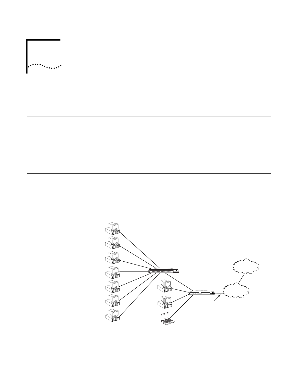
The ISDN LAN Modem is an easy to install, LAN to WAN modem. For the LAN, it
provides four 10BASE-T Ethernet connections— expandable to 25 connections.
Refer to Figure 1 for an example showing 10 connections by adding an 8-port
10BASE-T Ethernet hub. For WAN access, it provides a Basic Rate Interface (BRI)
ISDN port.
With the ISDN LAN Modem, small office and home office users can share remote
access to the Internet or to a remote office while continuing to network locally.
The primary application for the ISDN LAN Modem is:
■ Local networking with shared access to the Internet and/or a remote office
LAN.
Users can share access to the Internet while continuing to network locally.
Network Utilization
®
3 Com
Office
¤
Connect
Hub
Internet/Intranet
or
online service
PWR COLLPKT COAX1234
Alert
OfficeConnect
Hub 8 TPO
Port Status
5678
green = link OK, off = link fail, yellow = partition
1% 2% 3% 6% 12%25%50% 80%
Figure 1
OfficeConnect
ISDN LAN Modem
Tx
PWR
B2
ISDN
Alert
B1
Local Networking with Access to the Internet
Coll
LAN STATUS
OfficeConnect™
1
ISDN LAN Modem
2 3 4
®
3 Com
ISDN BRI line
Public telephone
network
Page 12

12 C
HAPTER
1: I
NTRODUCTION
Local Networking with
Access to a Remote
Office
Local Networking with
Access to the Internet
and a Remote Office
Users can share access to a remote office LAN while continuing to network locally.
Remote office
LAN
Figure 2
OfficeConnect
ISDN LAN Modem
PWR
B2
ISDN
Alert
B1
®
LAN STATUS
Coll
Tx
3 Com
OfficeConnect™
1
2 3 4
ISDN LAN Modem
Public telephone
network
ISDN BRI line
Local Networking with Access to a Remote Office
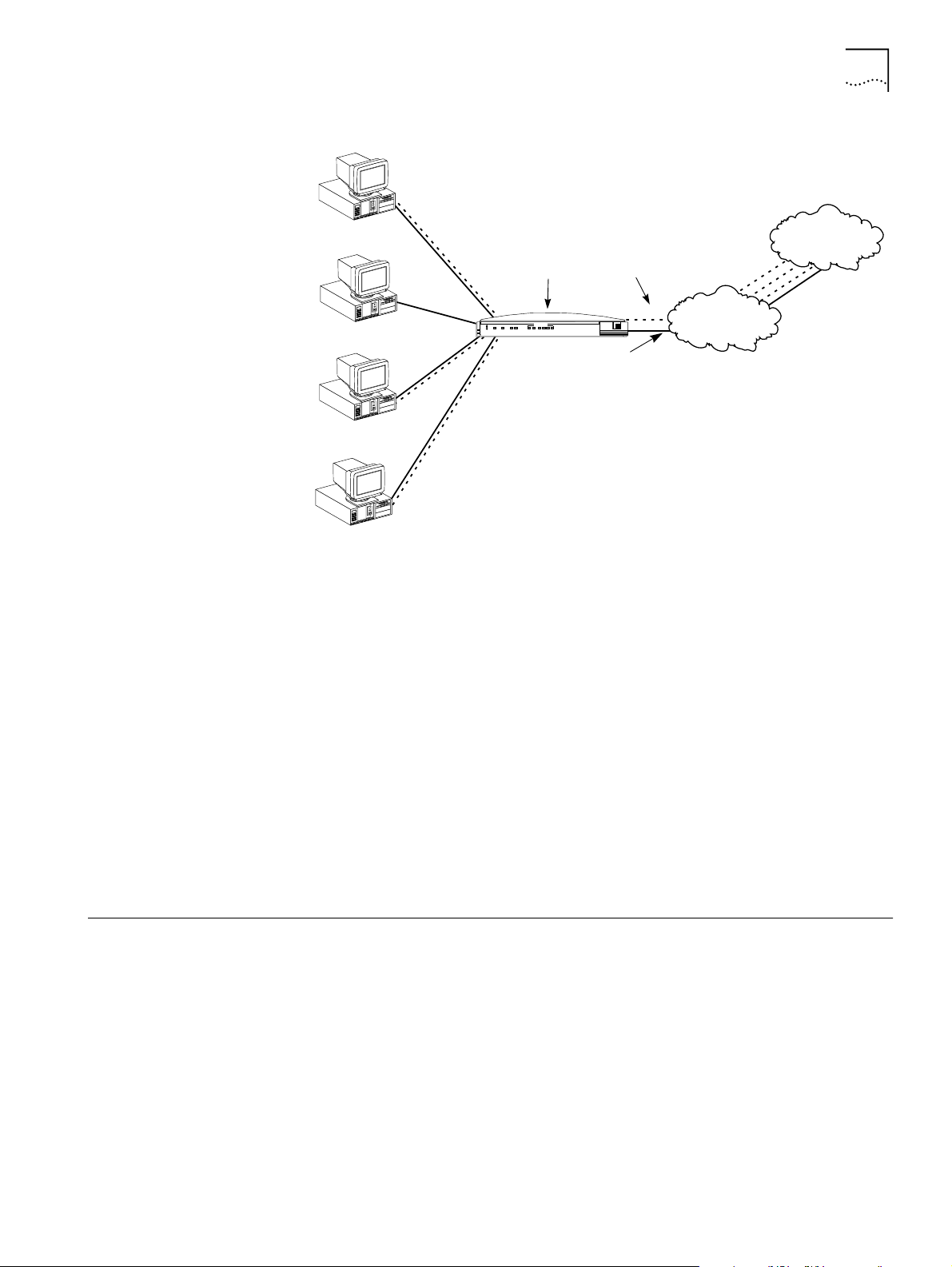
Users can share access to a remote office and the Internet while continuing to
network locally.
Figure 3
Internet/Intranet or
online service
OfficeConnect
ISDN LAN Modem
LAN STATUS
OfficeConnect™
1
2 3 4
Coll
Tx
PWR
B2
ISDN
Alert
B1
ISDN LAN Modem
®
3 Com
Public telephone
network
Remote office
LAN
ISDN BRI line
Local Networking with Access to a Remote Office and the Internet
Page 13

Features 13
Features
Ease of Installation and Use
■ SPID Wizard automatic configuration for telephone company switch and
service profile ID (SPID) numbers.
■ Web-based, point-and-click user interface for configuration and online help.
■ Automatic configuration verification with Internet connection through your
Internet Service Provider (ISP).
■ Firmware updates, user guides and technical notes available on the Web.
High Performance
■ Hi/fn™ LZS
Compression Control Protocol
Protocol
■ Multilink PPP (RFC 1990), which combines two PPP B channel calls to create a
®
compression, which conforms to these IETF RFCs:
(RFC 1962) and
PPP Stacker LZS Compression
(RFC 1974).
The PPP
virtual, single 128 Kbps network connection.
■ TollMizer, which places a single B channel or a Multilink PPP data call over a
voice connection, saving you the additional charge for a data call.
Connectivity
■ ISDN Basic Rate U interface.
■ Built in four-port 10BASE-T, 10 Mbps Ethernet hub. Up to 25 users can be
supported by connecting to an external eight port-hub.
■ Two analog voice ports.
■ Preferred Provider support which allows simultaneous connections to two
different ISPs.
Routing
■ IP Routing.
■ Dynamic or static IP addresses supplied by the ISP (WAN side).
■ WAN access for up to 25 local workstations on the LAN (10BASE-T).
■ Dynamic Host Control Protocol (DHCP) server functionality on the LAN, which
automatically assigns an IP address to a newly-attached computer on an IP
network.
■ Domain Name Service (DNS) server functionality for the LAN, which translates
the common, alphanumeric name of a device to the numeric IP address of a
device.
■ Network Address Translation (NAT) between LAN and WAN, which allows
multiple users on the LAN to share a WAN connection. Note that individual
email accounts may still be maintained at the ISP.
■ Multiplexing traffic from several computers to the same remote destination.
Page 14

14 C
HAPTER
1: I
NTRODUCTION
Bandwidth Management
■
Automatic call connection (also known as dial-on-demand routing).
■
Automatic disconnection of idle calls after a specified length of time.
■
Bandwidth on Demand using Bandwidth Allocation Control Protocol
(BACP)/Bandwidth Allocation Protocol (BAP) based on a specified threshold.
■
Dynamic bandwidth allocation (DBA), which allows you to place or receive a
voice or data call while a Multilink PPP call is active.
■
Manual call connection and disconnection.
Remote Management
■
Remote management using the same Web browser interface.
Voice Features
■
Two analog voice ports for using analog telephone equipment such as
touch-tone telephones, fax and answering machines, and analog modems.
■
Flexible call routing to the two analog ports.
■
Caller ID name and telephone display (supports Bellcore GR-30-CORE and
SR-TSV-002476 standards).
■
Caller ID Blocking
■
Call Waiting
■
Call Conference (Three-way calling)
■
Call Transfer
■
Call Forward
■
Distinctive Ringing
■
Voice Mail
Protocols
■
IETF PPP (RFC 1661, 1662, 1663).
■
IETF Multilink PPP (RFC 1990).
■
PPTP (Point-to-Point Tunneling Protocol— PPTP draft-ietf-pppext-pptp-02.txt).
■
IETF Password Authentication Protocol (PAP) (RFC 1334) and Challenge
Handshake Authentication Protocol (CHAP) security (RFC 1994).
■
MS-CHAP support (as defined in
Microsoft PPP CHAP Extensions. S. Cob, Rev. 1.3 March 1997
Network Working Group Information Memo:
including only
the functionality that keeps with IETF 1994).
■
IP address negotiation using IPCP (RFC 1332).
■
CCP (RFC 1962, 1974).
■
BACP/BAP (RFC 2125).
■
Network Address Translation between LAN and WAN (RFC 1631).
Page 15

Features 15
ISDN Standards and Interface
■ Basic Rate ISDN U interface with built-in NT1.
■ Full ISDN signaling support of National ISDN.
■ Compatibility with Lucent, Northern Telecom and Siemens switches.
Security
■ PAP, CHAP and MS-CHAP support on both single-channel and Multilink PPP
calls.
Upgradability
■ Flash memory for field firmware updates.
■ Firmware posted on 3Com’s Web site.
Diagnostics
■ LED status display.
■ Statistics display.
Warranty
■ Lifetime Limited Warranty (refer to the back of this User Guide for details).
Internet Applications and Games
Support for applications that use the User Datagram Protocol (UDP) and the
Transmission Control Protocol (TCP). The UDP protocol is used primarily by Internet
games.
Look for the latest list of Internet applications and games that interoperate with
the ISDN LAN Modem at
http://www.remoteaccess.3com.com/support/docs/lanmodem/welcome.html
Page 16

16 C
HAPTER
1: I
NTRODUCTION
Page 17
ISDN LAN M
ODEM
2
Connection Types
LAN Side Connection
F
UNCTIONALITY
D
ESCRIPTION
This chapter provides a description of the key functionality of the ISDN LAN
Modem. It includes the following topics:
■ Connection Types
■ Call Routing Protocol and IP Address Translation
■ Understanding Multilink PPP and Bandwidth on Demand
■ Understanding Dynamic Bandwidth Allocation
■ Understanding PPTP
For a basic understanding of ISDN and networking, refer to Appendix A.
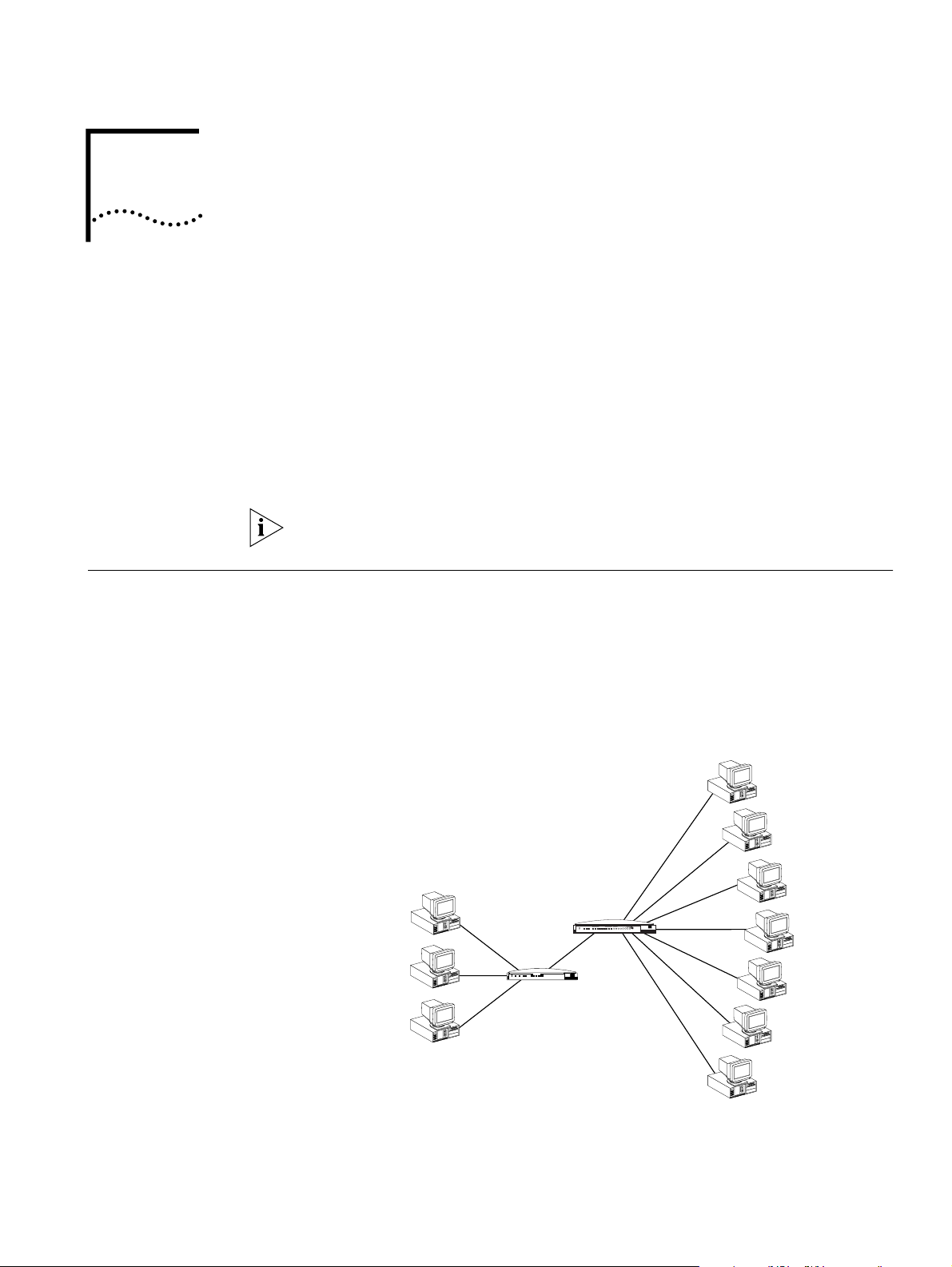
The ISDN LAN Modem provides LAN side and WAN side connections.
On the LAN side, up to four users can connect to the LAN Modem’s built in
Ethernet hub, or up to 25 users may connect to the LAN Modem via an external
user-supplied hub, enabling users to share files and printers and to use Internet
email. An example of ten workstation connections is shown in An example of 10
workstation connections is shown in Figure 4.
10 Mbps
Ethernet LAN
®
OfficeConnect
Hub 8 TPO
Port Status
Network Utilization
3 Com
Office
¤
5678
green = link OK, off = link fail, yellow = partition
1%2% 3% 6% 12%25% 50%80%
Connect
Hub
Figure 4
PWR COLLPKT COAX1234
Alert
LAN STATUS
3 Com
OfficeConnect®
1
Coll
2 3 4
Tx
PWR
ISDN
Alert
B2
B1
ISDN LAN Modem
®
OfficeConnect
ISDN LAN Modem
ISDN LAN Modem LAN Connection with 10 Workstations
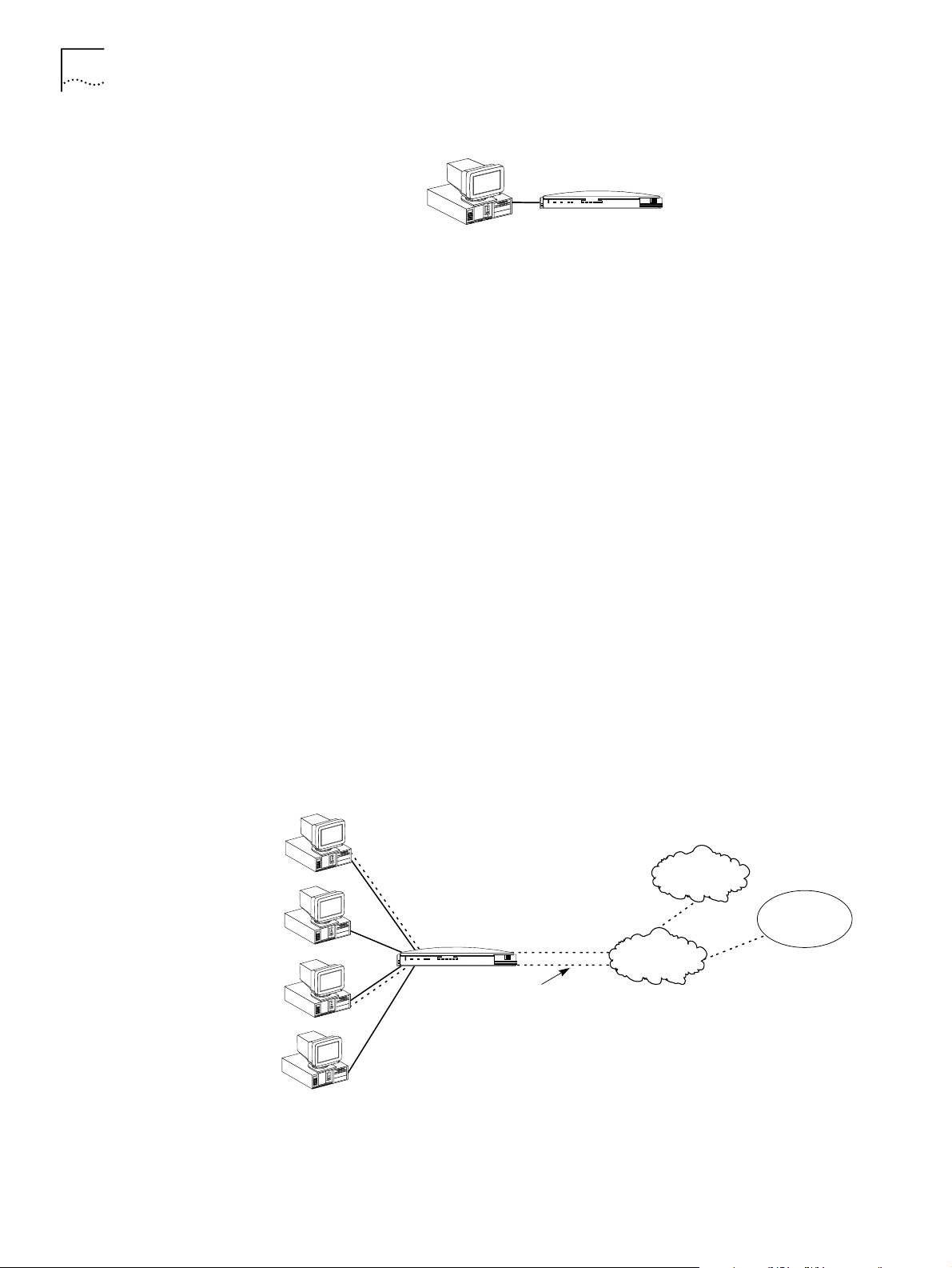
An example of a single connection is shown in Figure 5.
Page 18
18 C
2: ISDN LAN M
HAPTER
ODEM FUNCTIONALITY DESCRIPTION
WAN Side Connection
®
LAN STATUS
1
2 3 4
Coll
Tx
B2
B1
3 Com
Figure 5
OfficeConnect
ISDN LAN Modem
PWR
ISDN
Alert
ISDN LAN Modem Single Workstation Connection Example
Application Sharing over the LAN
Most operating systems such as Windows 98 and 95 and Macintosh provide the
capability for users on the LAN to share applications, files and printers among
computers. For example, if only one computer has a Web browser, the other users
on the LAN can use that Web browser to access the Internet. Note that speed will
likely be reduced when applications are shared. Refer to your operating system
documentation for instructions on setting up sharing between users on a LAN.
The ISDN LAN Modem allows users to connect to a WAN using either of the
following methods at one time.
■
Two separate connections to two different locations (one per B channel)
■
One high-speed Multilink PPP connection to a single location (combines both
B channels)
Once a WAN connection is established, up to 25 users can share that connection
and access the same location simultaneously. If you desire, you can also restrict
access to certain users.
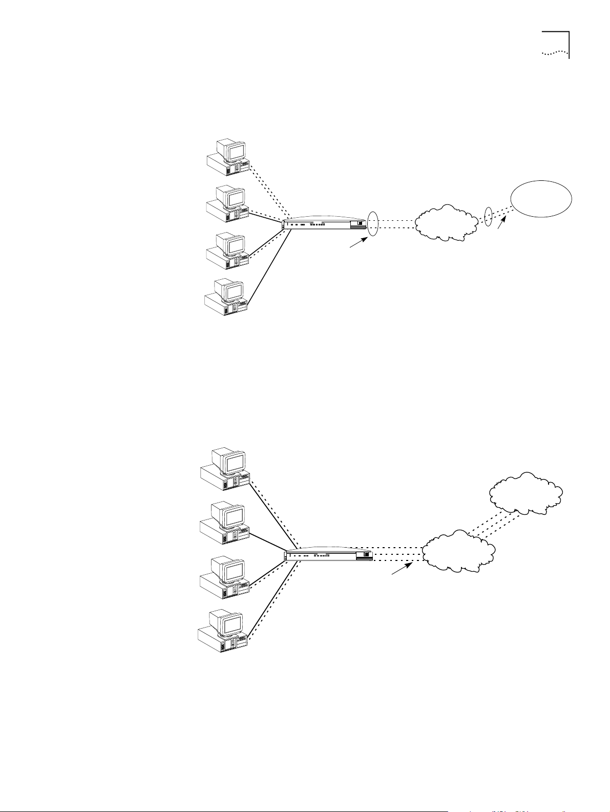
Two Separate
Connections to Different
Locations.
An ISDN BRI line has two B channels for transmitting data or voice. Because each
B channel is independent, you can connect to two different locations. Once the
connection is established, up to 25 users can share either connection. Figure 6
shows one user connecting to a remote office LAN while another connects to the
Internet.
Greg's PC
Marcia's PC
Peter's PC
Jan's PC
Figure 6
OfficeConnect
ISDN LAN Modem
PWR
ISDN
Alert
B2
B1
®
LAN STATUS
OfficeConnect™
1
2 3 4
Coll
Tx
ISDN LAN Modem
Greg—64 Kbps B1
3 Com
Peter— 64 Kbps B2
ISDN BRI line
Two Simultaneous Remote Connections to Different Locations
Internet/Intranet or
online service
Greg
64 Kbps B1
Public telephone
network
Peter
64 Kbps B2
Remote office
LAN
Page 19
Connection Types 19
OfficeConnect
®
ISDN LAN Modem
Public telephone
network
Remote office
LAN
Combining both
B channels with Multilink
provides a single 128 Kbps*
connection
PWR
ISDN
B1
B2
3 Com
Alert
Tx
Coll
1
2 3 4
LAN STATUS
64 Kbps B1
64 Kbps B2
128 Kbps B1 & B2
*Without compression.
Jerry's PC
Elaine's PC
George's PC
Cosmo's PC
OfficeConnect™
ISDN LAN Modem
Murray
Lou
Mary
PWR
ISDN
B1
B2
3 Com
Alert
Tx
Coll
1
2 3 4
LAN STATUS
OfficeConnect
®
ISDN LAN Modem
ISDN BRI line
Internet/Intranet or
online service
Mary's PC
Ted's PC
Lou's PC
Murray's PC
Mary
Murray
Lou
Public telephone
network
OfficeConnect™
ISDN LAN Modem
One High Speed
Connection to a Single
Location
Alternatively, the B channels can be combined using Multilink PPP to form one
high-speed connection to a single location. Figure 7 shows a single high-speed
connection to a remote office LAN.
Figure 7
One High-Speed Connection to a Single Location
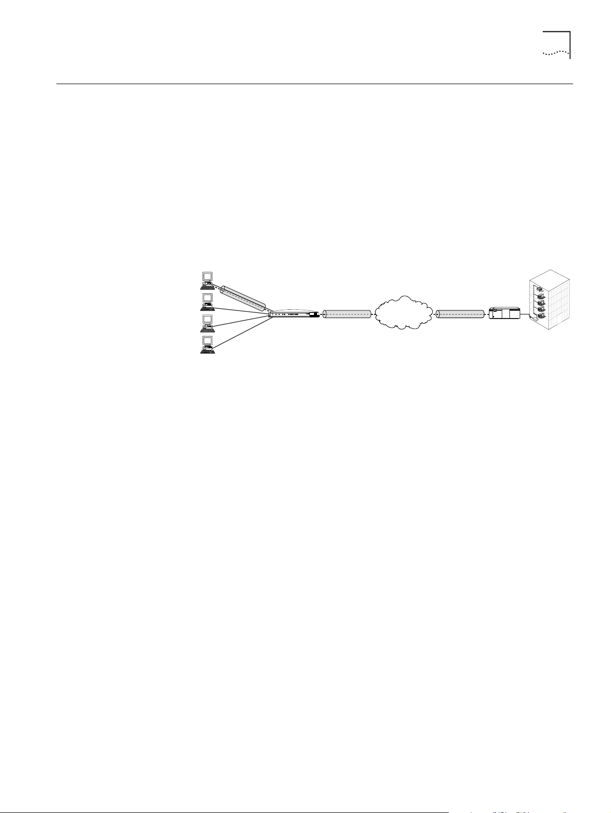
Up to 25 users can share a connection to the same location over the single
connection created by Multilink PPP. Figure 8 shows three users on the LAN
accessing the Internet through the same Internet provider and over the single
high-speed connection.
Figure 8
Shared Connection to the Same Location
Page 20

20 C
2: ISDN LAN M
HAPTER
ODEM FUNCTIONALITY DESCRIPTION
Call Routing Protocol and IP Address Transl ation
Placing a Call to a
Previously Defined
Destination
This section describes the call routing protocol used by the ISDN LAN Modem and
explains how IP addresses are translated.
To illustrate how the ISDN LAN Modem routes outgoing data calls, let us assume
that you have set up the following types of service providers.
■
A direct connection to an Internet Service Provider
■
A direct connection to a remote office LAN
■
A direct connection to a remote office LAN from which you can also access the
Internet
If all of those connection types are configured on the ISDN LAN Modem and are
associated with your computer, the following algorithm is performed for each of
the following scenarios.
Call Routing While No Other Calls Are Connected
If the ISDN LAN Modem has not established any calls to a remote destination and
you want to access the Internet from your computer, you simply launch your Web
browser (or whichever networking application you like). When the ISDN LAN
Modem receives the information packet requesting access to the WAN, it must
determine which connection type to use. The ISDN LAN Modem looks at the
destination Network ID (which comprises the destination IP address and subnet
mask) associated with the packet. If the Network ID of the packet matches the
Network ID of the remote LAN, with or without Internet access, then the call is
placed to the remote LAN. If it does not match the Network ID of the remote LAN,
with or without Internet access, then the call is routed to the direct ISP connection.
Once the connection is established, any authorized user on the LAN can use this
connection. The ISDN LAN Modem will translate each individual user’s IP address
into a single, shared IP address (assigned by the remote location), thereby allowing
up to 25 users to access the same remote location.
The following example shows three users sharing a connection to the Internet and
depicts the IP translation as it occurs in the ISDN LAN Modem.
Page 21
Understanding Multilink PPP and BACP/BAP 21
198.6.1.1
198.6.1.1
198.6.1.1
192.168.1.5
192.168.1.2
192.168.1.4
OfficeConnect® ISDN LAN Modem
192.168.1.1
ISDN BRI line
Internet/Intranet or
online service
PWR
ISDN
B1
B2
3 Com
Alert
Tx
Coll
1
2 3 4
LAN STATUS
Rob's PC
192.168.1.2
Laura's PC
192.168.1.3
Buddy's PC
192.168.1.4
Sally's PC
192.168.1.5
198.6.1.1
IP address
assigned by ISP
Translates PC IP
addresses to IP
address assigned
by ISP
ISDN BRI line
Public telephone
network
OfficeConnect™
ISDN LAN Modem
Understanding Multilink PPP and BACP/BAP
Figure 9
IP Address Translation
Call Routing While One Call Is Already Connected
If the ISDN LAN Modem has established a call to a remote destination, for
instance, to an ISP, and the ISDN LAN Modem receives more packets, then the
ISDN LAN Modem looks at the Network ID of the packets for proper routing. For
example, if the Network ID of the packets matches that of the remote LAN and
that connection has not yet been established, then the call is placed and the
connection is made. If the Network ID does not match and the call type is an
Internet access call, then the packets are routed to the ISP.
Note that the ISDN LAN Modem always calls the first configured ISP. If you have
configured a second ISP and want to use that one instead, from the ISDN LAN
Modem’s configuration home page go to
Workstation Parameters
, select your
computer, and then associate only the ISP that you want to use.
What is Multilink PPP?
Multilink PPP is a protocol which combines multiple point-to-point protocol (PPP)
connections to form a single high-bandwidth channel. With a BRI line, Multilink
PPP combines the two 56 Kbps or 64 Kbps ISDN B channels, creating a virtual,
single connection of up to 112 Kbps or 128 Kbps.
What is BACP/BAP?
BACP/BAP is used in conjunction with the Multilink PPP feature and is transparent
to the user (that is, it will not be visible to you as it occurs in the background). You
need not configure this functionality. When Multilink PPP is negotiated, the
Bandwidth Allocation Control Protocol (BACP) negotiates with the peer
equipment to determine whether the peer supports BAP. If the peer supports BAP
Page 22

22 C
2: ISDN LAN M
HAPTER
ODEM FUNCTIONALITY DESCRIPTION
and agrees to use BAP, then the Bandwidth Allocation Protocol (BAP) negotiates
the addition and removal of the second B channel with the peer equipment based
on a user-defined threshold. A key advantage of BACP/BAP is that it provides a
higher probability of establishing a Multilink PPP call during high traffic conditions
by providing a specific telephone number for the second B channel to call.
Multilink PPP Configuration Options
When configuring Multilink PPP, you can choose one of the following options
from the ISDN LAN Modem’s Service Provider Parameters window.
■
Use One B Channel
When this option is configured, only one B channel is used to connect to this
service provider. Multilink PPP is thereby disabled and BACP/BAP is therefore
not used.
■
Use Two B Channels
When this option is configured, both B channels are always used to connect to
this service provider, regardless of the amount of traffic over each
B channel. Note that when this option is selected, the DBA feature does not
work because both B channels are being used. To use both DBA and Multilink
PPP, select the option
Add Second B Channel as Required
.
Understanding Dynamic Bandwidth Allocation
■
Add Second B Channel As Required
When this option is configured (referred to as bandwidth on demand) only one
B channel is used to connect to this service provider, and the second
B channel is automatically added only when the amount of traffic on the first
B channel reaches a threshold you define.
In order for you to use Multilink PPP, the destination you are calling must also
support Multilink PPP. For example, if you are trying to dial in to the Internet, your
ISP must also support Multilink PPP in order to successfully place a Multilink PPP
call. If you attempt to place a Multilink PPP call and the location you are calling
does not support Multilink PPP, then a single B channel PPP connection is
established.
Dynamic Bandwidth Allocation is used in conjunction with Multilink PPP on
demand (to use DBA, you should choose
Add Second B Channel As Required
when you configure Bandwidth Allocation). The Dynamic Bandwidth Allocation
feature allows you to automatically and temporarily remove one of the B channels
and use it either to place or receive a call (voice or data) without disturbing the
original call. The only effect on the original call is that it is reduced from a Multilink
PPP call to the speed of one B channel.
Once the interrupting call ends, that B channel is automatically returned to the
Multilink PPP call. Although throughput is reduced while the interrupting call is
active, the reliability of the Multilink PPP call is maintained.
Page 23
Understanding VPNs and PPTP 23
From the Edge to the Heart
of the Network.
3
C
om
POWER
ISDN
Alert
B1
B2 TX COLL 1 2 3 4
3 Com
LAN STATUS
ISDN LAN Modem
3C892
OK
Internet Service
Provider
LAN Modem
Tunnel
terminator
Corporate
network
Understanding VPNs and PPTP
Virtual private networks (VPN) are private, secure networks created in public
networks such as the Internet. A VPN is essentially a secure, private tunnel within
the Internet. Since VPN calls are placed through a local ISP, they eliminate long
distance charges that would occur from directly dialing to a remote private
network.
One of the protocols which enables a VPN to be created is PPTP. The PPTP protocol
allows for multiple workstations to establish a secure multi-protocol connection to
a remote, private network via a single, locally-dialed ISP account as shown in
Figure 10. Any networking protocols such as IP, IPX and NetBEUI can be supported
transparently through the tunnel. While the ISDN LAN Modem supports PPTP, it
does not play an active role in creating or terminating a tunnel.
Figure 10
Connection to an Remote Private Network via an ISP
Setting Up the Server
Side of the Tunnel
Setting Up the Client
Side of the Tunnel
The main steps for creating a VPN are as follows. Each step is explained in detail in
subsequent sections.
■ Set up the server side of the tunnel connection
■ Set up the client side of the tunnel connection
■ Initiate a tunnel between client and server using your client software
In order to establish a tunnel, the client side must be able to dial into a PPTP tunnel
server on the remote private network such as 3Com’s NETBuilder, PathBuilder, and
Total Control Hub as well as Microsoft’s Windows NT server version 4.0 or later. If
you use Windows NT 4.0, then Service Pack 3 or greater and RAS must be
installed. Also, the protocols required for the private network must be installed on
the PPTP tunnel server. It is recommended that an experienced network
administrator set up the server side. Note that protocols required for the private
network must be installed on each PPTP tunnel client as well as the PPTP tunnel
server.
In order to establish a tunnel, the client side must have PPTP tunnel client software
such as Windows Dial-Up Networking version 1.2 or higher which includes the
required software VPN adapter or Windows NT operating system with Service Pack
3, or Network TeleSystem’s TunnelBuilder™ VPN software for Windows 3.11 and
Macintosh operating systems. This software should reside on all workstations that
wish to create a tunnel to the tunnel server. Follow instructions provided for
installation and set up.
Page 24

24 C
2: ISDN LAN M
HAPTER
ODEM FUNCTIONALITY DESCRIPTION
For Windows Dial-Up Networking Users
If you are using Windows Dial-Up Networking version 1.2 or higher, the basic set
up steps are as follows. (Refer to Windows user documentation for details.)
■
Install the PPTP protocol
■
Create a RAS phone book entry for the VPN
A RAS phone book entry is similar to other phone book entries except there is
an IP address in the Phone number field. Once the Phone book entry is
complete, you can double-click the icon to dial into a server that supports PPTP
via any ISP.
Note that protocols required for the private network must be installed on each
PPTP tunnel client as well as PPTP tunnel server.
Establishing a Tunnel via
the ISDN LAN Modem
As with PPP, no configuration is required on the LAN Modem to use PPTP.
However, you must have an ISP configured on the LAN Modem.
Once the client side and server side are configured, you are ready to create a
tunnel. The steps required for creating a tunnel vary depending on which client
software you are using. Refer to the user documentation provided with your PPTP
software to determine how to establish a tunnel. For instance, if you are using
Windows Dial-Up Networking version 1.2 or higher, double-click the phone book
entry for the VPN.
Once you attempt to create a tunnel, the ISDN LAN Modem detects this attempt
and automatically places a call to your ISP. Once the call is connected, a tunnel is
established between your workstation and the tunnel server.
You are ready to access a remote private network LAN as if you were connected
locally. Each workstation that wishes to have access to the remote private LAN will
need to create its own tunnel.
For more information, refer to:
http://www.remoteaccess.3com.com/support/docs/lanmodem/
welcome.html For specific instructions on how to configure a VPN adapter in
Windows 98, 95 or Windows NT, refer to Microsoft’s Web site at
http://www.microsoft.com. and then enter PPTP in the search field.
Page 25

H
ARDWARE
D
ESCRIPTION AND
3
Package Contents
Before You Install the ISDN LAN Modem
I
NSTALLATION
The ISDN LAN Modem package includes:
■ OfficeConnect ISDN LAN Modem
■ Power cable with an AC wall transformer
■ RJ -11 ISDN telephone cable
■ 10BASE-T Ethernet cable
■ 3Com Companion Programs CD-ROM
■ OfficeConnect ISDN LAN Modem Getting Started Guide
■ Rubber feet and stacking clips
To install, configure and use the ISDN LAN Modem successfully, you must have the
following:
■ Correct ISDN service installed at your location with an available ISDN RJ-11 or
RJ-45 outlet. If you have not yet ordered ISDN service, refer to Appendix E.
■ A JavaScript-enabled and frames-capable Web browser. A Web browser is
provided on the 3Com Companion Programs CD-ROM. (For more information
refer to Appendix B.) If you use a different Web browser, make sure that it
supports frames such as Netscape 2.1 and later and Internet Explorer 3.0 and
later.
If you already have a version of the Internet Explorer Web browser installed and
would like to install a later version, you should first uninstall the previous version. If
you are asked to replace the older files, it is recommended that you do so.
■ A personal computer with TCP/IP and Ethernet connectivity that meets UL
standards in the United States or is certified to CSA standards in Canada.
For a PC, a 386 or higher processor is recommended and a 10BASE-T
■
Ethernet card is required.
For an Apple Macintosh computer, system 7.6 or later operating system and
■
Open Transport (provided as part of system 7.5). Built-in Ethernet
connectivity is provided through an Apple Ethernet port in all Power
Macintosh computers.
TCP/IP is provided as part of the Windows 98, 95, NT and Macintosh System
■
7.6 and later operating systems. For Windows 3.11 users, TCP/IP software is
provided on the 3Com Companion Programs CD-ROM.
You do not have to have available storage space on your computer’s hard drive
because nothing is copied as part of the ISDN LAN Modem installation. If you want
to copy any programs or documents from the CD-ROMs, ensure that you have
available hard disk space.
Page 26

26 C
HAPTER
3: H
ARDWARE DESCRIPTION AND INSTALLATION
Front Panel LED Description
The front panel provides the following LEDs.
Alert
Figure 11
ISDN
OK
B1
B2 TX COLL 1 2 3 4
POWER
ISDN LAN Modem Front Panel
LAN STATUS
ISDN LAN Modem
3C892
3 Com
The functions of the front panel LEDs are described in Table 4. These front panel
LEDs show whether or not the unit is functioning properly and indicate the status
of the activity over the 10BASE-T and ISDN ports.
Table 4
LED Color Description
Alert Amber
POWER Green
ISDN
OK
B1/B2 Amber or
Tx Green
Coll Amber
Ports1—4 Green
Front Panel LED Indicator Definitions
Operational Status. Lit during power-on self-test diagnostic or
after pressing the reset button.
Off indicates the unit has passed the diagnostic tests and is
working properly.
Flashes (four times per second) if one or more of the diagnostics
have failed or after the unit is placed in firmware download mode
and is waiting for a firmware upgrade.Flashes (once per second) to
indicate there are pending voice mail messages.
Power Indicator. Remains lit as long as power is supplied to the
unit.
Green D Channel Status. Indicates the status of the ISDN physical
network interface and D channel.
Remains lit once the physical ISDN interface and D channel
signaling are synchronized.
Off indicates the physical ISDN interface is not synchronized or is
disconnected.
Flashes when the physical interface attempts synchronization or
when the ISDN D channel parameters have changed.
B1/B2 Channel Activity. Green indicates a data call in progress.
Green
Amber indicates a voice call in progress. If a call is in a dialing state,
the LED flashes. When the call is disconnected, the LED goes off.
Ethernet Transmit Status. Flashes green when data is being
transmitted to the Ethernet LAN from the ISDN LAN Modem.
Off indicates no data is being transmitted to the Ethernet LAN
from the ISDN LAN Modem.
Ethernet Collision Status. Flashes amber when some collisions
are taking place on the Ethernet LAN.
Off indicates no collisions are taking place on the Ethernet LAN.
Ethernet LAN Port Status. On indicates the unit detects the
Ethernet link integrity signal from an attached computer and
operation is normal.
Flashes when the LAN Modem is receiving data on that port.
Off indicates the unit does not detect the Ethernet link integrity
signal. The Ethernet cable may not be properly connected or the
cable may be the wrong polarity.
Page 27

Installing the ISDN LAN Modem 27
RESET
10-18 VDC
0.8 A MAX
ISDN
1 PHONE 2
LAN
Power
Connector
Reset Button
Two Analog
Telephone Ports
Four Ethernet
10Base-T Connectors
ISDN
BRI Interface
4
3
1
2
Back Panel Connector
Description
The back panel provides the following components.
Figure 12
ISDN LAN Modem Back Panel
From left to right the back panel consists of the following.
Power: Connect the power module cable to this port.
■
Reset: Press this button for no more than a couple of seconds if you have to
■
reset the unit. This causes the software to restart while maintaining your
configuration profile which includes service provider information and ISDN line
telephone numbers.
Two Analog Telephone Ports: You can connect analog equipment such as a
■
fax machine or telephone to these ports.
Four 10BASE-T Ethernet Ports: Connect the computers to these ports or
■
another Ethernet hub to add up to 25 users.
Installing the ISDN LAN Modem
Before You Begin
ISDN Basic Rate Interface Port: Connect the ISDN cable to this port.
■
This section describes how to do the following.
■ Install the ISDN cable
■ Connect to a 10BASE-T Ethernet LAN
■ Install analog equipment
■ Install the power cable
Before you begin, you will need the following in addition to the ISDN LAN Modem
which was provided in the package:
■ RJ-45 (8-pin) to RJ-11 (6-pin) cable labeled ISDN which was provided in the
package.
■ 10BASE-T Ethernet cable (8-pin to 8-pin connectors) labeled Ethernet which
was provided in the package. It is recommended that you use the cable
provided. If, however, you choose to use another cable it must be a
straight-through 10BASE-T Ethernet cable. It cannot be a crossover cable.
■ Power adapter provided (you must use the power adapter provided in the
package).
Page 28

28 C
HAPTER
3: H
ARDWARE DESCRIPTION AND INSTALLATION
Installing the ISDN Cable
To install the ISDN cable:
Connect the RJ-45 (8-pin) connector end of the ISDN cable to the port labeled
1
ISDN on the back panel, as shown in Figure 13.
ISDN
1 PHONE 2
RESET
10-18 VDC
0.8 A MAX
Figure 13
Connect the RJ-11 (6-pin) connector end of the RJ-45/RJ-11 ISDN cable to the
2
ISDN Cable Connection
RJ-11 or RJ-45 ISDN wall jack.
CAUTION: An NT1 (that is, a network termination device) is built into the ISDN
LAN Modem. Never connect the ISDN LAN Modem ISDN port to a standard analog
telephone jack or to an external NT1 device. Make sure that the ISDN cable is
connected directly to the ISDN jack.
Connecting to a
10BASE-T Ethernet Port
To connect a computer to the ISDN LAN Modem, do the following.
Insert one end of the 10BASE-T Ethernet cable into one of the four LAN ports on
1
the back of the ISDN LAN Modem, as shown in Figure 14.
ISDN
1 PHONE 2
RESET
10-18 VDC
0.8 A MAX
Figure 14
Insert the opposite end of the cable into your computer’s 10BASE-T Ethernet port.
2
10BASE-T Ethernet LAN Connection
Page 29
Installing the ISDN LAN Modem 29
Connecting to Another
Ethernet Hub
CAUTION:
You should only have one computer physically connected to the ISDN
LAN Modem during configuration. Once you complete the configuration process,
connect any other computers you would like to have on the LAN and then power
cycle each computer. If the newly-added computers cannot communicate with the
ISDN LAN Modem, refer to “Evaluating Symptoms and Solutions” in Chapter 9.
You can connect to another Ethernet hub to allow up to 25 users to access the
WAN. Instructions for adding another Ethernet hub to allow 10 users, a more
common scenario, is as follows.
Before You Begin
In addition to an external 10BASE-T Ethernet hub, you will need a 10BASE-T
Ethernet cable, which may have been provided with the additional hub. If the hub
to which you are connecting your LAN Modem does not have an MDI/X switch,
you must use a crossover cable.
Insert one end of the 10BASE-T Ethernet cable into one of the four LAN ports on
1
the back of the ISDN LAN Modem, as shown in Figure 15.
ISDN
10-18 VDC
0.8A MAX
+
-
RESET
1 PHONE 2
+
10-18 VDC
-
0.8A MAX
Figure 15
Insert the opposite end of the cable into a 10 BASE-T Ethernet port on the other
2
10BASE-T Hub-to-Hub Connection
87654321
MDI/MDIX
Ethernet hub.
If you are connecting to an OfficeConnect Hub 8/TPO, insert the opposite end of
the Ethernet cable into port 8 and then set the MDI/X switch to MDI (that is,
pressed in). Make sure that the LED associated with that Ethernet port is lit. If it is
not, try changing the MDI/X switch setting.
Page 30
30 C
HAPTER
3: H
ARDWARE DESCRIPTION AND INSTALLATION
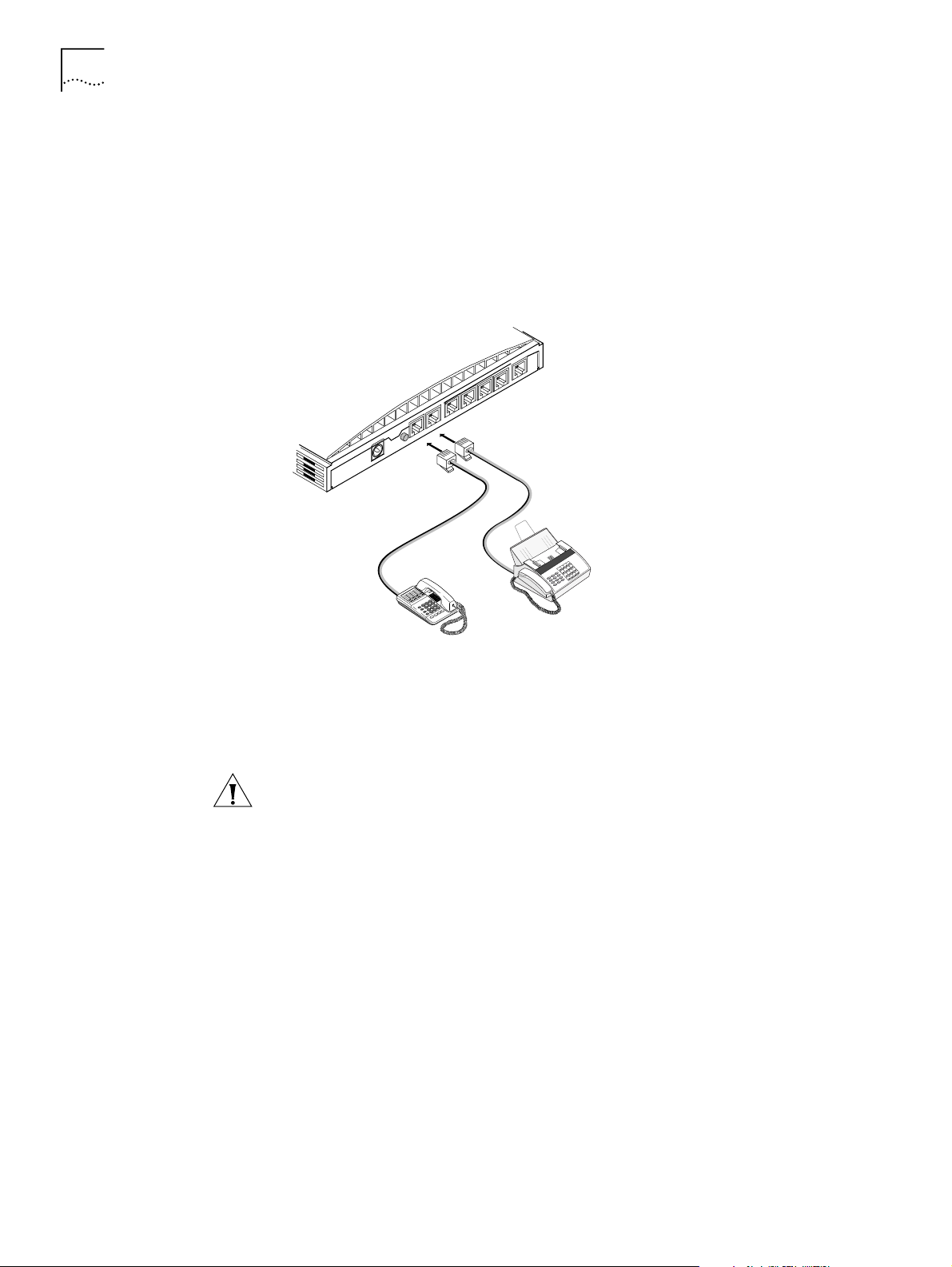
Installing Analog
Equipment
You can connect an analog touch-tone telephone, answering machine, fax
machine, or external analog modem to the ISDN LAN Modem. You will need an
RJ-11 to RJ-11 cable that is supplied with the analog device for each analog phone
port connection.
To install an analog device:
Insert one end of an RJ-11 cable into one of the two analog ports labeled Phone
1
on the back of the ISDN LAN Modem, as shown in Figure 16.
ISDN
1 PHONE 2
RESET
10-18 VDC
0.8 A MAX
Figure 16
Insert the other end of the RJ-11 cable into the appropriate RJ-11 port on the
2
Analog Equipment Connection
analog device.
If you have another analog device to install, repeat steps 1 and 2.
3
CAUTION: The ISDN LAN Modem is designed to operate with touch-tone
telephones that collectively do not exceed a ringer equivalence number (REN) of
three per analog phone port. The ISDN LAN Modem is designed to provide power
(25 mA loop current per phone port) and ringing for these devices on up to 61
meters (200 feet) of AWG 26 or heavier AWG wiring. Although the ISDN LAN
Modem may function satisfactorily at longer cable distances with more than two
attached telephones, proper operation at longer cable distances is not guaranteed
in all situations.
Specialized telephone equipment such as speaker phones that draw large
amounts of power may not work on the ISDN LAN Modem’s Phone port. Because
these devices do not conform to the power specification of the touch-tone
telephone standard, their operation is not guaranteed.
Page 31

Wall Mounting the ISDN LAN Modem 31
Installing the Power
Cable
To install the power cable:
Connect the ISDN LAN Modem power module cable to the 10-18 VDC power
1
connector on the back panel of the ISDN LAN Modem, as shown in Figure 17.
ISDN
1 PHONE 2
RESET
10-18 VDC
0.8 A MAX
Figure 17
Plug the other end of the power module into a surge-protected standard 110 VAC
2
Power Cable Connection
wall outlet.
The indicator LEDs on the front panel flash momentarily as the unit undergoes a
power-up self-test diagnostic. The Power LED remains lit.
This completes the ISDN LAN Modem installation. In addition to the Power LED,
the ISDN LED remains lit indicating the line is configured and ready for use. The
LAN port LEDs associated with workstations connected to those ports also remain
lit indicating the LAN Modem can communicate with the workstation(s).
If you do not have TCP/IP installed and set up on your computer, refer to
Chapter 4, “Setting Up TCP/IP for Windows and Macintosh.” If you already have
TCP/IP installed and set up on your computer, refer to Chapter 5, “Configuring the
ISDN LAN Modem.”
Wall Mounting the ISDN LAN Modem
There are two slots on the underside of the ISDN LAN Modem which are used for
wall mounting. You will need two suitable screws. Ensure that the wall you are
going to use is smooth, flat, dry and sturdy. Make two screw holes which are
5 7/8 in (150 mm) apart. Insert the screws into the wall, leaving their heads 1/8 in
(3 mm) clear of the wall surface.
Remove any connections to the ISDN LAN Modem and position the unit over the
screw heads. When the unit is in line, gently push it onto the wall and move it
downward to secure. When making connections, be careful not to push the ISDN
LAN Modem up and off the wall.
Page 32

32 C
HAPTER
3: H
ARDWARE DESCRIPTION AND INSTALLATION
WARNING: Only wall mount single units. Do not wall mount stacked OfficeConnect
units.
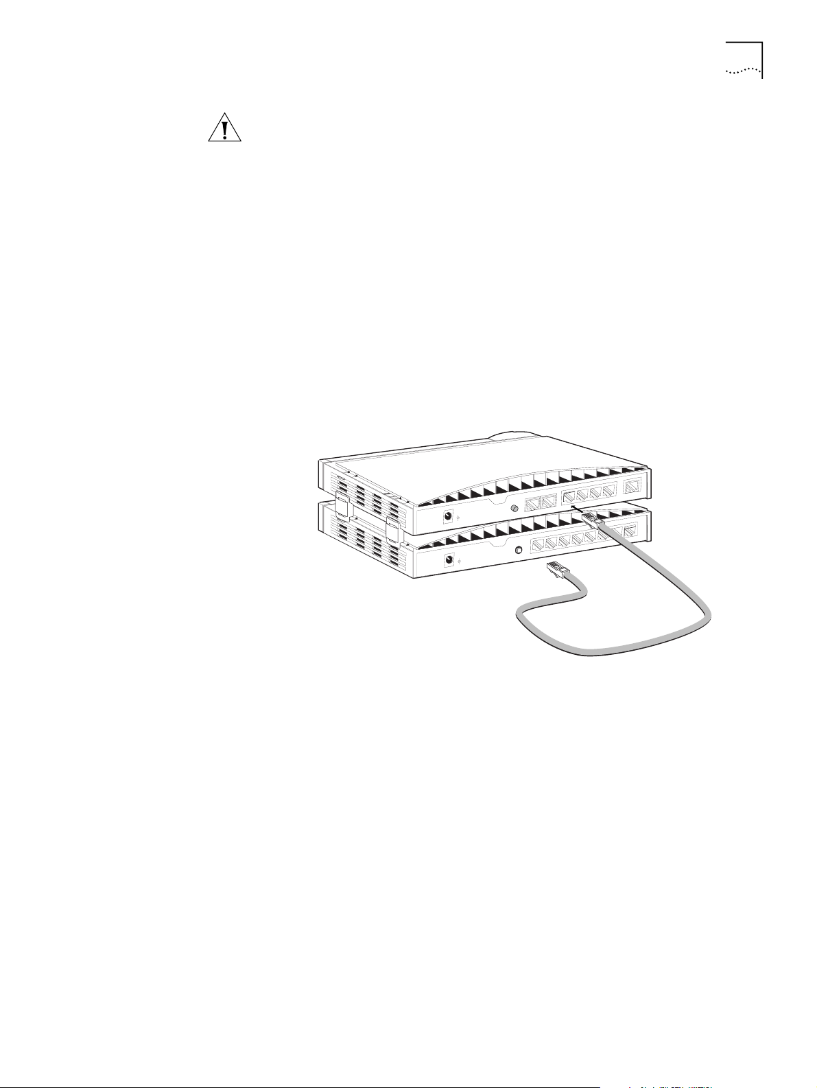
Using Rubber Feet and Stacking Clips
Attach the feet to the marked areas at each corner of the underside of your ISDN LAN
Modem to stabilize your ISDN LAN Modem and prevent sliding.
Use the four clips to stack OfficeConnect units together. You can stack up to four
units. Stack small units above large units.
1. Place your existing unit on a flat surface.
Your clips fit in these positions on the side
of the unit.
2. Position a clip over one of these holes
and push it until it clicks into place.
Repeat this for the other clip position on
the same side.
3. Keeping the front of the units aligned,
rest the bottom of the new unit on the
clips’ spikes. Push the clips firmly into
the new unit until they click into place.
Small unit
Use these
holes
Large unit
Use these
holes
Spike
Figure 18
Using Stacking Clips
Page 33

S
ETTING
UP TCP/IP
FOR
W
INDOWS
4
TCP/IP Setup Using Windows 98 and Windows 95
AND
This chapter describes how to set up the Windows and Macintosh operating
system (OS) TCP/IP stack. Your computer must have a TCP/IP stack in order to use
the ISDN LAN Modem. If you already have TCP/IP installed and set up on your
computer, then go on to Chapter 5. These instructions vary depending upon
which operating system you are using. Refer to the appropriate section.
■ TCP/IP Setup Using Windows 98 and Windows 95
■ TCP/IP Setup Using Windows NT 4.0
■ TCP/IP Setup Using Mac OS 7.6 or later
■ TCP/IP Setup Using Windows 3.11
TCP/IP is provided as part of the standard Windows 98 and Windows 95 operating
systems. To set up TCP/IP for the ISDN LAN Modem, do the following.
You may be prompted for your installation disks or CD-ROM.
M
ACINTOSH
From the Control Panel, double click Network.
1
The Network dialog box appears.
Figure 19
Click Add.
2
Network Dialog Box
The Select Network Component Type dialog box appears.
Page 34

34 C
HAPTER
4: S
ETTING UP
TCP/IP
FOR WINDOWS AND MACINTOSH
Figure 20
Select
3
Select Network Component Type Dialog Box
Protocol
and then click
Add
.
The Select Network Protocol dialog box appears.
Figure 21
From the Manufacturers list box, select
4
Protocols list box, select
Click OK.
5
Select Network Protocol Dialog Box
Microsoft
TCP/IP
.
, and then from the Network
Select the Configuration tab.
6
The Network Configuration dialog box appears.
7
Select
TCP/IP
and then click
Properties
.
If you have multiple TCP/IP entries, select
with the ISDN LAN Modem.
for the Ethernet card associated
TCP/IP
Page 35

TCP/IP Setup Using Windows 98 and Windows 95 35
Figure 22
8 From the TCP/IP Properties dialog box, select the
Figure 23
9 Most users need to select
Network Dialog Box
TCP/IP Properties Dialog Box
Obtain an IP address automatically
IP Address
tab.
because most LANs
use dynamic IP addresses. If your LAN uses static IP addresses, enter the IP address
and subnet mask. (You can obtain this information from your system administrator
or ISP.)
10 Select
Advanced
and then check the box to set TCP/IP as the default protocol.
Page 36

36 C
HAPTER
4: S
ETTING UP
TCP/IP
FOR WINDOWS AND MACINTOSH
TCP/IP Setup Using Windows NT 4.0
Figure 24
Click OK to close the TCP/IP Properties dialog box.
11
Click OK to close the Network dialog box.
12
Restart Windows 98 or 95 to let these changes take effect.
13
Advanced Parameters of TCP/IP Properties
Windows NT 4.0 provides TCP/IP as part of its standard operating system. If you
have not already set up TCP/IP, do the following.
You will need your Windows NT 4.0 installation CD-ROM.
From the Control Panel, double-click
1
Network
.
The Network dialog box appears.
Select the
2
Protocols
tab, as shown in Figure 25.
Page 37

TCP/IP Setup Using Windows NT 4.0 37
Figure 25
3 Click
Windows NT Protocols Configuration Window
Add
.
The Select Network Protocol dialog box appears as shown in Figure 26.
Figure 26
4 Select
Select Network Protocol Dialog Box
TCP/IP Protocol
and then click OK.
The following message appears.
Figure 27
DHCP Message Box
5 Select the appropriate response for your network.
6 You are then prompted to insert your installation CD-ROM. Insert the Windows NT
4.0 CD ROM and then click
Continue
.
For users who have Remote Access Service (RAS) installed on their PC, after the
appropriate files are copied to your PC, a message box asks whether or not you
would like TCP/IP installed for RAS. If you select
you want to access remotely and then click
Close
, you must select the device
Ye s
.
7 After the appropriate files are copied to your PC, you will see TCP/IP Protocol listed
in the Network Protocols group box, as shown in Figure 28.
Page 38

38 C
HAPTER
4: S
ETTING UP
TCP/IP
FOR WINDOWS AND MACINTOSH
Figure 28
Click
8
Network Protocols Group Box
Close.
The Microsoft TCP/IP Properties window appears, as shown in Figure 29.
Figure 29
From the Adapter drop down list box, select the Ethernet card that is connected to
9
Microsoft TCP/IP Properties Window
the ISDN LAN Modem.
If this LAN uses dynamic IP addresses, select
10
server
. If this LAN uses static IP addresses, enter the IP address and subnet mask.
Click OK.
11
Ye s
12
Click
to restart your PC and allow the changes to take effect.
Obtain an IP address from a DHCP
Page 39

TCP/IP Setup Using Mac OS 7.6 or later 39
TCP/IP Setup Using Mac OS 7.6 or later
If you are using Macintosh operating system version 7.6 or later, Open Transport
(OT) PPP is provided and installed by default. If you did not install OT PPP when
you installed your system software, perform a custom installation of your system
software and install OT PPP version 1.1 or later.
To set up TCP/IP for Mac, do the following.
From the Apple menu, select
1
Control Panels
and then select
TCP/IP
.
The TCP/IP dialog box appears.
Figure 30
Select
2
If this LAN uses dynamic IP addresses, select
3
TCP/IP Dialog Box for Macintosh Computers
Ethernet
or
Ethernet built in from
the Connect via drop down list box.
Using DHCP Server
from the
Configure drop-down list box. If this LAN uses static IP addresses, select
from the Configure drop-down list box and then enter the IP address.
Manually
Page 40

40 C
HAPTER
4: S
ETTING UP
TCP/IP
FOR WINDOWS AND MACINTOSH
TCP/IP Setup Using Windows 3.11
Setting Up TCP/IP Using
MS TCP
If you are using Windows 3.11, a TCP/IP stack is not provided as part of the
operating system. If you do not have a TCP/IP stack, you can use MS TCP which is
provided on the
3Com Companion Programs
CD-ROM.
To set up MS_TCP, do the following.
Install MS_TCP, located on the
1
3Com Companion Programs
CD-ROM, onto your
hard drive.
From the Program Manager, click
2
Figure 31
From the Network group box, click
3
Program Manager Group Box
Network
.
Network Setup
.
Figure 32
From the Network Setup dialog box, click the
4
From the Network Drivers dialog box, click
5
Select
6
From the Install Driver dialog box, enter the path to the MS TCP directory.
7
Network Group Box
Unlisted or Update Protocol
Drivers
Add Protocol
and then click OK.
button.
.
For example, if you installed MS TCP on your C: drive in a directory called MSTCP,
you would enter C:\MSTCP.
Select MS TCP/IP-32.X and then click OK to install.
8
The protocol is added to the list as shown in Figure 33.
Page 41

TCP/IP Setup Using Windows 3.11 41
Figure 33
9 After the installation is complete, click
10 Click
Network Setup Dialog Box
OK
.
Close
.
11 From the MS TCP/IP Configuration dialog box, check the
Configuration
check box and then click OK.
12 Restart your PC to allow the changes to take effect.
Enable Automatic DHCP
Page 42

42 C
HAPTER
4: S
ETTING UP
TCP/IP
FOR WINDOWS AND MACINTOSH
Page 43

C
Launch
Web Browser
Run
SPID Wizard
Verify
Configuration
Run
ISP Wizard
ONFIGURING THE
ISDN LAN
5
Typical Configuration
M
ODEM
This chapter describes how to configure the ISDN LAN Modem for the typical
configuration. The typical configuration covers the basic setup and includes what
most users need to get up and running. It provides instructions for setting up your
ISDN line and connecting to the Internet. If you followed the instructions in the
Getting Started Guide, you have already set up the typical configuration. To see if
there are any additional changes you would like to make, you may want to look
over Chapter 6, “Advanced Configuration.”
The configuration windows shown in this chapter may differ slightly from what is
displayed on your computer.
The typical configuration covers the following main steps.
Before You Begin
You Should Have Done
This
Figure 34
Make sure that you have done the following.
Before you configure the ISDN LAN Modem, you should have already done the
following:
■ Installed the hardware as described in Chapter 3, “Hardware Description and
Installation.”
■ Installed and set up TCP/IP on all computers you intend to connect to the ISDN
LAN Modem. If TCP/IP is not installed and set up, refer to Chapter 4.
Main Steps for Typical Configuration
Page 44

44 C
HAPTER
5: C
ONFIGURING THE
You Should Have This
Information
ISDN LAN M
ODEM
CAUTION: You should only have one computer physically connected to the ISDN
LAN Modem during configuration. Once you complete the configuration process,
connect any other computers you would like to have on the LAN and then power
cycle each computer. If the newly-added computers cannot communicate with the
ISDN LAN Modem, refer to “Evaluating Symptoms and Solutions” in Chapter 9.
■
Telephone number(s) for your ISDN line provided by your telephone company.
■
If you want to set up a connection to an ISP, you will also need the telephone
number to call for access to your ISP, as well as your user name, password and
DNS address (if your service provider requires a DNS address to be configured).
Determine Whether You
Use Dynamic or Static IP
Addresses
Your setup procedure will vary depending upon whether you are using a dynamic
or a static IP address.
A static IP address is a permanent, manually-assigned address recognized by a
remote server, such as a corporate LAN or an ISP. By default, your ISDN LAN
Modem dynamically assigns an IP address to each computer. If you have been
accessing a remote server via a static IP address prior to installing your ISDN LAN
Modem, you may be required to perform additional configuration steps. The first
step is to determine your static versus dynamic IP addressing scenario.
If you determine that your computer has a static IP address, refer to “Setting Up
Your Computer If You Have a Static IP Address.” If your computer has a dynamic IP
address, you may begin configuring the ISDN LAN Modem directly. Refer to
“Configuring the ISDN LAN Modem for the Typical Configuration.”
Determine your IP address type as follows:
For Windows 98, 95 and NT 4.0 Users:
■
Settings
and then
Control Panel
. Double-click
From the
Start
Network
menu, select
. Select
TCP/IP
for the
Ethernet card you will attach to the ISDN LAN Modem and then click
Properties
. Select the
address automatically
from a DHCP server
dynamic IP address. If the radio button labeled
IP Address
tab. If the radio button labeled
(Windows 98 and 95) or labeled
Obtain an IP address
Obtain an IP
(Windows NT 4.0) is selected, your computer has a
Specify an IP address
is
selected, your computer has a static IP address.
For Mac Users:
■
TCP/IP
. Choose
From the Apple menu, open
Ethernet
Ethernet built in
or
Control Panels
. Double-click
from the Connect via
drop-down list box, if it is not already chosen. If the Configure drop down
list box is set to
Using DHCP Server,
then you are on a dynamic network and
are ready to continue directly with “Installing the ISDN LAN Modem.” If
Configure is not set to
Using DHCP Server
and you have specific values
listed in any of the following fields: IP Address, Subnet mask, Router
address, or Name server addr., then your computer has a static IP address.
For Windows 3.11 Users:
■
Network
the
Setup
program group icon. Double-click the
Drivers
button. Highlight the
. If Enable DHCP Configuration is checked, then your computer has a
From the Program Manager, double-click the
Network Setup
Microsoft TCP/IP - 32.X
icon. Click
entry and click
dynamic IP address. If an IP address is entered in the IP Address box, then
your computer has a static IP address.
Page 45

Before You Begin 45
Setting Up Your
Computer If You Have a
Static IP Address
If your computer has a static IP address, you must verify and possibly change some
settings on your computer before you begin the configuration procedure. The
ISDN LAN Modem must be your gateway and one of your DNS servers. Follow the
procedure in the appropriate section to make sure that this is the case. Note that if
your computer has a dynamic IP address, this configuration would occur
automatically and you can go on to “Configuring the ISDN LAN Modem for the
Typical Configuration.”
These instructions assume that the LAN Modem configuration is set the factory
default. If you are moving the LAN Modem from a different LAN, reset the LAN
Modem before you begin. To do so, connect a telephone to one the LAN Modem
phone ports and then enter **3266# from the keypad.
For Windows 98 and 95 Users
From the Start menu, select
1
Double-click
2
Network
Settings
and then select
If you have multiple TCP/IP entries, select
and then
.
TCP/IP
TCP/IP
Control Panel
.
for the Ethernet card associated
with the ISDN LAN Modem.
3
Click
Properties
and then select the
Gateway
tab and write down the first IP
address in the Installed Gateways box.
If nothing is entered in the Installed Gateway list, enter an IP address that does not
belong to any workstation on your LAN, but is in the subnet that you have chosen
for your LAN. Write this IP address down for later use.
Click the
4
In the DNS Server Search Order edit box, enter the gateway IP address you wrote
5
DNS Configuration
down as part of the previous step and then click
Click OK to close the TCP/IP Properties box.
6
Click OK to close the Network control panel.
7
tab.
Add
.
You are asked to restart your computer.
Click OK.
8
For Windows NT 4.0 Users
From the
1
Double-click
2
Highlight
3
Click the
4
menu, select
Start
Network
and then click
TCP/IP
IP Address
Settings
and then
and then select the
Properties
Control Panel
Protocols
.
tab.
.
tab and then select the Ethernet card associated with the ISDN
LAN Modem from the Adapter drop-down list box.
Write down the IP address in the Installed Gateways box.
5
Click the
6
Click
7
8
Add
In the TCP/IP DNS Server box, enter the gateway IP address you wrote down
previously and then click
DNS
.
tab.
Add
.
10
9
Click
Click
to close the Microsoft TCP/IP Properties dialog box.
OK
to close the Network Control Panel box.
OK
Page 46

46 C
HAPTER
5: C
ONFIGURING THE
ISDN LAN M
ODEM
You are asked to restart your computer.
Click OK.
11
For Macintosh Users
From the Apple menu, open
1
Control Panels
. Double-click
TCP/IP
.
Choose
2
The Configure drop down list box should be set to
Ethernet
from the Connect via drop-down list box, if not already chosen.
Manually
if you are on a static
network.
Note the series of numbers entered in the Router address box. Write this number
3
down.
Enter this number into the Name server addr. box. (If you already have existing
4
address(es) listed, add the new address below the last entry.)
Choose
5
When asked to save your changes, do so by choosing
6
File
and
Close
.
Save
.
You may want to rename this configuration so that your previous configuration is
not overwritten.
For Windows 3.11 Users
From the Program manager, click
1
From the Network group box, click
2
From the Network Setup dialog box, click the
3
From the Network Drivers dialog box, double-click
4
Uncheck
5
Write down the number in the Default Gateway field.
6
Enable Automatic DHCP Configuration
Network
.
Network Setup
.
Drivers
button.
Microsoft TCP/IP-32
.
.
Click OK.
7
Restart your PC to allow the changes to take effect.
8
You are now ready to install your ISDN LAN Modem. Refer to “Configuring the
ISDN LAN Modem for the Typical Configuration” to continue.
Page 47

Configuring the ISDN LAN Modem for the Typical Configuration 47
Configuring the ISDN LAN Modem for the Typical Configuration
To configure the ISDN LAN Modem for the typical configuration, do the following.
If you are using static IP addressing, you may need the IP address which you
recorded previously in the “Setting Up Your Computer If You Have a Static IP
Address”section.
Launch your Web browser.
1
The ISDN LAN Modem attempts to use its default IP address to communicate with
the computer. If communication cannot be established, the ISDN LAN Modem will
change its default IP address. If this occurs, the ISDN LAN Modem will reset itself
and then function as described in this section.
Regardless of the start page to which your Web browser is set, your Web browser
will go to the ISDN LAN Modem configuration setup.
A welcome message appears, as shown in Figure 35.
Figure 35
Click
2
Initial SetUp Welcome Window
Continue
.
A message box appears and indicates that the ISDN LAN Modem clock is being
synchronized to the date and time on your workstation.
The Set Password window appears. This password is used to guard access to the
ISDN LAN Modem’s configuration program. If you would like to restrict access to
the configuration program, select a password and record it in a safe place.
Page 48

48 C
HAPTER
5: C
ONFIGURING THE
ISDN LAN M
ODEM
Figure 36
Enter a password in the Password field and then enter the same password in the
3
Set Password Window
Password (repeat) field to confirm it. If you do not wish to enter a password, leave
the fields empty.
4
Click
.
Submit
A message box indicates that your password has been set. The SPID Wizard
window appears.
Figure 37
SPID Wizard Window
Page 49

Configuring the ISDN LAN Modem for the Typical Configuration 49
If you have not ordered your ISDN line, click
Abort
and then Click
Yes
to confirm
that you want to abort the SPID Wizard program. The ISDN LAN Modem
configuration main page appears. After you have an ISDN line installed, refer to
“Setting Up Your ISDN Line Manually”
for instructions on configuring your ISDN
connection manually.
Enter the first telephone number for your ISDN line.
5
If you have another telephone number associated with your ISDN line, enter it in
6
the second telephone number field. Otherwise, leave this field blank.
7
Click
Continue
.
The SPID Wizard configures the switch type and SPIDs of your ISDN line. When the
SPID Wizard is done, the ISP Wizard appears
Figure 38
If you do not want to use the ISP Wizard, click
configuration main page appears. Refer to
Providers”
In the Name field, enter the name of your ISP.
8
In the Telephone Number field, enter the telephone number of your ISP.
9
ISP Wizard Window
Abort
. The ISDN LAN Modem
“Setting Up Additional Service
for instructions on configuring your ISP connection manually.
If you want to enter another telephone number to connect to your ISP or change
these settings, refer to “Editing Service Provider Profiles” after you have
completed this typical installation procedure.
In the User ID and Password fields, enter your user ID and password for your ISP
10
account.
If your ISP requires a DNS address, enter it in the DNS Address(es) field.
11
Specify how you want the bandwidth allocated for this connection.
12
Page 50

50 C
HAPTER
5: C
ONFIGURING THE
ISDN LAN M
ODEM
■
Use one B channel:
When selected, one B channel is used to connect to
this service provider.
■
Add second B channel as required:
When selected, the second B channel
is added when the first B channel reaches a certain threshold. The threshold
default is 60%. To change the threshold default, refer to “Changing Data
Call Parameters” in Chapter 6. The second B channel is temporarily
removed when you place or answer another call.
■
Use two B channels:
When selected, both B channels are used to connect
to this service provider (that is, always use Multilink PPP). Note that this
prevents another call, data or voice to be placed or received as there is no
available bandwidth (that is, the second B channel cannot be temporarily
removed).
Specify the B channel rate or select
13
TollM iz er
.
Leave the B channel rate set to 64 Kbps unless your telephone company and the
locations to which you will be connecting only support 56 Kbps.
TollMizer makes a 56 Kbps data call over a voice circuit allowing you to save the
typical cost difference between a voice and data call. Note that the destination you
are calling must also support this feature (also referred to as Switched 56
Permissive or Data Over Voice). Check with your telephone company and ISP to
make sure that they support TollMizer.
Continue
14
Click
.
A call is launched to your ISP. A congratulations message appears when you
successfully connect to your ISP. This verifies the correct configuration of your ISDN
line and ISP connection.
This configuration covers the typical parameters needed to connect to your ISP.
There are additional parameters for this ISP connection which have been set to a
typical default. These parameters include Domain Name, Compression, NAT, and
WAN Link IP Address. In addition, you can enter a second telephone for
connection to your ISP. For information on these parameters and instructions for
changing their default values, refer to “Editing Service Provider Profiles.”
15
Click
to connect to the ISDN LAN Modem Web site where you should
Continue
register the product and view the ReadMe file which contains the latest
information.
For all the latest, up to date information about your ISDN LAN Modem, visit
http://www.remoteaccess.3com.com/support/docs/lanmodem/welcome.html
If you cannot access a Web site and your computer has a static IP address, refer to
“Configuring a Static IP Address on the ISDN LAN Modem.” If you experience any
other problems, refer to Chapter 9, “Troubleshooting and Maintenance.”To return
to the LAN Modem’s main configuration page, click
Configure Modem
from the
Web page.
Page 51

Configuring the ISDN LAN Modem for the Typical Configuration 51
Configuring a Static IP
Address on the ISDN
LAN Modem
If you followed the steps in “Configuring the ISDN LAN Modem for the Typical
Configuration” and were not able to connect to a Web site and your computer
has a static IP address, there may be an incompatibility between the IP address on
your computer and the IP address on the ISDN LAN Modem. To correct this, do the
following.
Enter the following URL in your Web browser:
1
From the ISDN LAN Modem’s main configuration page click on the ISDN LAN
2
http:/ /3c om.oc. la nmodem/
Modem icon in the illustration.
The LAN (Ethernet) Parameters page appears.
In the IP Address field, enter the default gateway address you entered as described
3
in “Setting Up Your Computer If You Have a Static IP Address”.
4
Click
Submit
.
The ISDN LAN Modem will reset.
5
Click
Refresh
from your Web browser’s menu bar.
The Enter Password window appears.
Enter your password and then click
6
Submit
.
The ISDN LAN Modem’s main configuration page appears.
Click the
7
ISP Wizard
button.
You will see the information you entered previously.
8
Click
Continue
.
A call is launched to your ISP. A congratulations message appears when you
successfully connect to your ISP. This verifies the correct configuration of your ISDN
line and ISP connection.
This configuration covers the typical parameters needed to connect to your ISP.
There are additional parameters for this ISP connection which have been set to a
typical default. These parameters include Domain Name, Compression, NAT, and
WAN Link IP Address. In addition, you can enter a second telephone for
connection to your ISP. For information on these parameters and instructions for
changing their default values, refer to “Editing Service Provider Profiles” on
page 64.
9
Click
Continue
to go to the ISDN LAN Modem Web site where you should register
the product and view the ReadMe file which contains the latest information.
For all the latest, up to date information about your ISDN LAN Modem, visit
http://www.remoteaccess.3com.com/support/docs/lanmodem/welcome.html
Page 52

52 C
HAPTER
5: C
ONFIGURING THE
ISDN LAN M
ODEM
ISDN LAN Modem Main Page
The ISDN LAN Modem main page is shown in Figure 39. From this page you can
access configuration parameters as well as place and receive calls.
Bookmark this page for easy access. Alternatively, if you are using the ISDN LAN
Modem Web browser, click
Figure 39
ISDN LAN Modem WebWizard Main Page
Configure Modem
from the
Links
menu bar.
The ISDN LAN Modem main configuration page, also called the WebWizard,
provides links to configuration, dialing, statistics screens and help. Once you click
to a configuration screen, the bottom frame provides help for that configuration
as well as links to other help topics. There are links from the illustration as well as
links from the buttons listed in the left vertical frame.
Links from the
Illustration
By clicking on the icons in the illustration, you can jump to the following locations.
■
Service Providers:
Jumps to the Service Providers page where you can
configure a connection to an ISP or a private network.
■
Workstations:
Jumps to the Workstation Selection page where you can view a
workstation’s IP address and can change its associations with service providers.
■
ISDN Parameters:
Jumps to the ISDN Parameters page where you can
manually configure ISDN parameters if you prefer not to run the SPID Wizard.
Also, supplementary voice services are configurable from this page.
■
LAN Parameters:
Jumps to the LAN Parameters page where you can configure
Ethernet parameters for the ISDN LAN Modem.
■
Data Call Parameters:
Jumps to the Data Call Timeout Parameters page.
From here you may set inactivity timers, which allow calls to be disconnected
due to network inactivity, keeping telephone usage and Internet access costs
down.
■
Call Routing:
Jumps to the Voice Call Routing page where you can configure
how you would like voice calls routed to the analog equipment such as a
telephone or fax machine attached the ISDN LAN Modem’s Phone ports.
■
Current Call Status:
Jumps to the Call Statistics page where the latest call
information is displayed.
Page 53

ISDN LAN Modem Main Page 53
Links from the Buttons
■
Home:
■
SPID Wizard:
■
ISP Wizard:
Jumps to the main configuration page of the ISDN LAN Modem.
Activates the SPID Wizard if you need to run it again.
Allows you to configure an ISP. If you already configured an ISP
using the ISP Wizard, and then you run ISP Wizard again, the latest ISP will
overwrite the previous one. To add a second ISP, go to the Service Providers
page.
■
Manual Calling:
Jumps to the Manual Calling page where you can connect
and disconnect calls.
■
Statistics:
Jumps to the Statistics page where you can view statistics regarding
the following: system, ISDN, current call, last call and service provider.
■
Maintenance:
Jumps to the Maintenance page where you can reset the ISDN
LAN Modem as well as place the ISDN LAN Modem in firmware download
mode in order to download the latest firmware.
■
Password:
Jumps to the Password page restrict access to the LAN Modem
WebWizard by configuring a password.
Context-sensitive help is available in the bottom frame of each configuration
screen. To increase the size of the help frame, drag the pane separator up.
This chapter covers the typical configuration steps required for a basic
understanding of your ISDN LAN Modem functionality. For further configuration
options, refer to Chapter 6, “Advanced Configuration.”
Page 54

54 C
HAPTER
5: C
ONFIGURING THE
ISDN LAN M
ODEM
Page 55

6
A
DVANCED
This chapter describes how to configure advanced settings for the ISDN LAN
Modem. For instance, setting up a connection to a private network such as a
remote office LAN, and changing default settings. You should follow the typical
configuration steps first so that you can have your ISDN line parameters set up
before you configure the advanced parameters.
Specifically, this section provides instructions for doing the following.
■ Setting up additional service providers
■ Editing service provider profiles
■ Associating service providers with workstations
■ Configuring LAN parameters
■ Changing data call parameters
■ Changing voice call routing
C
ONFIGURATION
Before you Begin
■ Reserving DHCP addresses
■ Changing your password
■ Locking the configuration
The configuration windows shown in this chapter may differ slightly from that
displayed on your computer.
Before you begin advanced configuration, access the ISDN LAN Modem’s
WebWizard. To access the WebWizard (also referred to as the ISDN LAN Modem
main configuration page), do the following.
If you are using the ISDN LAN Modem custom Web browser, click Configure
Modem to configure additional parameters. If you are not using the ISDN LAN
Modem Web browser, enter:
http://3com.oc.lanmodem
/
Page 56

56 C
HAPTER
6: A
DVANCED CONFIGURATION
Setting Up Additional Service Providers
A service provider is a location outside of your LAN that you would like to access
from your LAN, such as an ISP for access to the Internet or a private network such
as a remote office LAN. You can define up to four service providers (that is, remote
destinations) on the ISDN LAN Modem.
This section describes how to do the following:
■
Differentiate between an ISP and private network
■
Set up a connection to an ISP
■
Set up a connection to a private network
■
Associate computers on the LAN with selected service providers
■
Edit service provider profiles
If you set up a connection to an ISP as part of the typical (that is, initial) setup (via
the ISP Wizard), then you already have one service provider defined. Because this is
considered a typical configuration, some default values have been assumed. For
example, the connection to an ISP is associated with all of the computers
connected to your LAN. In other words, all computers on the LAN can connect to
that ISP and therefore the Internet. You may want to review the profile for this ISP
to see if you want to make any changes. For instructions, refer to “Editing Service
Provider Profiles.”
ISP versus Private
Network
There are two types of service providers you may configure, an ISP and a private
network. A description of each follows.
When to Select ISP
Choose ISP when you want to set up a direct connection to the public Internet (via
an Internet Service Provider) as shown in Figure 40.
Internet or
online service
ISDN
LAN Modem
ISDN outlet
Figure 40
Direct Connection to an ISP
Page 57

Setting Up Additional Service Providers 57
Direct Connection to Private Network Direct Connection to Private Network
& ISP via Private Network
When to Select Private Network
Select private network when you want to connect directly to a remote, private
LAN such as a corporate network, shown in Figure 41. For instance, if you want to
dial into your main office from home in order to access the servers at your office
for e-mail, printing, and so on, then select private network as the type of service
provider you want to configure. If the private network you are dialing into
provides the option of accessing the Internet and you want to be able to reach the
Internet through your corporate LAN (as opposed to through a direct connection
to an ISP), then choose that option when configuring your private network
parameters.
Setting Up a Connection
to an ISP
Figure 41
Remote office LAN
ISDN
LAN Modem
ISDN outlet
Direct Connection to a Private Network
Internet or
online service
ISDN
LAN Modem
ISDN outlet
Remote office LAN
This section describes how to set up your ISDN LAN Modem for access to the
Internet.
Before You Begin
Before you begin, you will need the following information from your ISP:
■ Telephone number(s) you must dial to access this ISP
■ User ID and password
■ DNS IP address(es)
This information is required only if your ISP does not provide the IP address
dynamically.
Setting Up a Connection to the Internet
To set up a connection to an ISP, do the following.
From the ISDN LAN Modem main page, click the
1
Select
2
New (Internet Service Provider)
Service Providers
from the drop down list box.
graphic.
Page 58

58 C
HAPTER
6: A
DVANCED CONFIGURATION
Figure 42
Click
3
ISP Service Provider Selection Window
Select
.
The Internet Service Provider Parameters window appears.
Figure 43
In the Name field, enter a name for this remote destination, such as the name of
4
ISP Parameters Window
the ISP. You may want to add an additional description if you have more than one
account with this particular ISP.
In the Telephone Number 1 field, enter the telephone number you must dial in
5
order to reach your ISP.
Page 59

Setting Up Additional Service Providers 59
In the Alternate Number field, you can either enter an alternative number or, if
6
required by your ISP, a second telephone number to establish a Multilink PPP call.
To enter a second, alternative telephone number for your ISP that will be
automatically dialed (if, for example the first number is busy) select
Alternate
then enter the telephone number in the Number field.
Some ISPs may require that you dial two telephone numbers to establish a
Multilink PPP call. If so, select
Multilink
from the drop down list box and then enter
the telephone number in the Number field.
Under Security, enter your User ID and Password.
7
Under DNS IP Address(es), if your ISP uses static IP addresses (that is, your ISP does
8
not supply these addresses when a dial up connection is established), enter the
primary DNS IP address of your ISP in the Primary field. If there is a secondary
address, enter it in the Secondary field.
Specify Bandwidth Allocation.
9
and
■
Use one B channel:
When selected, one B channel is used to connect to
this service provider.
■
Add second B channel as required:
When selected, the second B channel
is added when the first B channel reaches a certain threshold. The threshold
default is 60%. To change the threshold default, refer to “Changing Data
Call Parameters.” The second B channel is temporarily removed when you
place or answer another call.
■
Use two B channels:
When selected, both B channels are used to connect
to this service provider (that is, always use Multilink PPP). Note that this
prevents another call, data or voice to be placed or received as there is no
available bandwidth (that is, the second B channel cannot be temporarily
removed).
Under Miscellaneous, specify the B channel rate or select TollMizer.
10
Leave the B channel rate set to 64 Kbps unless your telephone company and the
locations to which you will be connecting require 56 Kbps.
TollMizer makes a 56 Kbps data call over a voice circuit, allowing you to save the
typical cost difference between a voice and data call. Note that the destination you
are calling must also support this feature (also referred to as Switched 56
Permissive or Data Over Voice). Check with your telephone company and ISP to
make sure that they support TollMizer.
Under Miscellaneous, leave the default, NAT enabled, unless you are certain you
11
want to disable it. With NAT enabled, the ISDN LAN Modem translates IP
addresses between the computers on the LAN and the ISP, allowing all LAN users
access to a single ISP. Only disable NAT when static IP addresses are provided by
your ISP for users on the LAN.
Under Miscellaneous, if the ISP to which you want to connect does not assign a
12
dynamic IP address and wants you to use a static IP address, enter the IP address
and the subnet mask in the WAN link fields. Otherwise, leave these fields empty.
Under Miscellaneous, indicate whether or not you would like to use compression
13
when transferring data by selecting the appropriate radio button.
For Allow Automatic Call Initiation, leave the default setting, which is
14
Yes
If you select No, you will have to manually launch a call to this service provider
every time you want to connect. You may want to set this field to No if your calls
.
Page 60

60 C
HAPTER
6: A
DVANCED CONFIGURATION
are being connected unintentionally as a result of packets generated by your
workstations.
Setting Up a Connection
to a Private Network
For Enable Intelligent NAT, leave the default setting, which is
15
Yes,
in order for the
LAN Modem to better support Internet applications and games.
The ISDN LAN Modem delivers all unsolicited TCP/UDP packets to the workstation
that is currently communicating with the remote host that has generated these
packets. If you set this field to No, all unsolicited TCP/UDP packets are delivered to
the default workstation.
In the Default Workstation for Incoming Packets field, specify the workstation to
16
which all unsolicited TCP/UDP packets should be delivered.
Note that if the Enable Intelligent NAT field is set to
Yes
, the ISDN LAN Modem
first attempts to deliver the unsolicited TCP/UDP packets to the workstation that is
currently communicating with the remote host that has generated these packets.
Only if no such workstation is found are the packets delivered to the specified
default workstation.
Submit
Click
17
If you would like to configure a connection to another ISP, repeat steps 1—17. You
18
can configure up to a total of four remote destinations
.
.
If you want to password protect the configuration profile of the ISDN LAN
Modem, refer to “Locking and Unlocking the Configuration”.
This section describes how to set up your ISDN LAN Modem for access to a private
network such as a remote office LAN.
Before You Begin
Before you begin, you will need the following information from your MIS
department:
■
Telephone number(s) you must dial to access this private network
■
User ID and password
■
IP address/subnet mask of the remote LAN you want to access
In addition, you may need the following, depending on your particular network
setup. Check with your network administrator.
■
Domain name of the remote LAN you want to access
■
DNS IP address(es)
■
WAN Link IP address
Setting Up a Connection to a Remote LAN
To set up a connection to a remote LAN, do the following.
From the ISDN LAN Modem main page, click the
1
Service Providers
graphic.
The Service Provider Selection window appears.
Page 61

Setting Up Additional Service Providers 61
Figure 44
2 Select
Private Network Service Provider Selection Window
New Private Network
from the drop-down list box and then click
The Private Network Parameters window appears.
Select
.
Figure 45
Private Network Parameters Window
Page 62

62 C
HAPTER
6: A
DVANCED CONFIGURATION
3
4
5
6
7
In the Name field, enter a name for this remote destination, such as the name of
the location of the office. You may want to add an additional description if you
have more than one account with this private network.
In the Telephone Number 1 field, enter the telephone number you must dial in
order to reach this remote office.
In the Alternate Number field, you can either enter an alternative number or, if
required by this private network, a second telephone number to establish a
Multilink PPP call.
To enter a second, alternative telephone number for this private network that will
be automatically dialed (if, for example the first number is busy) select
Alternate
and then enter the telephone number in the Number field.
If your private network requires that you dial two telephone numbers to establish
a Multilink PPP call, select
Multilink
from the drop-down list box and then enter
the telephone number in the Number field.
Under Security, enter your User ID and password.
Under DNS IP Address(es), if this private network uses static IP addresses (that is,
these IP addresses are not supplied when a dial-up connection is established) enter
the primary DNS IP address of your private network in the Primary field. If there is
a secondary address, enter it in the Secondary field.
Specify Bandwidth Allocation.
8
■
Use one B channel:
When selected, one B channel is used to connect to
this service provider.
■
Add second B channel as required:
When selected, the second B channel
is added when the first B channel reaches a certain threshold. The threshold
default is 60%. To change the threshold default, refer to “Changing Data
Call Parameters.” The second B channel is temporarily removed when you
place or answer another call.
■
Use two B channels:
When selected, both B channels are used to connect
to this service provider (that is, always use Multilink PPP). Note that this
prevents another call, data or voice to be placed or received as there is no
available bandwidth (that is, the second B channel cannot be temporarily
removed).
Under Private Network Parameters, enter the IP address, subnet mask and domain
9
name of the private network. You must enter an IP address and subnet mask.
Under Miscellaneous, if you want to be able to access the Internet from this
10
private network, select the
Yes, I want to access the Internet
radio button.
Otherwise, select the No radio button.
Under Miscellaneous, specify the B channel rate or select TollMizer.
11
Leave the B channel rate set to 64 Kbps unless your telephone company and the
locations to which you will be connecting require 56 Kbps.
TollMizer makes a 56 Kbps data call over a voice circuit, allowing you to save the
typical cost difference between a voice and data call. Note that the destination you
are calling must also support this feature (also referred to as Switched 56
Permissive or Data Over Voice). Check with your telephone company and ISP to
make sure that they support TollMizer.
Page 63

Setting Up Additional Service Providers 63
Under Miscellaneous, indicate whether or not you would like to use data
12
compression when transferring data by selecting the appropriate radio button.
Under Miscellaneous, leave the default, NAT enabled, unless you are certain you
13
want to disable it. With NAT enabled, the ISDN LAN Modem translates IP
addresses between the computers on the LAN and the ISP, allowing all LAN users
access to a single ISP. Only disable NAT when static IP addresses are provided by
your ISP for users on the LAN.
Under Miscellaneous, if the private network to which you want to connect does
14
not assign a dynamic IP address and wants you to use a static IP address, enter the
IP address and the subnet mask in the WAN link fields. Otherwise, leave these
fields empty.
For Allow Automatic Call Initiation, leave the default setting which is
15
Yes
If you select No, you will have to manually launch a call to this service provider
every time you want to connect. You may want to set this field to No if your calls
are being connected unintentionally as a result of packets generated by your
workstations.
For Enable Intelligent NAT, leave the default setting, which is
16
in order for the
Yes,
LAN Modem to better support Internet applications and games.
The ISDN LAN Modem delivers all unsolicited TCP/UDP packets to the workstation
that is currently communicating with the remote host that has generated these
packets. If you set this field to No, all unsolicited TCP/UDP packets are delivered to
the default workstation.
In the Default Workstation for Incoming Packets field, specify the workstation to
17
which all unsolicited TCP/UDP packets should be delivered.
Note that if the Enable Intelligent NAT field is set to
, the ISDN LAN Modem
Yes
first attempts to deliver the unsolicited TCP/UDP packets to the workstation that is
currently communicating with the remote host that has generated these packets.
Only if no such workstation is found are the packets delivered to the specified
default workstation.
Click
18
19
Submit
If you would like to configure a connection to another remote office, repeat steps
1 through 18. You can configure up to four remote destinations
.
.
.
Associating Service
Providers with
Workstations on the
LAN
If you want to password protect the configuration profile of the ISDN LAN
Modem, refer to “Locking and Unlocking the Configuration.”
Once you have configured the service providers to which you would like to
connect, they will be associated with all (up to 25) of the workstations on your
LAN by default. You can change these associations if desired. For example, if only
one workstation on the LAN should have Internet access, you can associate that
ISP connection with one workstation exclusively. This will prevent all other users on
the LAN from accessing the Internet from their computers. You can change these
associations from the Workstation Parameters window which provides the
following information for each workstation:
■
Name:
This field contains the name of the workstation you selected. If you
have Macintosh computers on your LAN, the name does not automatically
appear in the Name field. You should enter the name for the Macintosh in the
Name field.
Page 64

64 C
HAPTER
6: A
DVANCED CONFIGURATION
■
IP Address:
This field contains the IP address of the workstation you selected.
You should not have to make any changes to this field unless you are using
static IP addresses (that is, IP addresses which are not dynamically assigned by
the ISDN LAN Modem).
■
Service Provider Usage:
Providers
, you can see which service providers can be accessed from this
Enable the use of the following Service
Under
workstation.
■
IP Address Statically Configured on Workstation:
This field allows you to
reserve a workstation’s static IP address in the DHCP server to ensure that it is
not dynamically assigned to another workstation. It is recommended that you
do this if you have workstations on your LAN with static IP addresses and other
workstations on the same LAN with dynamic IP addresses.
If you have more than one ISP configured, all calls will be routed to the first ISP
listed. To connect to another ISP that you have configured, uncheck the box(es) of
the ISP(s) that you do not wish to use at this time.
To change the association between service provider connections and a particular
computer on the LAN, do the following.
From the ISDN LAN Modem main page, click
1
From the Workstations drop down list box, select the Workstation for which you
2
Workstations.
would like to change the accessible service providers.
Editing Service Provider Profiles
Check or clear the boxes of the service providers you would like to associate or
3
disassociate.
4
Click
.
Submit
If you want to password protect the configuration profile of the ISDN LAN
Modem, refer to “Locking and Unlocking the Configuration.”
Edit a service provider profile you have previously configured as follows.
From the ISDN LAN Modem main page, click the
1
Service Providers
graphic.
A drop down list box appears which contains the names of the service providers
you have configured.
Select the name of the service provider connection profile you would like to edit.
2
The connection profile page appears.
Edit the fields as desired.
3
For more information on the fields, refer to the appropriate section, “Setting Up a
Connection to an ISP” or “Setting Up a Connection to a Private Network”, or refer
to the online help located in the frame at the bottom of the web page.
When finished, click
4
Submit
.
Page 65

Restricting Workstations from Accessing Service Provider(s) 65
Restricting Workstations from Accessing Service Provider(s)
Configuring Your LAN Parameters
Understanding LAN
Parameters
If you want to restrict a workstation(s) on the LAN from accessing a service
providers(s), do the following.
click
1
2
3
4
5
Workstation Parameters
Select the workstation from which you want to limit access.
Clear the check boxes located next to the names of the service provider(s) you
want to restrict from accessing that service provider over the LAN.
When finished, click
Repeat the previous steps for additional workstation access restrictions.
If you want to password protect the configuration profile of the ISDN LAN
Modem, refer to “Locking and Unlocking the Configuration.”
This section describes how to configure the parameters of your LAN. (LAN refers to
that section of the network comprising your ISDN LAN Modem and all the
computers or other devices attached to it by means of Ethernet cabling.) This
section describes the LAN parameters and then provides configuration steps.
The LAN Parameters window, shown in Figure 46, contains the following fields.
Submit
from the ISDN LAN Modem home page.
.
Figure 46
Name
Displays the name for the ISDN LAN Modem. This name is used for DNS. For
example, the name LANmodem is translated to its IP address 192.168.1.1.
LAN Parameters Window
Page 66

66 C
HAPTER
6: A
DVANCED CONFIGURATION
IP Address and Subnet Mask
The IP address is a unique address which identifies the ISDN LAN Modem on a
network. The default address (192.168.1.1) is a private IP address which will be
translated automatically by the ISDN LAN Modem for Internet access. You should
leave the default unless you are certain that this value must be changed.
The ISDN LAN Modem attempts to use its default IP address to communicate with
the computer. If communication cannot be established, the ISDN LAN Modem will
change its default IP address. If this occurs, the IP address shown in Figure 46 and
the subnet mask will be different.
The subnet mask identifies the subnetwork to which your computer is connected.
You should leave the default unless you are certain that this value must be
changed.
WARNING: If you change the IP address and/or the subnet mask, the ISDN LAN
Modem will re-initialize itself to make the new settings work. All calls will be
terminated and you may need to reconfigure the IP addresses of the computers
connected to the ISDN LAN Modem. For a LAN using static IP addresses, you must
manually reconfigure the IP addresses of the workstations on the LAN via the
Workstation Parameters window. For a LAN using dynamic IP addresses, if you
have Windows 98 or 95, launch
directory), click
Release All
and then click
Winipcfg.exe
(probably located in your Windows
Renew All
.
Local Domain Name
The local domain name identifies your LAN. LAN refers to the network created by
the ISDN LAN Modem and the devices attached to it.
Enable DHCP Server
The ISDN LAN Modem provides DHCP server functionality for the LAN which
automatically assigns a network or IP address to a newly attached workstation on
an IP network. If another device on your LAN is providing this functionality, or if
you are using static IP addresses, then you should disable the DHCP server.
Enable NetBIOS Filtering
For Windows Users: NetBIOS is primarily used by Windows 98, 95 and NT for local
file and printer sharing, note that NetBIOS may also be used on other operating
systems. This protocol can make spurious DNS requests which can inadvertently
cause the LAN Modem to establish unwanted calls to your Service Provider and
results in subsequent charges to your phone bill. When this box is checked,
NetBIOS packets cannot initiate a call, but they will be passed if the call is already
established. If you have no need to perform file or printer sharing over your ISDN
connection, you should enable NetBIOS filtering (that is, check the box). Note that
enabling the NetBIOS filter will not affect your ability to share files and printers
over your LAN. NetBIOS filtering is disabled by default.
Page 67

Changing Data Call Parameters 67
Configuring the LAN
Parameters
To configure LAN parameters, do the following.
From the ISDN LAN Modem main page, click the
1
In the IP Address field, review the default and enter a different IP address if
2
required.
In the Subnet Mask field, review the default and enter a different subnet mask if
3
required.
In the Local Domain Name field, if desired, enter a name you would like to use for
4
your local domain. This field is not required. If you do not know what to enter,
leave it blank.
Check the Enable DHCP server box to enable DHCP or clear the box to disable it.
5
WARNING:
LAN Modem, the ISDN LAN Modem will re-initialize itself when you submit the
changes by clicking
terminated, and you may have to reconfigure the IP addresses on the computers
on the LAN.
In the Enable NetBIOS filtering field, if desired, check the box to enable filtering.
6
Click
7
Submit
If you want to password protect the configuration profile of the ISDN LAN
Modem, refer to “Locking and Unlocking the Configuration”.
If you changed the IP address and/or the subnet mask of your ISDN
Submit
.
. When the re-initialization occurs, all calls are
ISDN LAN Modem
graphic.
Changing Data Call Parameters
This section describes how to change the default settings for the data call
parameters. The data call parameters consist of time-out values and a threshold
setting for bandwidth on demand.
The timeout values are a useful means of using bandwidth efficiently and keeping
telephone usage and Internet access costs down. If there is no activity on a call for
an amount of time you specify, the call is disconnected.
The threshold parameters also provide a useful means of using bandwidth
efficiently by automatically adding a second B channel only when there is enough
traffic to justify the extra bandwidth, and by automatically removing the second B
channel when one B channel is sufficient.
Page 68

68 C
HAPTER
6: A
DVANCED CONFIGURATION
Understanding Data Call
Parameters
The Data Call Parameters window, shown in Figure 47, contains the following
fields.
Figure 47
Data Call Parameters Window
Minimum Call Duration
The minimum call duration is the minimum length of a call that is measured and
must be satisfied before a call is disconnected. The default for the minimum call
duration is 2 minutes.
Disconnecting an Automatic Data Call
An automatic data call is a call made automatically by the LAN Modem because of
activity on the LAN to the WAN. An example would be a user launching his or her
Web browser. Because the parameters for the call, such as the telephone number
and user name, have been previously defined, a call (to an ISP, for example) may
be automatically and transparently launched with a click of your Web browser.
You can define the amount of time the LAN Modem should wait before
disconnecting this type of data call because of inactivity. The inactivity timer runs
simultaneously with the minimum call duration. For example, if the minimum call
duration is set to 2 minutes and the inactivity timer is set to 30 seconds, the call
will be connected for at least 2 minutes even if there has been no activity for
30 seconds or more. To prevent a data call from being disconnected because of
inactivity, enter 0 (note that you must then manually disconnect the call via the
Manual Calling screen). The default is 30 seconds.
Disconnecting a Manual Data Call
A manual call is established using the
Manual Calling
option from the LAN
Modem’s main page. You can define the amount of time the LAN Modem should
wait before disconnecting this type of data call because of inactivity. This inactivity
timer is activated once the minimum call duration is satisfied and no further
activity is detected. For example, if the minimum call duration is set to 2 minutes
and the inactivity timer is set to 15 minutes, the call will be connected for at least
15 minutes. To prevent a manual call from being disconnected because of
inactivity, enter 0. The default is 15 minutes.
Page 69

Changing Data Call Parameters 69
Connect/Disconnect Threshold for the Second B Channel
If you specified that you want to use the second B channel only when needed,
indicate the percentage of bandwidth utilization on the first B channel which must
be reached before the second B channel is allocated, or below which the first
B channel must fall before the second B channel is removed. By default the
threshold is 60%.
Connect Delay
This field defines the length of time the ISDN LAN Modem should wait before
adding the second B channel. The default is 10 seconds. This default, in
combination with the Connect/Disconnect Threshold default,
means that after a B channel reaches over 60% throughput for ten seconds, a
second B channel is added, if not in use by another call.
Disconnect Delay
This field defines the length of time the ISDN LAN Modem should wait before
removing the second B channel. The default is 20 seconds. This default, in
combination with the Connect/Disconnect Threshold default, means that if
throughput falls below 60% for 20 seconds, a B channel is removed.
Configuring the Data
Call Parameters
To configure data call parameters, do the following.
From the ISDN LAN Modem main page, click Data Call Parameters.
1
Specify the minimum call duration.
2
Specify the inactivity period for an automatic data call.
3
Specify the inactivity period for a manual data call.
4
If you specified that you want to use the second B channel only when needed,
5
enter the percentage of bandwidth that must be reached on the first B channel
before the second B channel is added or removed.
If you specified that you want to use the second B channel only when needed,
6
enter the length of time the ISDN LAN Modem should wait before adding the
second B channel after the percentage in the Connect/Disconnect Threshold field
is reached.
If you specified that you want to use the second B channel only when needed,
7
enter the length of time the ISDN LAN Modem should wait before removing the
second B channel after it falls below the threshold defined in the
Connect/Disconnect Threshold field.
8
Click
Submit
.
If you want to password protect the configuration profile of the ISDN LAN
Modem, refer to “Locking and Unlocking the Configuration.”
Page 70

70 C
HAPTER
6: A
DVANCED CONFIGURATION
Changing Voice Call Routing
Understanding How
Calls Are Routed
This section describes how calls are routed to analog equipment attached to the
ISDN LAN Modem’s voice ports and provides instructions for changing the way
voice calls are routed.
By default, incoming voice calls to telephone number 1 are routed to Phone port
1, and incoming voice calls to telephone number 2 are routed to Phone port 2.
This default setting is illustrated in Figure 48. Voice calls to 732 555 1212 will only
be routed to the telephone, while voice calls to 732 555 1211 will only be routed
to the fax machine.
ISDN
1 PHONE 2
RESET
10-18 VDC
0.8 A MAX
732 555 1212
Figure 48
Default Voice Call Routing Configuration
732 555 1211
Changing Voice Call
Routing
To change the voice call routing setting, do the following.
From the ISDN LAN Modem’s home page, select Call Routing.
1
The Call Routing window appears.
Figure 49
Call Routing Window
Page 71

Reserving DHCP Addresses 71
Specify which Phone port should handle calls associated with Telephone Number 1
2
by checking the appropriate phone port box.
If your ISDN line has two telephone numbers, specify which phone port should
3
handle calls associated with Telephone Number 2.
Reserving DHCP Addresses
Click
4
1
2
3
4
Submit
If you want to password protect the configuration profile of the ISDN LAN
Modem, refer to “Locking and Unlocking the Configuration.”
If you have workstations on your LAN with static IP addresses and other
workstations on the same LAN with dynamic IP addresses, it is recommended that
you reserve the static IP addresses in the DHCP server to ensure that they are not
dynamically assigned to another workstation.
Reserve DHCP addresses as follows.
From the ISDN LAN Modem main page, click the
The Workstation Selection window appears.
From the Workstations drop-down list box, select the Workstation for which you
would like to reserve the IP address on the DHCP server.
Check the box labeled
Click
Submit
If you want to password protect the configuration profile of the ISDN LAN
Modem, refer to “Locking and Unlocking the Configuration.”
.
Workstations
IP Address Statically Configured on Workstation
.
graphic
.
.
Selective Password Protection
You can set up partial password protection so that workstations may access only
the manual calling page allowing them to place and receive calls. All other
WebWizard pages remain inaccessible.
Note that enabling selective password protection also allows all users to access the
LAN Modem main page which they can use to navigate to the Manual Calling
page. If users attempt to access any other page except Manual Calling or online
help, the LAN Modem prompts the user to enter a password.
To set up selective password protection, do the following.
From the ISDN LAN Modem main page, click the
1
Check the box labeled
2
Click
3
Submit
All workstations are now able to access the Manual calling screen by clicking the
Manual Calling button from the main configuration screen. For instructions about
placing manual calls, refer to Chapter 8, “Placing, Receiving and Disconnecting
Calls.”
.
Disable password protection for Manual Calling screen.
Password
button.
Page 72

72 C
HAPTER
6: A
DVANCED CONFIGURATION
Changing Your Password
Setting Up Your ISDN Line Manually
To change the password you defined as part of the initial setup to restrict access to
the ISDN LAN Modem, do the following.
From the ISDN LAN Modem main page, click the
1
Enter your new password in the Password field.
2
Enter your new password in the Password (repeat) field to verify the new
3
Password
button.
password.
4
Click
.
Submit
Once a password is configured, an automatic protection feature is invoked if the
WebWizard configuration program is open and there is inactivity for at least five
minutes. After 5 minutes of inactivity, you are locked out of the Web Wizard
configuration program. The password must be entered to gain access.
If you forget your password, you can reset the ISDN LAN Modem to the factory
default which allows you to enter a new password. Note that when the ISDN LAN
Modem is restored to the factory default settings, you will lose your configuration
which includes all service provider profiles and ISDN parameters. For instructions,
refer to Chapter 9, “Resetting the ISDN LAN Modem.”
This section describes how to set up your ISDN line manually. During initial setup,
the SPID Wizard will already have configured these parameters for you unless you
aborted the SPID Wizard. If you aborted the SPID Wizard, or if you have to change
your ISDN parameter settings, do the following. Before you set up your ISDN line,
you will need the following information about your ISDN line from your telephone
company.
■
ISDN switch type
■
Telephone number(s) for your ISDN line
■
SPID for each telephone number
Indicate this information in the information sheet shown in Figure 50 for easy
reference.
OfficeConnect ISDN LAN Modem
ISDN Information Sheet
ISDN Switch Type
____Lucent 5ESS NI1 ____Lucent 5ESS Custom
____Northern Telecom DMS 100 ____Siemens EWSD
Phone #1_____________________________
SPID# for Phone#1_____________________
Phone #2 ____________________________
SPID# for Phone #2____________________
Figure 50
ISDN Information Sheet
Page 73

Locking and Unlocking the Configuration 73
To set up your ISDN connection, do the following.
From the ISDN LAN Modem main page, click ISDN Parameters.
1
The ISDN Parameters window appears.
Figure 51
From the ISDN Switch Type drop-down list box, select the ISDN Switch Type
2
ISDN Parameters Screen
required by your telephone company.
In the Telephone Number 1 field, enter the first telephone number associated with
3
your ISDN line.
In the Service Profile ID (SPID) 1 field, enter the SPID associated with Telephone
4
Number 1.
In the Telephone Number 2 field, enter the second telephone number associated
5
with your ISDN line. If you do not have a second telephone number associated
with your ISDN line, leave this field empty.
In the Service Profile ID (SPID) 2 field, enter the SPID associated with Telephone
6
Number 2.
7
Click
Submit
.
Note that supplementary voice services may also be configured from the ISDN
Parameters page. For more information, refer to Chapter 7, “Supplementary Voice
Call Services.”
If you want to password protect the configuration profile of the ISDN LAN
Modem, refer to “Locking and Unlocking the Configuration.”
Locking and Unlocking the Configuration
Once you have completed configuration of the ISDN LAN Modem, you can
establish password protection over your ISDN LAN Modem’s configuration
parameters.
To lock the configuration, do the following.
Click
1
2
Password
Under the Lock Configuration section, click the
from the ISDN LAN Modem’s main page.
Lock Configuration
button.
You may need to scroll down to see the Lock Configuration section. A message
indicates that the configuration is locked.
Page 74

74 C
HAPTER
6: A
DVANCED CONFIGURATION
1
2
3
To unlock the configuration, do the following.
Continue
Click
.
The Enter Password window appears.
Enter your password to access the ISDN LAN Modem configuration program.
Submit
Click
. The ISDN LAN Modem main configuration page appears.
Configuring the ISDN LAN Modem from a Remote Location
Configuring the ISDN
LAN Modem Remotely
via Another LAN Modem
This section provides instructions for dialing into to your ISDN LAN Modem from a
remote location using either another LAN Modem or an ISDN modem, in order to
make configuration changes. In addition to another LAN Modem or ISDN modem,
you will need a Web browser, and any PPP dialer software, such as Windows
98/95’s Dial-Up Networking, installed on your local computer.
To dial into a LAN Modem from a remote location using another LAN Modem, do
the following:
Ensure that the two LAN Modems are on different networks.
1
For instance, one LAN Modem can be on the 192.168.1.x network, and the other
one can be on the 192.168.2.x network.
Create a Private Network entry for the remote router.
2
No user name or password is needed. You must use an arbitrary numbered WAN
link that is different from the two networks.
Run your web browser, and enter the IP address of the remote LAN Modem as the
3
URL.
Once an ISDN connection is established, you can remotely manage your LAN
Modem.
Configuring the ISDN
LAN Modem Remotely
via an ISDN Modem
To dial into a LAN Modem from a remote location using an ISDN modem and
Windows 98/95 Dial-Up Networking, do the following:
Click
1
and select
Double-click
2
Start, Programs, Accessories
Dial-Up Networking
.
Make New Connection
, (Windows 98 users select
.
Communications
The Make New Connection window opens.
Enter a name to designate this dial-up profile, such as
3
Select the ISDN modem attached to your local PC from the drop down list box and
4
Next
click
.
LAN Modem
.
The Make New Connection phone number window will open.
Enter the phone number of the remote ISDN LAN Modem to which you wish to
5
connect and click
Finish
Click
6
to complete the Make New Connection setup.
Next
.
You will now have a new icon for the connection just created.
)
Page 75

Configuring the ISDN LAN Modem from a Remote Location 75
Right click this new icon with your right mouse button and choose
7
Click the
8
Server Type
For Windows 95 users:
tab.
PPP, Windows 95, Windows NT 3.5, Internet
Properties
should be
chosen in the Type of Dial-Up Server list box.
For Windows 98 users:
PPP, Internet, Windows NT Server, Windows 98,
chosen in the Type of Dial-Up Server list box.
Under
9
Choose the TCP/IP check box for
10
for
Click
11
Advanced Options
NetBEUI
and
IPX/SPX Compatible
TCP/IP Settings
, uncheck all boxes.
.
Allowed Network Protocols
.
. Uncheck the boxes
The TCP/IP Settings window opens.
Click
12
13
14
15
16
17
Specify an IP address
192.168.2.1
if you are not sure.
Leave the other options for this window at their default settings, including the
radio button for
Server assigned name server addresses
Click OK to close the TCP/IP Settings window.
Click OK to close the Server Types window.
Click OK to close your connection window.
Double-click your new connection icon created via Dial-Up Networking.
and enter an IP address for your computer. Enter
.
.
should be
The Connect To window will open. You may choose to leave the Username and
Password fields blank at this time.
18
Click
Connect
.
Your local computer will dial and establish a connection with your remote ISDN
LAN Modem.
Once your call has been established, launch a Web browser on your local
19
computer.
The Web browser attempts to load its default Start Page. Click
to cancel this
Stop
procedure.
Enter the following address in your Web browser’s address bar:
20
http://192.168.1.1/
to go to the remote ISDN LAN Modem’s main
configuration page.
If you previously set your ISDN LAN Modem’s IP address to something other than
the factory default address, enter this IP address in your Web browser’s address
bar in place of the address shown in the URL above.
Enter your password if required and then click
21
Submit
.
The ISDN LAN Modem main configuration page appears. You now have full access
and can make any configuration changes as if you were connected via your local
LAN. Note that you are limited to configuration of the LAN Modem when dialing
in from a remote location. For instance, you cannot access the Web when during a
remote dial in session.
Page 76

76 C
HAPTER
6: A
DVANCED CONFIGURATION
Page 77

7
S
UPPLEMENTARY
S
ERVICES
V
OICE
C
ALL
Supplementary Voice Services
Before You Begin
The ISDN LAN Modem supports the following supplementary voice services.
■ Call Waiting
■ Caller ID
■ Call Conference (Three-Way Calling)
■ Call Transfer
■ Voice Mail (Message Service)
■ Caller ID Name Display
■ Call Forwarding
In order to use these services, they must also be supported on your ISDN line.
Refer to Appendix E for ordering codes which support these features and then call
your telephone company if you want to have these services added.
To use Call Conference, as well as Call Transfer, your ISDN line must support
Flexible Calling. To use ISDN Call Waiting, your ISDN line must support Additional
Call Offering (ACO). Additional line configuration may also be required for Caller
ID Blocking, Call Forwarding and Voice Mail. Check with your telephone company
to determine whether or not these services are supported. Note that there may be
an extra charge to support these features.
Supplementary voice services are configured from the ISDN Parameters page. The
default settings are shown in Figure 52.
Figure 52
Descriptions of each supplementary voice service follow.
Supplementary Voice Services
Page 78

78 C
HAPTER
7: S
UPPLEMENTARY VOICE CALL SERVICES
Call Waiting
How to Configure Call
Waiting
Call Waiting allows you to place an active call on hold in order to answer another
incoming call on the same telephone number. By default, Call Waiting is enabled
on port 1 and disabled on port 2.
Telephone companies typically provide Call Waiting support on telephone number
1 only. For Call Waiting support on telephone number 2, you will have to have this
capability added to your ISDN line. For more information refer to Appendix E.
To change the default setting, do the following.
Go to the ISDN LAN Modem’s main configuration page
1
http:// 3com.oc.lanmodem/
2
3
(
ISDN Parameters
Click
Locate
Call Waiting Enable
.
).
, and then clear the check box for the port(s) for which
you want Call Waiting disabled, or check the box for the port(s) for which you
want Call Waiting enabled.
You should disable Call Waiting on a port(s) to which a fax machine is connected
so that any fax calls are not interrupted.
Submit
4
Click
.
Page 79

Call Waiting 79
How to Use Call Waiting
To use Call Waiting, do the following.
Table 1
How Do I Do This
Answer a call using Call
Waiting?
Switch back to the first call? To put the second call on hold and switch back to the first call,
Toggle back and forth
between the two calls?
End a call when I hear the
Call Waiting tone (instead of
putting the call on hold)?
Disconnect a call on hold? To disconnect a call on hold, make the call on hold active by
What if the active caller
hangs up from the far end?
What if the caller on hold
hangs up from the far end?
How to Use Call Waiting
When you hear the Call Waiting tone, press and release the
switch hook button to put the first call on hold and connect to
the second call.
If you do not answer the second call, the caller will hear a ring.
press and release the switch hook button.
Press and release the switch hook button.
Hang up the phone and wait for it to ring. (The phone rings to
indicate that there is an incoming call and the B-channel LED
flashes.)
You are connected to the second call when you pick up. Or, if
you already have a call on hold while on an active call and you
want to end the active call before returning to the call on hold,
hang up the phone and wait for it to ring back. Pick up the
phone to reconnect to the call on hold.
pressing and releasing the switch hook button. Then, simply
hang up the phone to drop the active call. If the other caller is
still waiting on the line, the phone will ring.
If the active caller hangs up from the far end, the call on hold
will remain on hold until you retrieve it by either pressing and
releasing the switch hook button or by hanging up the phone
and then answering it when it rings.
If the caller on hold on the far end hangs up, you will receive no
notice. When you try to access that caller, either you will remain
on the same call (if you do not have Flexible Calling) or you will
get a dial tone (if you have Flexible Calling and it is enabled).
The ISDN LAN Modem can support a maximum of two simultaneous voice calls
per phone port. If you already have two calls up (one active and one on hold) and
a third call comes in, that caller hears the “user busy” tone unless you have Voice
Mail, in which case the call is sent to your voice mail box.
Page 80

80 C
HAPTER
7: S
UPPLEMENTARY VOICE CALL SERVICES
Caller ID
Caller ID Blocking
Caller ID
The ISDN LAN Modem supports Caller ID and Caller ID Blocking.
Caller ID is supported on the ISDN LAN Modem. If you subscribe to this service, the
telephone number of the calling party is displayed on the caller ID device
connected to the ISDN LAN Modem’s phone port that is called.
The name of the caller may or may not be displayed even if your caller ID device
and service support this feature. Not all telephone companies display the Caller ID
name on a residential ISDN line. Check with your telephone company.
When both B channels are in use, Caller ID is not available. One
B channel must be available to provide the Caller ID information.
Caller ID Date and Time
The date and time displayed by your Caller ID unit is set according to the date and
time on the workstation connected to the ISDN LAN Modem when the ISDN LAN
Modem is powered on. If the date and time is incorrect, connect a workstation to
the ISDN LAN Modem that has the correct date and time and then power cycle the
ISDN LAN Modem. Once it is powered up, launch your Web browser and go to the
ISDN LAN Modem’s main page at
http://3com.oc.lanmodem/
To allow or prevent your telephone number from being displayed on a remote
Caller ID device, do the following. By default your telephone number is displayed.
Not all telephone companies support Caller ID Blocking. Check with your
telephone company. If Caller ID Blocking is not provided on your ISDN line, then
you cannot use this feature.
Go to the ISDN LAN Modem’s main page (
1
ISDN Parameters
Click
2
Next to
3
Outgoing Caller ID Block
.
, select the port number box(es) for which you
http:/ /3com.oc.lanmodem/
).
would like Caller ID Blocking enabled. Clear the port number box(es) for which
you would like Caller ID Blocking disabled.
For instance, if you check the box labeled Port 1, calls made from the telephone
connected to that port will not display the telephone number to the user at the far
end.
Submit
4
Click
.
Page 81

Flexible Calling 81
Flexible Calling
Configuring FCO on the
ISDN LAN Modem
Flexible Calling (also known as Flexible Call Offering (FCO)) is an additional service
added to your ISDN line to allow you to use voice features such as Call Conference
(Three Way Calling), Hold, Drop, Transfer and Message Service on telephones
connected to the ISDN LAN Modem’s phone ports. If you are not sure whether
your ISDN line supports Flexible Calling, check with your telephone company.
In some cases your telephone company may enable Flexible Calling on your first
telephone number only. You may need to specifically request that these services
be enabled on your second telephone number as well.
Once Flexible Calling is provided on your ISDN line, you can either enable or
disable Flexible Calling (that is, all of the associated voice features) on the ISDN
LAN Modem on a telephone number basis.
By default, Flexible Calling is enabled on telephone number 1 and disabled on
telephone number 2. If your ISDN line supports Flexible Calling only on the first
telephone number, you should leave this default setting as is. If your ISDN line
supports Flexible Calling on both telephone numbers, you may want to enable
Flexible Calling on telephone number 2 so that you can use Call Conference and
Call Transfer from telephones connected to either ISDN LAN Modem phone port.
To enable or disable Flexible Calling, do the following.
Go to the ISDN LAN Modem’s main configuration page
1
(
http://3com.oc.lanmodem/
).
Flexible Calling Codes
Click
2
Next to
3
ISDN Parameters
Flexible Calling Enable
.
, select the telephone number check box(es) for
which you would like Flexible Calling enabled. Or, clear the telephone number
check box(es) for which you would like Flexible Calling disabled.
4
Click
Submit
.
Each Flexible Calling feature (that is, Conference, Transfer, Drop and Message
Service) has a code associated with it that allows that particular feature to be
enabled or disabled. By default these features are all enabled. The value displayed
is the code required for this service to work between the ISDN LAN Modem and
your telephone company. It is recommended that you leave the defaults set to the
standard, national values.
To change these values, do the following.
Go to the ISDN LAN Modem’s main configuration page
1
(
http://3com.oc.lanmodem/
Click
2
3
ISDN Parameters
To disable a feature, next to
.
).
, enter 0 in the box to the right of the feature
Codes
you want to disable. To change the values, enter the appropriate value (provided
by your ISDN service provider) in the appropriate box.
4
Click
Submit
.
Page 82

82 C
HAPTER
7: S
UPPLEMENTARY VOICE CALL SERVICES
Call Conference (Three-Way Calling)
Call Conference (also referred to as Three-Way Calling or TWC) allows you to add
another party to an existing call. This feature can be used whether you have
received or have placed the first call.
You cannot conference two incoming calls. You must initiate the second call in
order to activate Call Conference.
Table 2
How Do I Do This
Place a new conference call? While the first call is active, press and release the switch hook
Drop the last party added to
the conference call?
Abort the second call and
switch back to the first call?
What if I hear a dial tone
when I attempt to
conference all three parties?
What if the telephone rings
after I hang up?
How to Use Call Conference
button. The B channel LED light flashes to indicate that the first
call is on hold, and you will hear a dial tone. Then dial a third
party number.
After the third party has answered, press and release the switch
hook button to connect all three parties.
To drop the last party added to the conference call, press and
release the switch hook button.
If the dialed party is busy, press and release the switch hook
button to cancel the call and reconnect to the first call.
If you dialed a wrong number, or the far end does not answer,
hang up the phone to abort the attempted call. The phone will
then ring, indicating that the first call is on hold. Answer the
phone to reconnect to the first call.
A dial tone indicates that one of the parties has dropped their
call. Press and release the switch hook button to return to the
previously active call. You can then conference a third party as
described previously.
While you try to conference a call, the active call will be put on
hold to allow you to dial a new call. If you hang up the phone
before the call is connected, the telephone will ring to let you
know that you still have a call on hold.
Call Transfer
Call Transfer is a voice call feature that allows you to transfer a call to a third party.
This feature can be used whether you have received or have placed the first call.
Table 3
How Do I Do This
Place a new call? While the first call is active, press and release the switch hook
Cancel the second call and
switch back to the first call?
How to Use Call Transfer
button, wait for the dial tone, and then dial a third party
number.
After the third party has answered, press and release the switch
hook button to conference all three parties, and then hang up
the telephone to transfer the call.
If the dialed party is busy, press and release the switch hook
button to cancel the attempted call and reconnect to the first
call. If you hang up, the phone will ring back, indicating that
you have a call on hold.
If you dialed a wrong number, or the far end does not answer,
hang up the phone to abort the attempted call. The phone will
then ring, indicating that the first call is on hold. Answer the
phone to reconnect to the first call.
Page 83

Message Service/Voice Mail 83
Message Service/Voice Mail
If you subscribe to Voice Mail on your ISDN line, then you have Message Service
which tells you that you have new messages in your voice mail box. By default,
Message Service is disabled. You must enable this feature on the ISDN LAN
Modem to use it.
The Alert LED on the front of the ISDN LAN Modem flashes when there are new
messages in your voice mail box. Note that the Alert LED also flashes during
firmware download. The flash sequence distinguishes the difference— faster
during firmware download and slower for message indication.
You are also notified when you lift the receiver and hear a stutter tone (that is,
multiple short tones in quick succession). Note that this tone may be provided by
either your telephone company or the ISDN LAN Modem.
To change the default setting, do the following.
Go to the ISDN LAN Modem’s main configuration page
1
(
http://3com.oc.lanmodem/
Click
2
3
4
ISDN Parameters
Locate
number(s) for which you want Message Service enabled, or clear the boxes for the
telephone number(s) for which you want Message Service disabled.
Click
Message Service Enable
Submit
.
.
).
, and then select the check box for the telephone
Call Forwarding
If you do not subscribe to Voice Mail, make sure that the Message Service Enabled
feature is disabled. If it is enabled and you do not have Voice Mail on your ISDN
line, then callers always hear a ringing signal whenever that number is dialed
whether or not you are on the line.
Call Forwarding is a voice service provided by your telephone company that lets
you forward your incoming calls to another telephone number. To use this feature,
enter the appropriate touch-tone key(s) (as described by your telephone company)
from the telephone attached to your ISDN LAN Modem. These tones are passed
through the ISDN LAN Modem.
When a call is placed to a phone connected to the ISDN LAN Modem, the
forwarded call is announced by a short ring on the telephone from which the Call
Forwarding tones were entered. Note that you cannot answer the call. The ring is
a reminder that Call Forwarding is still in effect.
To use Call Forwarding successfully, it is recommended that you configure each
phone port to be associated with only one ISDN telephone number. For instance,
associate telephone number 1 with port 1 exclusively and telephone number 2
with port two exclusively. You can make this change by clicking
the ISDN LAN Modem main page and then checking/clearing the appropriate
boxes. If you have more than one telephone number routed to a single port, this
can cause confusion regarding which telephone number has been forwarded.
Note that this also applies if you have Voice Mail.
Call Routing
from
Page 84

84 C
HAPTER
7: S
UPPLEMENTARY VOICE CALL SERVICES
Page 85

P
LACING
, R
ECEIVING AND
8
Placing Calls
Placing a Call Automatically
D
ISCONNECTING
This chapter covers the following main topics:
■ Placing calls automatically and manually
■ Receiving calls
■ Disconnecting data calls
You can place calls from your computer through the ISDN LAN Modem to a
remote location either automatically by using one of the service provider
connections you set up or manually by entering the telephone number of the
destination.
3Com assumes no liability for phone charges or other expenses incurred in
connection with the use of this product.
To place a call using one of the service provider connections you set up, simply
launch the application. For example, if an ISP was configured, simply launch your
Web browser on your computer to connect to the default location configured in
your Web browser.
C
ALLS
Telephone Number Selection for Data Calls
When you place a data call, the ISDN LAN Modem tries to use the second
telephone number assigned to your ISDN line in order to leave the first telephone
number free for voice calls. In many instances when voice services are added to an
ISDN line, they are added only to the first telephone number and not the second
telephone number. Because of this, the ISDN LAN Modem tries to use the second
telephone number, when available, for data calls.
Call Routing Among Service Providers
The ISDN LAN Modem automatically calls the first configured service provider. If
you configure a second remote connection, such as an additional ISP, and want to
use that second profile for an automatic data call, do the following.
Access the ISDN LAN Modem’s configuration main page.
1
Choose the Workstation graphic.
2
Select your computer.
3
Associate only the Service Provider that you want to use.
4
Page 86

86 C
HAPTER
8: P
LACING
, R
ECEIVING AND DISCONNECTING CALLS
Placing a Call Manually
Placing a Call Manually
to an Existing Service
Provider
You can also manually place a call to an existing service provider or to a
destination that has not been previously defined as long as the remote location
provides an IP address dynamically during call setup.
To place a call manually to a service provider that is already configured, do the
following.
The existing service provider must be associated with your workstation in order for
you to place a manual call to it. By default all service providers are associated with
all workstations. If you are unsure, click Workstations from the main page and
then select your workstation. Make sure the service provider you want to call is
associated with your workstation.
From the ISDN LAN Modem home page, click the
1
Manual Calling
button.
The Manual Call Control window appears.
In the table, locate the name of the service provider to which you want to connect
2
and then verify that the call is not already connected to that destination by looking
under the
Click
3
Status of Call
Place Call
column.
.
A message indicates that the call is being placed. A B channel LED on the ISDN
LAN Modem front panel illuminates green when a connection is established. Once
connected you are ready to run any desired application appropriate for that
location, such as FTP to transfer files, or you may enter a different URL in your Web
browser to access the Internet.
Placing a Call Manually
to a Temporary Service
Provider
To place a call manually to a service provider that has not been previously
configured, do the following. Note that for this type of manual call, the service
provider must supply a dynamic IP address.
This call profile will remain under TempSvcProvider until you change the settings
of these fields.
From the ISDN LAN Modem’s home page, click
1
Manual Calling
.
The Manual Call Control window appears.
In the table, locate
2
Place Call
Click
3
Enter the telephone number of the destination in the Telephone Number field.
4
Enter your User ID for the remote destination.
5
Enter your Password for the remote destination.
6
Enter the DNS address if the remote destination does not automatically provide an
7
TempSvcProvider
.
.
IP address. Otherwise, leave this field empty.
Specify how you would like the bandwidth allocated for this connection.
8
You can choose always to use just one B channel for this connection, always to use
two B channels for this connection (that is, always use Multilink PPP), or you can
specify that you only want the second B channel added when the first
B channel reaches the threshold. The threshold default is 60%. To change the
threshold default, refer to “Changing Data Call Parameters” in Chapter 5.
Page 87

Receiving Calls 87
Participating in a
Temporary Call
Specify the B channel rate or select
9
To ll M iz er
.
Leave the B channel rate set to 64 Kbps unless your telephone company and the
locations you will be connecting to only support 56 Kbps.
TollMizer sends a data call over a voice circuit allowing you to save the typical cost
difference between a voice and data call. Note that the destination you are calling
must also support this feature (also referred to as Switched 56 Permissive or Data
Over Voice). Check with your telephone company to ensure that they support
Data Over Voice.
10
Click
Make Call
.
A message indicates that the call is being placed. A B channel LED on the ISDN
LAN Modem front panel illuminates green when a connection is established. Once
connected, you are ready to run any desired application appropriate for that
location, such as ftp to transfer files, or you may enter a different URL in your Web
browser to access the Internet.
Once a temporary call is established, other workstations may also connect to this
service provider by clicking
connected to
Te m p S v cP r o v i d er
Te mp S vc P ro vi de r
. Note that if multiple parties are
, the call is disconnected as soon as one party hangs
up.
Unlike calls to configured service providers, temporary call connections cannot be
shared by other users automatically. For instance, if one workstation is connected
to an ISP that is configured as one of the four service providers and you want to
use the same ISP, you simply launch your Web browser. However, if a temporary
call has been placed, in order for another workstation to use that connection, that
other workstation user must go to the Manual Calling page and then click
Participate in existing call to (telephone number)
.
Placing Multilink PPP
Receiving Calls
Receiving Data Calls
Calls
Before you place a call, ensure that either the
B Channel
check box on the ISDN LAN Modem’s Service Provider Parameters
Use Two B Channels
or
Add Second
window is checked as described in “Setting Up Additional Service Providers” in
Chapter 5. Also, the destination you are calling must also support Multilink PPP.
For example, if you are trying to dial into the Internet, your ISP must also support
Multilink PPP in order to successfully place a Multilink PPP call.
If you place a Multilink PPP call and the remote location you are calling does not
support Multilink PPP, a single B channel call will be established.
This sections describes how the ISDN LAN Modem receives data calls and voice
calls and how distinctive ringing may be used to differentiate voice calls.
The ISDN LAN Modem can receive incoming data calls for the following purposes:
■ Making changes to the previously defined connection types
Refer to Chapter 6, “Configuring the ISDN LAN Modem from a Remote
Location,” for instructions.
■ Downloading the latest firmware
Refer to Chapter 9, “Downloading Firmware to Your ISDN LAN Modem,” for
instructions.
Page 88

88 C
HAPTER
8: P
LACING
, R
ECEIVING AND DISCONNECTING CALLS
■
Reviewing ISDN LAN Modem statistics
Refer to Chapter 9, “Reviewing Statistics,” for instructions.
Incoming calls for data transfer are not supported. For example, you cannot call
into the ISDN LAN Modem to use a computer as a server that others would dial
into and use for downloading information.
Receiving Voice Calls
Distinctive Ringing
Voice calls received by the ISDN LAN Modem will be routed to the analog
equipment connected to the voice ports. By default, incoming voice calls to
telephone number one are routed to Phone port one, and incoming voice calls to
telephone number two are routed to Phone port two.
To change the default routing, refer to “Changing Voice Call Routing” in Chapter
6.
Specialized telephone equipment such as some speakerphones, answering
machines, and fax machines that require more than 42 VAC ringing voltage may
not detect incoming calls.
You can configure the ISDN LAN Modem to distinguish between telephone rings
for calls to telephones connected to the ISDN LAN Modem’s phone ports. When
this feature is enabled, the ringing pattern for calls to telephone number one
changes to distinguish between calls to telephone number one and calls to
telephone number two.
By default this feature is disabled. To enable, do the following.
Go to the ISDN LAN Modem’s main configuration page:
1
http://3com.oc.lanmodem/
ISDN Parameters
2
Click
.
Disconnecting Data Calls
Disconnecting Data Calls
Manually
3
4
Locate
Click
Distinctive Ringing
Submit
.
and then click the box labeled
Enable
.
You can disconnect data calls manually or use timers to disconnect calls
automatically.
To disconnect calls manually, do the following:
From the ISDN LAN Modem home page, click
1
are using the custom browser, click
Dial/Hang Up
Manual Calling
. Alternatively, if you
from the Links menu bar.
The Manual Call Control window appears.
In the table, locate the name of the service provider from which you wish to
2
disconnect and then verify that the call is up under the
Hangup Call
3
Click
.
Status of Call
column.
A message indicates that the call is being disconnected.
Page 89

Disconnecting Data Calls 89
Disconnecting Calls
Automatically Using
Timers
Bandwidth on Demand
Parameters
There are a number of ways by which you can configure calls to be disconnected
automatically. You can set timers and disconnect thresholds from the Data Call
Parameters window. Specifically, the parameters you can set are as follows.
Minimum Call Duration
Enter the minimum length of a call that is measured before the ISDN LAN Modem
detects inactivity on the connection and then starts an inactivity timer. The default
is 2 minutes.
Idle Timeout
In the field
Disconnect a data call after how long of an inactivity period?
, enter the
number of seconds after which a call should be disconnected because of inactivity.
Once the minimum call duration is satisfied and then no activity is detected for a
call, this timer is started. To prevent a data call from being disconnected because
of inactivity, enter 0. The default for an automatic call is 30 seconds. The default
for a manual call is 15 minutes.
You can specify when you want a second B channel to be added automatically
based on the utilization of the first B channel.
Connect/Disconnect threshold for the second B channel
If you specified that you want to use the second B channel only when needed,
indicate the percentage of bandwidth on the first B channel which must be
reached before the second B channel is allocated. By default the threshold is 60%.
Connect Delay
This field defines the length of time the ISDN LAN Modem should wait before
adding the second B channel. By default the length of time is 10 seconds.
Therefore, this default, in combination with the Connect/Disconnect Threshold
default means that after a B channel reaches over 60% throughput for
10 seconds, a second B channel is added, if not already in use.
Disconnect Delay
This field defines the length of time the ISDN LAN Modem should wait before
removing the second B channel. By default the length of time is 20 seconds.
Therefore, this default, in combination with the Connect/Disconnect Threshold
default means that if throughput falls below 60% for 20 seconds, a B channel is
removed.
Page 90

90 C
HAPTER
8: P
LACING
, R
ECEIVING AND DISCONNECTING CALLS
Page 91

T
ROUBLESHOOTING AND
9
M
AINTENANCE
This chapter explains how to isolate and solve problems encountered with the
ISDN LAN Modem. Problems may stem from incorrect option settings or improper
installation.
This chapter covers the following main topics.
■ Checking the basics
■ Monitoring the LEDs
■ Evaluating symptoms and solutions
■ Finding more information
■ Contacting technical support
■ Downloading firmware
■ Resetting the ISDN LAN Modem
■ Reviewing statistics
Checking the Basics
CAUTION: There are no user-serviceable parts inside your ISDN LAN Modem.
Unauthorized opening of the unit will void the warranty.
Before you monitor the LEDs or refer to the section on symptoms and solutions,
check the following:
■ Verify that the cables are not physically damaged. If damage is apparent,
replace the cable.
■ Verify that you have a proper 10BASE-T Ethernet cable (8-pin to 8-pin)
■ Verify that the power cord is connected to the ISDN LAN Modem and an
electrical outlet.
■ Verify that the ISDN cable is properly connected to the ISDN LAN Modem
and the ISDN wall outlet.
The ISDN LAN Modem will not operate if connected to an analog telephone wall
jack. Make sure that the ISDN LAN Modem is connected directly into the ISDN wall
outlet without connection to any intermediate telephone equipment (an NT1
device is not required with the ISDN LAN Modem).
Page 92

92 C
HAPTER
9: T
ROUBLESHOOTING AND MAINTENANCE
Monitoring LEDs
Monitoring the ALERT
Monitoring the ISDN
LED
LED
If you are experiencing operational inconsistencies, monitor the ALERT, ISDN,
B channel and LAN port status LEDs to isolate problems. Refer to Table 5 for
instructions to resolve the problem.
Press and release the
Reset
button and observe the ALERT LED. During power-up
self-test, the ALERT LED will remain lit.
■
If the ALERT LED goes out, the test has been successful.
■
If the ALERT LED flashes for more than several seconds, this indicates one of
the following:
Voice Mail messages pending (if you subscribe to Voice Mail)
■
ISDN LAN Modem is in firmware download mode
■
The DHCP server is full and cannot assign any more IP addresses
■
There is an internal failure (the ISDN LAN Modem also resets itself)
■
Voice Mail message indication uses a slower flash than firmware download and
internal failure indication. If the ISDN LAN Modem is neither in firmware
download mode nor do you have voice mail messages, notify your reseller that
the ISDN LAN Modem has failed the self-test and order a replacement.
Place a call and then observe the ISDN LED. One of the following three conditions
may occur:
Monitoring the
B Channel LEDs
Monitoring the LAN Port
Status LEDs
If the ISDN flashes and then remains lit, your ISDN line is functioning properly.
If the ISDN LED never turns on, check the ISDN cable. Ensure that it is connected
securely to the wall outlet and the ISDN LAN Modem’s ISDN port. If the ISDN LED
still is not lit, there may be a problem with your ISDN line.
If the ISDN LED flashes but does not remain lit, first make sure that your ISDN
telephone numbers and SPIDs are configured accurately (click
ISDN Parameters
from the WebWizard main page). If your telephone numbers are configured
correctly, check with your telephone company. There may be a problem with your
ISDN line.
If the ISDN LED is illuminated, attempt to place a call and observe the B channel
LED(s). The B1 and B2 LEDs flash amber for a voice call or green for a data call
during the call establishment phase and then blinks faster during the PPP
establishment phase. They then remain solid amber or green once the connection
is established. If they do not remain solid amber or green, refer to the
“Troubleshooting Problems Indicated by LEDs” section.
Observe the LAN port status LED labeled 1, 2, 3, or 4 depending on the port
number to which your computer is connected. If the LED(s) is lit, the ISDN LAN
Modem detects the Ethernet link signal and operation is normal. When the
computer attached to that port is transmitting data to the LAN, this LED flashes.
If the port status LED is Off, the ISDN LAN Modem does not detect the Ethernet
link integrity signal. Refer to the “Troubleshooting Problems Indicated by LEDs”
section. First ensure that the workstation is powered on. If so, then the Ethernet
cable may not be properly connected, or it may be the wrong polarity.
Page 93

Monitoring LEDs 93
Troubleshooting
Problems Indicated by
Table Table 5 lists the states of ISDN LAN Modem LEDs which indicate errors and
also provides possible causes and solutions.
LEDs
Table 5
LED LED State Possible Cause Solution
ALERT LED
Troubleshooting Problems Indicated by LEDs
ALERT LED remains
lit.
ALERT LED continues
to flash.
Upon power up, both
the ALERT and ISDN
LEDs flash.
ALERT, ISDN OK, B1,
and B2 LEDs
alternately flash.
An internal failure. Notify your reseller or technical support that the ISDN
Self test failure or ISDN LAN
Modem is in firmware download
mode.
ISDN LAN Modem has received
new voice mail messages.
DHCP server is full and cannot
assign any more IP addresses
A previous firmware download
was not completed successfully.
Firmware download process was
aborted.
LAN Modem has failed the self-test.
Power cycle the ISDN LAN Modem. If the ALERT LED
continues to flash, the ISDN LAN Modem has failed the
self test. Contact your network supplier. If the ALERT
LED is not flashing, then the ISDN LAN Modem is now
operating correctly.
Lift the telephone handset and listen for the stutter tone
that indicates new messages are waiting for you.
Release the last IP address assigned by pressing
**3265# from a telephone connected to a LAN Modem
phone port
Download the firmware. Refer to
http://www.remoteaccess.3com.com/support/
docs/lanmodem/welcome.html
download instructions.
Do not remove power plug.
flashing (about 1 minute) to allow the ISDN LAN modem
to cancel the firmware download. Once the LEDs stop
flashing, you may restart firmware download.
for firmware
Wait until the LEDs stop
B1/B2
ISDN LED
LAN STATUS
B channel LED(s) do
not remain green or
amber.
ISDN LED does not
light.
ISDN LED continues
to flash for more than
a few minutes
LAN port status LED is
off (that is, not
illuminated).
Problem with your computer or
application software or
incompatible local or toll
telephone company.
Poor physical connection to the
local telephone equipment.
A mismatch between the settings
of the ISDN line and the ISDN
LAN Modem configuration.
Ethernet cable is not securely
connected.
Ethernet card is not set up
properly.
Carefully monitor the B1 and B2 LEDs while attempting
a call. These LEDs flash during call establishment and
then remain green or amber once the connection is
established.
If neither LED flashes, make sure that your computer is
turned on and operational.
If you are able to place a voice call but not a data call,
then there may be an incompatible local or toll
telephone company. Contact your local telephone
company and have it verify that you can dial a data call
to the destination telephone number.
Check the cables to ensure that they are securely
connected to the appropriate ports.
If the telephone wires at your site appear to be
satisfactory, call your local telephone company for
assistance.
Check the ISDN statistics screen to determine whether
the SPIDs are properly configured. If not, go to the ISDN
Parameters screen to enter the correct SPIDs.
Call the telephone company and have it verify that your
line is configured for circuit-switched voice and data
service.
Check the Ethernet cable connection and make sure it is
inserted properly in a port labeled 1,2,3,or 4 on the
back of the ISDN LAN Modem and in the Ethernet port
on the back of your computer. Also, your computer
should be turned on and your network software should
be running.
Make sure your Ethernet card is set up properly (proper
drivers are loaded). Refer to the documentation
provided with your Ethernet card for instructions.
Page 94

94 C
HAPTER
9: T
ROUBLESHOOTING AND MAINTENANCE
Evaluating Symptoms and Solutions
Table 6
Symptom Possible Cause Solution
Upon initial setup,
communication between the
ISDN LAN Modem and my
computer cannot be
established.
(continued)
Symptoms, Causes, and Solutions
Table 6 lists symptoms of common problems, possible causes, and possible
solutions.
Incompatible IP address on your
computer.
Your Web browser needs the IP
address of the ISDN LAN Modem.
There is a configuration problem. Reset the ISDN LAN Modem to the factory default
The wrong cable may be
connected to the LAN port on the
ISDN LAN Modem and your PC.
Web browser may not be set to a
default start page.
Reset the IP address on your computer.
For Windows 98 and 95 users, run Winipcfg.exe.
Select the Ethernet adapter connected to the ISDN LAN
Modem. Click Release All and then click Renew All.
For Windows NT 4.0 and Windows 3.11 users, run
ipconfig /release and ipconfig /renew.
For Mac users, from the Apple menu, select Control
Panels and then select TCP/IP. Make sure Ethernet is
selected in the Connect via field. From the Configure
field, select Using BootP Server to clear the fields, then
close and save changes to the Control Panel. Open the
TCP/IP control panel and select Using DHCP Server. The
fields should now read <will be supplied by
server>. Select File and then Close and save changes
when prompted.
Enter the following URL in your Web browser:
http://192.168.1.1/mainpage or
http://3com.oc.lanmodem/
setting. Disconnect the ISDN cable from the ISDN LAN
Modem and then connect an analog telephone to one
of the phone ports. Lift the handset and press **3266#
and then replace the handset. Reconnect the ISDN
cable, restart your computer and then launch your Web
browser.
Make sure you are using the 8-pin to 8-pin cable
labeled Ethernet that was provided with your ISDN LAN
Modem. If you are using another 10BASE-T Ethernet
(Category 5) cable, it must be a straight-through cable.
Enter a default URL from within your Web browser.
If you are using Internet Explorer, launch your Web
browser. From the View menu select Options. From
Page, select Start Page and then enter an address in the
address field such as http://www.3com.com.
If you are using Netscape, launch your Web browser.
From the Options menu, select General Preferences.
From Browser Starts With, select Home Page Location
and then enter a URL such as http://www.3com.com.
Your Web browser may be configured to use a proxy
server, instead of the LAN Modem.
Internet Explorer users: Launch your Web browser.
From the View menu, select Internet Options, and then
the Connection tab. Under the Proxy Server header,
uncheck the box labeled Accessing the Internet using a
proxy server.
Netscape users: Launch your web browser. From the
Edit menu, select Preferences. Double-click Advanced,
and then click Proxies. Check the box labeled Direct
Connection to the Internet.
Page 95

Evaluating Symptoms and Solutions 95
Table 6
Symptom Possible Cause Solution
The LAN Modem seems to be
placing calls inadvertently.
Although multiple service
providers are configured, all
calls are going to the same
service provider which is a
private network.
Clicking Submit in the LAN
Modem’s configuration pages
does not take you to the next
screen.
The Windows 95 “Connect
To” window opens upon
launching a Web browser.
Calls cannot be placed from
analog equipment
When the handset of a
telephone attached to the
ISDN LAN Modem is lifted, a
dial tone cannot be heard.
(continued)
Symptoms, Causes, and Solutions
ISDN LAN Modem has assigned
all available IP addresses.
NetBIOS is making DNS requests
causing the LAN Modem to
initiate a call.
You may not have configured the
IP address and the subnet mask
in the Private Network
Parameters window.
JavaScript may not be enabled in
your Web browser.
Networking is setup for use with
a serial port modem.
If you cannot place calls, there
may be a problem with the
configuration of your ISDN line.
Calls from the analog port may
be blocked.
There may be two active calls to
different locations thus using
both B channels and leaving no
bandwidth for the voice call.
Bandwidth allocation for this
service provider may be set to
Always use 2 B channels and a
call is currently up.
The ISDN line cable, power cable
and/or phone cable may not be
firmly connected.
If you cannot place calls, there
may be a problem with the
configuration of your ISDN line.
From another computer attached to the ISDN LAN
Modem, go to the LAN Modem’s main configuration
page. Click Workstations. Select the name of computer
you removed and then click Select. Click Release
Workstation Entry. Reboot the workstation. The newlyadded workstation can now be assigned an IP address.
If you cannot release a workstation entry, connect a
telephone to one of the ISDN LAN Modem’s phone
ports and press **3265# from the keypad to release
the last IP address assigned by the LAN Modem.
Enable NetBIOS filtering. From the ISDN LAN Modem’s
home page, click LAN Parameters. Check the box
labeled Enable NetBIOS filtering.
From the ISDN LAN Modem’s home page, click Service
Providers and then select the private network profile
you already configured. Enter the IP address and the
subnet mask for the private network.
Enable JavaScript via your Web browser’s configuration
options.
To bypass the “Connect To” window:
1 Double-click the Internet icon in the control panel.
2 Clear the check box labeled “Connect to the
Internet as needed.”
3 Click OK.
This allows all outgoing connections to run directly
through your ISDN LAN Modem.
Call the telephone company and have them verify your
telephone number(s) and SPID(s) and that your line is
configured for circuit-switched voice and data service.
From the Call Routing window, check the Phone Port 1
and Phone Port 2 boxes which are used for voice call
routing. Make sure that the correct Phone Port box for
that port is checked.
If there are two independent data calls connected, go
to Manual calling to disconnect one of the active calls.
Either go to Manual calling and disconnect the current
call or go to service providers and change bandwidth
allocation to either Add second B channel as required
or Use one B channel.
Check all cables and connectors to ensure that they are
inserted securely.
Call the telephone company and have them verify your
telephone number(s) and SPID(s) and that your line is
configured for circuit-switched voice and data service.
Page 96

96 C
HAPTER
9: T
ROUBLESHOOTING AND MAINTENANCE
Table 6
Symptoms, Causes, and Solutions
Symptom Possible Cause Solution
Calls from the analog port may
be blocked.
From the Call Routing window, check the Phone Port 1
and Phone Port 2 boxes which are used for voice call
routing. Make sure that the correct Phone Port box for
that port is checked.
A computer on the LAN was
replaced with another one and
now the newly added
computer cannot
communicate with the ISDN
LAN Modem.
The ISDN LAN Modem has not
released the IP address for the
previous computer and therefore
will not assign a new one
because it allows a maximum of
25.
From another computer attached to the ISDN LAN
Modem, go to the LAN Modem’s main configuration
page. Click Workstations. Select the name of computer
you removed and then click Select. Click Release
Workstation Entry. Reboot the workstation. The newlyadded workstation can now be assigned an IP address.
If you cannot release a workstation entry, connect a
telephone to one of the ISDN LAN Modem’s phone
ports and press **3265# from the keypad to release
the last IP address assigned by the LAN Modem.
Some application software
doesn’t work properly.
Application may have an
embedded IP address which
causes a problem when NAT is
If you have a static network, disable NAT and try using
the application again. Do not disable NAT if your
network is dynamic.
enabled on the ISDN LAN
Modem.
The user name and/or password
for this service provider may not
Make sure that the user name and password for this
service provider are entered accurately.
be entered properly.
A connection has been
established (B1 or B2 green
LED remains lit) but data
There is an interoperability
mismatch between the local and
remote applications.
Make sure that the local and remote data applications
have communications capability and are properly
configured.
cannot be sent.
Calls continue to reconnect or
calls do not timeout and
disconnect.
An application or LAN device is
sending IP packets.
Go to Current or Last Call Statistics and check Reason
for call coming up.
Or, set the workgroup on each PC to workgroup.
Check applications to see if any are running in the
background.
Or, turn off Microsoft’s print/file sharing or use NetBEUI
for local service (that is, within the LAN). To turn off
print/file sharing, from Control Panel select Network
and then the Configuration tab. Click the File and Print
Sharing button. Clear both check boxes and then click
OK.
Make sure that the timeout value is not set to zero.
Check the timeouts configured for the ISDN LAN
Modem as explained in “Changing Data Call
Parameters” in Chapter 6.
If the situation persists, disconnect each attached LAN
device to locate the source of the IP packet generation.
Or you can turn off Automatic Call Initiation, located
on each service provider parameter page.
A Multilink PPP call cannot be
placed. Only one B channel
connects.
Multilink PPP may not be
configured properly.
There may not be enough traffic
to reach the threshold for adding
the second B channel.
Refer to “Editing Service Provider Profiles” in
Chapter 6 for details.
If you configured bandwidth allocation for this service
provider to add the second B channel as needed, there
may not be enough traffic to reach the threshold
defined. Refer to “Changing Data Call Parameters” in
Chapter 6 for the threshold value and instructions on
how to change this value, if desired.
(continued)
Page 97

Evaluating Symptoms and Solutions 97
Table 6
Symptom Possible Cause Solution
A Multilink PPP call was
established but did not remain
connected.
Although only one data call is
connected, another voice or
data call cannot be placed.
Caller ID date and time are not
accurate.
Cannot place a call over the
LAN Modem's phone port
using a Sportster PC Card
modem.
Cannot place or receive two
simultaneous voice calls.
After placing a Multilink PPP
call, you lift the handset of a
telephone to place a call and
do not hear a dial tone.
Not receiving message
indication for Voice Mail or any
voice mail messages.
Cannot hear dial tone when
attempting to place a call using
an ISDN LAN Modem phone
port.
(continued)
Symptoms, Causes, and Solutions
May be an incompatibility with
the router into which you are
dialing. Some remote routers split
the two B channels of a Multilink
PPP call between different
routing devices, preventing the
channels from being linked.
When the LAN Modem is
configured to Use 2 B channels
and the remote end disconnects
one of the 2 B channels, the LAN
Modem will disconnect the now
single B channel call since it’s
configured to use 2 B channels.
A voice or data call may already
be connected leaving only one
B channel available.
The connected call may be
configured to always use two
B channels, leaving no bandwidth
available for another call.
Modem mistakes analog phone
line for digital line.
Your ISDN line may not support
simultaneous voice and data on
both B channels.
The handset was lifted to place a
call while the ISDN LAN Modem
was negotiating the Multilink PPP
call. Negotiation must be
complete before a call can be
placed.
Message Service box is not
checked.
Bandwidth Allocation may be set
to Use two B Channels.
Try reconnecting your call during off peak hours. If you
are still unable to establish a Multilink PPP call, contact
your ISP to confirm that they support this feature.
From the ISDN LAN Modem’s home page, click Service
Providers and then select the provider you were
connecting to using Multilink PPP. For Bandwidth
Allocation, select Add second B channel as required.
Place the Multilink PPP call when both B channels are
available.
Check the bandwidth allocation setting for that service
provider. Refer to “Editing Service Provider Profiles” in
Chapter 6 for details.
Connect a workstation that has the correct time to the
ISDN LAN Modem and then turn the LAN Modem
power off and then on again. Once it is powered up,
launch your web browser and go to the LAN Modem's
main page at http://3Com.oc.lanmodem/
Add the following command to the Sportster modem
init string: AT ~~L0.
Check with your ISDN line provider to determine
whether or not your ISDN line supports simultaneous
voice and data on both B channels.
For a Lucent 5ESS switch, your ISDN line must have
Max B Channel Limit=2 for simultaneous voice and
data.
For a Siemens switch, your ISDN line must have
Number of B Channels Per Call Type Per Office
Equipment Directory Number (NBCCTOEDN) =2.
Hang up the handset, wait a few seconds, and then try
again.
From the ISDN LAN Modem’s main configuration page,
click ISDN Parameters. Under Supplementary Services,
check the box labeled Message Service.
Go to the appropriate Service Providers page and
change the Bandwidth Allocations setting to Add
second B channel as required.
Page 98

98 C
HAPTER
9: T
ROUBLESHOOTING AND MAINTENANCE
Table 6
Symptoms, Causes, and Solutions
Symptom Possible Cause Solution
Attempted to place a voice call
over a directory number that is
already in use for a data call. If
this is the case, your ISDN line is
configured to allow only one B
channel per directory number.
Contact you telephone company if you want to have
simultaneous voice and data on both B channels.
For a Lucent 5ESS switch, your ISDN line must have
Max B Channel Limit=2 for simultaneous voice and
data.
For a Siemens switch, your ISDN line must have
Number of B Channels Per Call Type Per Office
Equipment Directory Number (NBCCTOEDN) =2.
Cannot receive an incoming
call.
Bandwidth Allocation may be set
to Use two B Channels.
Two separate data calls are up.
Your ISDN line does not support
simultaneous voice and data on
both B channels.
Contact you telephone company if you want to have
simultaneous voice and data on both B channels.
For a Lucent 5ESS switch, your ISDN line must have
Max B Channel Limit=2 for simultaneous voice and
data.
For a Siemens switch, your ISDN line must have
Number of B Channels Per Call Type Per Office
Equipment Directory Number (NBCCTOEDN) =2.
Your ISDN line does not have
Contact you telephone company to have ACO added.
ACO.
The analog modem connected
to the ISDN LAN Modem is
unable to detect dial tone
when attempting to place an
analog call while a Multilink
PPP call is established.
The standard period of time most
modems are set to wait for a dial
tone before hanging up the call is
2 seconds, which is about the
same amount of time it takes the
ISDN Modem to drop the second
Adjust the analog modem setting as follows: Change
S-Register 6 (Wait Time for Blind Dialing) on the analog
modem to a value of 3 or higher (the default is usually
2) to increase the period of time your analog modem is
set to wait before hanging up the call.
B channel from a Multilink PPP
call and re-establish a dial tone.
Cannot conference, transfer,
or drop voice calls.
Flexible calling is not enabled. From the ISDN LAN Modem’s main configuration page,
click ISDN Parameters. Under Flexible Calling Enabled,
check the telephone number check box for which you
want Flexible Calling enabled.
If Flexible Calling is enabled on the ISDN LAN Modem,
check with your telephone company to make sure it is
enabled on your ISDN line.
Your telephone company uses
older codes for these services.
From the ISDN LAN Modem’s main configuration page,
click ISDN Parameters. Under Supplementary Services,
enter the following in the Codes field: 6 for
Conference, 7 for Transfer, 8 for Drop and 9 for
Message Service.
Caller always hears a ringing
signal even when line is busy.
Message service is enabled on the
ISDN LAN modem but you do not
subscribe to voice mail from the
From the ISDN LAN Modem’s main configuration page,
click ISDN Parameters. Under Message Service Enable,
make sure both boxes are clear.
telephone company.
(continued)
Page 99

Evaluating Symptoms and Solutions 99
Table 6
Symptom Possible Cause Solution
Sending e-mail is occasionally
slow when more than one
workstation is sending e-mail
to the same SMTP server.
Compression does not work Compression is not configured. Go to the appropriate Service Provides page and ensure
Symptoms, Causes, and Solutions
A limitation of NAT, the SMTP
server uses a different port
number than the one requested
by the workstations sending
e-mail so the LAN Modem does
not know which of the 2 (or
more) workstations to forward
the response to. Therefore, the
request is discarded.
After 30 seconds, the SMTP
server responds, this time using
the port number specified by the
workstation allowing the e-mail
to be sent.
Compression negotiation was not
successful.
Co-ordinate the sending of your e-mail with the other
workstations, or have each workstation use a different
SMTP mail server.
compression is enabled.
Although compression is enabled on the LAN Modem,
the device the LAN Modem is dialing into must also
have compression enabled and also support the same
type of compression (hi/fn LZS) otherwise compression
negotiation will not be successful.
Page 100

100 C
HAPTER
9: T
ROUBLESHOOTING AND MAINTENANCE
Finding More Information
Contacting Technical Support
Downloading Firmware to Your ISDN LAN Modem
Resetting the ISDN LAN Modem
For more information about the ISDN LAN Modem, such as frequently asked
questions and specific technical notes go to the following URL:
http://www.remoteaccess.3com.com/support/docs/lanmodem/welcome.html
and then bookmark this site for quick and easy access. If you are using the ISDN
LAN Modem custom browser, click
Updates
from the menu bar.
For technical support, refer to the technical support card that was included with
your ISDN LAN Modem for the telephone number for your location.
Your ISDN LAN Modem has been designed to be user-upgradable. Firmware
upgrades and instructions will be available at
http://www.remoteaccess.3com.com/support/docs/lanmodem/welcome.html
There are two types of resets you can perform, a normal reset and a factory reset.
■
A normal reset resets the ISDN LAN Modem without affecting any of the
configuration that has already been done. Any active calls, however, will be
terminated.
A normal reset can also be performed using the reset button located on the back
of the ISDN LAN Modem.
Resetting the ISDN
Modem Using a
Telephone
■
A factory reset restores the ISDN LAN Modem configuration to the factory
default settings listed in Appendix C. All previously configured settings are
cleared and current calls are terminated.
To reset the ISDN LAN Modem, do the following.
From the ISDN LAN Modem’s home page, select
1
Select the type of reset you would like to perform, normal or factory.
2
Maintenance
.
If your computer cannot communicate with the ISDN LAN Modem and therefore
you cannot get to the ISDN LAN Modem’s home page, you can restore the ISDN
LAN Modem to the factory defaults using a telephone connected to one of the
phone ports.
Once you’ve connected an analog telephone to one of the ISDN LAN Modem’s
phone ports, do the following.
Disconnect the ISDN cable from the ISDN LAN Modem.
1
Lift the handset of the telephone.
2
You may hear a fast busy tone.
Press the following keys: **3266#
3
The ISDN LAN Modem reinitializes itself. Wait at least 10 seconds to ensure
initialization is complete and then go on to step 4.
 Loading...