

Page 1

OfficeConnect
®
®
56K LAN Modem
3C886
User Guide
http://www.3com.com/
Part No. 984/000027-2
Published March 1999
Page 2

3Com Corporation
5400 Bayfront Plaza
Santa Clara, California
95052-8145
Copyright © 3Com Corporation, 1999. All rights reserved. No part of this documentation may be
reproduced in any form or by any means or used to make any derivative work (such as translation,
transformation, or adaptation) without permission from 3Com Corporation.
3Com Corporation reserves the right to revise this documentation and to make changes in content from
time to time without obligation on the part of 3Com Corporation to provide notification of such revision or
change.
3Com Corporation provides this documentation without warranty of any kind, either implied or expressed,
including, but not limited to, the implied warranties of merchantability and fitness for a particular purpose.
3Com may make improvements or changes in the product(s) and/or the program(s) described in this
documentation at any time.
UNITED STATES GOVERNMENT LEGENDS:
If you are a United States government agency, then this documentation and the software described herein
are provided to you subject to the following restricted rights:
For units of the Department of Defense:
Restricted Rights Legend: Use, duplication, or disclosure by the Government is subject to restrictions as set
forth in subparagraph (c) (1) (ii) for Restricted Rights in Technical Data and Computer Software Clause at 48
C.F.R. 52.227-7013. 3Com Corporation, 5400 Bayfront Plaza, Santa Clara, California 95052-8145.
For civilian agencies:
Restricted Rights Legend: Use, reproduction, or disclosure is subject to restrictions set forth in subparagraph
(a) through (d) of the Commercial Computer Software - Restricted Rights Clause at 48 C.F.R. 52.227-19 and
the limitations set forth in 3Com Corporation’s standard commercial agreement for the software.
Unpublished rights reserved under the copyright laws of the United States.
Unless otherwise indicated, 3Com registered trademarks are register ed in the United States and may or may
not be registered in other countries.
3Com and OfficeConnect are registered trademarks of 3Com Corporation.
IBM is a trademark of International Business Machines Corporation. Macintosh is a registered trademark of
Apple Computer Corporation. UL is a trademark of Underwriters Laboratory, Inc. Pentium is a registered
trademark of Intel Corporation. Windows and Windows NT are registered trademarks of Microsoft
Corporation. LZS is a registered trademarks of Stac, Inc. Compuserve is a registered trademark of
Compuserve Interactive Services, Inc. 3ComFacts is a service mark of 3Com.
Other brand and product names may be registered trademarks or trademarks of their respective holders.
Guide written by Eric Heller
Page 3

Additional Safety Information
MPORTANT
I
AFETY
S
NFORMATION
I
WARNING: Warnings contain directions that you must follow for your personal safety . Follow
all instructions carefully.
Please read the following information carefully and thoroughly before installing the unit:
■
Take exceptional care during the installation and removal of the unit.
Use the power adapter supplied with the unit to ensure compliance with national safety
■
standards.
■
Disconnect the power adapter before moving the unit. Power can only be disconnected
from the unit by removing the power adapter from the unit or from the socket outlet.
There are no user-replaceable fuses or user-serviceable parts inside the unit. If there is a
■
physical problem with the unit that cannot be solved with problem solving actions in this
guide, contact the 3Com reseller from whom the equipment was purchased.
■
If the units are stackable, only stack similar units.
Only connect apparatus complying with the relevant interface requirements to the ports on
■
this unit.
■
Retain this user’s guide for later use and pass it on in the event of change of ownership of
the unit.
Protect the unit from sudden, transient increases and decreases in electrical power by fitting
■
an in-line surge suppressor or uninterruptable power supply. Products manufactured by us
are safe and without risk provided they are installed, used and maintained in good working
order in accordance with our instructions and recommendations.
If any of the following conditions occur, isolate the electricity supply and refer to your 3Com
■
reseller.
If the case or cover is not correctly fitted or if it is damaged.
■
■
If the unit begins to make an odd noise, smell or smoke.
■
If the unit shows signs of a distinct change in performance.
Never install telephone wires during a lightning storm, or install telephone connection
■
sockets in wet locations, unless the socket is specifically designed for wet locations.
■
Do not touch uninstalled telephone wires or terminals unless the telephone line has been
disconnected at the network interface. Always exercise caution when installing or modifying
telephone lines.
Do not use a telephone, which is connected to the unit, to report a gas leak in the vicinity of
■
the leak.
■
Do not spill food or liquids on the unit. If the unit gets wet, isolate the electrical supply and
contact your 3Com reseller.
Do not push any objects into the openings of the unit. Doing so can cause fire or electric
■
shock by shorting out internal components.
■
Only equipment approved for use by your telephone company can be connected to the
telephone port.
■
Avoid using a telephone, which is connected to the unit (other than a cordless type), during
an electrical storm.
■
Equipment connected to the telephone port must be located in the same building as the
unit.
Page 4

■
Be sure nothing rests on the unit’s system cables and that the cables are not located where
they can be stepped on and cause damage to the unit.
Keep the unit away from radiators and heat sources. Allow 1 inch (25mm) around the unit
■
to provide adequate air circulation.
■
Install the unit in a clean area that is free from dust or extreme temperatures.
■
Allow a clearance gap of at least a 6 inches (150 mm) from the rear panel of the unit, to
allow for cable access.
■
Interconnecting directly, or by way of other apparatus, to ports complying with SELV
requirements may produce hazardous conditions on the network. Advice should be sought
from a competent engineer before such a connection is made.
Page 5

ABLE
T
MPORTANT
I
Additional Safety Information 3
A
BOUT
Introduction 11
How to Use This Guide 11
Conventions 11
Year 2000 Compliance 12
I
NTRODUCTION
1
Introduction 13
56K Access 13
Applications 13
Local Networking with Access to the Internet 14
Local Networking with Access to a Remote Office 14
Features 15
Ease of Installation and Use 15
High Performance 15
Connectivity 15
Routing 15
Bandwidth Management 15
Remote Management 15
Protocols 16
Error Control and Data Compression 16
Modulation Schemes 16
Security 16
Upgradability 16
Diagnostics 16
Warranty 17
Support for Internet Applications 17
T
HIS
OF
S
G
C
AFETY
UIDE
ONTENTS
NFORMATION
I
56K LAN M
2
F
UNCTIONALITY
Connection Types 19
56K Technology 19
LAN Side Connection 19
Application Sharing over the LAN 20
ODEM
D
ESCRIPTION
Page 6

WAN Connection 21
One High Speed Connection 21
Sharing the Connection 21
Call Routing Protocol and IP Address Translation 22
Placing a Call to a Previously Defined Destination 22
Call Routing While No Other Calls are Connected 22
Understanding VPNs and PPTP 23
Setting Up the Server Side of the Tunnel 24
Setting Up the Client Side of the Tunnel 24
For Windows Dial-Up Networking Users 24
Establishing a Tunnel via the LAN Modem 24
3
H
ARDWARE
Package Contents 27
Before You Install the 56K LAN Modem 27
Front Panel LED Description 28
Back Panel Connector Description 29
Installing the 56K LAN Modem 29
Before You Begin 29
Installing the Analog Cable 30
Connecting to a 10BASE-T Ethernet Port 30
Connecting to Another Ethernet Hub 31
Before You Begin 31
Installing Analog Equipment 32
Installing the Power Cable 32
D
ESCRIPTION
AND
I
NSTALLATION
S
4
ETTING
TCP/IP Setup Using Windows 95 and 98 35
TCP/IP Setup Using Windows NT 4.0 38
TCP/IP Setup Using Mac OS 7.6 or later 41
TCP/IP Setup Using Windows 3.11 42
ONFIGURING
C
5
Typical Configuration 45
U
TCP/IP
P
Setting up TCP/IP using MS_TCP 42
THE
56K LAN M
Before You Begin 45
You Should Have This Information 46
Determine Whether You Use Dynamic or Static IP Addresses 46
Setting Up Your Computer If You Have a Static IP Address 47
For Windows 98 and 95 Users 47
For Windows NT 4.0 Users 47
For Macintosh Users 48
For Windows 3.11 Users 48
Configuring the 56K LAN Modem for the Typical Configuration 49
Configuring a Static IP Address on the 56K LAN Modem 52
Configure Additional Parameters 53
FOR
W
INDOWS
ODEM
AND
M
ACINTOSH
Page 7

56K LAN Modem Main Page 54
Links From the Illustration 54
Links from the Buttons 55
6
DVANCED
A
Advanced Configuration 57
Setting Up Additional Service Providers 57
ISP Versus Private Network 58
When to Select ISP 58
When to Select Private Network 58
Setting Up a Connection to an ISP 58
Before You Begin 58
Setting Up a Connection to the Internet 59
Setting Up a Connection to a Private Network 62
Before You Begin 62
Setting Up a Connection to a Remote LAN 62
Associating Service Providers with Computers on the LAN 65
Editing Service Provider Profiles 66
Restricting Access to Service Providers 66
Configuring LAN Parameters 67
Understanding LAN Parameters 67
Name 67
IP Address and Subnet Mask 67
Local Domain Name 68
Enable DHCP Server 68
Enable NetBIOS Filtering 68
Configuring the LAN Parameters 68
Configuring Modem Control Parameters 69
Understanding Modem Controls 69
Connection Controls 69
Mode Controls 69
Protocol Controls 69
Changing Modem Controls 70
Changing Data Call Parameters 71
Understanding Data Call Parameters 71
Minimum Call Duration 71
Disconnecting an Automatic Data Call 71
Disconnecting a Manual Data Call 72
Number of Times to Redial for a Manual Call 72
Delay Between Redial Attempts When Placing a Manual Call 72
Configuring the Data Call Parameters 72
Selective Password Protection 72
Changing Your Password 73
What If I Forget My Password? 73
Locking and Unlocking the Configuration 73
Configuring the LAN Modem from a Remote Location 74
Configuring the LAN Modem Remotely via Another LAN Modem 74
ONFIGURATION
C
Page 8

Configuring the LAN Modem Remotely via an Analog Modem 74
7
LACING
P
Placing Calls 77
Placing a Call Automatically 77
Call Routing Among Service Providers 77
Placing a Call Manually 78
Placing a Call Manually to a Temporary Service Provider 78
Receiving Calls 79
Receiving Voice Calls 79
Receiving Data Calls 79
Auto Answer 79
Disconnecting Calls 80
Disconnecting Calls Manually 80
Disconnecting Calls Automatically Using Timers 80
Minimum Call Duration 80
Idle Timeout 80
Using a Connection Script 80
Before You Begin 80
Accessing the Script Configuration Page 81
Creating a Connection Script 82
Connection Script Command Syntax 82
Using the Configuration Buttons 82
Additional Configuration Buttons 84
ECEIVING
, R
AND
ISCONNECTING
D
C
ALLS
8
T
ROUBLESHOOTING
Checking the Basics 85
Monitoring LEDs 85
Monitoring the ALERT LED 85
Monitoring the LAN Port Status LEDs 86
Evaluating Symptoms and Solutions 86
Finding More Information 90
Contacting Technical Support 90
Downloading Firmware to Your 56K LAN Modem 90
Resetting the 56K LAN Modem to a Factory Default Setting 90
Resetting the 56K LAN Modem to the Factory Defaults 90
Reviewing Statistics 91
Understanding System Statistics 91
Understanding Current Call Information 91
Understanding Last Call Information 92
Understanding Service Provider Information 93
AND
M
AINTENANCE
Page 9

A
N
ETWORKING
P
RIMER
U
B
C
F
D
S
General Specifications 105
Year 2000 Compliance 105
G
3C
THE
D
C
USTOM
EFAULTS
SING
ACTORY
PECIFICATIONS
LOSSARY
OM CORPORATION LIMITED WARRANTY
W
EB
FCC CLASS B STATEMENT
FCC DECLARATION OF CONFORMITY
B
ROWSER
Page 10

Page 11

ABOUT THIS GUIDE
About This Guide provides an overview of this guide, describes guide conventions,
and tells you where to look for specific information.
Introduction This guide describes how to install and configure the 56K LAN Modem and
provides descriptions of key applications and networking concepts.
Audience Description This guide is intended for end users with no presumed level of expertise.
How to Use
This table shows where to find specific information in this guide.
This Guide
Table 1 Specific Information
If you are looking for... Turn to...
An overview of the 56K LAN Modem Chapter 1
An explanation of the 56K LAN Modem’s key functionality Chapter 2
A description of the 56K LAN Modem’s hardware components Chapter 3
Instructions on setting up TCP/IP Chapter 4
Instructions for basic configuration of the 56K LAN Modem software Chapter 5
Instructions for advanced configuration Chapter 6
Information on placing, receiving and disconnecting calls Chapter 7
Information on troubleshooting and maintenance Chapter 8
Background information on networking Appendix A
Information on using the custom browser Appendix B
56K LAN Modem factory default settings Appendix C
Technical specifications for the 56K LAN Modem Appendix D
Glossary definitions for terms used in this guide Glossary
Conventions Table 2 and Table 3 list conventions that are used throughout this guide.
Table 2 Notice Icons
Icon Notice Type Alerts you to...
Information note Important features or instructions
Caution Risk of personal safety, system damage, or loss of data
Warning Risk of severe personal injury
Page 12

12 ABOUT THIS GUIDE
Table 3 Text Conventions
Convention Description
Commands The word “command” means you must enter the command exactly as
shown in text and press the Return or Enter key. Example:
To remove the IP address, enter the following command:
SETDefault!0 -IP NETaddr = 0.0.0.0
NOTE: This guide always gives the full form of a command in
uppercase and lowercase letters. However, you can abbreviate
commands by entering only the uppercase letters and the appropriate
value. Commands are not case-sensitive.
The words “enter”
and “type”
When you see the word “enter” in this guide, you must type
something and then press the Return or Enter key. Do not press the
Return or Enter key when an instruction simply says “type.”
[Key] names Key names appear in text in one of two ways:
■ Referred to by their labels, such as “the Return key” or “the Escape
key”
■ Written with brackets, such as [Return] or [Esc].
If you must press two or more keys simultaneously, the key names are
linked with a plus sign (+). Example:
Press [Ctrl]+[Alt]+[Del].
Menu commands
and buttons
Words in italicized
type
Words in bold-face
Menu commands or button names appear in italics. Example:
From the Help menu, select Contents.
Italics emphasize a point or denote new terms at the place where they
are defined in the text.
Bold text denotes key features.
type
Year 2000 Compliance The OfficeConnect LAN Modem is Year 2000 compliant. Specifically, its system
clock is capable of accepting and storing dates including and beyond the year
2000. For information on Year 2000 compliance and 3Com products, visit the
3Com Year 2000 web page:
http://www.3com.com/products/yr2000.html
Page 13

INTRODUCTION
1
This chapter provides an overview of the OfficeConnect® 56K LAN Modem,
referred to throughout this document as the 56K LAN Modem or simply as the
LAN Modem.
Introduction The 56K LAN Modem is an easy to install, Local Area Network (LAN) to Wide Area
Network (WAN) personal analog IP router. The LAN Modem provides four built-in
10BASE-T Ethernet connections for the LAN, while utilizing the V.90 ITU 56K
standard for WAN access. Combining the 56K LAN Modem with an additional
external hub allows total WAN connectivity for up to 25 users.
With the 56K LAN Modem, small office and home office users can share remote
access to the Internet or to a corporate LAN while continuing to network locally.
56K Access 33.6 Kbps was once thought to be the practical limit for speed over standard
analog phone lines. Now, the V.90 56K ITU standar d pr ovides download speeds of
up to 56K.
upgrades to new features and enhancements as they become available.
1
And your 56K LAN Modem is software upgradable, allowing easy
For further information, visit 3Com’s 56K web site at
Applications The primary applications for the 56K LAN Modem are:
■ Local networking with shared access to the Internet
■ Local networking with shared access to a remote office LAN
1.Capable of receiving at up to 56 Kbps and sending at up to 33.6 Kbps. Due to FCC regulations, receiving speeds are limited to 53 Kbps. Actual speeds may vary . Requires compatible phone line and server equipment. The 56K LAN Modem complies with the V.90 ITU standard and is backwards compatible
with all US Robotics 56K standards. Standard officially determined in February, 1998; ratification expected in September, 1998.
http://www.3com.com/56k.
Page 14
14 CHAPTER 1: INTRODUCTION
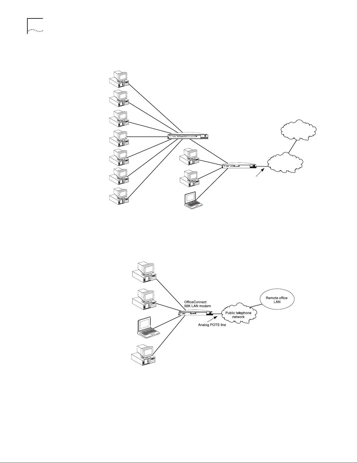
Local Networking with
Access to the Internet
Users can share access to the Internet while continuing to network locally, as
shown in Figure 1.
PWR COLLPKT COAX1234
Alert
OfficeConnect
Hub 8 TPO
Port Status
5678
green = link OK, off = link fail, yellow = partition
Network Utilization
1%2% 3% 6% 12%25% 50%80%
3 Com
Office
¨
Connect
Hub
OfficeConnect
56K LAN modem
LAN STATUS
PWR
CD
Coll
AA
Tx
RD
OH
SD
Alert
OfficeConnect™
1
2 3 4
ISDN LAN Modem
3 Com
Analog POTS line
Internet/Intranet
online service
Public telephone
network
or
Local Networking with
Access to a Remote
Office
Figure 1 Local Networking with Internet Access
Users can share access to a remote office LAN while continuing to network locally,
as shown in Figure 2.
OfficeConnect™
56K LAN Modem
Figure 2 Local Networking with Access to a Remote Office LAN
Page 15

Features Ease of Installation and Use
■ Web-based, point-and-click user interface for easy configuration
■ Automatic Internet configuration verification via your Internet Service Provider
(ISP)
■ Web-based, context-sensitive online help
High Performance
■ Internal 56K modem, capable of transmitting at speeds up to 33.6 Kbps and
downloading at speeds up to 56 Kbps
■ V.42/MNP 2-4 error control and V.42 bis/MNP 5 data compression
■ Hi/fn™ LZS
Compression Control Protocol (RFC 1962) and PPP Stacker LZS Compression
Protocol (RFC 1974)
Connectivity
■ One 56K integrated analog modem
■ Built in four-port 10BASE-T, 10 Mbps Ethernet hub. Up to 25 users can be
supported by connecting to an external eight port-hub
®
compression, which conforms to the following IETF RFCs: The PPP
1
(without compression)
Features 15
■ One pass through analog voice port for connecting an external analog device
Routing
■ IP Routing
■ Dynamic or static IP addresses supplied by your service provider (WAN side)
■ Dynamic Host Configuration Protocol (DHCP) server functionality on the LAN,
which automatically assigns an IP address to a newly-attached PC on the IP
network
■ Domain Name Service (DNS) server functionality for the LAN, which translates
the common, alphanumeric name of a device (for example,
“www.3com.com”) to its numeric IP address
■ Network Address Translation (NAT) between LAN and WAN, which allows
multiple users on the LAN to share a single remote connection
■ Multiplexing traffic from several computers to the same remote destination
■ LAN access to the Internet using a single-user account
Bandwidth Management
■ Dial on Demand (Automatic call connection)
■ Automatic disconnection of idle calls after a user-specified length of time
■ Manual call connection and disconnection
Remote Management
■ Remote management via Web browser-based interface
■ Remote firmware upgrades
1.Current FCC rules limit download speeds to 53Kbps.
Page 16

16 CHAPTER 1: INTRODUCTION
Protocols
■ IETF PPP (RFC 1661, 1662, 1663)
■ IETF Password Authentication Protocol (PAP) and Challenge Handshake
Authentication Protocol (CHAP) security (RFC 1994)
■ MS-CHAP support (as defined in Network Working Group Information Memo:
Microsoft PPP CHAP Extensions. S. Cob, Rev. 1.3 March 1997 including only
the functionality that keeps with IETF 1994).
■ IP address negotiation using IPCP (RFC 1332)
■ Network Address Translation (NAT) between LAN and WAN (RFC 1631)
■ Point-to-Point Tunneling Protocol (PPTP)
Error Control and Data Compression
■ ITU-T V.42
■ ITU-T V.42bis
■ MNP 2-5
Modulation Schemes
■ V.90
■ Backwards compatible with all US Robotics 56K Standards
■ ITU-T V.34+
■ ITU-T V.34
■ ITU-T V.32bis
■ ITU-T V.32
■ ITU-T V.22bis
■ ITU-T V.22
■ ITU-T V.23
■ Bell 212A
■ ITU-T V.21
■ Bell 103
Security
■ PAP CHAP and MS-CHAP support
Upgradability
■ Flash memory for field firmware updates
■ Firmware posted on 3Com’s Web site
■ Fully upgradable to future 56K standards
Diagnostics
■ LED status display
■ Statistics display
Page 17

Features 17
Warranty
■ 3Com Corporation Limited Warranty (refer to the end of this User Guide for
details)
Support for Internet Applications
Your 56K LAN Modem supports applications that use the User Datagram Protocol
(UDP) and the Transmission Control Protocol (TCP). This protocol is used primarily
by Internet games.
Look for the latest list of Internet applications and games that interoperate with
the LAN Modem at
http://www.remoteaccess.3com.com/support/docs/lanmodem/
welcome.html
Page 18

18 CHAPTER 1: INTRODUCTION
Page 19

56K LAN MODEM
2
Connection Types This section discusses LAN side and WAN side connections.
56K Technology Your 56K LAN Modem utilizes the V.90 56K ITU standard, which is backward
F
UNCTIONALITY DESCRIPTION
This chapter provides a description of the 56K LAN Modem’s key functionality,
covering the following topics.
■ Connection Types
■ Call Routing Protocol and IP Address Translation
■ Understanding PPTP
compatible with all US Robotics 56K standards, and is capable of download
speeds of up to 56K
configuration found when an analog modem dials into a digitally connected
Internet Service Provider. Because it requires no analog-to-digital conversions in
the downstream path (which can cause line noise), V.90 can use nearly all of the
available 64K network bandwidth. (Upstream data, typically less speed sensitive,
travels at the standard V.34 rate.)
1
. V.90 technology takes advantage of the typical network
Further information is available in Appendix A of this User Guide, or visit the 56K
web site at
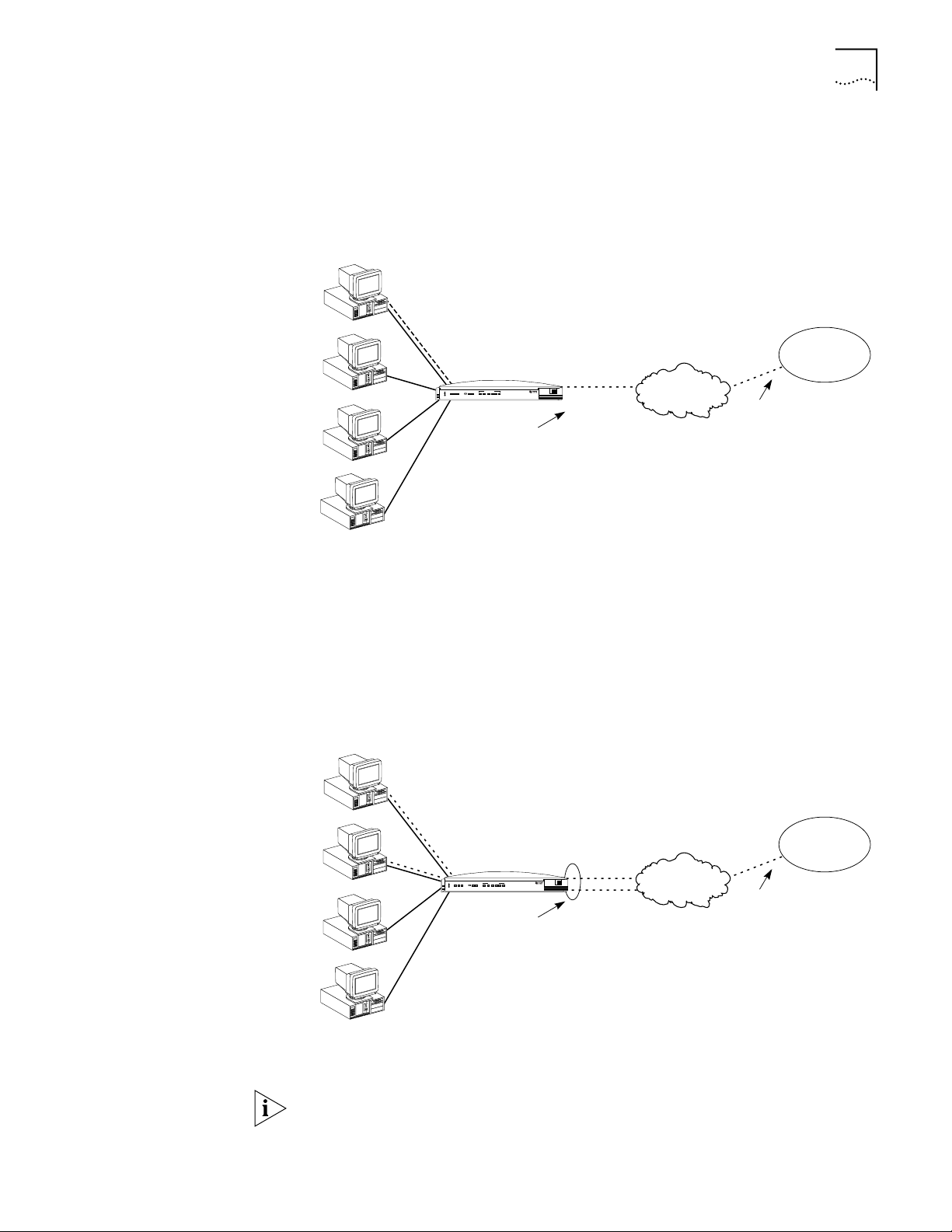
LAN Side Connection On the LAN side, up to four users can connect to the 56K LAN Modem’s built in
Ethernet hub, or up to 25 users may connect to the 56K LAN Modem via an
external user-supplied hub, enabling users to share files and printers and to use
Internet email. An example of ten workstation connections is shown in Figure 3.
1.Capable of receiving at up to 56 Kbps and sending at up to 33.6 Kbps. Due to FCC regulations, receiving speeds limited to 53 Kbps. Actual speeds may vary. Requires compatible phone line and server
equipment. The 56K LAN Modem complies with the V.90 ITU standard and is backwards compatible
with all US Robotics 56K standards. Standard officially determined in February, 1998; ratification expected in September, 1998.
http://www.3com.com/56k.
Page 20

20 CHAPTER 2: 56K LAN MODEM FUNCTIONALITY DESCRIPTION
10 Mbps
Ethernet LAN
OfficeConnect
Hub 8 TPO
Port Status
PWR COLLPKT COAX1234
5678
Alert
green = link OK, off = link fail, yellow = partition
Network Utilization
1%2% 3% 6% 12%25% 50%80%
3 Com
Office
¨
Connect
Hub
LAN STATUS
Coll
Tx
AA
PWR
Alert
SD
CD
OH
RD
OfficeConnect
56KLAN Modem
3 Com
OfficeConnect®
1
2 3 4
56K LAN Modem
Figure 3 56K LAN Modem Ten Workstation Connection Example
An example of the minimum number of connections is shown in Figure 4.
3C886
56K LAN Modem
Figure 4 56K LAN Modem Minimum Connection Example
Application Sharing over the LAN
Most operating systems such as Windows 95, 98 and MacOS provide the
capability for LAN users to share applications, files and printers between
computers. For example, if only one computer has a Web browser, other LAN
users may share the browser for accessing the Internet. Note that speed will likely
be reduced when sharing applications. Refer to your operating system
documentation for instructions on setting up sharing between users on a LAN.
Page 21
Connection Types 21
OfficeConnect
¤
56K LAN Modem
Public telephone
network
Remote office
LAN
Analog connection
3 Com
Oscar’s
Analog connection
Oscar’s PC
Felix’s PC
Murray’s PC
Myrna’s PC
connection
3C886
56K LAN Modem
PWRAA RD SD
Alert
Tx Coll 1 2 3 4 CD OH
LAN STATUS
OfficeConnect
¤
56K LAN Modem
Public telephone
network
Remote office
LAN
Shared analog connection
Mike
Single analog connection
Mike’s PC
Gloria’s PC
Edith’s PC
Archie’s PC
Gloria
3 Com
3C886
56K LAN Modem
PWRAA RD SD
Alert
Tx Coll 1 2 3 4 CD OH
LAN STATUS
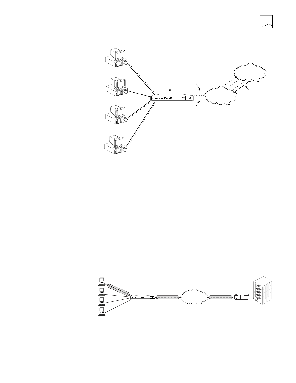
WAN Connection The 56K LAN Modem allows up to 25 users to connect to a WAN using one
analog connection to a single location.
One High Speed
Connection
The WAN connection may be utilized by a single user to connect to a remote site
such as a corporate LAN, as shown in Figure 5.
Figure 5 Single User Connecting to a Remote Site
Sharing the Connection Once the call is established, up to four users may share the single connection
created by the call over the LAN Modem’s four-port built in hub. Or, up to 25 users
may share this connection over an external hub. Figure 6 shows two users on the
LAN accessing the Internet through the same Internet provider and over the same
connection. If you desire, you may also restrict access to certain users. Note that
speed may be affected with multiple users downloading simultaneously.
Figure 6 Shared Connection to a Remote Site
Your 56K LAN Modem is capable of supporting WAN access for up to 25 users.
However, for improved performance it is recommended that no more than four
users attempt to share a single connection at one time.
Page 22

22 CHAPTER 2: 56K LAN MODEM FUNCTIONALITY DESCRIPTION
Call Routing Protocol and IP Address Translation
Placing a Call to a
Previously Defined
Destination
This section describes the call routing protocol used by the 56K LAN Modem and
explains how IP addresses are translated.
The 56K LAN Modem distinguishes between three types of destinations:
■ A direct connection to an Internet Service Provider
■ A direct connection to a Remote Office LAN
■ A direct connection to a Remote Office LAN with Internet Access
If all of these connection types are configured on the 56K LAN Modem and are
associated with your computer, the following algorithm is performed for each of
the following scenarios.
Call Routing While No Other Calls are Connected
If the 56K LAN Modem has not established any calls to a remote destination and
you want to access the Internet from your computer, you simply launch your Web
browser (or whichever networking application you like). When the 56K LAN
Modem receives the information packet requesting access to the WAN, it must
determine which connection type to use. The LAN Modem looks at the destination
Network ID (destination IP address and subnet mask) associated with the packet. If
the Network ID of the packet matches the Network ID of the Remote Office LAN,
with or without Internet access, then the call is placed to the remote LAN. If it
does not match the Network ID of the remote LAN, with or without Internet
access, then the call is routed to the direct ISP connection.
Once the connection is established, any authorized user on the LAN can use this
connection. The 56K LAN Modem will translate each individual user’s local IP
address into a single, shared IP address (assigned by the r emote location), allowing
shared access to the remote location. The following example shows three users
sharing a connection to the Internet and depicts the IP address translation as it
occurs in the LAN Modem.
Page 23
Understanding VPNs and PPTP 23
From the Edge to the Heart
of the Network.
3
C
o
m
POWER
ISDN
Alert
B1
B2 TX COLL 1 2 3 4
3 Com
LAN STATUS
ISDN LAN Modem
3C892
OK
Internet Service
Provider
LAN Modem
Tunnel
terminator
Corporate
network
Understanding VPNs and PPTP
Jack’s PC
192.168.1.2
Chrissy’s PC
192.168.1.3
Larry’s PC
192.168.1.4
Janet’s PC
192.168.1.5
192.168.1.2
192.168.1.4
192.168.1.5
Translates PC IP
addresses to IP
address assigned
by ISP
LAN STATUS
PWRAA RD SD
Tx Coll 1 2 3 4 CD OH
Alert
OfficeConnect 56K LAN Modem
192.168.1.1
3C886
56K LAN Modem
IP address
assigned by ISP
198.6.1.1
3 Com
Analog POTS line
198.6.1.1
198.6.1.1
Public telephone
network
Internet/Intranet or
online service
198.6.1.1
Analog POTS line
Figure 7 IP Address Translation
Virtual private networks (VPN) are private, secure networks created in public
networks such as the Internet. A VPN is essentially a secure, private tunnel within
the Internet. Since VPN calls are placed through a local ISP, they eliminate long
distance charges that would occur from directly dialing to a remote private
network.
One of the protocols which enables a VPN to be created is PPTP. The PPTP protocol
allows for multiple workstations to establish a secure multi-protocol connection to
a remote, private network via a single, locally-dialed ISP account as shown in
Figure 8. Any networking protocols such as IP, IPX and NetBEUI can be supported
transparently through the tunnel. While the LAN Modem supports PPTP, it does
not play an active role in creating or terminating a tunnel.
Figure 8 Connection to an Remote Private Network via an ISP
Page 24

24 CHAPTER 2: 56K LAN MODEM FUNCTIONALITY DESCRIPTION
The main steps for creating a VPN are as follows. Each step is explained in detail in
subsequent sections.
■ Set up the server side of the tunnel connection
■ Set up the client side of the tunnel connection
■ Initiate a tunnel between client and server using your client software
Setting Up the Server
Side of the Tunnel
Setting Up the Client
Side of the Tunnel
In order to establish a tunnel, the client side must be able to dial into a PPTP tunnel
server on the remote private network such as a Windows NT server version 4.0 or
later. If you use Windows NT 4.0, then Service Pack 3 or greater and RAS must be
installed. Also, the protocols required for the private network must be installed on
the PPTP tunnel server. It is recommended that an experienced network
administrator set up the server side. Note that protocols required for the private
network must be installed on each PPTP tunnel client as well as the PPTP tunnel
server.
In order to establish a tunnel, the client side must have PPTP tunnel client software
such as 3Com’s NETBuilder, PathBuilder, Total Control Hub. An additional
requirement is Microsoft’s Windows Dial-Up Networking version 1.2 or higher
which includes the required software VPN adapter, or Windows NT operating
system with Service Pack 3, or Network TeleSystem’s TunnelBuilder™ VPN
software for Windows 3.11 and Macintosh operating systems. This software
should reside on all workstations that wish to create a tunnel to the tunnel server.
Follow instructions provided for installation and set up.
For Windows Dial-Up Networking Users
If you are using Windows Dial-Up Networking version 1.2 or higher, the basic set
up steps are as follows. (Refer to Windows user documentation for details.)
■ Install the PPTP protocol
Establishing a Tunnel via
the LAN Modem
■ Create a RAS phone book entry for the VPN
A RAS phone book entry is similar to other phone book entries with the
exception of an IP address in the Phone number field. Once the Phone book
entry is complete, you can double-click the icon to dial into a server that
supports PPTP via any ISP.
Note that protocols required for the private network must be installed on each
PPTP tunnel client as well as PPTP tunnel server.
As with PPP, no configuration is required on the LAN Modem to use PPTP.
However, you must have an ISP configured on the LAN Modem.
Once the client side and server side are configured, you are ready to create a
tunnel. The steps required for creating a tunnel vary depending on which client
software you are using. Refer to the user documentation provided with your PPTP
software to determine how to establish a tunnel. For instance, if you are using
Windows Dial-Up Networking version 1.2 or higher, double-click the phone book
entry for the VPN.
Once you attempt to create a tunnel, the LAN Modem detects this attempt and
automatically places a call to your ISP. Once the call is connected, a tunnel is
established between your workstation and the tunnel server.
Page 25

Understanding VPNs and PPTP 25
You are ready to access a remote private network LAN as if you were connected
locally. Each workstation that wishes to have access to the remote private LAN will
need to create its own tunnel.
Refer to
http://www.remoteaccess.3com.com/support/docs/lanmodem for more
information. For specific instructions on how to configure a VPN adapter in
Windows 98, 95 or Windows NT, refer to Microsoft’s Web site at
http://www.microsoft.com. and then enter PPTP in the search field.
Page 26

26 CHAPTER 2: 56K LAN MODEM FUNCTIONALITY DESCRIPTION
Page 27

HARDWARE DESCRIPTION AND
3
I
NSTALLATION
This chapter provides an overview of the hardware description and installation of
the 56K LAN Modem.
Package Contents The 56K LAN Modem package contents includes one of each:
■ OfficeConnect 56K LAN Modem
■ Power cable with an AC wall transformer
■ Analog telephone cable
■ 10BASE-T Ethernet cable
■ 3Com Companion Programs CD-ROM
■ OfficeConnect 56K LAN Modem Getting Started Guide
■ Rubber feet and stacking clips
Before You Install the 56K LAN Modem
To install, configure and use the 56K LAN Modem successfully, you must have the
following:
■ An available analog POTS (Plain Old Telephone Service) connection with an
available RJ-11 outlet.
■ A personal computer with TCP/IP and Ethernet connectivity that meets UL
standards in the United States or is certified to CSA standards in Canada.
■ For a PC, a 386 or higher processor is recommended and a 10BASE-T
Ethernet card is required.
■ For an Apple Macintosh computer , system 7.6 or later operating system and
Open Transport (included in System 7.6 or later). Built-in Ethernet
connectivity is provided through an Apple Ethernet port in all Power
Macintosh computers.
■ A frames-capable, JavaScript-enabled Web browser. A Web browser is required to
access and configure your LAN Modem and to view the OfficeConnect 56K LAN
Modem User Guide. You may use the customized browser provided on the 3Com
Companion Programs CD-ROM, or you may use any frames-capable Web browser,
such as Netscape Navigator (3.0 and later) or Microsoft Internet Explorer (3.0 and
later).
If you already have a version of Microsoft’s Internet Explorer W eb browser installed
and would like to install a later version, you should first uninstall the older version.
During installation, you may be asked to replace the older files. It is recommended
that you do so.
Page 28

28 CHAPTER 3: HARDWARE DESCRIPTION AND INSTALLATION
■ TCP/IP software. TCP/IP is provided as part of the Windows 98, 95, NT and
Macintosh System 7.6 and later operating systems. For Windows 3.11 users,
TCP/IP software is provided on the 3Com Companion Programs CD-ROM.
Available storage space on your computer’s hard drive is not required because
nothing is installed onto your computer as part of the 56K LAN Modem setup
procedure. If you would like to copy any programs or documents from the
included CD-ROMs, ensure that you have available hard disk space.
Front Panel LED Description
The front panel provides the following LEDs.
LAN STATUS
PWR CDAA OH
Alert
RD SD TX COLL 1 2 3 4
Figure 9 56K LAN Modem Front Panel
56K LAN Modem
3C886
3 Com
The functions of the front panel LEDs are described in Table 4. These front panel
LEDs indicate proper operation and display 10BASE-T and analog port activity
status.
Table 4 Front Panel LED Indicator Definitions
LED Color Description
Alert Amber Operational Status. Lit during power-on self-diagnostic test or
PWR Green Power Indicator. Remains lit as long as power is supplied to the
AA Green Auto Answer. Indicates the 56K LAN Modem’s answer mode.
CD Green Carrier Detect. Remains lit if the 56K LAN Modem receives a valid
RD Green Received Data. Flashes when the LAN Modem receives data from
SD Green Send Data. Flashes when the LAN Modem sends data to a remote
OH Green Off Hook. Remains lit when the modem has gone off hook.
TX Green Ethernet Transmit Status. Flashes green when data is being
after pressing the reset button.
Off indicates the unit has passed the diagnostic test and is working
properly.
Flashes if one or more of the diagnostics have failed or after the
unit is placed in firmware download mode and is awaiting
firmware upgrade.
unit.
Flashes during an incoming call.
Remains lit for the duration of the call.
Off when the LAN Modem originates a call.
data signal (carrier) from a remote modem (such as an ISP),
indicating that data transmission is possible.
a remote site.
site.
transmitted to the Ethernet LAN from the 56K LAN Modem .
Off indicates that no data is being transmitted to the Ethernet LAN
from the 56K LAN Modem.
Page 29
Installing the 56K LAN Modem 29
Table 4 Front Panel LED Indicator Definitions (continued)
LED Color Description
Coll Amber Ethernet Collision Status. Flashes amber when some collisions
are taking place on the Ethernet LAN.
Off indicates that no collisions are taking place on the Ethernet
LAN.
Ports 1-4 Green Ethernet LAN Port Status. On indicates that the unit detects the
Ethernet link integrity signal from an attached computer and
operation is normal.
Flashes when the LAN Modem receives data on the associated
port.
Off indicates the unit does not detect the Ethernet link integrity
signal. The Ethernet cable may not be properly connected or the
cable may be the wrong polarity.
Back Panel Connector
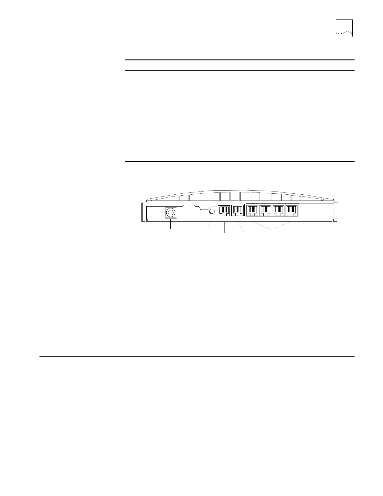
Description
The back panel provides the following components.
10-18 VDC
0.8 A MAX
Power
Connector
Figure 10 56K LAN Modem Back Panel
RESET
LINE PHONE
Reset Button
Telephone
Line
4
Analog
Device
Four Ethernet
10BASE-T Connectors
312
LAN
From left to right the back panel consists of the following.
■ Power: Connect the power module cable to this port.
■ Reset: Press this button to re-initialize the unit.
■ Line: Connect the provided RJ-11 analog line from the wall outlet to this port.
■ Phone: Connect an external analog device, such as a telephone or fax
machine, to this port.
■ Four 10BASE-T Ethernet Ports: Connect the computers on your LAN, or an
external hub, to these ports.
Installing the 56K LAN Modem
Before You Begin Before you begin, you will need the following in addition to the 56K LAN Modem:
This section describes how to do the following.
■ Install the analog cable
■ Connect to a 10BASE-T Ethernet LAN
■ Install analog equipment
■ Install the power cable
■ RJ-11 (6-pin) to RJ-11 (6-pin) telephone cable which was provided in your
modem package.
Page 30

30 CHAPTER 3: HARDWARE DESCRIPTION AND INSTALLATION
■ 10BASE-T Ethernet cable (8-pin to 8-pin connectors) labeled Ethernet which
was provided in the package. It is recommended that you use the cable
provided. However, if you choose to use another cable it must be a
straight-through 10BASE-T Ethernet cable. A crossover cable may not be used
to connect the LAN Modem to a workstation.
■ Power adapter (you must use the power adapter provided in the package).
Installing the Analog
Cable
Connecting to a
10BASE-T Ethernet Port
To install the analog cable:
1 Connect one end of the RJ-11 analog cable to the RJ-11 analog port labeled Line
on the 56K LAN Modem’s back panel, as shown in Figure 11.
LINE PHONE
RESET
10-18 VDC
0.8 A MAX
Figure 11 Analog Cable Connection
2 Connect the other end of the RJ-11 analog cable to a POTS analog wall jack.
To connect a computer to the 56K LAN Modem, do the following.
1 Insert one end of the 10BASE-T Ethernet cable into one of the four LAN ports on
the back of the 56K LAN Modem, as shown in Figure 12.
LINE PHONE
RESET
10-18 VDC
0.8 A MAX
Figure 12 10BASE-T Ethernet LAN Connection
2 Insert the opposite end of the cable into your computer’s 10BASE-T Ethernet port.
CAUTION: Connect only one computer to the 56K LAN Modem for initial
configuration. Once configuration is complete, you may connect the rest of the
computers to the LAN.
Page 31

Installing the 56K LAN Modem 31
Connecting to Another
Ethernet Hub
You can connect to another Ethernet hub to allow up to 25 users to access the
WAN. Instructions for adding another Ethernet hub to allow 10 users, a more
common scenario, is as follows.
Before You Begin
In addition to an external 10BASE-T Ethernet hub, you will need a 10BASE-T
Ethernet cable, which may have been provided with the additional hub. If the hub
to which you are connecting your LAN Modem does not have an MDI/X switch,
you must use a crossover cable.
1 Insert one end of the 10BASE-T Ethernet cable into one of the four LAN ports on
the back of the LAN Modem, as shown in Figure 13.
PHONE
10-18 VDC
0.8A MAX
10-18 VDC
0.8A MAX
+
-
+
-
LINE
RESET
87654321
MDI/MDIX
Figure 13 10BASE-T Hub-to-Hub Connection
2 Insert the opposite end of the cable into a 10 BASE-T Ethernet port on the other
Ethernet hub.
If you are connecting to an OfficeConnect Hub 8/TPO, insert the opposite end of
the Ethernet cable into port 8 and then set the MDI/X switch to MDI (that is,
pressed in). Make sure that the LED associated with that Ethernet port is lit. If it is
not, try changing the MDI/X switch setting.
Page 32

32 CHAPTER 3: HARDWARE DESCRIPTION AND INSTALLATION
Installing Analog
Equipment
You can connect an analog touch-tone telephone, answering machine, fax
machine, or external analog modem to the 56K LAN Modem’s pass-through
Phone port.
You will need an RJ-11 to RJ-11 cable that came with the analog device for your
analog phone port connection.
To install an analog device:
1 Insert one end of an RJ-11 cable into the port labeled Phone on the back of the
56K LAN Modem, as shown in Figure 14.
LINE PHONE
RESET
10-18 VDC
0.8 A MAX
Installing the Power Cable
Figure 14 Analog Equipment Connection
2 Insert the other end of the RJ-11 cable into the appropriate RJ-11 port on the
analog device.
To install the power cable:
1 Connect the 56K LAN Modem power module cable to the 10-18 VDC power
connector on the back panel of the 56K LAN Modem, as shown in Figure 15.
TELCO PHONE
RESET
10-18 VDC
0.8 A MAX
Figure 15 Power Cable Connection
Page 33

Installing the Power Cable 33
2 Plug the other end of the power module into a surge-protected standard 110 VAC
wall outlet.
The PWR and AA indicator LEDs illuminate. The ALERT LED flashes momentarily as
the unit undergoes a power-up self-test diagnostic. Once completed, only the
PWR LED and LAN port LED remain lit.
This completes the 56K LAN Modem installation.
If you do not have TCP/IP installed and set up on your computer, refer to
Chapter 4, “Setting Up TCP/IP for Windows and Macintosh.” If you already have
TCP/IP installed and set up on your computer , r efer to Chapter 5, “Configuring the
56K LAN Modem.”
Page 34

34 CHAPTER 3: HARDWARE DESCRIPTION AND INSTALLATION
Page 35

SETTING UP TCP/IP FOR WINDOWS
4
TCP/IP Setup Using Windows 95 and 98
AND MACINTOSH
This chapter describes how to set up the Windows and Macintosh operating
system (OS) TCP/IP stack. Your computer must have a TCP/IP stack in order to use
the 56K LAN Modem. If you already have TCP/IP installed and set up on your
computer, then go on to Chapter 5. These instructions vary depending upon your
particular operating system. Refer to the appropriate section.
■ TCP/IP Setup Using Windows 95 and 98
■ TCP/IP Setup Using Windows NT 4.0
■ TCP/IP Setup Using Mac OS 7.6 or later
■ TCP/IP Setup Using Windows 3.11
Both Windows 95 and 98 provide TCP/IP as part of its standard operating system.
To set up TCP/IP for the 56K LAN Modem, do the following.
You may be prompted for your Windows 95 or 98 installation disks or CD-ROM.
1 From the Control Panel, double click Network.
The Network dialog box appears.
Figure 16 Network Dialog Box
2 Click Add.
The Select Network Component Type dialog box appears.
Page 36

36 CHAPTER 4: SETTING UP TCP/IP FOR WINDOWS AND MACINTOSH
Figure 17 Select Network Component Type Dialog Box
3 Select Protocol and then click Add.
The Select Network Protocol dialog box appears.
Figure 18 Select Network Protocol Dialog Box
4 From the Manufacturers list box, select Microsoft, and then from the Network
Protocols list box, select TCP/IP.
5 Click OK.
6 From the Network Configuration list box, select TCP/IP and then click Properties.
Page 37

TCP/IP Setup Using Windows 95 and 98 37
Figure 19 Network Dialog Box
7 Select IP Address.
The IP Address dialog box appears.
Figure 20 IP Address Dialog Box
8 Most users should select Obtain an IP Address automatically as most LANs utilize
dynamic IP addresses. If this LAN uses static IP addressing, enter the IP address and
subnet mask. (You can obtain this information from your system administrator or
ISP.)
9 Select the Advanced tab.
The TCP/IP Properties Advanced screen opens.
Page 38

38 CHAPTER 4: SETTING UP TCP/IP FOR WINDOWS AND MACINTOSH
Figure 21 TCP/IP Properties Advanced Screen
10 Check the box to set TCP/IP as the default protocol.
TCP/IP Setup Using Windows NT 4.0
11 Click OK to close the TCP/IP Properties dialog box.
12 Click OK to close the Network dialog box.
13 Restart Windows 98 or 95 to let these changes take effect.
Windows NT 4.0 provides TCP/IP as part of its standard operating system. If you
have not already set up TCP/IP, do the following.
You will need your Windows NT 4.0 installation CD-ROM.
1 From the Control Panel, double click Network.
The Network dialog box appears.
2 Select the Protocols tab, as shown in Figure 22.
Page 39

TCP/IP Setup Using Windows NT 4.0 39
Figure 22 Windows NT Protocols Configuration Window
3 Click Add.
The Select Network Protocol window appears as shown in Figure 23.
Figure 23 Select Network Protocol Window
4 Select TCP/IP Protocol and then click OK.
The following message appears.
Figure 24 DHCP Message Box
5 Select the appropriate response for your network.
Page 40

40 CHAPTER 4: SETTING UP TCP/IP FOR WINDOWS AND MACINTOSH
If you are using dynamic IP addressing on your LAN and would like your LAN
Modem to act as your DHCP server, select Yes. Note that you must select Yes if
there is no other DHCP server on your LAN.
6 You ar e then prompted to insert your installation CD-ROM. Insert the Windows NT
4.0 CD ROM and then click Continue.
If you have Remote Access Service (RAS) installed on your PC after the appropriate
files are copied to your PC, a message box asks whether or not you would like
TCP/IP installed for RAS. If you select Yes, you must select the device you want to
access remotely and then click Close.
7 After the appropriate files are copied to your PC, you will see TCP/IP Protocol listed
in the Network Protocols group box, as shown in Figure 25.
Figure 25 Network Protocols Window
8 Click Close.
The Microsoft TCP/IP Properties window appears, as shown in Figure 26.
Page 41

TCP/IP Setup Using Mac OS 7.6 or later 41
Figure 26 Microsoft TCP/IP Properties Window
9 From the Adapter drop down list box, select the Ethernet card that is connected to
the 56K LAN Modem.
TCP/IP Setup Using Mac OS 7.6 or later
10 If this LAN uses dynamic IP addresses, select Obtain an IP Address automatically. If
this LAN uses static IP addresses, enter the IP address and subnet mask.
11 Click OK.
12 Click Yes to restart your PC and allow the changes to take effect.
If you are using Macintosh operating system version 7.6 or later, Open Transport
(OT) is provided and installed by default. If you did not install OT when first
installing your system software, perform a custom installation of your system
software to add OT version 1.1 or later.
To set up TCP/IP for Mac, do the following.
1 From the Apple menu, select Control Panels and then select TCP/IP.
The TCP/IP dialog box appears.
Page 42

42 CHAPTER 4: SETTING UP TCP/IP FOR WINDOWS AND MACINTOSH
Figure 27 TCP/IP Dialog Box for Macintosh Computers
2 Select Ethernet from the Connect via drop down list box.
3 Most users should select Using DHCP Server from the Configure drop-down list
box, as most LANs utilize dynamic IP addressing. If this LAN uses static IP
addressing, select Manually and then enter the IP address.
TCP/IP Setup Using Windows 3.11
Setting up TCP/IP using
MS_TCP
If you are using Windows 3.11, a TCP/IP stack may not be provided as part of the
operating system. If you do not have a TCP/IP stack, you can use MS_TCP which is
provided on the 3Com Companion Programs CD-ROM.
To set up MS_TCP, do the following.
1 Install MS_TCP, located on the 3Com Companion Programs CD-ROM, onto your
hard drive.
2 From the Program manager, click Network.
Figure 28 Program Manager Group Box
3 From the Network group box, click Network Setup.
Page 43

TCP/IP Setup Using Windows 3.11 43
Figure 29 Network Group Box
4 From the Network Setup dialog box, click the Drivers button.
Figure 30 Network Setup Dialog Box
5 From the Network Drivers dialog box, click Add Protocol.
6 Select Unlisted or Update Protocol and then click OK.
7 From the Install Driver dialog box, enter the path to the MS _TCP directory.
For example, if you installed MS_TCP on your C: drive in a directory called
MS_TCP, you would enter C:\MS_TCP.
8 Select MS TCP/IP-32.X and then click OK to install.
9 After the installation is complete, click Close.
10 Click OK.
11 From the MS TCP/IP Configuration dialog box, check the Auto Configuration
check box and then click OK.
12 Restart your PC to allow the changes to take effect.
Page 44

44 CHAPTER 4: SETTING UP TCP/IP FOR WINDOWS AND MACINTOSH
Page 45

CONFIGURING THE 56K LAN MODEM
5
This chapter describes the typical configuration procedure for your 56K LAN
Modem. These steps include setting up your 56K LAN Modem and connecting to
the Internet. If you have already followed the instructions provided in your Getting
Started Guide, then you have already set up the typical configuration. Go to
Chapter 6, “Advanced Configuration” to learn about additional configuration
changes you might like to make.
The configuration windows shown in this chapter may differ slightly from what is
displayed on your computer.
Typical Configuration The typical configuration covers the following main steps.
Launch
Web Browser
Run
ISP Wizard
Verify
Configuration
Figure 31 Main Steps for Typical Configuration
Before You Begin Before you configure the 56K LAN Modem, you should have already completed
the following:
■ Installed the hardware as described in Chapter 3, “Hardware Description and
Installation”
■ Installed and set up TCP/IP on all the computers you intend to connect to the
LAN Modem. If TCP/IP is not installed and set up, refer to Chapter 4.
CAUTION: You should only have one computer physically connected to the 56K
LAN Modem during configuration. Once you complete the initial configuration
process, connect any additional computers you would like to have on the LAN.
Page 46

46 CHAPTER 5: CONFIGURING THE 56K LAN MODEM
You Should Have This
Information
Determine Whether You
Use Dynamic or Static IP
Addresses
If you want to set up a connection to an ISP, you will need:
■ Your ISP’s telephone access number.
■ Your user name, password and DNS address (if your service provider requires a
specific DNS address).
Your setup procedure varies depending upon whether you are using a dynamic or
a static IP address.
A static IP address is a permanent, manually-assigned address recognized by a
remote server, such as a corporate LAN or an ISP. By default, your 56K LAN
Modem dynamically assigns an IP address to each computer.
If you have been
accessing a remote server via a static IP address prior to installing your 56K LAN
Modem, you may be required to perform additional configuration steps. The first step
is to determine your static versus dynamic IP addressing scenario.
If you determine that your computer has a static IP address, refer to “Setting Up
Y our Computer If You Have a Static IP Address.” If your computer has a dynamic IP
address, you may begin configuring the 56K LAN Modem directly. Refer to
“Configuring the 56K LAN Modem for the Typical Configuration”.
Determine your IP address type as follows:
■ For Windows 95, 98 and NT 4.0 Users: From the Start menu, select Settings
and then Control Panel. Double-click Network. Select TCP/IP for the Ethernet
card associated with your 56K LAN Modem and then click Properties. Select
the IP Address tab.
If the radio button labeled Obtain an IP address automatically (Windows 95
and 98) or Obtain an IP address from a DHCP server (Windows NT 4.0) is
selected, then your computer has a dynamically assigned IP address. You are
ready to continue directly with “Configuring the 56K LAN Modem for the
Typical Configuration”.
If the radio button labeled Specify an IP address is selected, your computer has
a static IP address.
■ For Mac Users: From the Apple menu, select Control Panels, and double-click
TCP/IP. Choose Ethernet from the Connect Via pop-up menu, if it is not already
chosen.
If the Configure pop-up menu is set to Using DHCP Server , then your computer
has a dynamically assigned IP address. You are ready to continue directly with
“Configuring the 56K LAN Modem for the Typical Configuration”.
If Configure is not set to Using DHCP Server, and you have specific values listed
in any of the following fields: IP address, Subnet mask, Router address, or
Name server address, then your computer has a static IP address.
■ For Windows 3.11 Users: From the Program Manager, double-click the
Network program group icon. Double-click the Network Setup icon. Click the
Drivers button. Highlight the MS TCP/IP - 32.X entry and click Setup. If
Enable
Automatic DHCP Configuration is checked, then your computer has a dynamic IP
address. You are ready to continue directly with “Configuring the 56K LAN
Modem for the Typical Configuration”. If an IP address is entered in the IP
Address box, then your computer has a static IP address.
Page 47

Typical Configuration 47
Setting Up Your
Computer If You Have a
Static IP Address
If your computer has a static IP address, you must verify and possibly change some
settings on your computer before you begin the LAN Modem configuration
procedure. The 56K LAN Modem must be your gateway to get outside of your
LAN as well as one of your DNS servers. Follow the procedure in the appropriate
section to make sure that this is the case. Note that if your computer has a
dynamic IP address, this configuration would occur automatically and you can go
on to “Configuring the 56K LAN Modem for the Typical Configuration”.
These instructions assume that the LAN Modem configuration is set the factory
default. If you are moving the LAN Modem from a different LAN, reset the LAN
Modem before you begin. To do so, refer to Chapter 8, “Resetting the 56K LAN
Modem to a Factory Default Setting”.
For Windows 98 and 95 Users
1 From the Start menu, select Settings and then Control Panel.
2 Double-click Network and then select TCP/IP.
If you have multiple TCP/IP entries, select TCP/IP for the Ethernet card associated
with the 56K LAN Modem.
3 Click Properties and then select the Gateway tab and write down the first IP
address in the Installed Gateways list.
If nothing is entered in the Installed Gateway list, enter an IP address that does not
belong to any workstation on your LAN, but is in the subnet that you have chosen
for your LAN. Write this IP address down for later use.
4 Click on the DNS Configuration tab.
5 In the DNS Server Search Order edit box, enter the Gateway IP address you wrote
down as part of the previous step and then click Add.
6 Click OK to close the TCP/IP Properties box.
7 Click OK to close the Network control panel.
You are asked to restart your computer.
8 Click OK.
For Windows NT 4.0 Users
1 From the Start menu, select Settings and then Control Panel.
2 Double-click Network and then select the Protocols tab.
3 Highlight TCP/IP and then click Properties.
4 Click the IP Address tab and then select the Ethernet card associated with the 56K
LAN Modem from the Adapter drop-down list box.
5 Write down the IP address in the Installed Gateways box.
If nothing is entered in the Installed Gateway list, enter an IP address that does not
belong to any workstation on your LAN, but is in the subnet that you have chosen
for your LAN. Write this IP address down for later use.
6 Click on the DNS tab.
7 Click Add.
Page 48

48 CHAPTER 5: CONFIGURING THE 56K LAN MODEM
8 In the TCP/IP DNS Server box, enter the Gateway IP address you wrote down as
part of the previous step and then click Add.
9 Click OK to close the Microsoft TCP/IP Properties dialog box.
10 Click OK to close the Network Control Panel box.
You are asked to restart your computer.
11 Click OK.
For Macintosh Users
1 From the Apple menu, open Control Panels. Double-click TCP/IP.
2 Choose Ethernet from the Connect Via pop-up menu, if it is not already chosen.
The Configure drop-down list box should be set to Manually if you are on a static
network.
3 Note the series of numbers entered in the Router address box. Write these
numbers down.
4 Enter this series of numbers into the Name Server Address box. (If you already
have existing address(es) listed, add the new address below the last entry.)
5 Choose File and Close.
6 When asked to save your changes, do so by choosing Save.
You may want to rename this configuration so that your previous configuration is
not overwritten.
For Windows 3.11 Users
1 From the Program manager, click Network.
2 From the Network group box, click Network Setup.
3 From the Network Setup dialog box, click the Drivers button.
4 From the Network Drivers dialog box, double-click Microsoft TCP/IP-32.
5 Uncheck Enable Automatic DHCP Configuration.
6 Write down the number in the Default Gateway field.
7 Click OK.
8 Restart your PC to allow the changes to take effect.
Y ou ar e now ready to install your 56K LAN Modem. Refer to “Configuring the 56K
LAN Modem for the Typical Configuration” to continue.
Page 49

Typical Configuration 49
Configuring the 56K LAN
Modem for the Typical
Configuration
The following steps allow you to configure the 56K LAN Modem for the typical
configuration. You may need the IP address which you recorded previously in the
“Setting Up Your Computer If You Have a Static IP Address”section.
1 Launch your Web browser.
The LAN Modem attempts to use its default IP address (192.168.1.1) to
communicate with the attached computer. If communication cannot be
established, the LAN Modem will change its default IP address. If this occurs, the
unit will reset itself and then function as described in this section.
Regardless of the start page to which your Web browser is set, your W eb browser
will go to the 56K LAN Modem configuration setup screen.
A welcome message appears, as shown in Figure 32.
Figure 32 Initial Setup Welcome Window
2 Click Continue.
A message box appears indicating that the LAN Modem clock is being
synchronized to the date and time on your PC.
The Set Password window appears. This password is used to guard access to the
56K LAN Modem’s configuration program. If you would like to restrict access to
the configuration settings, select a password and record it in a safe place.
Page 50

50 CHAPTER 5: CONFIGURING THE 56K LAN MODEM
Figure 33 Set Password Window
3 Enter a password in the Password field and then enter the same password in the
Password (repeat) field to confirm it.
If do not wish to enter a password, leave the fields empty.
4 Click Submit.
A message box indicates that your password has been set. The ISP Wizard
appears.
If you do not want to use the ISP Wizard, click Abort to reach the 56K LAN
Modem main configuration page. Refer to “Setting Up Additional Service
Providers”for instructions on configuring your ISP connection manually. Note that
the ISP Wizard is a helpful step towards confirming the proper operation of your
LAN Modem.
Page 51

Typical Configuration 51
Figure 34 ISP Wizard Window
5 In the ISP Name field, enter a name that you wish to associate with your ISP.
6 In the Dial Out Prefix field, enter the number required to access an outside line. An
example would be dialing “9” for use with a PBX. If not required, leave this field
blank.
7 In the Call Waiting Disable Command field, enter the appropriate command to
disable call waiting. Your telephone company should provide this value.
If you have Call Waiting enabled on your line, and you do not disable Call Waiting,
then any incoming calls will disrupt your modem connection.
8 In the Telephone Number field, enter the telephone number of your ISP.
If you want to enter another telephone number to connect to your ISP, refer to
“Editing Service Provider Profiles” after you have completed this typical installation
procedure.
9 In the User ID and Password fields, enter your user ID and password for your ISP
account.
10 If your ISP requires a DNS address, enter it in the DNS Address field. If you are not
sure, leave this field blank.
11 Click Continue.
A call is launched to your ISP. The TX LED flashes, indicating data transmission
from your 56K LAN Modem across your WAN. A successful connection to the
Internet verifies the successful configuration of your 56K LAN Modem and ISP
connection. A congratulations message appears.
12 Click Continue to exit the ISP Wizard and go directly to the LAN Modem’s World
Wide Web homepage.
Page 52

52 CHAPTER 5: CONFIGURING THE 56K LAN MODEM
If you cannot access a Web site and your computer has a static IP address, refer to
“Configuring a Static IP Address on the 56K LAN Modem”. If you experience any
other problems, refer to Chapter 7, “Placing, Receiving and Disconnecting Calls”.
You will be connected to the LAN Modem Web site. This verifies the correct
configuration of your ISP connection.
From here, you can read any new, up-to-date information, register your product,
or perform firmware upgrades as they become available. If you have installed the
Custom Browser from the 3Com Companion Programs CD-ROM, access this page
at any time by clicking the Updates button from your browser’s Links menu bar.
Otherwise, the latest information can be accessed directly at
http://www.remoteaccess.3com.com/support/docs/lanmodem/
welcome.html
.
This configuration covers the typical parameters needed to connect to your ISP.
There are additional parameters for this ISP connection which have been set to a
typical default. These parameters include Domain Name, Compression, NAT, and
WAN Link IP Address. In addition, you can enter a second telephone for
connection to your ISP. For information on these parameters and instructions for
changing their default values, refer to “Editing Service Provider Profiles.”
Configuring a Static IP
Address on the 56K LAN
Modem
To return to the LAN Modem’s main configuration page, enter the following
address in your Web browser’s address window:
http://lanmodem. Alternatively, if
you are using the Custom Browser, clicking the Configure Modem link takes you
directly to this main page.
The connection established as a result of the ISP Wizard will automatically
disconnect after fifteen minutes of inactivity, by default.
To learn more about your LAN Modem’s main page, or to configure additional
parameters, go on to “56K LAN Modem Main Page”. Otherwise, go on to
Chapter 8, “Troubleshooting and Maintenance”.
If you followed the steps in “Configuring the 56K LAN Modem for the Typical
Configuration” and were not able to connect to a Web site and your computer
has a static IP address, there may be an incompatibility between the IP address on
your computer and the IP address on the 56K LAN Modem. To correct this, do the
following.
1 Enter the following URL in your Web browser: http://lanmodem. Alternatively,
you can enter http://3com.oc.lanmodem.
2 From the 56K LAN Modem’s main configuration page, click the icon representing
the 56K LAN Modem from the center illustration.
The LAN (Ethernet) Parameters page appears.
3 In the IP Address field, enter the default gateway address you recorded as
described in “Setting Up Your Computer If You Have a Static IP Address”.
4 Click Submit.
The 56K LAN Modem resets.
5 Click Refresh from your Web browser’s menu bar.
The Enter Password window appears.
Page 53

Typical Configuration 53
6 Enter your password and then click Submit.
The 56K LAN Modem’s main configuration page appears.
7 Click the ISP Wizard button.
You will see the information you entered previously.
8 Click Continue.
A call is launched to your ISP. A congratulations message appears when you
successfully connect to your ISP.
This configuration covers the typical parameters needed to connect to your ISP.
There are additional parameters for this ISP connection which have been set to a
typical default. These parameters include Domain Name, Compression, NAT, and
WAN Link IP Address. In addition, you can enter a second telephone number for
the connection to your ISP. For information on these parameters and instructions
for changing their default values, refer to “Editing Service Provider Profiles.”
9 Click Continue.
You will be connected to the LAN Modem Web site. This verifies the correct
configuration of your ISP connection.
From here, you can read any new, up-to-date information, register your product,
or perform firmware upgrades as they become available. If you have installed the
Custom Browser from the 3Com Companion Programs CD-ROM, access this page
at any time by clicking the Updates button from your browser’s Links menu bar.
Otherwise, visit the LAN Modem homepage directly at the following URL:
http://www.remoteaccess.3com.com/support/docs/lanmodem/welcom
.
e.html
Configure Additional
Parameters
If you would like to configure another ISP or a connection to a remote office LAN,
access the main configuration page via one of the following methods:
■ If you are using the 56K LAN Modem custom Web browser, click Configure
Modem to modify additional parameters.
■ If you are not using the 56K LAN Modem Web browser, enter the following
URL: http://lanmodem. This will take you to the main configuration page.
Alternatively, you can enter http://3com.oc.lanmodem.
Once you have successfully completed the initial configuration, you may add any
additional computers to your LAN. Refer to Chapter 6, “Advanced Configuration”
for instructions.
Page 54

54 CHAPTER 5: CONFIGURING THE 56K LAN MODEM
56K LAN Modem Main Page
The 56K LAN Modem main page is shown in Figure 35. From here you can access
configuration parameters as well as place and disconnect manual calls.
Bookmark this page for easy access. Alternatively, if you are using the 56K LAN
Modem Web browser, click Configure Modem from the Links menu bar to go
directly to your LAN Modem’s main page.
Links From the
Illustration
Figure 35 56K LAN Modem WebWizard Main Page
The 56K LAN Modem configuration home page, also called the WebWizard,
provides links to configuration, dialing and statistics screens. There are links from
the illustration’s images, from the buttons listed in the left vertical frame as well as
textual links from beneath the center graphic.
By clicking on the icons shown in the illustration you may jump to the following
locations.
■ Service Providers: Jumps to the Service Providers page where you may
configure connections to an ISP or a private network.
■ Workstations: Jumps to the Workstation Selection page where you view the
IP address of your computer as well as change workstation associations with
service providers.
■ LAN Parameters: Jumps to the LAN Parameters page where you may
configure Ethernet parameters for your LAN.
■ Data Call Parameters: Jumps to the data call timeout parameters page. From
here you may set inactivity timers, which allow calls to be disconnected due to
network inactivity, keeping telephone usage and Internet access costs down.
Page 55

56K LAN Modem Main Page 55
■ Current Call Status: Jumps to the call statistics page where the latest call
information is displayed.
Links from the Buttons
■ Home: Jumps to this main configuration page of the 56K LAN Modem.
■ ISP Wizard: Allows you to configure an ISP profile. Note that if you have
already configured an ISP using the ISP Wizard, invoking the ISP Wizard again
will create a new profile and overwrite any previous settings. If you would like
to add a second ISP profile, use the Service Providers icon to access the Service
Providers configuration page.
■ Manual Calling: Jumps to the Manual Calling page where you may manually
place and disconnect calls.
■ Statistics: Jumps to the Statistics page where you may view statistics such as
system, current call, last call and service provider.
■ Maintenance: Jumps to the Maintenance page. Here you can reset the 56K
LAN Modem as well as enter firmware download mode, which allows you to
easily download the latest firmware. You can also set the Auto Answer ring
number from this page.
■ Password: Jumps to the Password page where you may change or set your
password, as well as establish lock configuration over your LAN Modem’s
parameter settings.
Context-sensitive help is available in the bottom frame of each configuration
screen. To increase the size of the help frame, drag the pane separator up.
This chapter covers the typical configuration steps required for a basic
understanding of your 56K LAN Modem functionality. For further configuration
options, refer to Chapter 6, “Advanced Configuration”.
Page 56

56 CHAPTER 5: CONFIGURING THE 56K LAN MODEM
Page 57

6
ADVANCED CONFIGURATION
This chapter describes the advanced configuration steps required for connecting
to private networks such as a remote office LAN, and also provides instructions for
changing your 56K LAN Modem’s default settings. You should have first followed
the typical configuration steps as detailed in the previous chapter before
attempting to configure advanced parameters.
The configuration windows shown in this chapter may differ slightly from what is
displayed on your computer.
Advanced Configuration
Setting Up Additional Service Providers
This section provides instructions for the following.
■ Setting up additional service providers
■ Associating service providers with computers
■ Editing service provider profiles
■ Configuring LAN parameters
■ Configuring modem control parameters
■ Changing data call parameters
■ Changing your password
■ Locking the configuration
■ Disabling password protection for the Manual Calling screen
■ Configuring the LAN Modem from a remote location
A service provider is a location outside of your LAN that you would like to access,
such as an ISP for connecting to the Internet or a private network such as a remote
office LAN. You can define up to four service providers (that is, remote
destinations) on the 56K LAN Modem.
This section describes the following procedures.
■ Setting up a connection to an ISP
■ Setting up a connection to a private network
■ Associating computers on the LAN with selected service providers
■ Editing service provider profiles
If you have set up a connection to an ISP as part of the typical (that is, initial) setup
procedure, then you have already defined one service provider. Because this is
considered a typical configuration, some default values have been assumed. For
example, an ISP connection is associated with all of the computers connected to
Page 58

58 CHAPTER 6: ADVANCED CONFIGURATION
your LAN; in other words, all (up to 25) computers on the LAN have access to and
may connect to that ISP and therefore the Internet. You may wish to review the
profile for this ISP connection to determine if you would like to make any changes.
For instructions, refer to “Editing Service Provider Profiles.”
ISP Versus Private
Network
Setting Up a Connection
to an ISP
There are two types of service providers you may configure on your LAN Modem,
an ISP and a Private Network. A description of each follows.
When to Select ISP
Choose ISP when you wish to set up a direct connection to the public Internet, via
an Internet Service Provider.
When to Select Private Network
Select Private Network when you wish to connect directly to a remote, private LAN
such as a corporate network. For instance, if you want to dial into your main office
from home in order to access the servers at your office for email, printing, etc.,
then select private network as the type of additional service provider to configure.
If the private network provides the option of accessing the Internet through their
connection, and you want to reach the Internet through your corporate LAN (as
opposed to a direct connection to an ISP), then choose that option when
configuring your private network parameters.
This section describes setting up your 56K LAN Modem for Internet access.
Before You Begin
Before you begin, you will need the following information from your ISP:
■ Telephone number(s) you must dial to access this ISP
■ User ID and password
■ DNS IP address(es). This information is required only if your ISP does not
provide an address dynamically.
Page 59

Setting Up Additional Service Providers 59
Setting Up a Connection to the Internet
To set up a connection to an ISP, do the following.
1 From the 56K LAN Modem main page, click the Service Providers image.
Figure 36 ISP Service Provider Selection Window
2 Select New (Internet Service Provider) from the drop down list box and then click
Select.
The Internet Service Provider Parameters window appears.
Page 60

60 CHAPTER 6: ADVANCED CONFIGURATION
Figure 37 ISP Parameters Window
3 In the Name field, enter a name for this remote destination, such as the name of
your ISP. If you have more than one account with this particular ISP, you may wish
to enter a more descriptive name.
4 In the Dial Out Prefix field, enter the number required by your location to reach an
outside line, if necessary. An example would be dialing “9” for use with a PBX
switch. If not required, leave this field blank.
5 In the Call Waiting Disable Command field, enter the appropriate command to
disable call waiting. Your telephone company should provide this value. Note that
your telephone will be busy to incoming calls when Call Waiting is disabled.
The Dial Out Prefix and the Call Waiting Disable values will be automatically
applied to both the Telephone Number 1 and Telephone Number 2 fields. If you
would like to set up one telephone number which does not require a dial prefix,
then add the appropriate prefix value to each T elephone Number field individually.
6 In the Telephone Number 1 field, enter the telephone number you must dial in
order to reach your ISP.
7 In the Telephone Number 2 field, enter an alternate number to dial your ISP, to be
used if the first number is unavailable.
8 Under Security, enter your user ID and password (these may be case sensitive).
Page 61

Setting Up Additional Service Providers 61
9 For DNS IP Address(es), enter the primary DNS address of your ISP in the Primary
field, if required (that is, your ISP does not automatically supply these addresses
upon establishing a connection). If there is a secondary address, enter it in the
Secondary field.
10 Under Miscellaneous, indicate whether or not you would like to use compression
when transferring data by selecting the appropriate radio button.
11 Under Miscellaneous, leave the default, NAT enabled, unless you are certain you
want to disable it. With NAT enabled, the LAN Modem translates IP addresses
between the computers on the LAN and the ISP, allowing all LAN users access to a
single ISP. Only disable NAT when static IP addresses are provided by your ISP for
users on the LAN.
12 Under Miscellaneous, if the ISP to which you wish to connect assigns you a static
IP address and a subnet mask, enter the IP address and the subnet mask in the
WAN link fields. Otherwise, leave these fields empty.
13 For Enable Intelligent NAT, it is recommended that you leave the default setting.
Therefore, no further configuration is required.
Yes will allow an automatic connection to this service provider upon launching a
related program, such as a Web browser to connect to an ISP.
Choose No if you would like to manually connect to this ISP via the Manual Calling
screen in the WebWizard. You may want to choose this option if your calls are
being connected unintentionally as a result of packets generated by your
workstations.
14 For Enable Intelligent NAT, leave the default setting, which is Yes, in order for the
LAN Modem to better support Internet applications and games.
The LAN Modem delivers all unsolicited TCP/UDP packets to the workstation that
is currently communicating with the remote host that has generated these
packets. If you set this field to No, all unsolicited TCP/UDP packets are delivered to
the default workstation.
15 In the Default Workstation for Incoming Packets field, specify the workstation to
which all unsolicited TCP/UDP packets should be delivered.
Note that if the Enable Intelligent NAT field is set to Yes, the LAN Modem first
attempts to deliver the unsolicited TCP/UDP packets to the workstation that is
currently communicating with the remote host that has generated these packets.
Only if no such workstation is found are the packets delivered to the specified
default workstation.
16 Advanced users can review or make changes to the modem settings associated
with this service provider by clicking the Modem Settings button. To leave these
values set to their defaults, click Submit. To change these settings, refer to
“Configuring Modem Control Parameters”.
If your service provider requires that you create a connection script, refer to
Chapter 7, “Using a Connection Script” for assistance.
If you would like to configure a connection to another ISP, repeat steps 1 through
16. You may configure up to a total of four remote destinations.
If you wish to password protect the configuration profile of the 56K LAN Modem,
refer to “Locking and Unlocking the Configuration.”
Page 62

62 CHAPTER 6: ADVANCED CONFIGURATION
Setting Up a Connection
to a Private Network
This section describes your 56K LAN Modem setup procedures for accessing a
private network, such as a remote office or corporate LAN.
Before You Begin
Before you begin, you will need the following information from your Network
Administrator:
■ Telephone number(s) you must dial to access this private network
■ User ID and password
■ WAN link IP address (if the private network to which you are connecting
requires a static IP address and subnet mask).
In addition, you may need the following information, depending on your
particular network setup. Check with your Network Administrator.
■ IP address/subnet mask of the remote LAN you wish to access
■ Domain name of the remote LAN
■ DNS IP address(es)
Setting Up a Connection to a Remote LAN
The following steps allow you to set up a connection to a remote LAN.
1 From the 56K LAN Modem main page, click the Service Providers image.
The Service Provider Selection window appears.
Figure 38 Private Network Service Provider Selection Window
2 Select New Private Network from the drop-down list box and click Select.
The Private Network Parameters window appears.
Page 63

Setting Up Additional Service Providers 63
Figure 39 Private Network Parameters Window
3 In the Name field, enter a name for this remote destination, such as the location of
the remote office. You may wish to use a more descriptive name if you have more
than one account with this private network.
4 In the Dial Out Prefix field, enter the number required by your location to reach an
outside line, if necessary. An example would be dialing “9” for use with a PBX. If
not required, leave this field blank.
5 In the Call Waiting Disable Command field, enter the appropriate command to
disable call waiting. Your telephone company should provide this value.
The Dial Out Prefix and the Call Waiting Disable values will be automatically
applied to both the Telephone Number 1 and Telephone Number 2 fields. If you
would like to set up one telephone number which does not require a dial prefix,
then add the appropriate prefix value to each T elephone Number field individually.
Page 64

64 CHAPTER 6: ADVANCED CONFIGURATION
6 In the Telephone Number 1 field, enter the telephone number you must dial in
order to reach your ISP.
7 In the Telephone Number 2 field, enter an alternate number to dial your ISP, to be
used if the first number is unavailable.
8 Under Security, enter your user ID and password (these may be case sensitive).
9 For DNS IP Address(es), enter the primary DNS address of your private network in
the Primary field, if required (that is, your private network does not automatically
supply these addresses upon establishing a connection). If there is a secondary
address, enter it in the Secondary field.
10 Under Private Network Parameters, enter the IP address, subnet mask and domain
name of the private network.
The IP address and subnet mask fields are mandatory.
11 Under Miscellaneous, you may choose to allow or prevent Internet access from
this private network by selecting either the Yes or No radio button.
12 Under Miscellaneous, indicate whether or not you would like to use data
compression when transferring data by selecting the appropriate radio button.
13 Under Miscellaneous, leave the default, NAT enabled, unless you are certain you
want to disable it. With NAT enabled, the LAN Modem translates IP addresses
between the computers on the LAN and the ISP, allowing all LAN users access to a
single ISP. Only disable NAT when static IP addresses are provided by your ISP for
users on the LAN.
If the private network to which you connect has assigned a static IP address to
each computer on your LAN, then disable NAT.
14 Under Miscellaneous, if the private network to which you wish to connect requires
a static IP address and a subnet mask, enter the IP address and the subnet mask in
the WAN link fields. Otherwise, leave these fields empty.
15 For Allow Automatic Call Initiation, leave the default setting which is Yes.
If you select No, you will have to manually launch a call to this service provider
every time you want to connect. You may want to set this field to No if your calls
are being connected unintentionally as a result of packets generated by your
workstations.
16 For Enable Intelligent NAT, leave the default setting, which is Yes, in order for the
LAN Modem to better support Internet applications and games.
The LAN Modem delivers all unsolicited TCP/UDP packets to the workstation that
is currently communicating with the remote host that has generated these
packets. If you set this field to No, all unsolicited TCP/UDP packets are delivered to
the default workstation.
17 In the Default Workstation for Incoming Packets field, specify the workstation to
which all unsolicited TCP/UDP packets should be delivered.
Note that if the Enable Intelligent NAT field is set to Yes, the LAN Modem first
attempts to deliver the unsolicited TCP/UDP packets to the workstation that is
currently communicating with the remote host that has generated these packets.
Only if no such workstation is found are the packets delivered to the specified
default workstation.
Page 65

Associating Service Providers with Computers on the LAN 65
18 Advanced users can review or make changes to the modem settings associated
with this service provider by clicking the Modem Settings button. To leave these
values set to their defaults, click Submit. To change these settings, refer to
“Configuring Modem Control Parameters”.
If your service provider requires that you create a connection script, refer to
Chapter 7, “Using a Connection Script” for assistance.
If you would like to configure a connection to another private network, repeat
steps 1 through 17. You may configure up to a total of four remote destinations.
If you wish to password protect the configuration profile of the 56K LAN Modem,
refer to “Locking and Unlocking the Configuration.”
Associating Service Providers with Computers on the LAN
Once you have configured the service providers to which you would like to
connect, they will be associated with all (up to ten) of the computers on your LAN.
Y ou may choose to change these associations if desir ed. For example, if you would
like only one computer on the LAN to have Internet access, you can associate that
ISP connection with one computer exclusively. This would prevent all other
computers on the LAN from accessing the Internet.
To change the association between service provider connections and a particular
computer on the LAN, do the following.
1 From the 56K LAN Modem main page, click the Workstations image.
The Workstation Selection window appears.
2 From the Workstation drop down list box, select the workstation for which you
would like to change the accessible service providers.
You can modify the associations for your workstation via the following fields:
■ Name: This field contains the name of the selected computer. If you have a
Macintosh computer on your LAN, the name of the Mac computer does not
automatically appear in the Name field. You should enter the name of the Mac
in the Name field.
■ IP Address: This field contains the IP address of the selected computer. You
should not have to make any changes to this field unless you are using static IP
addressing on your LAN (that is, IP addresses which are not dynamically
assigned by the 56K LAN Modem).
■ IP Address Statically Configured on Workstation: Check this box to reserve the
IP address assigned for this particular workstation. This option allows a
statically assigned workstation to coexist on a dynamically assigned LAN.
■ Service Provider Usage: Under Enable the use of the following Service
Providers, you can see the service providers which are accessible from this
computer.
If you have more than one ISP configured, all calls will be routed to the first ISP
listed. To connect to another ISP that you have configured, uncheck the box(es) of
the ISP(s) that you do not wish to use at this time.
Page 66

66 CHAPTER 6: ADVANCED CONFIGURATION
To change the associations of this particular workstation, do the following.
1 Check or clear the boxes of the service providers you would like to associate or
disassociate.
2 Click Submit.
If you wish to password protect the configuration profile of the 56K LAN Modem,
refer to “Locking and Unlocking the Configuration.”
Editing Service Provider Profiles
Restricting Access to
Service Providers
The following steps allow you to edit a previously configured service provider
connection.
1 From the 56K LAN Modem main page, click the Service Providers image.
A drop-down list box appears which contains the names of your configured
service providers.
2 Select the name of the service provider connection profile you wish to edit.
The connection profile page appears.
3 Edit the fields as desired.
For more information on the particular fields, refer to the appropriate section,
“Setting Up a Connection to an ISP” or “Setting Up a Connection to a Private
Network”, or refer to the online help located in the web page’s bottom frame.
4 When finished, click Submit.
If you wish to restrict a computer(s) on the LAN from accessing a service
providers(s), do the following.
1 Click Workstation Parameters from the 56K LAN Modem home page.
2 Select the workstation for which you wish to limit access.
3 Clear the check boxes located next to the names of the computer(s) from which
you want to restrict service provider access.
4 When finished, click Submit.
5 Repeat steps 1 through 4 for additional service provider access restrictions.
If you wish to password protect the configuration profile of the 56K LAN Modem,
refer to “Locking and Unlocking the Configuration.”
Page 67

Configuring LAN Parameters 67
Configuring LAN Parameters
Understanding LAN
Parameters
This section describes how to configure the parameters of your LAN. (LAN refers
to that section of the network comprising your 56K LAN Modem and all of the
computers or devices attached to it by means of Ethernet cabling.) This section
describes the LAN parameters and then provides steps for their configuration.
The LAN (Ethernet) Parameters window, shown in Figure 40, contains the
following fields.
Figure 40 LAN Parameters Window
Name
Displays the name for the 56K LAN Modem. This name is used for DNS. For
example, the name LANmodem is translated to the IP address 192.168.1.1.
IP Address and Subnet Mask
The IP address is a unique address which identifies the 56K LAN Modem on a
network. The default address (192.168.1.1) is a private IP address which will be
translated automatically by the 56K LAN Modem for Internet access. You should
leave the default unless you are certain that this value must be changed.
The 56K LAN Modem attempts to use its default IP address to communicate with
the computer. If communication cannot be established, the 56K LAN Modem will
change its default IP address. If this occurs, the IP address shown in Figure 40 will
be different.
The subnet mask identifies the subnetwork to which your computer is connected.
You should leave the default unless you are certain that this value must be
changed.
Page 68

68 CHAPTER 6: ADVANCED CONFIGURATION
WARNING: If you change the IP address and/or the subnet mask, the 56K LAN
Modem will re-initialize itself to work with the new settings. All calls will be
terminated and you may need to reconfigure the IP address(es) of the computer(s)
connected to your 56K LAN Modem. For a LAN using static IP addresses, you must
manually reconfigure the PC’s IP addresses via the PC Parameters window. For a
LAN using dynamic IP addresses, if you have Windows 95 or 98, launch
Winipcfg.exe (probably located in your Windows directory), click Release All and
then click Renew All.
Local Domain Name
The local domain name identifies your LAN. LAN refers to the network created by
the 56K LAN Modem and the devices attached to it.
Enable DHCP Server
The 56K LAN Modem provides DHCP server functionality for the LAN which
automatically assigns a network or IP address to a newly attached PC on your IP
network. If another device on your LAN is providing this functionality, or if you are
using static IP addresses, then you should disable the DHCP server.
Enable NetBIOS Filtering
For Windows Users: NetBIOS is primarily used by Windows 98, 95, and NT for
local file and printer sharing, although it may also be used on other operating
systems. This protocol can make spurious DNS requests which can inadvertently
cause the LAN Modem to establish unwanted calls to your Service Provider,
resulting in subsequent charges to your phone bill. When this box is checked,
NetBIOS packets are prevented from initiating an outgoing call, but they will be
passed if the call is already established. If you have no need to perform file or
printer sharing over your WAN connection, you should enable NetBIOS filtering by
checking the box. Note that enabling the NetBIOS filter will not affect your ability
to share files and printers over your LAN. NetBIOS filtering is disabled by default.
Configuring the LAN
Parameters
To configure LAN parameters, do the following.
1 From the 56K LAN Modem main page, click the LAN Parameters image.
2 In the IP Address field, review the default and enter a different IP address if
required.
3 In the Subnet Mask field, review the default and enter a different subnet mask if
required.
4 In the Local Domain Name field, you may choose to enter a name to identify this
particular LAN on a network. Note that this field is not required. Leave blank if you
are unsure about how to configure a local domain name.
5 Check the Enable DHCP server box to enable it or clear the box to disable it.
WARNING: If you change the IP address and/or the subnet mask of your 56K LAN
Modem, the 56K LAN Modem will re-initialize itself when you submit the changes
by clicking Submit. When the re-initialization occurs, all calls are terminated, and
you may have to reconfigure the IP addresses on the computers on the LAN.
6 In the Enable NetBIOS filtering field, if desired, check the box to enable filtering.
7 Click Submit.
Page 69

Configuring Modem Control Parameters 69
If you wish to password protect the configuration profile of the 56K LAN Modem,
refer to “Locking and Unlocking the Configuration.”
Configuring Modem Control Parameters
Understanding Modem
Controls
Most users will be able to safely leave the modem control parameters set to their
default values. However , advanced users may wish to further define the manner in
which the LAN Modem operates. This section describes modem control
parameters, and explains modem control configurations.
Each service provider that you configure (up to four) is automatically associated
with its own corresponding modem control profile. If you would like to further
define your modem’s performance, you may do so as described in this section. A
description of the modem control parameters is provided followed by instructions
for changing these parameters.
Connection Controls
Connection Controls allow you to define the manner in which your modem
connects to a remote site. The following options are provided.
Table 5 Connection Controls
Connection Control Description
US/ITU-T answer sequence Allows you to set your answer sequence.
Guard Tone Allows you to specify the guard tone for your geographical
56K If enabled: Sets the minimum CONNECT rate.
Pulse (rotary) dial make/break
ratio
Minimum Connect Speed Sets the minimum speed at which the modem is allowed to
region.
If disabled: Sets the ceiling CONNECT rate to 33600.
Sets the make/break ratio for pulse dialing.
connect.
Mode Controls
Mode Controls allow you to define your LAN Modem’s operating conditions. The
following options are provided.
Table 6 Mode Controls
Mode Control Description
Speaker Operations Allows you to change your LAN Modem’s speaker settings.
Dialing Specifies either pulse or tone dialing.
Advanced init string Reserved for future implementation
Protocol Controls
Protocol Controls allow you to set data correction and error control values. The
following options are provided.
Table 7 Protocol Controls
Protocol Description
Data Compression Sets your data compression preference
Error Control Sets your error control preference
Page 70

70 CHAPTER 6: ADVANCED CONFIGURATION
Changing Modem
Controls
To access and make changes to the Modem Control parameters, do the following.
1 Click the Service Providers icon from the LAN Modem’s main page.
2 Choose the service provider whose associated modem parameters you want to
change and click Select.
The procedure for accessing the Modem Settings profile is the same for both an
ISP and a Private Network.
The selected Service Provider page opens.
3 Click the Modem Settings button located at the bottom of the Service Provider’s
page.
Note that each service provider (up to four) has its own associated Modem
Settings profile. Therefore, changes made to one service provider affect only that
particular service provider.
The Modem Controls page opens as shown in Figure 41.
Figure 41 Modem Controls Page
4 Choose the modem control page you want to access by clicking the appropriate
button.
The desired page opens.
5 Review the parameters or make changes by selecting the appropriate option from
each drop-down list box.
6 Click Save when finished.
Page 71

Changing Data Call Parameters 71
Changing Data Call Parameters
Understanding Data Call
Parameters
This section describes changing the data call parameter default settings. The data
call parameters consist of timeout values for both automatic calls and manual
calls.
The timeout values are a useful means of controlling bandwidth efficiently while
keeping telephone usage and Internet access costs down. If there is no network
activity on a call for a specified amount of time, then that call is automatically
disconnected.
The Data Call Parameters window, shown in Figure 42, contains the following
fields.
Figure 42 Data Call Parameters Window
Minimum Call Duration
The minimum call duration is the minimum length of a call that must be satisfied
before an inactivity timer can begin. The default for the minimum call duration is
two minutes.
Disconnecting an Automatic Data Call
An automatic data call is made by the LAN Modem automatically due to activity
on the LAN; an example would be a user launching his or her Web browser.
Because the parameters for the call, such as the telephone number and user
name, have been previously defined, a call to an ISP, for example, may be
automatically and transparently launched with a click of your Web browser.
You can define the amount of time the LAN Modem should wait before
disconnecting this type of data call due to inactivity. The inactivity timer runs
Page 72

72 CHAPTER 6: ADVANCED CONFIGURATION
simultaneously with the minimum call duration. For example, if the minimum call
duration is set to two minutes, and the inactivity timer is set to 30 seconds, the call
will be connected for at least two minutes even if there has been no activity for 30
seconds or more. To prevent a data call from being disconnected due to inactivity ,
enter 0 (note that you must then manually disconnect the call via the Manual
Calling screen). The default is seven minutes.
Disconnecting a Manual Data Call
A manual call is established using the Manual Calling option from the LAN
Modem’s main page. You can define the amount of time the LAN Modem should
wait before disconnecting this type of data call due to inactivity. This inactivity
timer is activated once the minimum call duration is satisfied and no further
activity is detected. For example, if the minimum call duration is set to two
minutes and the inactivity timer is set to 15 minutes, the call will be connected for
at least 15 minutes. To prevent a manual call from being disconnected due to
inactivity, enter 0. The default is 15 minutes.
Number of Times to Redial for a Manual Call
This field designates the number of times the LAN Modem will redial a call that is
placed using the Manual Call Control screen. Acceptable values are between 0
and 255 times.
Configuring the Data
Call Parameters
Selective Password Protection
Delay Between Redial Attempts When Placing a Manual Call
This field designates the length of time in seconds to wait before redialing a
manual call. Acceptable values are between 4 and 240 seconds.
To configure data call parameters, do the following.
1 From the 56K LAN Modem main page, click the Clock image.
2 Specify the minimum call duration.
3 Specify the inactivity period for an automatic data call.
4 Specify the inactivity period for a manual data call.
5 Specify the number of times to redial when placing a manual call.
6 Specify the delay between redial attempts when placing a manual call.
7 Click Submit.
If you wish to password protect the configuration profile of the 56K LAN Modem,
refer to “Locking and Unlocking the Configuration.”
You can set up partial password protection so that workstations may access only
the manual calling page allowing them to place and receive calls. All other
WebWizard pages remain inaccessible.
Note that enabling selective password protection also allows all users access to the
LAN Modem main page so that they can navigate to the Manual Calling page. If
users attempt to access any other page except Manual Calling or online help, the
LAN Modem prompts the user to enter a password.
Page 73

Changing Your Password 73
To set up selective password protection, do the following.
1 From the LAN Modem main page, click the Password button.
2 Check the box labeled Disable password protection for Manual Calling screen.
3 Click Submit.
All workstations are now able to access the Manual calling screen by clicking the
Manual Calling button from the main configuration screen. For instructions about
placing manual calls, refer to Chapter 7, “Placing, Receiving and Disconnecting
Calls”
Changing Your Password
What If I Forget My
Password?
Locking and Unlocking the Configuration
A password allows you to restrict access to the 56K LAN Modem’s configuration
parameters. To change the password which was defined as part of the initial
setup, or to set a password for the first time, do the following.
1 From the 56K LAN Modem main page, click the Password button.
2 Enter your new password in the Password field.
3 Enter your new password in the Password (repeat) field to verify.
4 Click Submit.
Once you have set a password on your LAN Modem, and the unit remains idle for
five minutes or longer, you may be “locked out” of the WebWizard screen. If this
occurs, you will be prompted to enter your password in order to gain access to the
WebWizard.
If you forget your password, you must reset the 56K LAN Modem to the factory
default settings, which will allow you to enter a new password. Note that when
the 56K LAN Modem is restored to the factory default settings, all configuration
changes are lost, including your service provider profiles. For instructions, refer to
“Resetting the 56K LAN Modem to a Factory Default Setting”.
Once you have completed the configuration of your 56K LAN Modem, you can
establish password protection over your LAN Modem’s configuration parameters.
To lock the configuration, do the following.
1 Click Password from the 56K LAN Modem’s main page.
2 Under the Lock Configuration section, click the Lock Configuration button.
You many need to scroll down to see the Lock Configuration section. A message
indicates that the configuration is locked.
To unlock the configuration, do the following.
1 Click Continue.
The Enter Password window appears.
2 Enter your password to access the 56K LAN Modem configuration program.
3 Click Submit.
The 56K LAN Modem main configuration page appears.
Page 74

74 CHAPTER 6: ADVANCED CONFIGURATION
Configuring the LAN Modem from a Remote Location
Configuring the LAN
Modem Remotely via
Another LAN Modem
This section provides instructions for accessing and making configuration changes
to your LAN Modem remotely using either another LAN Modem or an analog
modem. In addition you will need a Web browser, and any PPP dialer software,
such as Windows 98/95’s Dial-Up Networking, installed on your local computer.
To dial into a LAN Modem from a remote location using another LAN Modem, do
the following:
1 Ensure that the two LAN Modems are on different networks.
For instance, one LAN Modem can be on the 192.168.1.x network, and the other
one can be on the 192.168.2.x network.
2 Create a Private Network entry for the remote router.
No user name or password is needed. You must use an arbitrary numbered WAN
link that is different from the two networks.
3 Run your web browser , and enter the IP addr ess of the r emote LAN Modem as the
URL.
A connection will be established
The LAN Modem main configuration page appears. You now have full access and
can make any configuration changes as if you were connected via your local LAN.
Configuring the LAN
Modem Remotely via an
Analog Modem
You are not able to browse the Internet when remotely accessing your LAN
Modem. During a remote configuration of the ISP Wizard, clicking the Continue
button will not place a call to your ISP to confirm a successful configuration. You
must close and then re-open your Web browser to regain access to the LAN
Modem’s main configuration page, if you wish to perform further remote
configuration procedures.
To dial into a LAN Modem from a remote location using an analog modem and
Windows 98/95 Dial-Up Networking, do the following:
1 Click Start, Programs, Accessories, (Windows 98 users select Communications)
and select Dial-Up Networking.
2 Double-click Make New Connection.
The Make New Connection window opens.
3 Enter a name to designate this dial-up profile, such as LAN Modem.
4 Select the modem attached to your local PC from the drop down list box and click
Next.
The Make New Connection phone number window will open.
5 Enter the phone number of the remote LAN Modem to which you wish to connect
and click Next.
6 Click Finish to complete the Make New Connection setup.
You will now have a new icon for the connection just created.
7 Right click this new icon with your right mouse button and choose Properties.
8 Click the Server Type tab.
Page 75

Configuring the LAN Modem from a Remote Location 75
For Windows 95 users: PPP, Windows 95, Windows NT 3.5, Internet should be
chosen in the Type of Dial-Up Server list box.
For Windows 98 users: PPP, Internet, Windows NT Server, Windows 98, should be
chosen in the Type of Dial-Up Server list box.
9 Under Advanced Options, uncheck all boxes.
10 Choose the TCP/IP check box for Allowed Network Protocols. Uncheck the boxes
for NetBEUI and IPX/SPX Compatible.
11 Click TCP/IP Settings.
The TCP/IP Settings window opens.
12 Click Specify an IP address and enter an IP address for your computer. Enter
192.168.2.1 if you are not sure.
13 Leave the other options for this window at their default settings, including the
radio button for Server assigned name server addresses.
14 Click OK to close the TCP/IP Settings window.
15 Click OK to close the Server Types window.
16 Click OK to close your connection window.
17 Double-click your new connection icon created via Dial-Up Networking.
The Connect To window will open. You may choose to leave the Username and
Password fields blank at this time.
18 Click Connect.
Your local computer will dial and establish a connection with your remote LAN
Modem.
19 Once your call has been established, launch a Web browser on your local
computer.
The Web browser attempts to load its default Start Page. Click Stop to cancel this
procedure.
20 Enter the following address in your Web browser’s address bar:
http://192.168.1.1 to go to the remote LAN Modem’s main configuration
page.
If you previously set your LAN Modem’s IP address to something other than the
factory default address, enter this IP address in your Web browser’s address bar in
place of the address shown in the URL above.
21 Enter your password if required and then click Submit.
The LAN Modem main configuration page appears. You now have full access and
can make any configuration changes as if you were connected via your local LAN.
You are not able to browse the Internet when remotely accessing your LAN
Modem. During a remote configuration of the ISP Wizard, clicking the Continue
button will not place a call to your ISP to confirm a successful configuration. You
must close and then re-open your Web browser to regain access to the LAN
Modem’s main configuration page, if you wish to perform further remote
configuration procedures.
Page 76

76 CHAPTER 6: ADVANCED CONFIGURATION
Page 77

PLACING, RECEIVING AND
7
Placing Calls Your 56K LAN Modem allows you to place calls to a remote location in one of two
Placing a Call
Automatically
D
ISCONNECTING CALLS
This chapter covers the following main topics:
■ Placing calls
■ Receiving calls
■ Disconnecting calls
■ Using a connection script
ways: either automatically via a pre-defined service provider, or manually by
entering the telephone number of the destination on a call-by-call basis.
3Com assumes no liability for phone charges or other expenses incurred in
connection with the use of this product.
To place a call using one of your four pre-defined service provider profiles, simply
launch your application. For example, should you have an ISP configured as one of
your service providers, opening a Web browser such as Netscape or Internet
Explorer will cause the LAN Modem to automatically dial and connect to your
pre-configured ISP.
Windows 98 and 95 users may need to disable “Connect to the Internet as
needed” in order to bypass the Dial-Up Networking “Connect To” window. Refer
to Chapter 8, “Evaluating Symptoms and Solutions” for further information.
Call Routing Among Service Providers
The 56K LAN Modem automatically calls the first configured service provider. If
you configure a second remote connection, such as an additional ISP, and want to
use that second profile for an automatic data call, do the following.
1 Access the 56K LAN Modem’s configuration home page.
2 Choose the Workstation graphic.
3 Select your computer.
4 Check only the service provider that you want to use.
Page 78

78 CHAPTER 7: PLACING, RECEIVING AND DISCONNECTING CALLS
Placing a Call Manually You can also choose to manually place a call to either an existing service provider
or to a destination that has not been defined.
To place a call manually to an existing service provider (that is, one that is already
configured), do the following.
1 From the 56K LAN Modem home page, click the Manual Calling button.
The Manual Call Control window appears.
2 In the table, locate the name of the service provider to which you wish to connect.
Verify that a call is not alr eady connected to that or another destination by looking
under the Status of Call column.
3 Click Place Call.
A message indicates that the call is being placed. The LAN Modem’s OH LED
illuminates green, indicating a call in progress. Once connected, the CD LED
illuminates, indicating a successful connection to the remote server. Y ou may then
run any program appropriate for that location, such as ftp to transfer files or a
Web browser to access the Internet.
Placing a Call Manually
to a Temporary Service
Provider
To place a call manually to a service provider that has not been previously
configured, do the following. Note that for this type of manual call, the service
provider must supply a dynamic IP address.
This call profile will remain under T empSvcProvider until you change the settings
of these fields.
1 From the LAN Modem’s home page, click Manual Calling.
The Manual Call Control window appears.
2 In the table, locate TempSvcProvider.
3 Click Place Call.
4 Enter the telephone number of the destination in the Telephone Number field.
5 Enter your User ID for the remote destination.
6 Enter your Password for the remote destination.
7 Enter the DNS address if the remote destination does not automatically provide an
IP address. Otherwise, leave this field empty.
8 Click Make Call.
A message indicates that the call is being placed. The LAN Modem’s OH LED
illuminates green, indicating a call in progress. Once connected, the CD LED will
illuminate, indicating a successful connection. Once connected, you are ready to
run any desired application appropriate for that location, such as ftp to transfer
files, or you may enter a different URL in your Web browser to access the Internet.
Once a temporary call is established, other workstations may also connect to this
service provider by clicking TempSvcProvider. Note that if multiple parties are
connected to TempSvcProvider , the call is disconnected as soon as one party hangs
up.
Page 79

Receiving Calls 79
Receiving Calls The 56K LAN Modem can receive both voice and data calls, as follows.
Receiving Voice Calls Voice calls received by the 56K LAN Modem will be routed to any analog
equipment connected to the Phone port, by default, assuming that a data call is
not currently connected. For assistance with installing an external analog device,
refer to chapter 3, “Installing Analog Equipment”.
Receiving Data Calls The 56K LAN Modem can receive incoming data calls for the following purposes:
■ Making changes to the previously defined service providers.
Refer to Chapter 6, “Configuring the LAN Modem from a Remote Location,”
for instructions.
■ Downloading the latest firmware
Refer to Chapter 8, “Downloading Firmware to Your 56K LAN Modem,” for
instructions.
■ Reviewing 56K LAN Modem statistics
Refer to Chapter 8, “Reviewing Statistics,” for instructions.
Auto Answer must be enabled for your LAN Modem to receive an incoming data
call. Note that Auto Answer is disabled by default.
Auto Answer The Auto Answer feature allows your LAN Modem to automatically answer an
incoming call after a user-specified number of rings. By default, Auto Answer is
disabled. In this case, all incoming calls are routed to any analog equipment
connected to the Phone port.
You can choose to have your LAN Modem automatically answer incoming calls, or
you can leave Auto Answer disabled (the default). To set or change this value, do
the following.
1 From the LAN Modem’s main page, click the Maintenance button from the left
frame.
The Maintenance page opens.
2 From the “Auto Answer on ring number” drop down list, choose the number of
rings before your LAN Modem automatically answers an incoming call. To set your
LAN Modem to never answer incoming calls, choose “Disable.”
3 Click Submit.
Incoming calls for data transfer are not supported. For example, you cannot call
into the 56K LAN Modem to use a computer as a server that others would dial
into and use for accessing information.
Page 80

80 CHAPTER 7: PLACING, RECEIVING AND DISCONNECTING CALLS
Disconnecting Calls You can disconnect calls manually or utilize timers to disconnect calls
automatically.
Disconnecting Calls
Manually
Disconnecting Calls
Automatically Using
Timers
To disconnect calls manually, do the following:
1 From the 56K LAN Modem home page, click Manual Calling.
The Manual Call Control window appears.
2 In the table, locate the name of the service provider from which you wish to
disconnect and then verify that the call is active under the Status of Call column.
3 Click Hangup Call.
A message indicates that the call is being disconnected.
Disconnect timers are set via the Data Call Parameters window. Specifically, the
parameters you can set are as follows.
Minimum Call Duration
Enter the minimum length of a call that must be reached before the 56K LAN
Modem detects inactivity on the connection and then starts an inactivity timer . The
default is two minutes, which is also the lowest value allowed for this field.
Idle Timeout
In the field Disconnect a data call after how long of an inactivity period?, enter the
number of seconds after which a call should be disconnected due to inactivity . This
timer is initiated once the minimum call duration is satisfied and no further activity
is detected. To prevent a data call from being disconnected due to inactivity, enter
0. The default for an automatic call is seven minutes. The default for a manual call
is 15 minutes.
Using a Connection Script
Before You Begin To create a connection script, you will need the following information from your
Some service providers, such as CompuServe®, require the use of a connection
script to successfully log on to their remote servers. You can create and associate
specific connection scripts with each of the LAN Modem’s four service provider
profiles.
Note that this option is provided only for those remote sites which do not offer
automatic PPP negotiation. You may not be required to create a script for every
service provider profile that you want to access from your LAN Modem.
service provider.
■ Your user name and password.
■ The Data Bits required by the remote server (either seven or eight).
■ The Parity setting for the remote server (either none, even or odd).
■ The number of Stop Bits required by the remote server (either one or two).
Page 81

Using a Connection Script 81
Accessing the Script
Configuration Page
Y ou can associate a unique connection script for each of your four service pr ovider
profiles. You enter the script via the LAN Modem’s Script Configuration page.
To access the Script Configuration page, do the following.
1 From the LAN Modem main page, click the Service Providers icon.
The Service Provider Selection page opens.
2 Choose the service provider for which you want to create or edit an existing
connection script and click Select. If you are creating a new service provider,
choose New (Internet Service Provider) or New (Private Network) and click Select.
For instructions on creating or editing service provider profiles, refer to Chapter 6,
“Setting Up Additional Service Providers.”
The Service Provider Parameters page opens. Review your parameters and make
changes if desired.
3 Click the Script button located at the bottom of the Service Provider Parameters
page to access the Script Configuration page.
A dialog box opens.
4 Click OK to enter the Script Configuration page.
The Script Configuration page opens, as shown in Figure 43.
.
Figure 43 Script Configuration Page
Page 82

82 CHAPTER 7: PLACING, RECEIVING AND DISCONNECTING CALLS
Creating a Connection
Script
Y ou can choose to manually cr eate a script from within a text editor of your choice
and copy and paste the script directly into the Script Configuration text box. Or
you may use the buttons located along the left side of the script window to guide
you through the scripting process.
Connection Script Command Syntax
The following section explains the valid script command syntax.
■ The Begin command (begin) initiates the script. The first line of the script must
start with
■ The Delay command (delay
begin.
second)
designates a length of time to wait before
sending the next command in the script. The acceptable values are between
1-60 seconds.
■ The SetPort command (setport
databit, parity, stopbit)
allows you to
match the script to the communication port settings of the remote server. The
valid databit is
either
1 or 2.
■ The Transmit command (transmit
8 or 7. The valid parity is none, even, or odd. The valid stopbit is
“text string”
) sends a text string to the
remote server. An example of a transmit string might be your account
username or password. This text must be included between the quotation
marks. A carriage return is simulated by the characters
marks
. The maximum length for this string is 64 characters.
^M within the quotation
Using the Configuration
Buttons
■ The WaitFor command (waitfor
“string, second”
) allows you to designate
the text that the script will wait for before proceeding. An example of text that
you might wait for is the string
Username, for which you would send your
username as a reply. If the timeout period elapses before a matching string is
received, the script execution will abort. The maximum
characters, and the acceptable
■ The End command completes your script. The last line of your script must
conclude with
end.
second is between 1-60.
string length is 64
To create a connection script using the configuration buttons, do the following.
1 From the Script Configuration page, click Begin.
The text begin is entered as the first line in the script window.
2 Click Delay to set a delay interval before executing the next line of the script.
The Delay dialog box opens.
3 Enter the amount of time in seconds that your script will wait before proceeding.
This delay interval is used to allow the remote server time to process your request.
Click OK when finished.
The text delay xx is entered in the script window.
4 Click Set Port.
The Data Bits dialog box opens.
5 Enter the number of Data Bits required by your service provider. Click OK when
finished.
The Parity dialog box opens.
Page 83

Using a Connection Script 83
6 Enter the Parity setting required by your service provider. Enter e if the remote
server requires Even parity, o if the remote server requires Odd parity, or n if the
remote server requires that parity be set to None. Click OK when finished.
The Stop Bits dialog box opens.
7 Enter 1 to set the stop bits to one, or enter 2 to set the stop bits to two, and then
click OK.
Note the results in the script window . For example, if you chose the default values
for the Begin, Delay and SetPort parameters, the following text will have been
automatically entered:
begin
delay 1
setport 8 n 1.
8 Click WaitFor.
The WaitFor dialog box opens.
9 Enter the string that the remote server will send as a request. An example might
be the word
Login: Click OK when finished.
10 Enter the maximum number of seconds to wait for the remote server to send the
connection request. Click OK when finished.
11 Click Transmit.
The Transmit dialog box opens.
Enter the text that you want to transmit to the remote server. An example might
be your username or password. Click OK when finished.
Add any additional Transmit or WaitFor text as required. Note that a carriage
return is simulated by including
text. For example:
transmit “mypassword^M” will send your password along with a
^M within the quotation marks of your transmitted
carriage return.
12 Click End when your script is complete. The last line of text in your script must
conclude with end
.
An example of a completed script is shown in Figure 44.
Figure 44 Connection Script Example
13 Click Submit to save your script and return the Service Provider Page.
All commands are automatically changed to lower case when the script is
submitted.
Page 84

84 CHAPTER 7: PLACING, RECEIVING AND DISCONNECTING CALLS
Once completed, your script will be automatically invoked each time you launch a
call to your service provider.
Additional Configuration Buttons
The Script Configuration page provides the following configuration buttons,
located along the bottom of the script text entry window.
■ The Submit button saves your script and returns to the Service Provider
Parameters page.
■ The Reset button restores the last saved version of your connection script.
■ The Erase button clears the script window of all text.
■ The Back button returns you to the Service Provider Parameters page without
saving any changes made to your script.
Page 85

TROUBLESHOOTING AND
8
M
AINTENANCE
This chapter explains how to isolate and solve problems encountered with the 56K
LAN Modem. Problems may stem from incorrect option settings or improper
installation.
This chapter covers the following main topics.
■ Checking the basics
■ Monitoring the LEDs
■ Evaluating symptoms and solutions
■ Finding more information
■ Contacting technical support
■ Downloading firmware
■ Resetting the 56K LAN Modem
■ Reviewing statistics
CAUTION: There are no user-serviceable parts inside your 56K LAN Modem.
Unauthorized opening of the unit will void the warranty.
Checking the Basics Before you monitor the LEDs or refer to the symptoms and solutions section,
check the following:
■ Verify that the cables are not physically damaged. If damage is apparent,
replace the cable.
■ Verify that the power cord is connected to the 56K LAN Modem and an
electrical outlet.
■ Verify that the analog telephone cable is properly connected to the 56K
LAN Modem and the telephone wall outlet.
Monitoring LEDs If you are experiencing operational inconsistencies, you can monitor the ALERT
and LAN port status LEDs to isolate problems.
Monitoring the ALERT
LED
Power cycle the 56K LAN Modem and observe the ALERT LED. During the
power-up self-test, the ALERT LED will remain lit.
■ If the ALERT LED turns off, the test has been successful.
■ If the ALERT LED flashes for more than several seconds, it is either in firmware
download mode or there is an internal failure. If the 56K LAN Modem is not in
firmware download mode, notify your reseller that the 56K LAN Modem has
failed the self-test and order a replacement.
Page 86

86 CHAPTER 8: TROUBLESHOOTING AND MAINTENANCE
■ A fast flash of the ALERT LED indicates that the DHCP server has issued all of
the available IP addresses, and is unable to fulfill a request for a new IP address.
Refer to “ALERT LED continues to flash” for more information.
Monitoring the LAN Port
Status LEDs
Observe the LAN port status LED labeled 1, 2, 3, or 4, depending on the port
number to which your computer is attached. If the LED port status is lit, the 56K
LAN Modem detects the Ethernet link signal and operation is normal. When the
computer attached to that port is transmitting data to the LAN, this LED flashes.
If the port status LED is Off, the 56K LAN Modem does not detect the Ethernet
link integrity signal. Refer to the “Evaluating Symptoms and Solutions” section.
The Ethernet cable may not be properly connected or the cable may be the wrong
polarity.
Evaluating Symptoms and Solutions
Table 8 Symptoms, Causes, and Solutions
Symptom Possible Cause Solution
LAN port status LED is off (that
is, not illuminated)
Upon initial set up,
communication between the
56K LAN Modem and an
attached computer cannot be
established
(continued)
Table 8 lists symptoms of common problems, possible causes, and possible
solutions.
Ethernet cable is not securely
connected.
Ethernet card is not set up
properly.
Incompatible IP address on your
computer
Your Web browser needs the IP
address of the 56K LAN Modem.
Check the Ethernet cable connection and make sure it
is inserted properly in a port labeled 1,2,3, or 4 on the
back of the 56K LAN Modem and in the Ethernet port
on the back of your computer.
Make sure your Ethernet card is set up properly (for
example, proper drivers are loaded). Refer to the
documentation provided with your Ethernet card for
instructions.
Reset the IP address on your computer.
For Windows 95 and 98 users, run Winipcfg.exe. Select
the Ethernet adapter connected to the 56K LAN
Modem. Click Release All and then click Renew All .
For Windows NT 4.0 users, run ipconfig /release and
then ipconfig /renew .
For Mac users, from the Apple menu, select Control
Panels and then select TCP/IP. Make sure Ethernet is
selected in the Connect via field. From the Configure
field, select Using BootP Server to clear the fields, then
close and save changes to the Control panel. Open the
TCP/IP control panel and select Using DHCP Server . The
fields should now read <will be supplied by
server>. Select File and then Close and save changes
when prompted.
Enter the following URL in your Web browser:
http://192.168.1.1/. Alternatively, you can enter
http://3Com.oc.lanmodem.
Page 87

Table 8 Symptoms, Causes, and Solutions
Symptom Possible Cause Solution
Clicking “submit” in the LAN
Modem’s configuration pages
does not take you to the next
screen
(continued)
Your Web browser may be
configured to use a proxy server.
There is a configuration problem. Reset the 56K LAN Modem to the factory default
The wrong cable may be
connected to the LAN port on the
56K modem and your PC.
Web browser may not be set to a
default start page
A statically configured
workstation has caused the LAN
Modem to change its factory
default IP address to match the
gateway of the workstation.
JavaScript may not be enabled in
your Web browser.
Set your browser to use the LAN Modem.
For internet Explorer:
1 From within Explorer, choose View and Internet
Options.
2 Select the Connection tab.
3 Under the Proxy Server header, uncheck the box
labeled Accessing the Internet using a proxy server.
For Netscape:
1 From within Netscape, choose Edit and select
Preferences.
2 Double click Advanced and click Proxies .
3 Check the box labeled Direct connection to the
Internet.
setting. Refer to “Resetting the 56K LAN Modem to a
Factory Default Setting” for assistance.
Make sure you are using the 8-pin to 8-pin cable
labeled Ethernet that was provided with your 56K LAN
Modem. If you are using another 10BASE-T Ethernet
cable, it must be a straight-through cable.
Enter a default URL from within your Web browser.
If you are using Internet Explorer, launch your Web
browser. From the View menu, select Internet Options.
Enter an address in the Home page address field, such
as http://www.3com.com.
If you are using Netscape, launch your Web browser.
From the Options menu, select General Preferences .
From Browser Starts With, select Home Page Location
and then enter a URL such as http://www.3com.com.
You must use the new LAN Modem IP address to
access the LAN Modem.
For Windows 95/98/NT:
1 Open the Network control panel.
2 Select TCP/IP and click on Properties.
3 Note the IP address of the first Gateway entry.
Make sure that the first DNS entry matches this IP
address.
4 Enter this IP address as the URL in your Web
browser.
Make sure that the Gateway and DNS server
configured on all of your LAN’s workstations match
this IP address.
Enable JavaScript via your Web browser’s configuration
options.
Evaluating Symptoms and Solutions 87
Page 88

88 CHAPTER 8: TROUBLESHOOTING AND MAINTENANCE
Table 8 Symptoms, Causes, and Solutions
Symptom Possible Cause Solution
Sending SMTP mail is slow. Only one workstation to one
Although multiple service
providers are configured, all
calls are going to the same
service provider which is a
private network
server is supported at one time
for SMTP mail.
You may not have configured the
IP address and the subnet mask
in the Private Network
Parameters window.
If more than one workstation starts an SMTP mail
session to the same remote server at the same time,
the mail transfer rate for each additional workstation
will be slowed.
From the 56K LAN Modem’s home page, click Service
Providers and then select the private network profile
you already configured. Enter the IP address and the
subnet mask for the private network.
The Windows 95 “Connect
To” window opens upon
launching a Web browser.
ALERT LED remains lit An internal failure. Notify your reseller or technical support that the 56K
ALERT LED continues to flash Self test failure or LAN Modem is
ALERT LED continues to fast
flash.
This may occur as a result of
replacing a workstation on the
LAN with a new computer.
When the handset of a
telephone attached to the 56K
LAN Modem is lifted, a dial
tone cannot be heard.
CD LED does not remain green. The user name and/or password
A connection has been
established (CD LED remains lit)
but data cannot be sent.
(continued)
Dial-Up Networking is setup for
use with a serial port modem.
in firmware download mode
The DHCP server has issued all
of the available IP addresses, and
is unable to fulfill a request for a
new IP address.
The telephone line cable, power
cable and/or phone cable may
not be firmly connected.
Telephone cable may not be
inserted into the correct port.
A data call may be in progress. Disconnect any data calls currently in progress.
for this service provider may not
be entered properly.
There is an interoperability
mismatch between the local and
remote applications.
To bypass the “Connect To” window:
1 Double-click the Internet control panel.
2 Click the Connection tab.
3 Check the “Connect to the Internet using a local
area network” radio button.
4 Click OK.
This allows all outgoing connections to run directly
through your LAN Modem.
LAN Modem has failed the self-test.
Power cycle the LAN Modem. If the ALERT LED
continues to flash, the ISDN LAN Modem has failed the
self test. Contact your network supplier. If the ALERT
LED is not flashing, then the LAN Modem is now
operating correctly.
From another computer attached to the LAN Modem,
go to the LAN Modem’s main configuration page.
Click Workstations . Select the name of computer you
removed and then click Select. Click Release
Workstation Entry . Reboot the workstation. The newlyadded workstation can now be assigned an IP address.
Check all cables and connectors to ensure that they are
inserted securely.
Ensure that the incoming analog telephone line has
been connected the port labeled “LINE” on the LAN
Modem’s back panel.
Make sure that the user name and password for this
service provider are entered accurately on the Service
Provider page.
Make sure that the local and remote data applications
have communications capability and are properly
configured.
Page 89

Table 8 Symptoms, Causes, and Solutions
Symptom Possible Cause Solution
Calls continue to reconnect or
calls do not timeout and
disconnect.
Some application software
does not work properly
Unable to connect at 56Kbps 56K may not be supported by
(continued)
An application or LAN device is
sending IP packets.
The application may have an
embedded IP address, which
causes a problem when NAT is
enabled on the LAN Modem.
your remote server
FCC limitations Current FCC rules restrict the power output of a Service
Poor line conditions Check with your telephone company to ensure
Enable NetBIOS filtering. To do so, access the LAN
Parameters screen and click the box to enable
NetBIOS filtering. When this box is checked, NetBIOS
packets are prevented from initiating an outgoing call,
but they will be passed if the call is already
established. NetBIOS filtering is disabled by default.
Set the workgroup of all attached PCs to
WORKGROUP in the Network control panel.
Or, turn off Microsoft’s print/file sharing or use
NetBEUI for local service (that is, within the LAN). To
turn off print/file sharing, from Control Panel select
Network and then the Configuration tab. Click the File
and Print Sharing button. Clear both check boxes and
then click OK.
Make sure that the timeout value is not set to “0”.
Check the timeouts configured for the 56K LAN
Modem as explained in “Changing Data Call
Parameters” in Chapter 5.
Drop the call via the Manual Calling screen, wait for
the spurious call to be re-connected, and check the
Current Call Information from the Statistics page for
the Reason for call coming up
If the situation persists, disconnect each attached
LAN device to locate the source of the IP packet
generation.
Or you can turn off Automatic Call Initiation, located
on each service provider parameter page.
If you have a static network, disable NAT and try the
application again.
A complete list of applications tested for use with the
LAN Modem is located at
http://www.remoteaccess.3com.com/support/d
ocs/lanmodem/documentation/interop.html
In order to take advantage of 56K-based analog
connections, your remote server (such as an ISP) must
support 56K technology. To locate a 56K-enabled ISP
in your area, visit http://www.3com.com/56K.
Provider’s modems, limiting download speeds to
53Kbps.
maximum clarity exists for your telephone line.
Evaluating Symptoms and Solutions 89
.
Page 90

90 CHAPTER 8: TROUBLESHOOTING AND MAINTENANCE
Finding More Information
Contacting Technical Support
Downloading Firmware to Your 56K LAN Modem
Resetting the 56K LAN Modem to a Factory Default Setting
For more information about the 56K LAN Modem, such as frequently asked
questions and specific technical notes, go to the following URL,
http://www.remoteaccess.3com.com/support/docs/lanmodem/welcome.html nd
then bookmark this site for quick and easy access. If you are using the 56K LAN
Modem custom browser, click Updates from the menu bar.
Refer to the technical support card that was included with your LAN Modem to
locate the technical support telephone number for your location.
Your 56K LAN Modem has been designed to be user-upgradable. The latest
firmware for your 56K LAN Modem is available at
http://www.remoteaccess.3com.com/support/docs/lanmodem/welcome.html.
Refer to the Readme file at the same location for instructions about how to
download firmware.
There are two types of resets you can perform, a normal reset and a factory reset.
■ A normal reset will leave all user -entered configuration parameters unchanged.
Any active calls, however, will be terminated.
■ A factory reset restores the 56K LAN Modem configuration to the factory
default settings listed in Appendix C. All user-entered parameters are lost.
Resetting the 56K LAN
Modem to the Factory
Defaults
To reset the 56K LAN Modem, do the following.
1 From the 56K LAN Modem’s home page, select Maintenance.
2 Select the type of reset you would like to perform, normal or factory.
If you are unable to access the LAN Modem’s main page because your computer
cannot communicate with the LAN Modem, you can restore the LAN Modem to
the factory default settings using the reset switch located on the unit’s back panel.
To reset the LAN Modem using the reset switch, do the following.
■ Press and continue to hold in the reset button located on the back of the unit.
(You must continuously hold the reset button through three cycles of LED
flashing: Reset, Firmware Download mode, and Factory Default Reset.)
■ After approximately ten seconds, the ALERT LED will begin to flash. This first
cycle indicates that the unit has been reset. This first reset is similar to a
power-cycle of the unit. In this case all user-entered information is maintained.
■ The second cycle of ALERT LED flashing indicates that the unit has entered
firmware download mode.
■ After the ALERT LED has flashed for the third cycle, you have successfully reset
the LAN Modem back to factory defaults.
■ Release the reset button.
The LAN Modem reinitializes itself, and is reset back to the factory defaults. All
user-entered information will be erased.
■ Restart your computer.
■ Launch your Web browser.
Page 91

Reviewing Statistics 91
Reviewing Statistics Various statistics about LAN and WAN parameters are stored and available for
review.
To view statistics, do the following.
1 From the 56K LAN Modem’s home page, select Statistics.
2 Select the type of statistics you would like to review.
You can view the following types of statistics.
■ System
■ Current Call
■ Last Call
■ Service Provider
Refer to the appropriate section for a list and description of the information
provided.
Understanding System
Statistics
Understanding Current
Call Information
The system statistics are described in Table 9.
Table 9 Description of System Statistics
System Statistics Description
Product ID Displays the product ID of the 56K LAN Modem.
Serial Number Displays the serial number of the 56K LAN Modem.
Ethernet Address Displays the Ethernet address of the 56K LAN Modem.
System software version number Displays the firmware version of the 56K LAN Modem.
Boot software version number For internal use only.
The LAN Modem has been up for Displays the length of time the 56K LAN Modem has been
Date (Month/Day/Year) Lists the current date of the LAN Modem
Time (Hour:Minute:Second) Lists the current time of the LAN Modem
Built-in modem Displays the DSP version of the LAN Modem
*This date and time is based on the computer used to initially set up the LAN Modem.
running. This timer is cleared when the unit is power cycled
or reset.
*
*
The current call information is described in Table 10.
Table 10 Current Call Information Description
Current Call Information Description
Connect Message Indicates the modem CONNECT message received for the
Call direction Indicates whether the current call is incoming or outgoing.
Service provider name Indicates the destination to which the current call is
IP address in use Indicates the IP address assigned by the service provider.
Primary DNS address Indicates the primary DNS address of the service provider to
current call.
connected.
which the current call is connected.
Page 92

92 CHAPTER 8: TROUBLESHOOTING AND MAINTENANCE
Table 10 Current Call Information Description (continued)
Current Call Information Description
Secondary DNS address Indicates the secondary DNS address of the service provider to
Data call options If the current call is a data call, indicates the type of data call
Call start time Displays the date and time the call began.
The call has been up for
(seconds)
The connection has been idle
for (seconds)
Number of octets received Indicates the number of octets (bytes) received by the 56K
Number of octets transmitted Indicates the number of octets (bytes) transmitted by the 56K
Called telephone number Indicates the telephone number dialed to reach the service
Reason for call coming up Indicates how the call was placed and which workstation
which the current call is connected. This field will be empty if a
secondary DNS address is not needed.
(i.e.,PPP), the type of PPP authentication negotiated, and
whether hi/fn LZS compression is on or off. For example,
PPP PAP/Compression-On.
Indicates the length of time (in seconds) that this current call
has been connected.
Indicates the length of time (in seconds) that this current call
has been idle.
LAN Modem.
LAN Modem.
provider for the current call.
placed the call. Depending on how the call placed you should
see something similar to the following:
“Manual Dial by Workstation A.”
“DNS query from Workstation A for
http://www.somedomain.com.”
“Packet from Workstation A to IP address xxxx.”
Understanding Last Call
Information
The last call information is described in Table 11.
Table 11 Last Call Information Description
Last Call Information Description
Connect Message Indicates the modem CONNECT message received for the
last call.
Call direction Indicates whether the last call was incoming or outgoing.
Service provider name Indicates the destination to which the last call connected
Data call options Indicates the type of call (i.e., PPP).
Call start time Displays the date and time the call began.
The call was up for (seconds) Indicates the length of time the last call was connected.
Number of octets received Indicates the number of octets (bytes) received by the 56K
LAN Modem.
Number of octets transmitted Indicates the number of octets (bytes) transmitted by the 56K
LAN Modem.
Called telephone number Indicates the telephone number dialed to reach the service
provider for the last call.
Reason for call going down Indicates why the last call was disconnected. For example, idle
timer expired, or manual disconnect.
(continued)
Page 93

Reviewing Statistics 93
Table 11 Last Call Information Description
Last Call Information Description
Reason for call coming up Indicates how the call was placed and which workstation
placed the call. Depending on how the call placed you should
see something similar to the following:
“Manual Dial by Workstation A.”
“DNS query from Workstation A for http://www.xxx.com.”
“Packet from Workstation A to IP address xxxx.”
Understanding Service
Provider Information
The Service Provider information described in Table 12 is provided after a call has
ended.
Table 12 Service Provider information description
Service Provider Information Description
Number of successful
connections
Number of failed connections Indicates the total number of unsuccessful connections to
Total number of octets received Indicates the total number of octets (bytes) received by the
Total number of octets
transmitted
Total connection time (seconds) Indicates the collective connection time for this particular
Indicates the total number of successful connections to
each service provider
each service provider.
56K LAN Modem.
Indicates the total number of octets (bytes) transmitted by
the 56K LAN Modem.
service provider
Page 94

94 CHAPTER 8: TROUBLESHOOTING AND MAINTENANCE
Page 95

NETWORKING PRIMER
A
This chapter provides a description of basic networking concepts and modem
terminology to help you better understand the key functionality of the 56K LAN
Modem.
What is a network? A network is a set of computers and other devices such as printers, modems, and
scanners that are connected together either directly via physical cables or indirectly
via dial-up telephone services. A network can be in the same room, the same
building covering a local area or geographically dispersed over a wide area.
What is a LAN? A Local Area Network (LAN) is two or more computers linked together in a
contained location such as an office building. By linking the computers together
and creating a LAN, users can share files and share access to printers.
To physically create a LAN each computer must be linked together using some
type of cabling. Typically, Ethernet cabling is used. There are three main types of
Ethernet networks, 10BASE-T, 10BASE-2 and 10BASE-5. The 56K LAN Modem
supports up to ten 10BASE-T connections.
A 10BASE-T Ethernet network is used in small networks with only a few dozen
devices closely located. The physical connection for a 10BASE-T Ethernet network
is over a twisted pair cable. The connector used for 10BASE-T looks similar to the
connector used for your telephone. A 10BASE-5 Ethernet network is used in large
networks with many devices where transmissions occur over distant geographic
areas. A 10BASE-2 (Thin) Ethernet network is used in smaller networks with all
devices being relatively close together.
10 Mbps Ethernet LAN
of the Network
From the Edge to the Heart
3 Com
Figure 45 Example of a LAN
What is a WAN? A Wide Area Network is the result of the connection of two or more LANs,
typically using dial up telephone services via a modem, and often over far
geographic distances.
Page 96

96 APPENDIX A: NETWORKING PRIMER
How does a LAN connect
to a WAN?
You can connect a LAN to a WAN via a number of devices such as a router or a
bridge that can place a call to the remote LAN using an analog telephone line.
Routers and bridges are devices that link networks. A bridge sends every bit of
information across the WAN while a router is considered a more sophisticated
device because of its ability to route only the desired bits of information across the
WAN. Routers are also capable of monitoring the integrity of the data and
transmission path.
What is a LAN Modem? A LAN Modem is a hybrid device which combines the dial-up capabilities of a
standard modem and an Ethernet hub. This eliminates the computer COM port
speed bottleneck associated with serial port based modems (the LAN runs at 10
Mbps) while providing local networking between the attached computers on the
LAN. Even with this sophisticated functionality , a LAN Modem is easy to install and
use and presents an ideal solution for small networks.
What is a POTS
connection?
POTS stands for “Plain Old Telephone Service” and refers to a basic telephone
connection without any added features or functions. A POTS line is used to
connect analog devices, such as a telephone, fax machine, or your 56K LAN
Modem to the public telephone network.
How do different
devices communicate
with each other?
Once the computers are physically connected in a network, they must run some
type of standard communications software that allows different types of
computers to communicate with each other. Transmission Control
Protocol/Internet Protocol (TCP/IP) is becoming the most common software used
to accomplish this.
What is TCP/IP? TCP/IP is a standardized communications protocol that works across LANs and
WANs, allowing different devices to communicate with each other. As its name
indicates, TCP/IP has two main components; TCP and IP. TCP manages the transfer
of data and corrects any errors that occur during transmission, ensuring that data
is reliably transferred. IP is responsible for routing the data in packets from one
location to another across a network. It then uses the source and destination
information contained within each data packet to determine the proper routing
and destinations for each packet of information.
Note that TCP/IP encompasses more than the two protocols which define its
name. It provides additional functions comprises various software applications that
allow various network services such as remote file transfer (FTP), remote login
(Telnet), as well as email Simple Mail Transfer Protocol (SMTP) and Post Office
Protocol (POP) 3.
What is an IP Address? An IP address is a 32 bit address used by TCP/IP to uniquely identify the location of
a device on a network. Note that the IP address does not refer to the device itself.
If, for example, you relocate a PC to another area of the same network, you may
need a new IP address.
The structure of this 32-bit address varies depending upon the size of the network
on which the device is located. From largest to smallest, network types are
referred to as Class A, Class B, Class C, and Class D. Within each class, a certain
number of bits identifies the class, the network and the local address. For
example, in a Class C network the first three bits (110) identify the network type
Page 97

What is a network? 97
as Class C. The next 21 bits identify the network and the last 8 represent the local
or host address, limiting the number of devices to 256. In contrast, a Class A
network allocates 24 bits for local addresses, allowing for many more devices.
IP addresses are composed of four sets of eight bits usually separated by a period
(for example, 192.168.1.1).
The IP address of the 56K LAN Modem identifies the 56K LAN Modem itself and
the network it creates when devices are connected to the Ethernet ports.
What is a Subnet Mask? Many networks are divided further into smaller sub networks. A subnet mask is a
number that identifies the sub network to which your computer is connected. The
subnet mask differentiates the part of the IP address that represents the network
and the part that represents the host.
The bits of the subnet mask are set to 1 if the host should treat the corresponding
bit in the IP address as part of the original network number. These bits in the mask
are set to 0 if the host should treat the bits as part of the device number as shown
in Figure 46.
Dynamic and Static IP
Addresses
What is DHCP? Dynamic Host Configuration Protocol is a process that automatically assigns a
IP Address Network Number Device Number
Subnet Mask 11111111 11111111 11111111 00000000
Subnet Address Network Number Subnet Device
Number
Figure 46 Subnet Mask
IP addresses for public networks must be unique and provided by the Network
Information Center (NIC). Because of the increasing popularity of the Internet, the
NIC is running out of permanent IP addresses. It is therefore becoming more
common to use dynamic IP addresses, which are assigned temporarily and then
reused, instead of static IP addresses which are permanently assigned. For
example, when accessing the Internet, your ISP has a pool of IP addresses it uses to
provide temporary connections to multiple users. Once you disconnect from the
Internet, the IP address you were using is placed back in the pool for use by
another user.
If your LAN will not connect to the public Internet, you can set up your own
unique (that is, private) IP address numbering. IP addresses for private networks
such as an office LAN must also be unique but only within that LAN.
unique, temporary IP address to a newly attached computer on an IP network.
What is DNS? Domain Name Service translates the common alphabetic name into the numeric IP
address. For example, www.3com.com is translated to an specific IP address by
DNS. If you do not use the DHCP functionality of the 56K LAN Modem, you will
have to manually configure the following parameters for each computer on the
LAN: IP address, subnet mask, DNS address and default gateway.
Page 98

98 APPENDIX A: NETWORKING PRIMER
What is NAT? Network Address Translation, also known as IP address sharing, allows multiple
users to share a single connection, such as an Internet connection. For example,
with the 56K LAN Modem, when any user on the LAN launches a Web browser
for Internet access, their computer’s IP address is translated into the IP address
provided by the ISP for access. This allows multiple users on your LAN to appear as
one connection to your ISP.
You probably do not want to use NAT If your LAN network is static; that is, an IP
address is assigned to your computer by your MIS department or ISP and manually
configured.
What are numbered and
unnumbered links?
How is overall
throughput determined?
What is a modem? The word “modem” is derived from the combination of two words:
What is the difference
between analog and
digital signals?
Some networks require an IP address to be assigned to a WAN in addition to the
LAN(s). If a WAN has an IP address assigned to it, it is consider ed a number ed link.
If there is not an IP address assigned to a WAN, it is considered to be an
unnumbered link.
The performance of all linked devices must be considered to determine
end-to-end throughput. Connection performance is affected by each device in the
chain. Therefore, the slowest link in the chain determines the maximum
throughput. On the LAN side, computers on a typical network can communicate
with each other at up to 10 Mbps. When dialing up to a long distance location
using 56K, you can establish a network connection speed of up to 56 Kbps
without compression or up to 115.2 Kbps with compression. If you are dialing
into the Internet, the speed of the router providing access must also be
considered. In addition, the Internet itself may have speed limitations.
modulator/demodulator. The main function of a modem is to convert the analog
signal of the telephone line into the digital signal required by your computer.
Digital information is processed according to two finite states, expressed as either
ON or OFF. Digital signals are therefore often referred to as binary. Most telephone
lines, however, are analog, meaning that their signals are continuously varied
along fluctuating rates and values. Before the advent of online services, the
primary use for the telephone network was for transferring voice traffic,
accomplished by converting the spoken voice into an electric signal of varying
frequencies. Therefore, in order for your computer to understand the incoming
analog data, a translation must take place; this is essentially the task of a modem.
What is error correction? Error correction is a method by which modems verify the integrity of the data they
are receiving. If an error is found, the corrupted or damaged packet of
information, referred to as a frame, is resent. While this may impose a delay on the
transmission speed, the data across the connection will be nearly 100% error -fr ee.
The current error correction standard is known as V.42. It is the most common
error correction protocol in use today.
What is Data
Compression?
Data compression is a method of reducing the amount of bandwidth required
when transmitting a file over a network. This is accomplished by condensing any
duplicate characters into a more compact form. For example, the series of
numbers 0101 0101 0101 0101 0101 0101 0101 may be more simply expressed
as “8 times 0101”. Two common compression protocols are MNP-5 and V. 42bis.
Page 99

What is a network? 99
Note that employing data compression upon pre-compressed files, such as a ZIP
archive, may actually increase the time required for file transmission. As such,
V.42bis is preferable in these circumstances, as it is capable of recognizing
pre-compressed files and withholding additional, unnecessary compression.
How does 56K
technology work?
The V.90 56K ITU standard allows modems to receive data at up to 56 Kbps over
the standard, public switched telephone network (PSTN). V.90 technology
overcomes the theoretical limitations imposed on previous analog modems by
exploiting the digital connections that most Internet and on-line service providers
use at their end to connect to the PSTN, such as a T1 or an ISDN BRI line.
Typically, the only analog portion of the PSTN is the phone line that connects your
home to the telephone company’s central office (CO). Over the past two decades,
the telephone companies have been replacing portions of their original analog
networks with digital circuits. However, the connection from your home to the CO
will likely remain analog for some years to come.
V.90 technology takes advantage of the typical network configuration found
when an analog modem (such as your 56K LAN Modem) accesses a digitally
connected ISP. By bypassing the analog-to-digital conversion in the downstream
path, 56K technology can use nearly all of the available 64K network bandwidth.
(Upstream data, typically less sensitive, travels at the standard V.34 rate of 33.6K.)
Based on “encoding” rather than “modulation”, the result is download speeds
once thought not possible. Older , V.34 modems treat the PSTN as if it were entirely
analog; they therefore cannot take advantage of the bandwidth made available
when one end of the connection--that of your ISP, for instance--is completely
digital.
Possible Limitations
Note that several factors may affect your 56K LAN Modem’s performance. Current
FCC rules limit download speeds to 53 Kbps. Poor line conditions or heavy traffic
may impact performance, just as with older V.34 modems. In real applications,
speeds typically range from the 40s to the low 50s (Kbps), with the average in the
mid-to upper 40s.There are cases where performance is in the 30s, and others
where true V.90 performance may not be possible. Note that both your phone line
as well as your service provider must be V.90 capable; this means that your service
provider must conform to the V.90 standard. Lastly , V.90 requires that there be no
more than one analog-to-digital conversion in the downstream path; PBX devices,
such as those found in corporate telephone systems or some hotels, may
introduce additional conversions.
For assistance with locating an 56K service provider in your area, or for a more
detailed explanation of 56K technology, visit 3Com’s 56K Web page at
http://www.3com.com/56k.
Page 100

100 APPENDIX A: NETWORKING PRIMER
 Loading...