

Page 1

OfficeConnect™ Remote
®
840 SDSL Router User’s
Guide
Release 1.2.0
http://www.3com.com/
Part No. 10031396 Rev. AA
May 2000
Page 2

3Com Corporation
5400 Bayfront Plaza
Santa Clara, California
95052-8145
Copyright © 1998, 3Com Corporation. All rights reserved. No part of this documentation may be reproduced
in any form or by any means or used to make any derivative work (such as translation, transformation, or
adaptation) without written permission from 3Com Corporation.
3Com Corporation reserves the right to revise this documentation and to make changes in content from time
to time without obligation on the part of 3Com Corporation to provide notification of such revision or change.
3Com Corporation provides this documentation without warranty, term, or condition of any kind, either
implied or expressed, including, but not limited to, the implied warranties, terms or conditions of
merchantability, satisfactory quality, and fitness for a particular purpose. 3Com may make improvements or
changes in the product(s) and/or the program(s) described in this documentation at any time.
If there is any software on removable media described in this documentation, it is furnished under a license
agreement included with the product as a separate document, in the hard copy documentation, or on the
removable media in a directory file named LICENSE.TXT or !LICENSE.TXT. If you are unable to locate a copy,
please contact 3Com and a copy will be provided to you.
UNITED STATES GOVERNMENT LEGEND
If you are a United States government agency, then this documentation and the software described herein are
provided to you subject to the following:
All technical data and computer software are commercial in nature and developed solely at private expense.
Software is delivered as “Commercial Computer Software” as defined in DFARS 252.227-7014 (June 1995) or
as a “commercial item” as defined in FAR 2.101(a) and as such is provided with only such rights as are
provided in 3Com’s standard commercial license for the Software. Technical data is provided with limited rights
only as provided in DFAR 252.227-7015 (Nov 1995) or FAR 52.227-14 (June 1987), whichever is applicable.
You agree not to remove or deface any portion of any legend provided on any licensed program or
documentation contained in, or delivered to you in conjunction with, this User Guide.
Portions of this documentation are reproduced in whole or in part with permission from (as appropriate).
Unless otherwise indicated, 3Com registered trademarks are registered in the United States and may or may not
be registered in other countries.
3Com, the 3Com logo, Boundary Routing, EtherDisk, EtherLink, EtherLink II, LANsentry, LinkBuilder, Net Age,
NETBuilder, NETBuilder II, OfficeConnect, Parallel Tasking, SmartAgent, SuperStack, TokenDisk, TokenLink,
Transcend, and ViewBuilder are registered trademarks of 3Com Corporation. ATMLink, AutoLink, CoreBuilder,
DynamicAccess, FDDILink, NetProbe, PACE and Total Control are trademarks of 3Com Corporation. 3ComFacts
is a service mark of 3Com Corporation.
Artisoft and LANtastic are registered trademarks of Artisoft, Inc. Banyan and VINES are registered trademarks
of Banyan Systems Incorporated. CompuServe is a registered trademark of CompuServe Interactive
Services, Inc. DEC and PATHWORKS are registered trademarks of Digital Equipment Corporation. Intel and
Pentium are registered trademarks of Intel Corporation. AIX, AT, IBM, NetView, and OS/2 are registered
trademarks and Warp is a trademark of International Business Machines Corporation. Microsoft, MS-DOS,
Windows, and Windows NT are registered trademarks of Microsoft Corporation. Novell and NetWare are
registered trademarks of Novell, Inc. PictureTel is a registered trademark of PictureTel Corporation. UNIX is a
registered trademark of X/Open Company, Ltd. in the United States and other countries.
All other company and product names may be trademarks of the respective companies with which they are
associated.
Page 3

BOUT THIS GUIDE
A
Introduction 1
How to Use This Guide 2
Conventions 2
Document Notation 3
Safety Information 4
Additional Safety Information 5
Year 2000 Compliance 5
VERVIEW
O
Introduction 1 - 1
What Is the OfficeConnect Remote 840? 1 - 2
What is an SDSL Modem? 1 - 3
What is ATM? 1 - 3
What is Frame Relay? 1 - 3
What is a BRouter? 1 - 4
Routing vs. Bridging 1 - 4
MAC-Encapsulated Routing 1 - 4
What is a Remote Site? 1 - 5
What is RFC 1483 1 - 6
Benefits of Using RFC 1483 1 - 7
What is RFC 1490? 1 - 7
What is PPP? 1 - 7
Benefits of Using PPP 1 - 7
What is DHCP? 1 - 7
What is DNS? 1 - 8
What is Address Translation? 1 - 8
What is DHCP Smart Mode? 1 - 8
What Is Default Bridge Mode? 1 - 9
What is Unconfigured Mode? 1 - 9
Getting Started Quickly 1 - 9
OfficeConnect Remote 840 Panel Features 1 - 10
Front Panel 1 - 10
1
Page 4

Back Panel 1 - 11
Configuration Overview 1 - 13
General Configuration Steps 1 - 13
How to Manage the OfficeConnect Remote 840 1 - 14
Starting the OfficeConnect Remote 840 Manager 1 - 15
OfficeConnect Remote 840 Manager Menus 1 - 15
Using the OfficeConnect Remote 840 Manager 1 - 16
Document Notation 1 - 16
Online Help 1 - 17
Where to Find More Configuration Information 1 - 17
YSTEM ADMINISTRATION
S
Performing System Administration Tasks 2 - 1
Controlling Login and Telnet Access 2 - 1
Adding a Login 2 - 2
Deleting a Login 2 - 2
Modifying the Date and Time 2 - 3
Restoring Factory Defaults 2 - 3
Using the OfficeConnect Remote 840 Manager to Restore Defaults 2 - 4
Using the Reset Button 2 - 4
Updating OfficeConnect Remote 840 Software 2 - 4
Controlling SNMP Access 2 - 4
Controlling TFTP Access 2 - 6
Assigning SNMP Trap Managers 2 - 7
Assigning Syslog Managers 2 - 8
2
EMOTE SITE MANAGEMENT
R
Introduction 3 - 1
Remote Site Overview 3 - 1
Managing a Remote Site Profile 3 - 2
3
Page 5

Adding a Remote Site Profile 3 - 2
Modifying a Remote Site Profile 3 - 3
Deleting a Remote Site Profile 3 - 3
Configuring Network Service Information (PPP / RFC 1483 / RFC 1490) 3 - 4
Frame Relay 3 - 5
Configuring ATM Information 3 - 6
ATM Modify Screen 3 - 6
Configuring Protocol Parameters 3 - 8
Monitoring Remote Site Connections 3 - 8
4
ONFIGURING
C
Introduction 4 - 1
Overview 4 - 1
Enabling IP Routing 4 - 2
Configuring IP for the LAN 4 - 2
Adding a Local IP Network 4 - 3
Resetting Parameters 4 - 4
Modifying or Deleting an IP Network 4 - 4
Configuring IP RIP on the LAN 4 - 5
Local Site (LAN) RIP 4 - 5
Advanced RIP Modification Options 4 - 5
Resetting Parameters 4 - 6
Configuring IP for the Remote Site Connection 4 - 7
Configuring IP Parameters for the Remote Site 4 - 7
Configure the Remote Site IP Network Information 4 - 8
Configuring IP RIP on a Remote Site 4 - 10
Configuring IP Static and Framed Routes 4 - 11
Adding a Static IP Route to the LAN 4 - 11
Adding a Framed IP Route to a Remote Site 4 - 11
Using IP Address Validation 4 - 12
MAC-Encapsulated Routing 4 - 13
Monitoring 4 - 14
IP Testing (PING) 4 - 14
Option 1: OfficeConnect Remote 840 Manager Ping to ISP or Remote Site Network 4 - 14
IP R
OUTING
Page 6

Ping Responses 4 - 15
DNS Errors 4 - 15
Option 2: DOS Ping to ISP or Remote Site Network 4 - 16
Option 3: Internet Browser (Internet Access Only) 4 - 17
Advanced Troubleshooting 4 - 17
ONFIGURING BRIDGING
C
Introduction 5 - 1
Overview 5 - 1
Configuring Bridging for the LAN 5 - 3
Adding a Bridge Network 5 - 3
Modifying or Deleting a Bridge Network 5 - 4
Configuring Bridging for the Remote Site Connections 5 - 4
Enabling Bridging 5 - 5
Bridging IP Traffic 5 - 5
MAC-Encapsulated Routing 5 - 6
Bridge Firewall 5 - 7
Advanced Bridging Options 5 - 9
Default Bridge Mode 5 - 10
Default Bridge Mode Overview 5 - 10
Installing the OfficeConnect Remote 840 Using Default Bridge Mode 5 - 11
Monitoring Bridging 5 - 11
Viewing Bridge Network Status 5 - 11
Viewing Bridge Forwarding Table 5 - 11
Viewing Bridge Counters 5 - 11
Testing Bridging 5 - 11
5
ETWORK ADDRESS TRANSLATION USING THE OFFICECONNECT REMOTE
N
Introduction 6 - 1
Selecting Address Translation 6 - 1
6
840
Page 7

Configuring the PAT Default Address 6 - 2
Configuring Static PAT Port Entries 6 - 3
Configuring NAT 6 - 4
Monitoring 6 - 5
ONFIGURING
C
Introduction 7 -1
DHCP Overview 7 -1
Configuring the DHCP Mode 7 -2
Configuring the DHCP Server 7 -3
Configuring the DHCP Relay 7 -4
Monitoring DHCP 7 -4
DHCP Smart Mode Overview 7 -4
DHCP
7
8
ONFIGURING
C
Introduction 8 - 1
DNS Overview 8 - 1
Configuring DNS 8 - 2
Configuring Remote DNS Servers 8 - 2
Configuring Static DNS Host Entries 8 - 4
ONFIGURING
C
Introduction 9 - 1
Overview 9 - 1
Configuring IPX for the LAN 9 - 2
Adding a Local IPX Network 9 - 2
Modifying or Deleting an IPX Network 9 - 3
DNS
IPX R
OUTING
9
Page 8

Configuring IPX for Remote Sites Connection 9 - 3
Configure the Remote Site IPX Network Information 9 - 4
Configuring IPX Static and Framed Routes 9 - 5
Adding a Static IPX Route to the Local Site (LAN) 9 - 5
Adding a Framed IPX Route to a Remote Site (WAN) 9 - 6
Configuring IPX Static and Framed Services 9 - 7
Adding a Static IPX Service to a Local Site (LAN) 9 - 8
Adding a Framed IPX Service to a Remote Site (WAN) 9 - 9
Configuring IPX RIP and SAP 9 - 10
Local Site (LAN) RIP and SAP 9 - 10
Remote Site (WAN) RIP and SAP 9 - 11
IPX Routing Configuration to Support MAC-Encapsulated Routing 9 - 12
Monitoring IPX 9 - 12
IPX Testing 9 - 12
PGRADING OPERATIONAL SOFTWARE FOR THE OFFICECONNECT REMOTE
U
Introduction 10 - 1
Obtaining Updated OfficeConnect Remote 840 Software 10 - 1
OfficeConnect Remote 840 CD 10 - 2
Installing Operational Software to the OfficeConnect Remote 840 Unit 10 - 2
Installing Software via OfficeConnect Remote 840 Manager 10 - 2
Installing Software via DOS 10 - 3
10
840
ONITORING THE OFFICECONNECT REMOTE
M
Introduction 11 - 1
Overview 11 - 1
Throughput Performance 11 - 1
Ethernet Interface 11 - 3
Interface Status 11 - 3
Ethernet Counters 11 - 4
11
840
Page 9

11 - 5
Interface Status 11 - 5
ATM Status 11 - 5
ATM Cell Status 11 - 5
SDSL Transceiver Status 11 - 6
Remote Site Connection 11 - 7
Connection Traffic/Error Counters 11 - 7
ATM Site Counters 11 - 7
Frame Relay VC Site Counters 11 - 8
Remote Site Status Table 11 - 8
IP 11 - 8
IP Networks 11 - 8
ARP Table 11 - 9
IP, TCP, UDP, ICMP Counters and Tables 11 - 10
DHCP 11 - 10
DHCP Lease Table 11 - 10
DHCP Counters 11 - 11
Address Translation 11 - 11
Table of Mapped Addresses 11 - 11
Table of Port Assignments 11 - 12
IPX 11 - 13
IPX Networks 11 - 13
IPX Routes 11 - 13
IPX Services 11 - 14
Bridge 11 - 14
Bridge Networks 11 - 14
Forwarding Table 11 - 15
Bridge Counters 11 - 15
Events Logs 11 - 15
Connection Event Log 11 - 16
Critical Events Log 11 - 16
ONFIGURING FILTERS
C
Introduction 12 - 1
12
Page 10

Filtering Overview 12 - 1
Filtering Capabilities 12 - 2
Filter Classes 12 - 2
Filter Types 12 - 2
Data Filters 12 - 2
Advertisement Filters 12 - 3
Generic Filters 12 - 3
Creating Filters Overview 12 - 4
Creating Filters Using the OfficeConnect Remote 840 Manager 12 - 4
OfficeConnect Remote 840 Manager Filter Screens 12 - 6
Filter Screens 12 - 7
12 - 9
12 - 9
Step-by-Step Guide to Creating Filters Using the OfficeConnect Remote 840 Manager 12 - 12
Modifying an Existing Filter Using the OfficeConnect Remote 840 Manager 12 - 13
Turning a Filter Off Using the OfficeConnect Remote 840 Manager 12 - 13
ROUBLESHOOTING
T
Introduction 13 - 1
Troubleshooting Tools 13 - 1
Troubleshooting Tables 13 - 2
How to Use these Tables 13 - 2
LAN Connection Problems 13 - 3
IP Wizard and Web Browser Problems 13 - 3
WAN Connection Problems 13 - 6
General Network Connection Problems 13 - 7
IP Network Connection Problems 13 - 9
IPX Network Connection Problems 13 - 12
Bridge Connection Problems 13 - 13
13
Page 11

RIDGING AND ROUTING
B
Introduction A -1
Bridging and Routing Concepts A -1
Guidelines for Choosing Bridging or Routing A -2
How Bridges Learn A -2
Bridging Between Remote Sites A -3
Building a Larger Network A -4
Multiple Paths Between Bridge LANs A -5
Network Topology A -6
Broadcast Storms A -6
Optimum Use of Resource A -6
Network Organization, Structure, and Physical Layout A -6
The Internet A -7
Routing IP A -7
Open Systems Interconnection Network Layer Model A -8
IP Routing A -9
A
B
DDRESSING
IP A
Introduction to IP Addressing B - 1
IP Addressing Basics B - 1
Address Classes B - 1
Subnetting B - 1
Reserved Addresses B - 2
Supernetting (Advanced TCP/IP) B - 3
Supernetting and the OfficeConnect Remote 840 B - 4
IP Subnet Mask Address B - 5
IP Planning B - 5
Assigning IP Addresses and Subnetting B - 5
Single IP Address B - 6
Range of IP Addresses B - 6
IP Numbered and Unnumbered Links B - 7
Page 12

DDRESS TRANSLATION TUTORIAL
A
Overview C -1
Network Address Translation (NAT) C -2
NAT Example C -2
Dynamic NAT C -3
Static NAT C -4
Port Address Translation (PAT) C -4
PAT Example C -4
Dynamic PAT C -5
Static PAT C -5
Default PAT C -6
C
D
SING THE
U
Overview D -1
Accessing the CLI from the OfficeConnect Remote 840 Manager D -1
ONFIGURATION
C
Instructions for Internet Access E - 1
Step 1: Configuring Remote Site General Information E - 1
Step 2: Configuring the Remote Site ATM Parameters (ATM Only) E - 4
Step 3: Configuring the Remote Site IP Network Information E - 4
Instructions for Telecommuting / Remote Office Access E - 7
Step 1: Configuring Remote Site General Information E - 7
Step 2: Configuring the Remote Site ATM Parameters E - 9
Step 3: Configuring the Remote Site IP Network Information E - 10
Step 4: Configuring the Remote Site IPX Network Information E - 12
Step 5: Configuring a Local IPX Network E - 13
CLI G
UIDE
(NON-S
ETUP WIZARD) OF THE OFFICECONNECT REMOTE
E
840
Page 13

Step 6: Configuring a Local Bridge Network E - 13
Using the Configuration Audit E - 13
Saving the Configuration E - 14
Testing the Configuration E - 14
TECHNICAL SUPPORT
Online Technical Services F - 1
World Wide Web Site F - 1
Support from Your Network Supplier F - 1
Support from 3Com F - 2
Returning Products for Repair F - 2
F
3COM C
FCC C
FCC D
LASS
ECLARATION OF CONFORMITY
ORPORATION LIMITED WARRANTY
TATEMENT
B S
Page 14

Page 15

BOUT THIS
A
G
UIDE
Introduction
This guide describes the features and advanced configuration of the
OfficeConnectRemote 840 SDSL Router. The guide is intended for both
first-time and experienced computer network users who are using the
OfficeConnectRemote 840.
For information on the initial configuration of the unit, see the
OfficeConnect Remote 840 SDSL Router Installation Guide (included in
the box when your purchased your Router). That guide contains steps to
get the user started accessing the Internet or telecommuting to a remote
office.
This OfficeConnectRemote 840 SDSL Router User's Guide is intended to
be used for advanced configuration, presenting more detailed
information on the unit.
First-time users may want to read the tutorials in this Guide to help you
learn more about the networking technologies used by the
OfficeConnectRemote 840 SDSL Router.
The appendixes describe how to set up your router without using the
Setup Wizard.
Page 16

2
BOUT THIS GUIDE
A
How to Use This Guide
This table shows where to find specific information in this guide.
If you are looking for: Turn to:
OfficeConnect Remote 840 Product Overview and
Configuration
Configuration of your Router (Remote Sites, IP Routing,
Bridging, NAT, DHCP, DNS, IPX Routing)
Upgrading Software Chapter 10
Monitoring Capabilities Chapter 11
Configuring Filters Chapter 12
Troubleshooting Chapter 13
Information on the difference between Bridging and RoutingAppendix A
Information about IP Addressing Appendix B
Information on Address Translation Appendix C
Information on using the CLI Guide Appendix D
Information on Configuration Appendix E
Information on Technical Support Appendix F
Chapters 1, 2
Chapter 3 – 9
These and other user guides and release notes are available in Adobe
Acrobat Reader Portable Document Format (PDF) or HTML on the 3Com
World Wide Web site:
Conventions
http://www.3com.com/ocr840
Table 1 and Table 2 list conventions that are used throughout this guide.
Table 1 Notice Icons
Icon Notice Type Description
Information note Information that describes important features or
instructions
Caution Information that alerts you to potential loss of data or
potential damage to an application, system, or device
Warning Information that alerts you to potential personal injury
Page 17

Document Notation
Table 2 Text Convention
Convention Description
Screen displays
Syntax
Commands
The words “enter”
and “type”
Keyboard key names If you must press two or more keys simultaneously, the key
Words in
italics
This typeface represents information as it appears on the
screen.
The word “syntax” means that you must evaluate the syntax
provided and then supply the appropriate values for the
placeholders that appear in angle brackets. Example:
To add a login user, use the following syntax:
Add user <name> password <password>
In this example, you must supply a user name for <name>
and a password for <password>.
The word “command” means that you must enter the
command exactly as shown and then press Return or Enter.
Commands appear in bold. Example:
To view the current login users, use the command:
list users
When you see the word “enter” in this guide, you must type
something, and then press Return or Enter. Do not press
Return or Enter when an instruction simply says “type.”
names are linked with a plus sign (+). Example:
Press Ctrl+Alt+Del
Italics are used to:
■
Emphasize a point.
■
Denote a new term at the place where it is defined in the
text.
■
Identify menu names, menu commands, and software
button names. Examples:
From the
Click OK.
Help
menu, select
Contents
.
3
Document Notation
References to specific OfficeConnect Remote 840 Manager pages in this
document will use a specific notation to describe the location of a page
relative to the OfficeConnect Remote 840 Manager home page. The
notation uses the' >' character to indicate that a sub-menu on a page
must be accessed.
For example, to monitor the IP ARP Table you would (starting from the
home page) access the Monitor menu. From the Monitor menu you
would access the Networks sub-menu. From the Networks sub-menu you
Page 18

4
BOUT THIS GUIDE
A
would access the IP sub-menu. Finally, from the IP sub-menu, you would
access the ARP Table page. This is specified as Monitor > Networks > IP
> ARP Table.
When accessing a page that requires data entry, press the Help icon
displayed in the Main area to obtain information about the each data
field on the page.
Safety Information
When using the unit, observe the following safety information:
■
Retain this user guide for later use and pass it on to subsequent
owners/managers of the unit.
■
The power adapter supplied with the unit is fitted with a molded plug
for connection to a standard electrical mains system supply socket. If
this plug is not suitable for connection to your mains supply, contact
your reseller for advice. Do not attempt to connect to the mains
supply using an inappropriate mains adapter.
■
Protect the unit from sudden, transient increases and decreases in
electrical power by fitting an in-line surge suppressor or
uninterruptible power supply.
■
Products manufactured by 3Com are safe and without risk provided
they are installed, used, and maintained in good working order and in
accordance with their instructions and recommendations.
■
Should any of the following conditions occur, isolate the electricity
supply and refer to your 3Com reseller.
■
If the case or cover is not correctly fitted.
■
If the case is damaged.
■
If the unit begins to make an odd noise, smell or smoke.
■
If the unit shows signs of a distinct change in performance.
■
Never install telephone wires during a thunder storm, or install
telephone connection sockets in wet locations (unless the socket is
specifically designed for wet locations).
■
Do not touch uninstalled telephone wires or terminals unless the
telephone line has been disconnected at the network interface.
Always exercise caution when installing or modifying telephone lines.
■
Do not use a telephone that is connected to the unit to report a gas
leak in the vicinity of the leak.
Page 19

Year 2000 Compliance
■
Do not use a telephone that is connected to the unit (other than a
cordless type) during an electrical storm. There may be a remote risk
of electric shock from lightning.
■
Do not spill food or liquids on the unit. If the unit gets wet, isolate the
electrical supply and contact your 3Com reseller.
■
Do not push any objects into the openings of the unit. Doing so can
cause fire or electric shock by shorting out internal components.
■
Ensure nothing rests on the unit's system cables and that the cables
are not located where they can be stepped on and cause damage to
the unit.
■
Keep the unit away from radiators and heat sources. Allow 25mm (1
inch) around the unit or stack to provide adequate air circulation.
■
Install the unit in a clean area that is free from dust or extreme
temperatures.
■
The unit has been designed to be a free standing unit. Do not place
anything else on top of the unit's case.
■
Allow a clearance gap of at least a 150 mm from the rear panel of the
unit, to allow for cable access.
5
Additional Safety
Information
Year 2000
Compliance
■
This unit contains a lithium battery which is attached to a microchip
on the printed circuit board. The defective battery must be disposed of
safely in accordance with the manufacturers instructions.
Cette unité contient une pile au lithium attachée à une puce sur la
carte à circuit imprimé. Se débarrasser de la pile défectueuse en toute
sécurité conformément aux instructions du fabricant.
See the printed installation guide for additional important safety
information.
For information on Year 2000 compliance and 3Com products, visit the
3Com Year 2000 web page:
http://www.3Com.com/products/yr2000.html
Page 20

6
BOUT THIS GUIDE
A
Page 21

1
VERVIEW
O
Introduction
This chapter provides an overview of the OfficeConnect Remote 840. It
contains the following sections:
■
“What Is the OfficeConnect Remote 840?”
■
“What is an SDSL Modem?”
■
“What is ATM?”
■
“What is Frame Relay?”
■
“What is a BRouter?”
■
“What is a Remote Site?”
■
“What is RFC 1483”
■
“What is RFC 1490?”
■
“What is PPP?”
■
“What is DHCP?”
■
“What is DNS?”
■
“What is Address Translation?”
■
“What is DHCP Smart Mode?”
■
“What Is Default Bridge Mode?”
■
“Getting Started Quickly”
■
“OfficeConnect Remote 840 Panel Features”
■
“Configuration Overview”
■
“How to Manage the OfficeConnect Remote 840”
■
“Starting the OfficeConnect Remote 840 Manager”
■
“Using the OfficeConnect Remote 840 Manager”
■
“Online Help”
Page 22
1-2
HAPTER
C
1: O
VERVIEW
■
“Where to Find More Configuration Information”
What Is the OfficeConnect Remote 840?
The OfficeConnect Remote 840 is a stand-alone BRouter with data
interfaces to a Local Area Network (LAN) and a Wide Area Network
(WAN). The Symmetric Digital Subscriber Line (SDSL) port composes the
WAN interface, which can support Point-to-Point protocol (PPP), RFC
1483, or RFC 1490 connections. The LAN port is a twisted-pair Ethernet
10Base-T interface. Additionally, the OfficeConnect Remote 840 has a
standard serial interface console port.
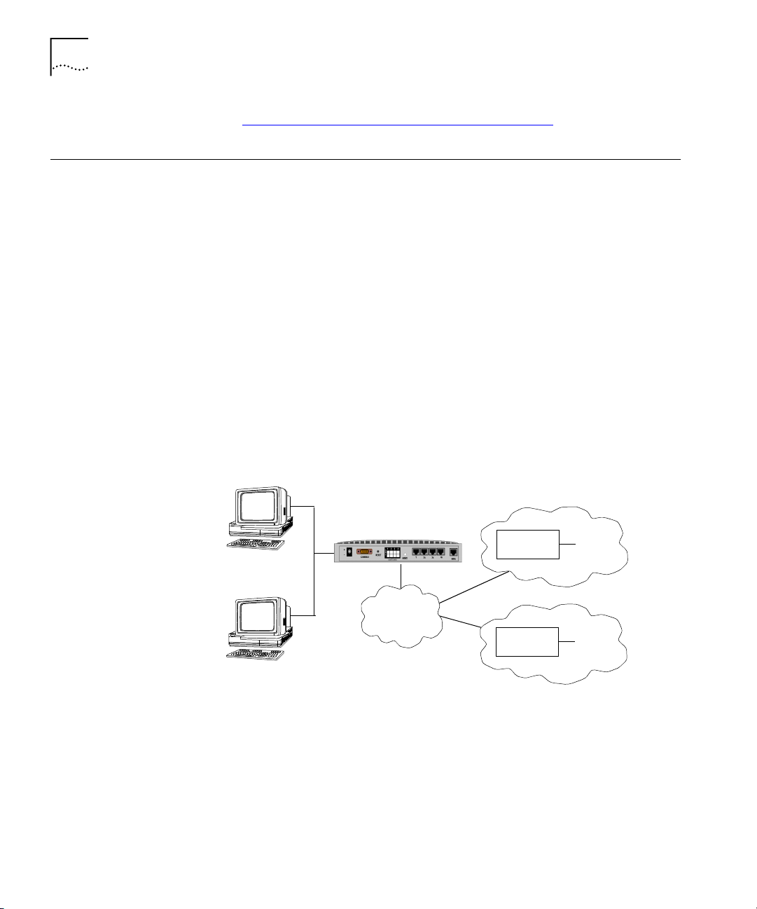
The OfficeConnect Remote 840 allows one or more networked
workstations to connect to other computers on a remote LAN. Once
connected, local users (a local branch office) can communicate with
remote computers (the main office) as if they were connected locally (see
the figure below). The OfficeConnect Remote 840 moves data back and
forth quickly, and accesses any program or file you would ordinarily use
on the network.
Local LAN
OfficeConnect Remote
840 SDSL Router
HTML
Management
ATM
Frame Relay
Edge
Router
Edge
Router
Internet
Remote
Office
Figure 1–1 Connection to Remote Networks
The OfficeConnect Remote 840 can provide high-speed access to the
Internet.
The OfficeConnect Remote 840 provides static and dynamic routing of
the Internet Protocol (IP) and Internetwork Packet Exchange (IPX)
Page 23

What is an SDSL Modem?
1-3
protocols as well as bridging, with support for learning bridge and
802.1d spanning tree functionality to eliminate loops. Other important
features include: Routing Information Protocol (RIP), Simple Network
Management Protocol (SNMP), address translation, telnet, and packet
filtering. The web browser-based OfficeConnect Remote 840 Manager
and the IP Wizard provide a user-friendly configuration interface.
To simplify the installation process, the OfficeConnect Remote 840 can be
initialized with pre-configured parameters using DIP switches located on
the back of the unit. There are three operational modes: DHCP Smart
Mode, Default Bridge Mode, and Unconfigured Mode.
What is an SDSL
Modem?
What is ATM?
An SDSL modem is a device that transmits and receives data through
regular telephone lines at speeds that far exceed traditional analog
modem technology.
It allows your workstation to connect to a remote site using a network
protocol such as IP or IPX. The OfficeConnect Remote 840 contains one
SDSL modem port which is the WAN interface.
Asynchronous Transfer Mode (ATM) is a modern networking technology
that provides support for a wide variety of services and applications. The
OfficeConnect Remote 840 provides support for ATM over SDSL.
ATM is based on the transfer of fixed-length cells containing a header
and an information field. The header is used to route the cells through
the ATM network backbone.
ATM defines connections by two main parameters, which are explained
later in this Guide:
■
Virtual Path Identifier (VPI)
■
Virtual Channel Identifier (VCI).
What is Frame Relay?
Frame Relay is a framed-based technology that runs over HDLC (High
Level Data Link Control). Virtual Circuits are defined which connect the
OfficeConnect Remote 840 to up to 16 remote sites within a Frame Relay
Network. Each Virtual Circuit is identified by a Data Link Connection
Identifier (DLCI), which is included in the frame header.
Page 24

1-4
HAPTER
C
1: O
VERVIEW
What is a BRouter?
A BRouter is an interface between two networks, functioning as a router
and/or a bridge. A router finds the best route between networks and
provides network management capabilities. The OfficeConnect Remote
840 is a protocol independent router that does not rely on the
workstations on a LAN for routing information, such as the destination
location and best route.
Routing vs. Bridging Routers forward packets based on network-level addresses. Bridges
forward packets based on hardware-level, or media access control (MAC)
addresses. In other words, when a router receives a packet from one port,
it looks at the destination network level address (for example, the IP
address) to determine which port to forward the packet to. When a
bridge receives a packet from one port, it looks at the destination MAC
address to determine which port to forward the packet to.
In each case, the unit maintains either a forwarding table (bridges) or a
routing table (routers) that contains information about which port to use
to reach the destination address. These tables are for the most part
maintained automatically by the unit so the administrator does not have
to add or delete entries as the network topology changes.
An example illustrating the difference between bridges and routers would
be the case where both a bridge and a router have tables with 256
entries. Because the bridge forwards based on MAC address, it can know
about the location of 256 MAC addresses (physical machines such as
workstations, servers, etc.). The router can know about the location of
256 networks, where each network can contain many physical machines.
MAC-Encapsulated
Routing
Bridges make forwarding decisions based on destination addresses, while
routers makes forwarding decisions based on networks to which
destination addresses belong. Therefore, routers are more efficient and
capable of handling more traffic.
The OfficeConnect Remote 840 provides a Bridge Firewall function which
allows flexible configuration of simultaneous bridging and routing. For
more information on the Bridge Firewall, see Appendix A, “Bridging and
Routing”.
MAC-Encapsulated Routing enables the OfficeConnect Remote 840 to
function as a router but to work in a bridged environment. When
enabled, the network level addresses are used for forwarding, but the
Page 25
What is a Remote Site?
1-5
MAC layer addresses are pre-pended in the ethernet header over the
Wide Area Connections. Address Resolution procedures (ARP), are used
to dynamically learn the MAC address of the remote router.
What is a Remote
Site?
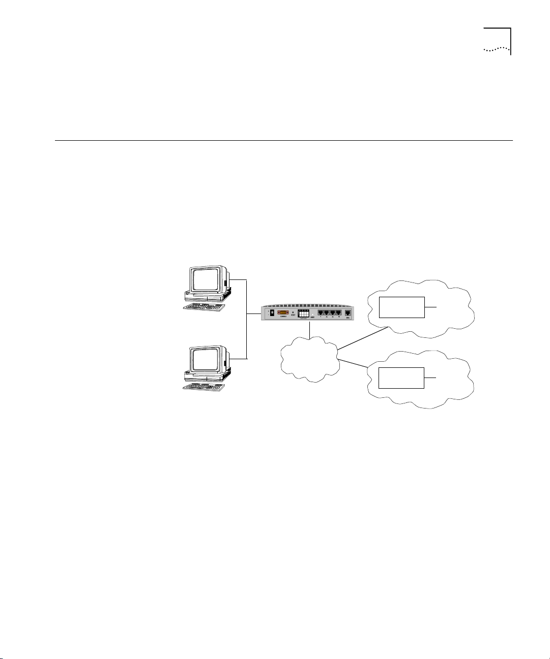
The OfficeConnect Remote 840 can be configured to route IP or IPX,
and/or bridge other protocols between workstations on the Local Area
Network (LAN) and up to 16 remote locations over an ATM or Frame
Relay Wide Area Network (WAN). This is illustrated in the diagram below,
showing the local LAN simultaneously connected to a remote office and
the Internet.
Local LAN
OfficeConnect Remote
840 SDSL Router
HTML
Management
ATM
Frame Relay
Edge
Router
Edge
Router
Internet
Remote
Office
Figure 1–2 Connection to a Remote Internet Network
Data is transmitted to and from remote sites through ATM or Frame
Relay. With ATM, each VC has a configured Quality of Service (QOS) and
is identified by a Virtual Path Identifier (VPI) and a Virtual Channel
Identifier (VCI). With Frame Relay, each Virtual Circuit is identified by a
DLCI. Obtain these parameters from your Service Provider.
The data is framed in either PPP, RFC 1483 or RFC 1490 encapsulation,
which also is specified by your Service Provider.
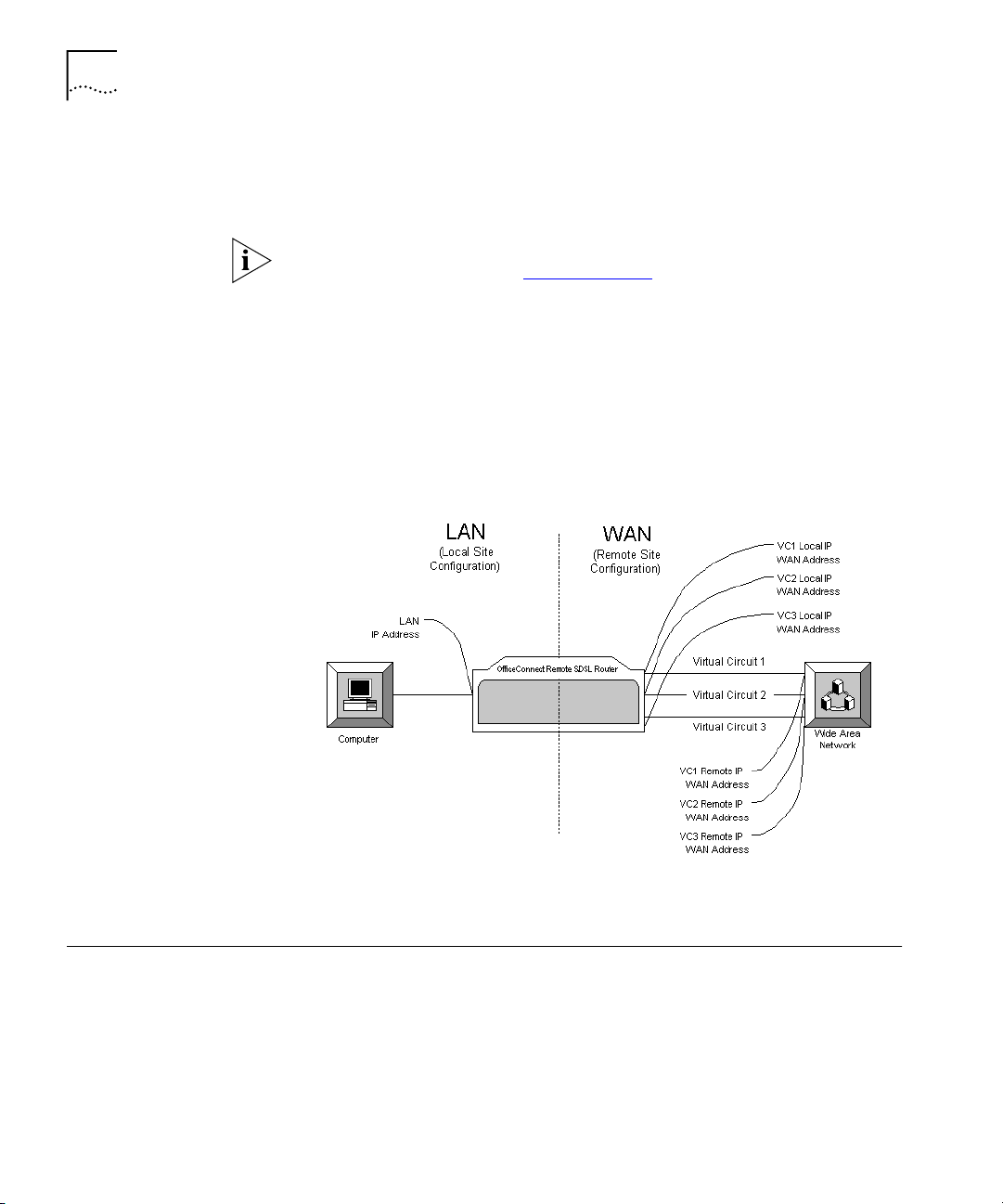
The IP, IPX, and bridge protocols transmit over the ATM VCs. When a
remote site is configured to route IP, there will be a corresponding remote
network IP subnet address and (optionally) a local WAN interface address
Page 26
1-6
HAPTER
C
1: O
VERVIEW
within the same subnet. When the local side of the WAN interface has an
assigned address, it is referred to as being "numbered." Otherwise, it is
referred to as "unnumbered."
For a more in-depth description of “numbered” versus “unnumbered”
interfaces, see Appendix B, “IP Addressing”
.
When PPP is used, both the local and remote WAN addresses can by
dynamically learned. Otherwise, they must be specified. The diagram
below shows a OfficeConnect Remote 840 with 3 VCs and the
corresponding IP addresses.
When PPP is used, both the local and remote WAN addresses can by
dynamically learned. Otherwise, they must be specified. The diagram
below shows an OfficeConnect Remote 840 with 3 VCs and the
corresponding IP addresses.
What is RFC 1483
Figure 1–3 Connection with Three Virtual Circuits (VCs)
RFC 1483 is a protocol standard that describes two encapsulations
methods for carrying network interconnect (Bridging and Routing) traffic
over ATM AAL5.
RFC 1483 is a single-link interface between two packet-switching devices,
such as a bridge or router. An RFC 1483 link may be created between the
OfficeConnect Remote 840 and a remote router after they establish a
Page 27

What is RFC 1490?
connection. RFC 1483 is a conduit for multiple protocols such as IP and
IPX, which are encapsulated and passed across the communications
datalink.
The OfficeConnect Remote 840 supports RFC 1483 and can establish a
RFC 1483 connection to other devices supporting RFC 1483.
1-7
Benefits of Using RFC
1483
What is RFC 1490?
What is PPP?
RFC 1483 offers interoperability of multi-vendor equipment and
identification and aggregation of multiple protocol packets into one data
stream.
It is a protocol standard that describes an encapsulation method for
carrying network interconnect traffic over a Frame Relay backbone. It
covers aspects of both Bridging and Routing.
The OfficeConnect Remote 840 supports RFC 1490 and can establish a
RFC 1490 connection to other devices supporting RFC 1490.
The Point-to-Point Protocol (PPP) is a WAN protocol. It is a single or
multi-link interface between two packet switching devices, such as a
bridge or router. A PPP link may be created between the OfficeConnect
Remote 840 and a remote router after they connect. PPP is an efficient
conduit for multiple protocols such as IP and IPX, which are encapsulated
across the communications datalink.
PPP provides built-in negotiation for addresses and connection
parameters, and it can route multiple protocols over a single link.
The OfficeConnect Remote 840 supports PPP and can establish a PPP
connection to other devices supporting PPP.
Benefits of Using PPP PPP offers interoperability of multi-vendor equipment, and support for
dynamic configuration between the connecting devices.
What is DHCP?
Dynamic Host Configuration Protocol (DHCP) is designed to provide a
centralized approach to configuring IP addresses and parameters.
When a workstation is configured for automatic assignment of IP
addresses, it broadcasts a request on the LAN. The DHCP Server responds
Page 28

1-8
HAPTER
C
1: O
VERVIEW
with an IP address for the workstation and the IP addresses of the default
router and Domain Name Server.
The OfficeConnect Remote 840 can be configured to be a DHCP Server,
with a pool of up to 40 IP addresses.
What is DNS?
What is Address Translation?
A Domain Name Server (DNS) provides an IP address to a host computer
for a given domain name. A DNS Proxy receives requests and attempts to
find an entry in its local tables, and if one is not found, forwards the
request to a remote DNS Server. The remote DNS Server can be learned
dynamically through PPP or can be statically assigned.
The OfficeConnect Remote 840 can be configured as a DNS proxy. A
static local host entry of ocrdsl-3com.com is configured for the
OfficeConnect Remote 840 by default. Therefore, the OfficeConnect
Remote 840 can be easily accessed with a web browser, by typing in
ocrdsl-3com.com in the location or address field in the browser.
In unconfigured mode, ocrdsl-3com.com is not configured by default. In
this mode, you will have to configure a static host entry.
Address Translation allows private network addresses to be mapped into
public addresses. The OfficeConnect Remote 840 provides two methods
for mapping private, non-registered LAN IP addresses to the public
Internet address(es) used for a wide-area connection. The two methods
are:
■
Network Address Translation (NAT). NAT simply substitutes public IP
addresses for private IP addresses.
What is DHCP Smart Mode?
■
Port Address Translation (PAT). PAT allows sessions from multiple
private IP addresses to use a single public IP address.
NAT and PAT can be configured for each remote site.
To simplify the installation process, the OfficeConnect Remote 840 can be
initialized with a set of pre-configured parameters. This operational mode
is referred to as DHCP Smart Mode. In DHCP Smart Mode, the unit will
automatically be assigned an IP address and will provide a pool of IP
addresses to be assigned to each workstation attached to the LAN. When
Page 29

What Is Default Bridge Mode?
you choose this boot option, you will set up your workstation(s) for
automatic IP address assignment.
1-9
What Is Default
Bridge Mode?
What is Unconfigured
Mode?
Getting Started Quickly
The second operational mode is Default Bridge Mode. This mode
preconfigures the unit to bridge all packets. The unit can be automatically
set up so that you will not be required to fill out any forms, use Setup
Wizard, or install any software from the CD unless you want to change
the configuration.
Unconfigured Mode allows you to set all configuration parameters
yourself. You can configure it using Command Line Interface (CLI) (see
the OfficeConnect Remote 840 CLI User’s Guide), or the Web-based
OfficeConnect Remote 840 Manager.
The features described above can be utilized to make configuring the
OfficeConnect Remote 840 very easy.
■
Use DHCP Smart Mode to preconfigure a LAN IP address, the DHCP
pool of addresses, and the DNS information for the LAN workstations.
■
Use Default Bridge Mode to have the unit automatically bridge all
packets. No software installation is required.
■
Use PPP to allow the OfficeConnect Remote 840 to automatically
learn the WAN IP addresses and DNS information.
■
Use PAT to allow the workstations on the LAN to share a single IP
address when accessing the Internet or a remote office.
Use these features together and all you will need to do is enter
authentication and ATM information for your remote site IP connection.
Or:
■
Use Default Bridge Mode to have the unit automatically bridge all
packets. No software installation or configuration is required.
Page 30
1-10
HAPTER
C
1: O
VERVIEW
OfficeConnect Remote 840 Panel Features
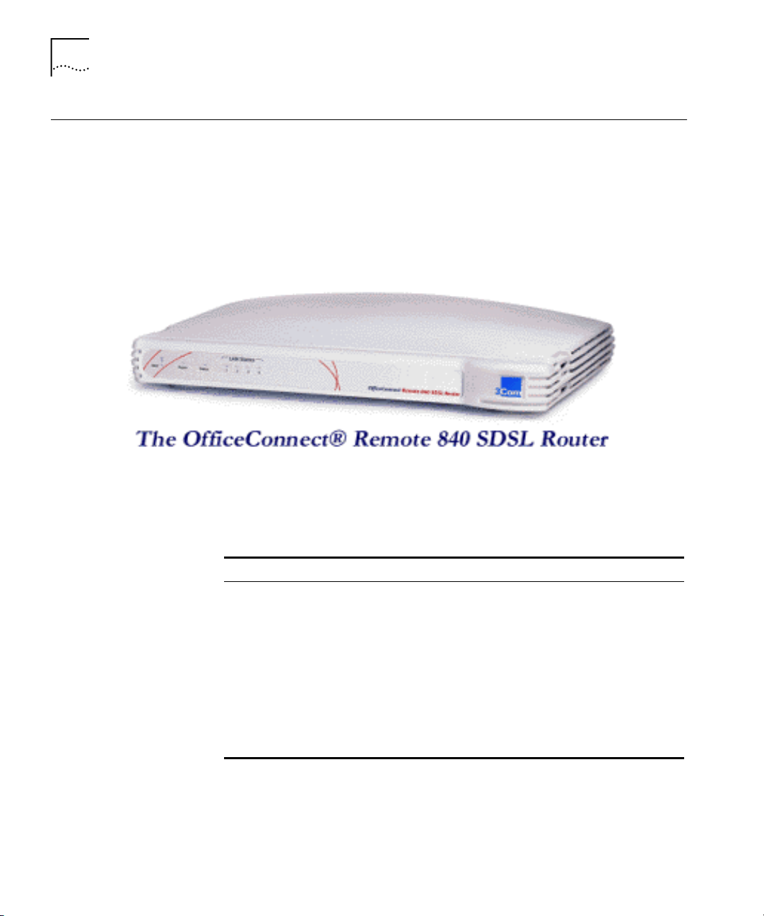
Front Panel Below is a representation of the front panel of your unit:
All LED and status information can be found on the front panel of the
unit, while the power jack and ports are located on the back of the unit.
Figure 1–4 OfficeConnect Remote 840 Front Panel
Table 1–1 LED definitions
LED Status Meaning
Alert FLASHING RED When software is initializing
Power STEADY GREEN When power is applied to the unit
SDSL Link Status OFF No signal detected
FLASHING ORANGE The unit is attempting to acquire
STEADY GREEN Link is up.
FLASHING GREEN When data is being sent over the link.
LAN Status (4) STEADY GREEN When a client is connected to the
synchronization with the CO equipment.
corresponding port on the hub.
A table of LED operation is provided in Chapter 3 of the OfficeConnect
Remote 840 SDSL Router Installation Guide in the section “Installing
The OfficeConnect Remote 840.”
Page 31

OfficeConnect Remote 840 Panel Features
Back Panel Below is a representation of the back panel of your SDSL router:
Figure 1–5 OfficeConnect Remote 840 Back Panel
Power Inlet — The power port attaches to an external, 15-volt DC
■
power supply included with the OfficeConnect Remote 840 package.
The other end of the power supply cable connects to a standard
electrical socket.
Console Port — The DB-9 terminal port connects the OfficeConnect
■
Remote 840 with your console. A straight-through serial cable is
supplied to make the connection.
Reset Button — To reset the OfficeConnect Remote 840 to factory
■
defaults, press this button while rebooting (unplugging and
replugging into an electrical outlet) the unit. You can reset the unit in
Unconfigured Mode, DHCP Smart Mode, or Default Bridge Mode.
(See the Installation Guide for more information on the different
modes.)
1-11
MDI/X Switch — Swaps the transmit (Tx) and receive (Rx) signal pairs
■
on Ethernet port 1. When MDI/X is "out" (not depressed), Port 1 is
pinned the same as the remaining 3 ports. In this mode, a PC's
Ethernet port or the cascade port on another hub can be connected to
any of the four ports on the unit. When MDI/X is pressed "in", then
Port 1 on the unit becomes a cascade hub port, for connection to a
non-cascade port on another hub. The MDI/X button must be "out"
to use Port 1 for connection to a PC.
Ethernet (LAN) Ports (4) — The shielded, 8-pin, RJ-45 Ethernet
■
(10Base-T) ports connect the OfficeConnect Remote 840 with the
LAN. A straight-through cable is supplied in the package to make this
connection. Switches on the back of the unit provide crossover to
allow a direct connection to a single workstation.
SDSL Modem Port — The 4-pin, RJ-11 line port connects your
■
OfficeConnect Remote 840 to the telephone company wall jack. An
RJ-11 modem cable is provided.
DIP (Dual Inline Package) Switches (4) — Switches 1 through 4 can
■
be turned on and off in certain combinations for different
Page 32

1-12
HAPTER
C
1: O
VERVIEW
configurations. See the table below for information about which
switches to set for which configurations.
Table 1–2 DIP Switch Modes
DIP Switch
1 2 3 4 Mode
off off off
off off
on
off
on
off off
off off off off Unconfigured Mode
All other configurations
DHCP Smart Mode — (switch 2 on; all other switches off) This
■
on
Default Bridge Mode, Frame Relay, DLCI = 528, data
encapsulated over RFC 1483.
on
off Default Bridge Mode, Frame Relay, DLCI = 16, data
encapsulated over RFC 1490.
off off DHCP Smart Mode
on
Default Bridge Mode, ATM, One VC define as a bridge,
VPI/VCI = 0/38
: Unconfigured Mode
setting simplifies the configuration process by setting up the
OfficeConnect Remote 840 as a DHCP and DNS server with a fixed IP
address. For more information, see Chapter 2 of the Installation
Guide.
Default Bridge Mode — There are several different settings for
■
Default Bridge Mode. The different settings control the WAN
operational mode; ATM or Frame Relay, and the VPI/VCI or DLCI
settings (see the table above). If you set the OfficeConnect Remote
840 to this mode and no configuration exists, the OfficeConnect
Remote 840 will automatically set up a bridge network on the
Ethernet and will create a VC profile that bridges using RFC 1483 or
RFC 1490 encapsulation with various VPI/VCI or DLCI values (see the
table above for details).
Page 33

Configuration Overview
1-13
Configuration
Overview
General
Configuration Steps
The OfficeConnect Remote 840 configuration is divided into three areas:
Local Site (LAN), Remote Site (WAN), and Global configuration. The
following shows the areas of configuration for each.
Local Site Remote Site Global
IP
IPX
Bridging
Network Service
ATM
IP
IPX
Static WAN Routes
Bridging
DHCP
DNS
Administrative
To successfully configure the OfficeConnect Remote 840 to route or
bridge a network, you should perform the following steps.
The following steps provide an outline to follow when configuring the
OfficeConnect Remote 840 to route or bridge. For detailed instructions
on first time installation and basic configuration, see the OfficeConnect
Remote 840 SDSL Router Install Guide.
Perform the following steps to configure the OfficeConnect Remote 840
to route or bridge a network:
1 Complete the appropriate Configuration Planning Form. A form is
provided in the box when you purchase your OfficeConnect Remote 840.
Copies of the forms are provided in the OfficeConnect Remote 840 SDSL
Router Install Guide for your convenience.
2 Install the OfficeConnect Remote 840 utilities from your OfficeConnect
Remote 840 CD. If necessary, install a web browser on your workstation
(Microsoft Internet Explorer 4 is included on the CD).
3 Connect to the OfficeConnect Remote 840 through either the web
browser or the CLI.
4 Configure the OfficeConnect Remote 840.
■
Ethernet Interface Protocols
■
IP, IPX, Bridging
■
Remote Sites
■
Global Parameters
■
Run the configuration audit.
■
Save the configuration.
Page 34

1-14
HAPTER
C
1: O
VERVIEW
■
Test the network accessibility.
■
Ping a remote site
■
Check the routing tables on configured protocols
How to Manage the OfficeConnect Remote 840
You can manage the OfficeConnect Remote 840 either through the
Command Line Interface (CLI) or through a web browser. If you choose to
manage the unit through CLI, see the OfficeConnect Remote 840 SDSL
Router CLI User's Guide, included on the CD shipped with your unit.
If you choose to use a web browser, you will use the web browser-based
OfficeConnect Remote 840 Manager. This user-friendly system is the
preferred method of management. The OfficeConnect Remote 840
Manager uses the HTTP protocol via a web browser (such as Netscape
Navigator or Microsoft Internet Explorer) to allow you to easily setup and
manage the OfficeConnect Remote 840. In order for the OfficeConnect
Remote 840 Manager to function correctly, you will need to use at least
Netscape Navigator 4.0 or Internet Explorer 3.02. Internet Explorer 4 is
provided on the OfficeConnect Remote 840 Installation CD.
You do not need to be connected to the Internet to use this method.
The main features of the OfficeConnect Remote 840 Manager are:
■
Complete configuration control.
■
Configuration Audit for detecting errors.
■
Troubleshooting and monitoring capabilities.
■
Capability to download software updates.
The OfficeConnect Remote 840 must have an IP address and an
administrative login profile (username and password) in order to connect
to it with a browser. The IP address and administrative login profile are
automatically created when the unit is initially configured using the IP
Wizard or in DHCP Smart Mode or Default Bridge Mode, or the IP address
and administrative login profile can be created using the CLI.
See the OfficeConnect Remote 840 SDSL Router Installation Guide for
information about assigning an IP address and creating an administrative
login profile.
Page 35

Starting the OfficeConnect Remote 840 Manager
1-15
Starting the
OfficeConnect
Remote 840
Manager
OfficeConnect Remote 840 Manager Menus
To access the OfficeConnect Remote 840 Manager, either enter the unit's
LAN IP address or DNS host name into the Location or Address field of
your web browser. When entering the IP address or DNS host name you
do not have to enter http:// (i.e., you can enter http://192.168.200.254 or
simply 192.168.200.254).
If you initially configured your unit with DHCP Smart Mode, your unit will
have an IP address of 192.168.200.254 and a DNS host name of
ocrdsl-3com.com.
When prompted to login to the unit, enter the administrative login name
and password. After successful authentication, you will access the
OfficeConnect Remote 840 Manager "home page."
The OfficeConnect Remote 840 Manager is a hierarchical menu-based
interface. The highest level page in the hierarchy is the OfficeConnect
Remote 840 Manager home page. The home page displays a list of five
menu choices:
■
Setup Wizard
■
Online Guide
■
Tools
■
Configuration
■
Monitor
Each of the 5 main menus contain sub-menus with more choices.
Page 36

1-16
HAPTER
C
1: O
VERVIEW
Using the OfficeConnect Remote 840 Manager
All OfficeConnect Remote 840 Manager screens have three basic areas:
Header
Quick Link Area Main Area
Header — Shows the title of the current page being accessed.
■
Quick Link Area — Indicates the position of the current page in the
■
OfficeConnect Remote 840 Manager menu hierarchy and provides
links which allow quick access to the home page and the five menu
options. This allows you to quickly go from one menu area to another,
such as from Configuration to Monitor.
Main Area — Displays the current page containing configuration or
■
status information.
To access a particular OfficeConnect Remote 840 Manager page follow
the links through the menu hierarchy in the Main area. You can use the
Quick Link area to quickly get back to the top of the menu hierarchy or to
one of the five menu options selections.
You can configure your web browser's link display options to customize
the colors of the Quick Links.
Document Notation References to specific OfficeConnect Remote 840 Manager pages in this
document will use a specific notation to describe the location of a page
relative to the OfficeConnect Remote 840 Manager home page. The
notation uses the “>“ character to indicate that a sub-menu on a page
must be accessed.
For example, to monitor the IP ARP Table you would (starting from the
home page) access the Monitor menu. From the Monitor menu you
would access the Networks sub-menu. From the Networks sub-menu
you would access the IP sub-menu. Finally, from the IP sub-menu, you
would access the ARP Table page. This is specified as Monitor >
Networks > IP > ARP Table.
Page 37

Where to Find More Configuration Information
Online Help The OfficeConnect Remote 840 Manager provides two methods of
obtaining help.
■
The Online User's Guide. This guide contains detailed information
about configuring and using your OfficeConnect Remote 840. You
can access the Online User's Guide from the OfficeConnect Remote
840 Manager home page.
■
A detailed HTML help screen is available for each configuration page.
There is a Help button at the bottom of each page requiring manual
data entry or selection. The help text describes the valid values for
each data entry field that may be entered on the current screen.
The Online User’s Guide and HTML help screens are not part of the
OfficeConnect Remote 840 operational software. They must be installed
on each workstation where you will run your OfficeConnect Remote 840
Manager browser. That is, if you have two workstations from which you
will run the OfficeConnect Remote 840 Manager, and if you want access
to the Online Guide and screen HTML help screens, you must run the CD
installation at both workstations.
1-17
Where to Find More
Configuration
Information
See the referenced chapters of this Guide to help you perform the
following tasks:
■
Administrative Tasks such as updating software or controlling login
access — “System Administration”
■
IP Routing Parameters — “Configuring IP Routing”
■
IPX Routing Parameters — “Configuring IPX Routing”
■
Bridging Parameters — “Configuring Bridging”
■
How to Monitor the OfficeConnect Remote 840 SDSL Router —
“Monitoring the OfficeConnect Remote 840”
■
Configuring the OfficeConnect Remote 840 either for accessing the
Internet or for Telecommuting / Remote Access – OfficeConnect
Remote 840 SDSL Router Install Guide, Chapter 3.
Page 38

1-18
HAPTER
C
1: O
VERVIEW
Page 39

2
YSTEM
S
DMINISTRATION
A
Performing System Administration Ta s k s
Controlling Login and Telnet Access
This section describes the details for performing the following System
Administration OfficeConnect Remote 840 Manager tasks:
■
“Controlling Login and Telnet Access”
■
“Modifying the Date and Time”
■
“Restoring Factory Defaults”
■
“Updating OfficeConnect Remote 840 Software”
■
“Controlling SNMP Access”
■
“Controlling TFTP Access”
■
“Assigning SNMP Trap Managers”
■
“Assigning Syslog Managers”
This allows you to set up management access security. The configured
username and password combination allows web browser and Telnet
access. Connecting to the OfficeConnect Remote 840 with a web
browser allows you to configure and monitor your unit using the
OfficeConnect Remote 840 Manager. Connecting using Telnet on a
workstation allows you to remotely manage the unit using CLI.
A default user name of root and password !root are provided by DHCP
Smart Mode and the IP Wizard during the initial installation. For secure
access, you should add a private login name and password and delete the
default name.
Page 40

2-2
HAPTER
C
Adding a Login
Deleting a Login
YSTEM ADMINISTRATION
2: S
1 From the home page, select Configuration > Global > Administrator
2 Enter the following fields:
3 After the fields have been entered, click Submit. To clear the fields, click
> Login. Click Add. The following screen fields appear:
User Name — Enter the login or Telnet username in this field.
■
Password — Enter the login or Telnet password in the field.
■
Reset.
1 From the home page, select Configuration > Global > Administrator
> Login. Click Add. The following screen fields appear:
2 Select the login name to be deleted.
3 Click Delete.
Page 41

Modifying the Date and Time
2-3
Modifying the Date
and Time
Restoring Factory Defaults
This allows you to modify the system date and time.
1 From the home page, select Configuration > Global > Administrator
> Date and Time. The screen with the following fields appear:
2 Enter the date and time information, utilizing the correct formats as
shown next to the fields.
3 After the fields have been entered, click Submit. To clear the fields, click
Reset.
Restoring the OfficeConnect Remote 840 to factory defaults causes all
configuration information to be deleted and the unit to be rebooted.
To check the boot mode, go to the Configuration > Global >
Administrator > System screen.
If you boot to the unconfigured state, you will need to run IP Wizard or
use CLI to reassign an IP address to your OfficeConnect Remote 840. If
you boot in DHCP Smart Mode, the IP address will be set to
192.168.200.254.
If you boot in Default Bridge Mode, you may not need an IP address
assigned to the unit. However, if you do want one, you must use
Command Line Interface. For detailed instructions on using CLI, please
see the OfficeConnect Remote 840 CLI User's Guide, printable or
viewable from the OCR840 CD.
You can set the switches before you restore the defaults to have the
OfficeConnect Remote 840 boot in the mode you wish. See Table 1–2,
DIP Switch Modes in Chapter 1 to select the mode you wish.
There are two ways to restore factory defaults:
■
OfficeConnect Remote 840 Manager.
Page 42

2-4
HAPTER
C
YSTEM ADMINISTRATION
2: S
■
Reset button on the back of the unit.
Using the OfficeConnect Remote 840 Manager to Restore Defaults
Using the Reset
Button
1 Select Tools > Reboot.
2 Select the Delete all configuration and reboot device information
option.
3 Click Submit.
4 Wait one minute. Then, configure an IP address if DHCP Smart Mode is
not in use.
5 Open up the web browser and start the OfficeConnect Remote 840
Manager by entering the new IP address in the browser
location/address box.
1 Turn the OfficeConnect Remote 840 off by unplugging the unit.
2 At this time, set the DIP switches to their appropriate settings (DHCP
Smart Mode, Default Bridge Mode, or Unconfigured Mode). If you
select Unconfigured Mode, you can set one of the other modes later
using CLI or the OfficeConnect Remote 840 Manager.
3 While holding down the Reset button on the back panel, plug the
unit back in. You should hold down the reset button for at least five
seconds after plugging the unit back in. The unit takes about one
minute to come up and the Alert LED will flash until bootup is finished.
4 If DHCP Smart Mode is not in use, configure an IP address after the
unit comes up.
Updating OfficeConnect Remote 840 Software
Controlling SNMP Access
5 Open up the web browser and start the OfficeConnect Remote 840
Manager by entering the new IP address in the browser
location/address box.
See “Upgrading Operational Software for the OfficeConnect Remote
in Chapter 10 for information on updating the operational and
840”
system software.
The Simple Network Management Protocol (SNMP) is used for
managing routers and other network devices from a central station or
Page 43

Controlling SNMP Access
2-5
stations. These stations, the SNMP Managers, query the managed units
for configuration and monitoring information.
The OfficeConnect Remote 840 can be managed by SNMP Managers in
read-only or read-write mode.
Using SNMP to manage the OfficeConnect Remote 840 is more
complicated than the preferred method of management, the
OfficeConnect Remote 840 Manager.
SNMP access is provided by an SNMP community name and access mode.
To Download the Management Information Base (MIB) files, go to the
website, http://www.3com.com/support/ocr840/index.html, and click
the drop-down menu under software/MIB downloads.
To set up an SNMP community on the OfficeConnect Remote 840, follow
these instructions:
1 From the home page, select Configuration > Global > Administrator
> SNMP. Click Add and the following screen fields appear:
2 Enter the following fields:
Name — Enter the community name to be used as the access name.
■
Address — Enter the address of the SNMP server (e.g.,
■
192.168.200.52).
Specifying 0.0.0.0 allows any SNMP server access if they supply the
correct name.
Access — Check the box for Read Only or Read & Write. Read Only
■
allows only the user to view the screens.
3 After the fields have been entered, click Submit. To clear the fields, click
Reset.
Page 44

2-6
HAPTER
C
YSTEM ADMINISTRATION
2: S
4 Repeat steps 1-3 for each management station which is a part of this
5 To alter previously set Access Rights, follow step 1 and select the
6 To delete a management station from a community, go to the home page
community.
Be careful to have the Access box checked the same for each new
member of the community.
The entire community will be given the access rights of the last member.
community from the community list and click Modify.
and, select Configuration > Global > Administrator > SNMP. Select
the community and management station from the lists and click Delete.
Controlling TFTP Access
The Trivial File Transfer Protocol (TFTP) provides a simple way to
transfer files from one machine to another. The OfficeConnect Remote
840 has a TFTP server that allows you to copy files to or from the unit. All
you have to do is set up TFTP access on the OfficeConnect Remote 840
and run a TFTP client program on a workstation. TFTP transfers files over
either the LAN or WAN interfaces.
To configure the OfficeConnect Remote 840 to provide TFTP access,
follow the instructions below:
1 From the home page, select Configuration > Global > Administrator
> TFTP. Click Add and the following fields appear:
2 Enter the address of the client workstation or select Any Client for
unrestricted client access.
3 After the fields have been entered, click Submit. To clear the fields, click
Reset.
Page 45

Assigning SNMP Trap Managers
2-7
Assigning SNMP
Trap Managers
An SNMP trap is an event that causes the OfficeConnect Remote 840 to
send an unsolicited message to a SNMP manager.
These events are generally critical events that indicate an operational
problem. (Critical events can also be viewed on the OfficeConnect
Remote 840 Manager's Monitor > Events > Critical Event Log screen.)
To configure the OfficeConnect Remote 840 to send traps, follow these
instructions:
1 From the home page, select Configuration > Global > Administrator
> TRAP. Click Add and the following screen fields appear:
2 Enter the following fields:
Name — Enter the name of the SNMP Trap Manager.
■
Address — Enter the address of the SNMP Trap Manager (e.g.,
■
192.168.200.50).
Specifying 0.0.0.0 causes SNMP Traps to be broadcast.
3 After the fields have been entered, click Submit. To clear the fields, click
Reset.
To alter previously set fields, follow step 1 and select an SNMP Trap
Manager, then click Modify. To delete a server from your configuration,
select an SNMP Trap Manager from the TRAP screen and click Delete.
Page 46

2-8
HAPTER
C
YSTEM ADMINISTRATION
2: S
Assigning Syslog Managers
A Syslog manager is a workstation that accepts and saves informational
messages from a network device. The OfficeConnect Remote 840
Manager can be configured to send log messages to a syslog manager as
follows:
1 From the home page, select Configuration > Global > Administrator
> Syslog. Click Add and the following screen fields appear:
2 Enter the following fields:
Syslog Host IP Address — Enter the address of the Syslog host.
■
System Level — Select one of the following levels: Critical, Unusual,
■
Common, Verbose, and Debug.
3 After you enter the fields, click Submit. To clear the fields, click Reset.
Page 47

3
EMOTE
R
S
ITE
ANAGEMENT
M
Introduction
Remote Site Overview
This chapter provides an overview on managing remote site profiles using
the web browser based OfficeConnect Remote 840 Manager. If you need
information on setting up or initially configuring the unit, see the
OfficeConnect Remote 840 SDSL Router Installation Guide. This section is
divided into the following parts:
■
“Remote Site Overview”
■
“Managing a Remote Site Profile”
■
“Configuring Network Service Information (PPP / RFC 1483 / RFC
1490)”
■
“Configuring ATM Information”
■
“Configuring Protocol Parameters”
■
“Monitoring Remote Site Connections”
To set up connections over the WAN, a remote site profile must be
created and edited for each remote location you want to connect to.
With this profile, you specify ATM virtual circuit or Frame Relay DLCI
information, protocols, and addresses that determine the method of
connection and communication to the remote site.
You first need to add a remote site profile, and then you modify the
profile to include WAN connection and network information.
The following list summarizes the necessary information.
WAN — Network Service (PPP / RFC 1483/RFC 1490) information, and
■
ATM Virtual Channel (VC) or Frame Relay (DLCI) information
IP — IP addresses, address translation tables, static routes, and RIP
■
usage.
Page 48

3-2
HAPTER
C
EMOTE SITE MANAGEMENT
3: R
■
■
If you need to connect to multiple remote sites such as the Internet and a
remote office, you should set up a remote site profile for each location.
IPX — IPX network address information, static routes and services,
and RIP usage.
Bridging — Bridging (enable / disable) to the remote site.
Managing a Remote Site Profile
Adding a Remote Site
Profile
Once created, remote site profiles can be enabled or disabled. When a
profile is enabled, the OfficeConnect Remote 840 reads the connection
parameters for the remote site from the profile and continuously
attempts to establish a connection to the remote site.
When a profile is disabled, the connection will be terminated and no
other data will be directed to the remote site.
Configuration changes to a remote site profile do not take effect until the
next time the profile is enabled. The OfficeConnect Remote 840 Manager
automatically disables and re-enables the remote site profile when the
Modify button is pressed on the Remote Site menu page.
To disable or enable a profile manually, clear or check the Enable
Remote Site checkbox as appropriate.
Once you start modifying a Remote Site, you must click Modify before
you exit the Remote Site screens, or else the data you entered will be lost.
Also, remember to save your configuration before rebooting your
OfficeConnect Remote 840 so that your changes will be written to
permanent FLASH memory.
1 From the OfficeConnect Remote 840 Manager home page, select
Configuration > Remote Sites (WAN). Then click the Add button to
bring up the Remote Site General Add screen.
2 Enter the Remote Site Name. Enter a name to use to identify the remote
site profile. (Ex: ISP or CorpOffice)
3 Ensure that the Enable Remote Site box is checked if you want to the
connection to come up as soon as you finish the configuration.
Page 49

Modifying a Remote
Site Profile
Managing a Remote Site Profile
3-3
4 Click Add. Then click Save Configuration on the sidebar to
permanently save the changes.
The Network Service (PPP and RFC 1483/ RFC 1490), ATM, and network
protocol (Bridging, IP, and IPX) information has not been configured yet.
To make a connection with the remote site you must configure the
Network Service, ATM, and at least one network protocol. (See
“Configuring Network Service Information (PPP / RFC 1483 / RFC 1490)”
“Configuring ATM Information”
, and “Configuring Protocol Parameters”
for details.)
1 From the OfficeConnect Remote 840 home page, select Configuration
> Remote Site (WAN).
2 Select the name of a remote site profile and click Modify. This brings up
the Remote Site General Modify screen.
3 Change configuration parameters as needed and use the Next button to
continue to the ATM , IP, IP Advanced, and IPX configuration screens.
,
Deleting a Remote
Site Profile
For quick help on specific parameters, click the Help button located at
the bottom of each screen.
For more detailed help, go to the appropriate place in this guide (see
“Configuring ATM Information”
and Configuring Other WAN
Parameters).
■
Click Modify on any screen to set all the Remote Site parameters.
■
Click Save Configuration on the sidebar to permanently save the
changes.
1 From the OfficeConnect Remote 840 home page, select Configuration
> Remote Site (WAN).
2 Select the name of a remote site profile and click Delete. This brings up
the Remote Site General Delete screen.
3 To delete the profile, click Delete. To return to the remote site profile
selection list, click Prev.
Page 50

3-4
HAPTER
C
EMOTE SITE MANAGEMENT
3: R
Configuring
Network Service
Information (PPP /
RFC 1483 / RFC
1490)
A Network Service defines the data encapsulation and protocol
characteristics for the connection between two packet switching devices.
The OfficeConnect Remote 840 supports PPP, RFC 1483 and RFC 1490
Network Services. The OfficeConnect Remote 840 and the remote site
must both use the same Network Service in order for a connection to be
established.
For PPP, the authentication name and password must be provided to
allow the connection to be established. The OfficeConnect Remote 840
supports both PAP and CHAP authentication.
The Network Service parameters can be configured on the Remote Sites
General screen.
1 Access this screen by going to the OfficeConnect Remote 840 home
page. Select Configuration > Remote Sites (WAN), select a defined
remote site and click Modify.
2 This will access the Remote Sites General Modify Screen.
3 If your unit is using ATM, the Remote Sites General Modify Screen will
contain the following fields:
Page 51

Frame Relay
Configuring Network Service Information (PPP / RFC 1483 / RFC 1490)
4 Select the network service to be either RFC 1483, or PPP.
If PPP, enter the Authentication Name and Authentication Password
provided to you. You can change the header compression from the
default of none to TCP/IP if you wish.
5 Click Next to proceed to the ATM Configuration screen.
1 If your unit is using Frame Relay, the Remote Sites General Modify
screen will contain the following fields:
3-5
2 Enter a name to identify the remote site.
3 Select Network Service to either PPP over Frame Relay or RFC 1490.
If you select PPP over Frame Relay, enter the Authentication Name and
Authentication Password provided to you. You can change the header
compression from the default of None to TCP/IP if you wish.
4 Enter the DLCI.
5 Check the Enable Bridging and Enable MAC Encapsulated Routing
boxes according to your service provider’s directions.
Page 52

3-6
HAPTER
C
EMOTE SITE MANAGEMENT
3: R
6 Check the Enable Remote Site box.
Configuring ATM Information
The ATM parameters are supplied by your service provider. These
parameters consist of:
■
ATM VC information
■
ATM Category of Service parameters
ATM allows for permanent connections (PVCs) and switched connections
(SVCs). For a PVC, the required VC information parameters consist of the
Virtual Path Identifier (VPI) and Virtual Channel Identifier (VCI).
The VPI / VCI uniquely specify the path to the remote site and are placed
in the ATM cell header that is used to route each cell to the remote site.
Two remote site profiles with the same VPI and VCI cannot be active
simultaneously. You may encounter this situation if you want to log in to
the same remote site with different PPP authentication parameters. You
should disable all profiles using the same VPI / VCI and then enable the
one that should be active.
For SVCs, there is not a fixed VPI / VCI. Instead, a destination address is
used to set up a path through the ATM backbone network when the
connection is to be established. Currently, the SVC capability is disabled in
the OfficeConnect Remote 840.
ATM Category of Service parameters specify characteristics (also referred
to as traffic shaping) of data transmitted from the OfficeConnect Remote
840 to the remote site. They have no effect on data transmitted from the
remote site to the OfficeConnect Remote 840.
ATM Modify Screen Go to Configuration > Remote Sites (WAN). Select a site from the list
and click Modify.
Click Next to proceed to the ATM Modify screen. The screen contains
the following fields:
Page 53

Configuring ATM Information
■
If PVC is selected, enter the VPI and VCI.
VPI — The Virtual Path Identifier (VPI) is part of the cell header for
■
the cells that are transferred over this connection.
3-7
VCI — The Virtual Channel Identifier (VCI) is part of the cell header
■
for the cells that are transferred over this connection. If you are
configuring multiple VCs, enter the number of the respective VC in
this field.
■
If necessary, enter any Category of Service parameters that have been
provided to you.
UBR — Unspecified Bit Rate; no limit has been specified for the
■
rate for information flow.
VBR — Variable Bit Rate; a certain rate has been specified for the
■
flow of information.
CBR — Constant Bit Rate; a constant rate has been specified for
■
the flow of information.
■
Enter the cell rate transmission parameters, if applicable.
PCR — The Peak Cell Rate is the maximum amount of cells per
■
second transmitted over this connection. This is determined by the
minimum intercell spacing in seconds, which is the time interval
from the first bit of one cell to the first bit of the next cell.
SCR — The Sustainable Cell Rate, in cells/second. This is the rate at
■
which cells are transmitted over this connection. This is the
Page 54

3-8
HAPTER
C
EMOTE SITE MANAGEMENT
3: R
If no traffic shaping parameters have been provided you should choose
the default parameter of UBR with a PCR value of 0. The OfficeConnect
Remote 840 will attempt to use all of the upstream bandwidth when
transmitting data to the remote site.
maximum average rate or cells that are sent in bursts at a peak
rate.
BT — The Burst Tolerance (also referred to as Maximum Burst Size),
■
in cells/second. This is the maximum number of cells that can be
sent at the peak rate.
Configuring Protocol Parameters
Monitoring Remote Site Connections
There are more WAN connection parameters that can be configured, such
as IP routing, IPX routing, Bridging, and Address Translation. Instructions
for configuring these parameters are located in:
■
“Configuring IP Routing”
■
“Configuring IPX Routing”
■
“Configuring Bridging”
■
“Network Address Translation Using the OfficeConnect Remote 840”
■
To determine which remote sites have been configured and to see a
summary of the remote site WAN parameters, access the Monitor >
Remote Sites > Remote Site Status screen.
■
To monitor packet counters for a specific remote site, access the
Monitor > Remote Sites > Remote Site Counters screen. (Remote
Site Counters are only applicable for active connections.)
■
To determine whether a remote site connection has been established
or to determine why a connection is not working properly, check the
connection event log. This log is accessed at Monitor > Events >
Connection Event Log.
■
To monitor throughput for all active remote sites, access the Monitor
> ATM Throughput screen.
For more information on these and other monitoring capabilities, see
Chapter 11, “Monitoring the OfficeConnect Remote 840”
.
Page 55

4
ONFIGURING
C
IP R
OUTING
Introduction
Overview
This chapter contains information on configuring routing for IP protocol
using the OfficeConnect Remote 840. It is divided into the following
sections:
■
“Overview”
■
“Enabling IP Routing”
■
“Configuring IP for the LAN”
■
“Configuring IP RIP on the LAN”
■
“Configuring IP for the Remote Site Connection”
■
“Configuring IP RIP on a Remote Site”
■
“Configuring IP Static and Framed Routes”
■
“Using IP Address Validation”
■
“Monitoring”
■
“IP Testing (PING)”
The OfficeConnect Remote 840 can be configured as a router to forward
packets between the local LAN interface and one or more Remote Sites.
The router maintains a forwarding table. This table specifies which
interface to route an IP packet based on the destination IP address.
Entries in the forwarding table are either static or dynamic. Static entries
are based on the LAN's and Remote Site's subnet addresses and user
configured static routes. Dynamic entries are added when Routing
Information Protocol (RIP) is enabled and routes are learned from
neighboring routers.
The OfficeConnect Remote 840 does not support OSPF (Open Shortest
Path First) protocol.
Page 56

4-2
HAPTER
C
4: C
ONFIGURING
OUTING
IP R
To configure IP routing, IP must be defined on both the LAN interface and
one or more remote sites. On the LAN, an IP network must exist and it
must have a specified IP address and subnet mask. On the remote sites, IP
routing needs to be enabled, and the remote router address, a remote
subnet mask and local WAN interface address need to be configured. The
remote site address configuration can be learned dynamically when the
remote site connection is established if the network service is PPP,
otherwise it has to be specified.
Enabling IP Routing
Configuring IP for the LAN
When the OfficeConnect Remote 840 is to be used for IP Routing,
forwarding must be enabled in the global IP setting.
Access the IP Screen through Configuration > Global > IP > IP
Settings. This screen contains the following fields:
Check the Forwarding box to enable the routing of IP packets.
In addition to Forwarding, the RIP check box is used to enable or disable
RIP for all Remote Sites and the local LAN. If RIP is globally disabled, it is
disabled for the local LAN and Remote Sites on the OfficeConnect
Remote 840. If RIP is globally enabled, it can be enabled or disabled on
the local LAN and for each Remote Site.
To configure IP over the LAN, assign an IP network to the LAN port by
providing a name and a network address. After adding a network, you
can modify advanced parameters.
If you ran the IP Wizard or booted the unit in DHCP Smart Mode, an IP
network has already been added over the LAN port. Its name is IP and its
address is either entered from the IP Wizard or it is 192.168.200.254. You
can view or modify configuration parameters for this network (e.g.,
Enable RIP).
If you use this IP address for accessing the OfficeConnect Remote 840
Manager, be careful not to delete the network.
Page 57

Configuring IP for the LAN
4-3
For routing to take place across the OfficeConnect Remote 840, you also
have to set up a corresponding network over the WAN port (see
“Configuring IP for the Remote Site Connection”
).
Use the Configuration > Local Site (LAN) > IP screen to define or
modify all IP networks over the LAN. Note that all IP networks defined
over the LAN only support Ethernet II framing.
Adding a Local IP
Network
You may add multiple IP networks over the Ethernet interface by
following these steps:
Select Configuration > Local Site (LAN) > IP.
Click Add. This brings up a screen containing the following fields:
Enter the following information:
Name — The name is limited to 32 characters. If you use any blank
■
spaces, surround the whole phrase with double quotes (e.g., “test site
x”).
LAN Address — Enter the address of the IP network in this format:
■
ddd.ddd.ddd.ddd where ddd is a value between 1--255.
LAN Mask — Enter the mask of the IP network in this format:
■
ddd.ddd.ddd.ddd where ddd is a value between 0--255.
By default, RIP is not enabled for this new IP network. If you wish to
enable RIP, proceed to the Modify portion of the following section.
Click Add when you have entered these fields. This returns to the IP
menu screen.
Page 58

4-4
HAPTER
C
4: C
ONFIGURING
IP R
OUTING
Resetting Parameters If you need to return to the original parameters for this screen, click
Reset before you click Add.
Modifying or
Deleting an IP
Network
To modify information pertaining to an existing IP network, or to delete
that information from your configuration, follow these steps:
1 Proceed to the IP screen, following steps from the previous section.
2 Select an IP network you wish to modify or delete.
3 Click Modify/Delete.This brings up the IP Modify/Delete screen
containing the following fields:
4 Modify or delete the information about the selected IP network by
altering the fields and clicking the Modify/Delete button.
If you alter the address that your browser is using, the connection will be
lost. To reconnect, enter the new IP address in your browser's
address/location field. If you delete the address, you will also lose the
connection. You will not be able to reconnect until a new address is
assigned using either the IP Wizard, CLI, or by rebooting in DHCP Smart
Mode.
5 If you need to return to the original parameters for this screen, click
Reset before you click Modify.
Page 59

Configuring IP RIP on the LAN
4-5
Configuring IP RIP
on the LAN
RIP is utilized as a means of communicating routing information between
routers. This is done to keep the routers updated on information.
Local Site (LAN) RIP The RIP options for the LAN can be accessed through Configuration >
Local Site > IP. Select a defined local site connection from the list and
click Modify/Delete, which accesses the IP Modify/Delete screen,
containing the following fields:
You can then select the RIP version to be either None, RIPV1, or RIPV2.
You can also modify the Advanced RIP parameters. You should not need
to change any of these parameters from the defaults, but you can if
necessary.
Advanced RIP
Modification Options
Select a local site connection from the list on the main IP screen, and click
Advanced.
Page 60

4-6
HAPTER
C
4: C
ONFIGURING
IP R
OUTING
This brings up a screen containing the following fields:
1 You may enter the following fields:
■
Broadcast Address - Check one of two options: All Ones or All Zeroes.
■
Max Reassembly - Enter the maximum value that your network cannot
exceed for this function.
Resetting Parameters
2 Under the following two categories, you may customize your RIP:
■
Advanced RIP Policies - You may enable these options as necessary.
They control what is sent out or received concerning RIP.
3 Click Submit when the fields have been entered to save your
customizations.
If you need to return to the original parameters for this screen, click
Reset before you click Add.
Page 61

Configuring IP for the Remote Site Connection
4-7
Configuring IP for
the Remote Site
Connection
Configuring IP
Parameters for the
Remote Site
To set up connections over the WAN, a remote site profile must be
created and edited for each remote location you want to connect to.
With this profile, you specify ATM virtual circuit information, protocols,
and addresses that determine the method of connection and
communication to that remote site.
You first need to add a remote site profile, then modify the profile to
include WAN connection and network information. The following list
summarizes the necessary information:
Frame Relay/ATM WAN — Network Service (PPP/RFC 1483/ RFC
■
1490) information, ATM VC information
IP — IP addresses, address translation tables, static routes, RIP usage
■
IPX — IPX network address information, static routes and services, RIP
■
usage
Bridging — Enable or disable bridging to the remote site
■
If you need to connect to multiple remote sites (i.e., the Internet and a
remote office) you should set up a remote site profile for each location.
The following steps illustrate how you configure the IP parameters of the
remote site profile.
These instructions assume you have already added a remote site profile. If
you need to add a remote site profile, select Add instead of Modify in
step 1.
1 Access this screen by going to the OfficeConnect Remote 840 home
page. Select Configuration > Remote Sites (WAN), and click Modify.
This will access the Remote Sites General screen.
2 Continue clicking Next to advance through the ATM Modify screen to
the IP Modify screen.
Page 62

4-8
HAPTER
C
4: C
ONFIGURING
IP R
OUTING
Configure the
Remote Site IP
Network Information
The following steps illustrate how you configure the remote site IP
network information.
1 Complete the following entries:
Local WAN IP Address:
■
If you were provided a single IP address, select Specified and enter
that address.
■
If you are using PPP to dynamically assign an address, select Dynamic,
and the remote site on the WAN will assign a local WAN IP address to
the WAN port of your OfficeConnect Remote 840.
■
Otherwise, select Unnumbered, and there will be no IP address
assigned to the local WAN interface for this VC.
Page 63

Configuring IP for the Remote Site Connection
4-9
Remote WAN IP Address:
■
If you were provided a remote IP address and netmask, select
Specified and type in that address and netmask.
■
If the OfficeConnect Remote 840 is learning the remote IP address
from the remote site (PPP only), select Learn from Remote.
2 In order to have the remote site you are configuring as the default
gateway, check the Use Remote as Default Gateway checkbox.
3 If you are routing IP traffic to multiple remote sites, select one to be your
default gateway. Then check this box only in the profile for that remote
site.
4 Select from the pull-down menu to have the RIP set to Broadcast, Listen,
or Broadcast & Listen, and if one of these is chosen, set the RIP option to
RIPV1 or RIPV2.
If you are using address translation (PAT / NAT), you must set routing to
either Listen or None. This is because you have set up a private network
and therefore do not want to be broadcasting information to other
routers.
5 Ensure that Enable IP is checked (enabled) and click Modify.
You are now done configuring the basic IP information for the Remote
Site Connection.
Further Remote Site IP Configuration information is available in the
following sections:
■
Address Translation information is available in “Network Address
Translation Using the OfficeConnect Remote 840”.
■
Address Validation Information is available under “Using IP Address
Validation”.
Page 64

4-10
HAPTER
C
4: C
ONFIGURING
IP R
OUTING
Configuring IP RIP on a Remote Site
Access the RIP options for the WAN through Configuration > Remote
Sites > IP.
1 Select a defined remote site connection from the list and click Modify.
Keep clicking Next until you advance to the IP Modify screen.
2 You can select the RIP version to be either Broadcast, Broadcast &
Listen, Listen or None. Broadcast refers to when routing information
packets are sent out to the network, and Listen refers to the
OfficeConnect Remote 840 receiving routing information packets from
remote sources.
If you are using address translation (PAT/NAT), you must set routing to
either Listen or None. This is because you have set up a private network
and therefore do not want to be broadcasting information to other
routers.
3 You can then choose between RIPV1 (version 1) or RIPV2 (version 2) for
your routing information protocol.
Page 65

Configuring IP Static and Framed Routes
4-11
Configuring IP
Static and Framed
Routes
Adding a Static IP
Route to the LAN
A Static route is a configured route that will remain in the routing table
until deleted. Static routes differ from Dynamic routes in that Dynamic
routes are learned real-time via RIP.
A Framed route is much like a static route in that you manually configure
the route. The difference is that a static route is defined for the LAN while
a framed route is associated with a remote site. Also, while a static route
is active when the LAN is connected, a framed route is active only when
the connection to the associated remote site is active.
Only use static and framed routes for networks not learned using RIP.
To add, modify, or delete an IP Static route to the LAN, follow these steps:
1 Select Configuration > Global > IP > Static Routes.
2 Click the Add button. This accesses a screen containing the following
fields:
Adding a Framed IP
Route to a Remote
Site
3 Define the Route by entering the following fields: Destination (network),
Gateway (IP address), Netmask, and Metric. Click Submit. To clear the
fields, click Reset.
4 To delete a route from your configuration, select the route and click
Delete.
To add, modify, or delete a Framed Route to a Remote Site, follow these
steps:
1 Select Configuration > Remote Sites (WAN).
2 Select the remote site to modify, and click Modify.
3 Continue clicking Next to advance through the ATM Modify and IP
Modify screens to the IP Advanced Modify screen.
Page 66

4-12
HAPTER
C
4: C
ONFIGURING
IP R
OUTING
4 Click Manage in the Framed Routes box.
5 Click Add to define the following parameters:
Gateway (address) — The address of the neighbor router.
■
IP Route
■
Using IP Address Validatio n
Mask — The IP address for the mask.
■
Metric — The maximum number of routers (1-15) through which the
■
data packets must travel before reaching their destination.
6 After you have entered the fields, click Submit.
7 Click Modify to change the fields, the Details button to view the fields,
and the Delete button to erase the parameters you have set.
When IP Source Validation is enabled, the source address of all IP frames
received from a remote site will be validated. A source address is valid if
the OfficeConnect Remote 840 will route an IP frame destined to the
source address on the same interface it came in on.
You need to access the IP Advanced Modify screen, by selecting
Configuration > Remote Sites, selecting a remote site definition, and
click Modify. Then keep clicking Next to advance through the screens
until reaching the IP Advanced Modify screen, which contains the
following fields:
Page 67

Using IP Address Validation
4-13
MAC-Encapsulated
Routing
Check or uncheck the IP Source Validation button to respectively
enable or disable the IP source validation.
MAC-Encapsulated Routing combines routing and bridging so that
routing features (i.e., Address Translation, DNS Proxy, DHCP Server, etc.)
are available in a bridged environment.
There are no specific changes required in the IP routing configuration to
support MAC-Encapsulated Routing.
See “Configuring Bridging”
for instructions on how to enable
MAC-Encapsulated Routing.
Page 68

4-14
HAPTER
C
4: C
ONFIGURING
IP R
OUTING
Monitoring
The OfficeConnect Remote 840's IP Routing Table is displayed by
accessing the following page: Monitor > Routes and Services > IP
Routes.
Global IP counters can be displayed through Monitor > Networks > IP >
IP Counters. This screen indicates the number of frames received and
forwarded or discarded.
The active IP interfaces are shown by accessing the following page:
Monitor > Networks > Network Status.
When a Remote Site has been successfully established and IP is
configured, an entry will be displayed with the Remote Site Name
followed by a '-ip' suffix. The screen display indicates the local LAN (with
name ip) and the Remote Site 'Internet' have active IP interfaces.
IP Testing (PING)
Option 1:
OfficeConnect
Remote 840 Manager
Ping to ISP or Remote
Site Network
You can now run a PING to make sure the OfficeConnect Remote 840
can reach the remote router. You can run the PING by using the
OfficeConnect Remote 840 Manager, from MS-DOS on a workstation, or
through the Internet.
Testing using the OfficeConnect Remote 840 Manager will test the
connection from the OfficeConnect Remote 840 to the network.
The DOS PING will check the connection from your PC through the
OfficeConnect Remote 840 SDSL Router to the network.
Open the OfficeConnect Remote 840 Manager and select Tools > Ping.
Enter the address you wish to ping, whether it is the ISP or a remote site.
Click Submit.
Page 69

IP Testing (PING)
4-15
A Ping Response screen will appear, with the response from the ping. The
following responses may occur.
Ping Responses
<IPAddress> is alive
■
The PING was successful.
If a name was entered in the Ping page input field, the corresponding
IP address is displayed on the Response page.
PING: no route to host
■
A valid IP address or name was entered but the routing table does not
indicate how to reach the network that the IP address belongs to.
PING: host unreachable
■
This means that an ICMP response was received in response to the
PING, indicating that the PING failed because the IP address is
currently unreachable. This is indicative of a network problem. If the
router could not determine where to send the PING request, the PING:
no route to host error would have been generated. Since it was not,
the router sent the message either to the specific network to which
the IP address belongs or to a default gateway. If it was sent to the
specific network and the network was learned via RIP, there is
probably a temporary network problem. If the network is a static entry
in the routing table (entered by the user, for example), it may have
been entered incorrectly. If the network is not in the routing table and
the PING request went to a default gateway, then it may be that the
network is not supposed to be reachable so this is a reasonable result.
DNS Errors
PING: timeout waiting for reply from <IP Address>.
■
The host network is probably reachable but there is no answer from
this IP Address. There are a couple of possible explanations for this.
The IP Address might not be assigned to any unit. The path from the
OfficeConnect Remote 840 to the unit is so slow that the PING
response did not get back in the allotted time frame. There may be a
temporary break in the path.
■
Network Name: <name> could not be resolved.
Network Name: <name> could not be resolved due to a
■
problem interacting with the Name Server.
Page 70

4-16
HAPTER
C
4: C
ONFIGURING
OUTING
IP R
The name could not be resolved. Either no DNS server was located or
the server(s) did not have the name in the host table list. However, this
error will also appear if the user entered an IP address incorrectly such as 100.100.100.256 (an invalid IP address) so it is interpreted as a
name to be resolved by DNS.
Network Name: <name> could not be resolved due to a timeout
■
on the request.
No response was received from the DNS server to which the DNS
request was sent. This could be due to a network connection problem
or a very slow line.
Option 2: DOS Ping to
ISP or Remote Site
Network
From the a workstation on the local LAN, get to an MS-DOS prompt and
type ping <remote IP address> <Enter> where the remote IP address is
the address of a host on the remote network (Ex: ping 10.0.0.12). If no
address was provided, contact the ISP or the remote site administrator for
an IP address to ping.
The OfficeConnect Remote 840 will call the ISP and send the PING
information. A reply from 10.0.0.12 indicates success
An example script of a failed ping is:
C:\ping 10.0.0.12
Pinging 10.0.0.12 with 32 bytes of data:
Request timed out.
Request timed out.
Request timed out.
Request timed out.
An example script of a successful ping is:
C:\ping 10.0.0.12
Pinging 10.0.0.12 with 32 bytes of data:
Reply from 10.0.0.12 bytes=32 time=140ms TTL=240
Reply from 10.0.0.12 bytes=32 time=147ms TTL=240
Reply from 10.0.0.12 bytes=32 time=140ms TTL=240
Reply from 10.0.0.12 bytes=32 time=135ms TTL=240
Page 71

IP Testing (PING)
C:\_
4-17
It is not unusual for the first few attempts to time out. If you don't receive
a response the first time, try PINGing the router again. If you still don't
receive a response, the most likely cause is incorrect routing entries.
Option 3: Internet
Browser (Internet
Access Only)
Advanced
Troubleshooting
If you are connecting to the Internet, start a web browser and enter an
address, such as http://www.3com.com. If the 3com web site home
page comes up, all is configured correctly and you are on your way!
If the 3Com web site home page does not appear, the problem may be
incorrect DNS server addresses on your workstation.
For more detailed troubleshooting information, see “Troubleshooting”
.
Page 72

4-18
HAPTER
C
4: C
ONFIGURING
IP R
OUTING
Page 73

5
ONFIGURING
C
RIDGING
B
Introduction
Overview
This chapter contains information on configuring bridging for the
OfficeConnect Remote 840. If you need more information on the
difference between Bridging and Routing, and which one is best for your
needs, see Appendix A,“Bridging and Routing”
■
“Overview”
■
“Configuring Bridging for the LAN”
■
“Configuring Bridging for the Remote Site Connections”
■
“Bridging IP Traffic”
■
“MAC-Encapsulated Routing”
■
“Bridge Firewall”
■
“Advanced Bridging Options”
■
“Default Bridge Mode”
■
“Monitoring Bridging”
■
“Testing Bridging”
A bridge connects two or more LANs together at Layer 2 (data link) of
the ISO-OSI 7 layer model. A learning bridge links networks, but also
separates network traffic and forwards only the packets that need to be
forwarded based on Media Access Control (MAC) address.
.
The OfficeConnect Remote 840 can be configured as a learning bridge.
Bridges separate traffic by examining the MAC addresses contained in
data packets. MAC addresses uniquely identify each machine attached to
a network segment. A data packet is not forwarded to another segment
if its destination MAC address resides on the same segment as its source.
Page 74

5-2
HAPTER
C
ONFIGURING BRIDGING
5: C
To efficiently separate traffic, the bridge maintains a Bridge Forwarding
Ta b l e . The table contains a list of MAC addresses and their associated
network segments. The table is built dynamically from the source MAC
addresses of data packets passing through the bridge.
The OfficeConnect Remote 840 bridge supports the Spanning Tree
Protocol (STP). This feature is used when two networks are joined by
two bridges forming a looped network. STP prevents data packets from
circling the two networks.
The OfficeConnect Remote 840 provides a Bridge Firewall function which
allows flexible configuration of simultaneous bridging and routing. For
more information on the Bridge Firewall, see Appendix A,“Bridging and
Routing”.
A boot mode, Default Bridge Mode, can be activated. This automatically
configures the unit to bridge all packets (see “Default Bridge Mode”
).
For more information on bridging, see Appendix A, “Bridging and
Routing”.
To set up bridging on the OfficeConnect Remote 840, you must:
■
“Configuring Bridging for the LAN”
■
“Configuring Bridging for the Remote Site Connections”
You ma y a ls o w a n t to :
■
Set up to bridge IP traffic.
■
Modify advanced bridging options.
■
Use default bridge mode.
If you are planning to use the OfficeConnect Remote 840 to bridge all
traffic, you may want to use the boot option Default Bridge Mode (see
“Default Bridge Mode”
).
Page 75

Configuring Bridging for the LAN
5-3
Configuring
Bridging for the
LAN
Adding a Bridge
Network
To configure a protocol over the LAN, you need to assign a protocol
network to the LAN port by providing a name. After adding a network,
you can modify advanced parameters. The network's status appears in
the Monitor > Networks > Network Status table.
For bridging to take place across the OfficeConnect Remote 840, you also
have to enable bridging over the WAN port. See “Configuring Bridging
for the Remote Site Connections”.
Use the Local Site (LAN) > Bridge Configuration screen to define or
modify a bridged network over the LAN.
Only one bridged network can be added over the LAN.
You may add a bridged network over the Ethernet interface by following
these steps:
1 Select Configuration > Local Site (LAN) > Bridge.
2 Click Add. This accesses a screen containing the following fields.
3 Enter the following:
Name — Enter a name identifying the bridged network. The name is
■
limited to 32 characters.
4 Check the Enable Bridge box and click Add when the name has been
entered to save your field.
5 Check the Enable Spanning Tree box if you wish to enable spanning
tree, which is used to eliminate loops in a circular bridged network.
Page 76

5-4
HAPTER
C
ONFIGURING BRIDGING
5: C
Modifying or
Deleting a Bridge
Network
To modify information pertaining to an existing Bridge network, or to
delete that information from your configuration, follow these steps:
1 Proceed to the Bridge screen, following steps 1 and 2 above.
2 Select the bridge network you wish to modify or delete.
3 Click Modify/Delete. This accesses a screen containing the following
fields:
4 You may uncheck the Enable Bridge or Enable Spanning Tree boxes if
you have previously checked them from this screen, or delete the
information about the selected Bridge network by clicking Delete.
5 To alter previously set fields, follow step 1 and select a Bridge network in
the list and click Modify. To delete a network from your configuration,
select a network and click Delete.
Configuring Bridging for the Remote Site Connections
6 Click Modify after you have entered the field.
To set up a protocol over the WAN, a remote site profile must be created
and edited for each remote location you want to connect to. With this
profile, you specify virtual circuit (VPI, VCI) information, protocols, and
addresses that determine the method of connection and communication
to that remote site.
The steps you take to assign a network over the WAN are quite different
from those to assign a network over the LAN. First you add a remote site
profile, and then you modify the profile to enable bridging.
When the remote site connection is established, the bridge network will
come up over the WAN interface. The network and its status appears in
the Monitor > Network > Network Status table.
If you need to connect to multiple remote sites, such as two remote
offices, set up a remote site profile for each remote location.
Page 77

Bridging IP Traffic
5-5
For any routing to take place across the OfficeConnect Remote 840, you
also have to set up a corresponding network over the LAN. See
“Configuring Bridging for the LAN”
.
Enabling Bridging These instructions assume you have already added a remote site profile. If
you have not added one, select Add instead of Modify in step 1 and see
“Remote Site Management”
for details on other parameters to
configure.
To enable bridging:
1 From the OfficeConnect Remote 840 home page, select Configuration
> Remote Sites (WAN), select a remote site definition, and click
Modify. This accesses the Remote Sites General Modify screen,
containing the following fields:
Bridging IP Traffic
2 Check the Enable Bridging box to enable bridging for this remote site.
Then click Modify.
Unless you are using the boot option Default Bridge Mode, the
OfficeConnect Remote 840 is set up to route IP traffic by default. To
bridge IP traffic, you must turn off IP Forwarding in the router
configuration.
Page 78

5-6
HAPTER
C
ONFIGURING BRIDGING
5: C
1 Add the bridge network over the LAN (see the instructions above).
2 From the OfficeConnect Remote 840 home page, select Configuration
3 Turn off IP forwarding by unchecking the Forwarding check box.
4 Your browser will temporarily lose connection with the OfficeConnect
IP Forwarding refers to the routing of IP packets from one interface to
another. It does not affect communicating to the OfficeConnect Remote
840 itself. Even when IP Forwarding is disabled, you can perform
non-routing functions such as use the OfficeConnect Remote 840
Manager from a Web browser and use PING.
To bridge IP traffic:
> Global > IP > IP Settings. This brings up the IP Settings screen:
Remote 840. Wait a few seconds, click the browser's Stop button; then
click Reload.
MAC-Encapsulated Routing
Because routers base their forwarding decision on network-level
addresses, packets that are routed over a WAN are transmitted without
MAC-layer addresses. Additionally, address resolution procedures that
can be used to determine the destination MAC address for a packet are
not required.
Conversely, packets that are bridged over a Wide Area Connection
include MAC-layer information. Address resolution procedures are
required.
MAC-Encapsulated Routing uses network-level addresses for forwarding
decisions but transmits MAC-layer addresses over the Wide Area
Connection. Additionally, address resolution procedures are used. To the
remote site, the packets appear as if they had been bridged.
This feature allows the routing features of the OfficeConnect Remote 840
(i.e., address translation, DHCP Server, DNS Proxy, etc.) to be employed in
a bridged environment.
MAC-Encapsulated Routing is specified on a remote site basis. When
MAC-Encapsulated Routing is enabled in a remote site profile, packets for
Page 79

Bridge Firewall
the routed protocols configured by the profile (i.e., IP and/or IPX) will be
sent using the appropriate bridged encapsulation. If the configured
Network Service is PPP, the packets will be encapsulated in BRCP.
MAC-Encapsulated Routing is configured on the Remote Sites General
screen.
To access the Remote Sites General screen:
1 Go to the OfficeConnect Remote 840 home page and select
Configuration > Remote Sites (WAN).
2 Select a defined remote site and click Modify. This will access the
Remote Sites General Modify screen, containing the following fields:
5-7
Bridge Firewall
3 Check the Enable MAC Encapsulated Routing box to enable MAC
Encapsulated Routing for this remote site.
4 Click Modify to save the change.
The OfficeConnect Remote 840 can be configured for simultaneous
bridging and routing. IP routing is configured if IP forwarding is enabled
(see “Enabling IP Routing”
in Chapter 4.)
Page 80

5-8
HAPTER
C
ONFIGURING BRIDGING
5: C
IPX routing is enabled if an IPX network is present over the Ethernet
interface (see “Configuring IPX for the LAN”
in Chapter 9). Bridging is
enabled by adding a bridge network over the Ethernet interface (see
“Configuring Bridging for the LAN”
). Routing and bridging are enabled
for each destination in its remote site profile.
When configured for simultaneous bridging and routing, packets
received from the LAN are first passed through the router for any
configured protocols. If the packet can not be routed, it is passed to the
bridge depending on the setting of the Bridge Firewall function. The
bridge firewall has three modes, which are configured on the Advanced
Bridging Options screen.
The three modes are:
1. Discard Routed Protocols (Discard):
This is the default mode. If a protocol is configured for routing, and a
packet for that protocol type is received from the LAN that is not
addressed to the MAC address of the OfficeConnect Remote 840, it is
discarded. Additionally, broadcasts (including ARPs) for the protocol
are not passed to the bridge.
2. Forward Unicast Packets Only (Unicast):
If a protocol is configured for routing, and a packet for that protocol
type is received from the LAN that is not addressed to the MAC
address of the OfficeConnect Remote 840, it is bridged. Additionally,
ARP broadcasts for IP addresses other than that of the OfficeConnect
Remote 840 are also bridged. Other broadcasts for the configured
protocol are not bridged.
3. Forward Broadcast/Unicast Packets (All):
Unicast packets for a configured protocol received from the LAN that
are not addressed to the MAC address of the OfficeConnect Remote
840 are bridged. Received broadcasts (e.g., DHCP) are bridged.
Packets received from the WAN do not pass through the Bridge Firewall.
Instead, packets received from the WAN are delivered to the router or
they are delivered to the router or bridging function based on their
encapsulation and on the state of the MAC-Encapsulated Routing
parameter in the remote site profile.
Page 81

Advanced Bridging Options
In general, a packet received in a routed encapsulation (i.e., IPCP or
routed RFC 1483 or RFC 1490) is delivered to the router. A packet
received in a bridged encapsulation is passed to the bridge. If
MAC-Encapsulated Routing is enabled, the received
(bridge-encapsulated) packets are delivered to the router.
5-9
Advanced Bridging
Options
The advanced bridging configuration options are located with the rest of
the Local Site configuration options. However, these advanced bridging
options function more as global parameters and therefore are applicable
to bridging over the WAN as well as the LAN.
Most users do not need to change these values from the defaults.
To alter advanced bridging configurations:
1 Go to the OfficeConnect Remote 840 home page and select
Configuration > Local Site > Bridge.
2 Click Advanced to access a screen containing the following field:
You may then enter the following fields:
Aging Time — Time (seconds) for aging out forwarding table
■
information.
Forward Delay — Time (seconds) to wait while learning forwarding
■
information before starting to bridge packets.
Spanning Tree Priority — Priority of this spanning tree node. This is
■
used for prioritizing the nodes when spanning tree is enabled (which
is determined on either the Bridge Add or Bridge Modify/Delete
screens).
Page 82

5-10
HAPTER
C
5: C
Default Bridge Mode
ONFIGURING BRIDGING
If you need to return to the original parameters for this screen, click Reset
before you click Submit.
3 Click Submit when the fields have been entered to save your
customizations.
Default Bridge Mode
Overview
Default Bridge Mode is designed for those who want to use their
OfficeConnect Remote 840 to function as a bridge automatically, with no
special configuration or software installation required. This mode
preconfigures the unit to bridge all packets.
In this mode, you will not be required to use Setup Wizard or install any
software from the CD unless you want to change the configuration (you
can install from the CD at any time).
There are several different settings for Default Bridge Mode. The different
settings control the WAN operational mode; ATM or Frame Relay, and the
VPI/VCI or DLCI settings.
If you set the OfficeConnect Remote 840 to this mode and no
configuration exists, the OfficeConnect Remote 840 will automatically set
up a bridge network on the Ethernet and will create a VC profile that
bridges using RFC 1483 or RFC 1490 encapsulation with various VPI/VCI
or DLCI values (see “DIP Switch Modes”
table in Chapter 1 for details on
how to set your router switches to obtain the correct VPI/VCI values for
your configuration).
Your OfficeConnect Remote 840 was set in Unconfigured Mode (all
switches OFF) before shipping.
The following settings are preconfigured:
■
Bridge network on the LAN Interface
■
A remote site profile named “Bridge” is set up to bridge all traffic and
to use network service RFC 1483, one of several VPI/VCI values, and
Unspecified Bit Rate (UBR).
■
Spanning Tree Disabled
■
Default Login root and password !root
Page 83

Monitoring Bridging
5-11
You will need to tell your service provider to use a connection on VPI / VCI
using RFC 1483 or RFC 1490 (bridged).
Boot options only affect the operation of a unit which does not presently
have any configuration settings (i.e., the unit is new, the reset button has
been clicked, or a delete configuration command has been executed
from the CLI or HTML interface). See “Restoring Factory Defaults”
in
Chapter 2 for more information on how to reset configuration
parameters for your OfficeConnect Remote 840.
Installing the
OfficeConnect
Remote 840 Using
Default Bridge Mode
Monitoring
Bridging
Viewing Bridge
Network Status
Viewing Bridge
Forwarding Table
Viewing Bridge
Counters
For more instructions on setting up your OfficeConnect Remote 840
using Default Bridge Mode, see the OfficeConnect Remote 840 SDSL
Router Install Guide that was included the box when you purchased your
SDSL router.
You can view bridge network status from the Monitor > Networks >
Network Status screen. This lists the networks (WAN networks
incorporate the word “port” in the name) and shows you their states.
The Bridge Forwarding Table is displayed in the Monitor > Routes and
Services > Bridge Forwarding screen. In addition to listing the MAC
addresses, it provides counters for traffic passing through the bridge to
and from the addresses.
General bridge transmit and receive counters are located in the
Monitor > Networks > Bridge screen.
Testing Bridging
To test bridging:
■
Attempt to communicate with the remote location using any bridged
protocol. For example, if IP is bridged, try to PING across the WAN
connection.
■
If IPX is bridged, try to reach a remote server.
■
If NetBEUI is bridged, open the Windows 95 or 98 Network
Neighborhood to see remote Windows 95, 98, and NT machines.
Page 84

5-12
HAPTER
C
ONFIGURING BRIDGING
5: C
If you have problems with bridging IP, check that IP Forwarding is disabled
on the Configuration > Global > IP > IP Settings screen. Also, be sure
that your LAN IP Addresses belong to the same IP network as the remote
site.
Page 85

ETWORK
N
DDRESS TRANSLATION
A
6
Introduction
Selecting Address Translation
SING THE
U
EMOTE
R
This chapter contains information on address translation using the
OfficeConnect Remote 840. It is comprised of the following sections:
■
“Selecting Address Translation”
■
“Configuring the PAT Default Address”
■
“Configuring Static PAT Port Entries”
■
“Configuring NAT”
■
“Monitoring”
You must have a Remote Site Profile already defined to set up address
translation for this remote site.
1 From the OfficeConnect Remote 840 Manager “home page,” select
Configuration > Remote Sites > IP Advanced Modify.
840
FFICECONNECT
O
2 Select the defined site profile and press the Modify button.
3 You will then need to advance through the screens by pressing the Next
button until you reach the IP Advanced Modify screen:
Page 86

6-2
HAPTER
C
ETWORK ADDRESS TRANSLATION USING THE OFFICECONNECT REMOTE
6: N
840
Configuring the PAT Default Address
4 Under Address Translation, select Port Address Translation (PAT),
Network Address Translation (NAT), or None (if you are not using
address translation).
If you selected PAT, you must enter the default IP address that will be
used. Next you will click either Static TCP or Static UDP to select the Port
Table type to be managed.
If you selected NAT, click either Dynamic or Static for the IP Address Table
to be managed.
When PAT is enabled, the default PAT address can be configured. This
field should be set to the private address of a workstation on the local
LAN. If a data packet is received on the WAN port and a port mapping
does not exist, the frame will be translated using the PAT default address.
Page 87

Configuring Static PAT Port Entries
Press the Modify button to set the address.
6-3
Configuring Static
PAT Port Entries
Press the Static Transmission Control Protocol (TCP) or Static User
Data Protocol (UDP) button to access the static port tables.
Static TCP — Press this button to access the static PAT TCP table
■
(above). Using this table, you can map public TCP ports to private IP
address / TCP port pairs.
This is useful for controlling access to the LAN by remote users. For
example, an entry containing public TCP port 80, the IP address of a
web server on your LAN, and the private TCP port 80 allows controlled
access to the web server but not the rest of your LAN. (For a list of
assigned port numbers, see RFC-1700, Assigned Numbers document
which is available from the Internet.)
Static UDP — Press this button to access the static PAT UDP table
■
(above). Using this table, you can map public UDP ports to private IP
address / UDP port pairs. This is useful for controlling access to the
LAN by remote users. (For a list of assigned port numbers, see
RFC-1700, Assigned Numbers document which is available from the
Internet.)
Page 88

6-4
HAPTER
C
ETWORK ADDRESS TRANSLATION USING THE OFFICECONNECT REMOTE
6: N
After Static Port Entries have been configured, return to the IP Advanced
Modify screen and press the Modify button for the changes to take
effect.
840
Configuring NAT
When NAT is configured, static mappings and/or dynamic pools of
addresses must be configured. Static assignments permanently map a
private address to a public address. Dynamic pools consist of a start IP
address, number of addresses in the pool, and a mask to be used for
Routing Information Protocol (RIP) messages if the public addresses are to
be advertised. Multiple pools can be assigned and static assignments may
exist within a pool range.
Dynamic — Press this button to Add, Delete, or Modify the fields in
■
the Dynamic NAT table:
Static — Press this button to Add, Delete, or Modify the fields in
■
the Static NAT table:
After Static Port Entries have been configured, return to the IP Advanced
Modify screen and press the Modify button for the changes to take
effect.
Page 89

Monitoring
6-5
Monitoring
If PAT is used, the active port mappings are shown in the Monitor >
Networks > NAT/PAT > Port Assignments screen. Only those
mappings for the specified Remote Site will be displayed. This screen
shows the active port mappings for both TCP and UDP connections. Each
entry consists of the public and the private ports, the remote address and
port number, and the value of the inactivity timer.
For both NAT and PAT, the active address mappings are shown in the
Monitor > Networks > NAT/PAT > Mapped Addresses screen. Only
those mapping for the specified Remote Site will be displayed. This screen
shows the active private addresses, the associated public address, and the
number of active TCP and UDP connections. When PAT is configured,
each entry will have the same public address.
For more information on these monitoring screens, see “Monitoring the
OfficeConnect Remote 840” in Chapter 11.
Page 90

6-6
HAPTER
C
ETWORK ADDRESS TRANSLATION USING THE OFFICECONNECT REMOTE
6: N
840
Page 91

7
ONFIGURING
C
DHCP
Introduction
DHCP Overview
This chapter provides information on configuring the DHCP options for
the OfficeConnect Remote 840.
■
“DHCP Overview”
■
“Configuring the DHCP Mode”
■
“Configuring the DHCP Server”
■
“Configuring the DHCP Relay”
■
“Monitoring DHCP”
■
“DHCP Smart Mode Overview”
Dynamic Host Configuration Protocol (DHCP) is designed to provide a
centralized approach to configuring IP addresses and parameters.
When a workstation is configured for automatic assignment of IP
addresses, it broadcasts a request out on the LAN. The DHCP Server
responds with:
■
An IP address for the workstation.
■
The domain name.
■
The IP addresses of the default router, two DNS Servers, and two WINS
Servers.
The assignment of an IP address to the workstation is for a specified
period of time, referred to as the lease period. Before the lease is set to
expire, the workstation will send a request to the server to extend the
lease period. The server maintains a list of assigned IP addresses and the
duration period of leases. When a lease expires, the corresponding IP
address can be reassigned to another workstation.
Page 92

7-2
HAPTER
C
7: C
ONFIGURING
DHCP
The OfficeConnect Remote 840 can be configured to support up to 40
workstations on the local LAN. In addition, the OfficeConnect Remote
840 can be configured to be a DHCP Relay.
When enabled, the Relay will process the broadcast request from the
local workstation and send it to one or two remote DHCP servers. The
response from the remote DHCP servers is processed and forwarded to
the local workstation.
Configuring the DHCP Mode
The OfficeConnect Remote 840 has three DHCP modes; Server, Relay,
and Disable. To configure the mode, select Configuration > Global >
DHCP from the home page. The following screen will be shown:
To configure the OfficeConnect Remote 840 as a Server, select Server >
Submit > Configure DHCP Server to proceed with Server specific
settings (see “Configuring the DHCP Server”
).
To configure the OfficeConnect Remote 840 as a Relay, select Relay >
Submit > Configure DHCP Relay to proceed with Relay specific settings
(see “Configuring the DHCP Relay”
).
Select the Disable button and press the submit button to disable the
OfficeConnect Remote 840's DHCP functionality.
Page 93

Configuring the DHCP Server
7-3
Configuring the
DHCP Server
The DHCP Server configuration screen contains the following fields:
The OfficeConnect Remote 840's local LAN IP address should be entered
in as the IP Default Router and also as the DNS Server if the DNS Proxy
functionality is enabled. (For information on DNS Proxy, see “DNS
Overview” in Chapter 8.) If you do not know the OfficeConnect Remote
840's local LAN address, refer to the Configuration > Local Site (LAN)
> IP screen.
The Hostname field is the base name assigned to the workstation. A
numeric suffix is appended to the base name and incremented after each
assignment. For example, if the Hostname unit is configured, the first
workstation will be assigned the Hostname unit01, the second
workstation will be assigned unit02 and so forth.
The IP address pool is defined by its the starting and ending IP address.
The pool is continuous and has a maximum range of 40. The subnet IP
mask entered should correspond with the local LAN's IP mask.
Remaining fields include the Default Lease period which is specified in
seconds and the WINS Server(s) addresses. If your network does not use a
WINS Server, enter in 0.0.0.0 to disable assignment of this parameter.
Page 94

7-4
HAPTER
C
7: C
ONFIGURING
DHCP
Configuring the DHCP Relay
Monitoring DHCP
If you selected Relay on the main DHCP screen, press the Configure
DHCP Relay button. This screen contains the following fields:
Enter the IP Addresses of one or two remote DHCP servers and specify
the Max Hops (the maximum number of hops through other routers) to
reach them. Enable or disable the relay service to them as needed and
press the Submit button.
The OfficeConnect Remote 840's monitoring capability allows you to
display DHCP protocol counters and current lease information.
To display the DHCP protocol counters, access the Monitor > Networks
> DHCP > DHCP counters screen.
To display the OfficeConnect Remote 840's DHCP Server lease table,
access the Monitor > Networks > DHCP > DHCP leases screen.
DHCP Smart Mode Overview
To simplify the installation/configuration process, the OfficeConnect
Remote 840 can be initialized with a set of pre-configured parameters.
When the OfficeConnect Remote 840 is first booted in the DHCP Smart
Mode, the following DHCP and DNS fields will be automatically
configured:
Page 95

DHCP Smart Mode Overview
IP LAN address: 192.168.200.254
DHCP
IP address start: 192.168.200.1
IP address end: 192.168.200.40
IP Mask: 255.255.255.0
IP Default Router: 192.168.200.254
Default Lease: 4800
WINS Servers: 0.0.0.0 0.0.0.0
DNS Servers: 192.168.200.254 0.0.0.0
DNS Static Host entry:
Domain Name: ocrdsl-3com.com
IP address: 192.168.200.254
7-5
If you choose DHCP Smart Mode, you should set up the workstations on
the OfficeConnect Remote 840’s LAN to automatically obtain their IP
address. This is the default setting in Windows 95.
If you have configured IP addresses manually on your LAN, you should
follow the procedure explained in the Workstation Configuration section
of Chapter 3 of the OfficeConnect Remote 810 Installation Guide to
allow each workstation to automatically learn the new addresses instead.
Page 96

7-6
HAPTER
C
7: C
ONFIGURING
DHCP
Page 97

8
ONFIGURING
C
DNS
Introduction
DNS Overview
This chapter provides information on configuring the DNS options for the
OfficeConnect Remote 840.
■
“DNS Overview”
■
“Configuring DNS”
■
“Configuring Remote DNS Servers”
■
“Configuring Static DNS Host Entries”
A Domain Name Server (DNS) provides an IP address to a host computer
for a given domain name. A DNS Proxy receives requests and attempts to
find an entry in its local tables, and if one is not found, forwards the
request to a remote server. The remote DNS Server can be learned
dynamically through PPP or it can be statically assigned.
The OfficeConnect Remote 840's DNS Proxy enables you to configure
remote DNS Servers for specific domains. For instance, assume you have
two remote sites configured, one to the Internet and the other to a
corporate site which has a domain name of 3com.com. Two DNS remote
servers can be configured, one which uses the corporate site for
3com.com and the other to use the Internet as the default.
The OfficeConnect Remote 840's DNS Proxy also enables you to
configure static host entries. The static table is checked first before the
DNS request is forwarded on to the remote server.
If the OfficeConnect Remote 840 was first booted in the DHCP Smart
Mode, an entry of ocrdsl-3com.com was added which maps to the
OfficeConnect Remote 840's local LAN IP address. This entry was added
to simplify access to the OfficeConnect Remote 840 Manager.
Page 98

8-2
HAPTER
C
8: C
ONFIGURING
DNS
Configuring DNS
To access the DNS configuration screens, go to the OfficeConnect
Remote 840 Manager and select Configuration > Global > DNS.
This screen contains the following fields:
1 To enable DNS services, check the Enable DNS box.
2 To specify the number of times the OfficeConnect Remote 840 will
attempt to reach a primary or secondary DNS server, enter the number in
the Number of Retries field.
Configuring Remote DNS Servers
3 To specify the amount of time to wait for a timeout when the
OfficeConnect Remote 840 attempts to reach a primary or secondary
DNS server, enter the number of seconds in the Timeout field.
4 Click Submit.
When the OfficeConnect Remote 840's DNS Proxy cannot find a domain
name in its local static entries, it will forward the request to one or two
remote servers. The remote DNS Server can be learned dynamically if the
remote site is configured for PPP, otherwise it must be specified. Up to
two servers may be specified per domain name.
Page 99

Configuring Remote DNS Servers
Multiple DNS remote server entries can be added. The server is chosen
based on the requested domain name. If a match is not found, the
default entry is chosen. The default entry has a domain name of '*'.
1 Select the DNS Server List button from the DNS page.
2 To add a new entry, click Add. The following screen appears:
8-3
3 Enter the domain name for the entry, enter * for the default.
If the remote site uses PPP, the DNS remote servers can be learned
dynamically.
4 Choose the remote site name from the selection box. Otherwise they
must be specified. Select Specify, and enter the IP addresses of servers.
5 Click Add.
Page 100

8-4
HAPTER
C
8: C
ONFIGURING
DNS
Configuring Static DNS Host Entries
The OfficeConnect Remote 840 can function as a DNS server.
1 If you want to configure any Static DNS Entries, select Static DNS Entries
and click Add.
2 Then enter the Domain Name and the Host IP Address of the machine
that has that domain name and click Add.
 Loading...