

Page 1
Token Ring PCI
Network Interface Card
User Guide
MODEL NO.
3C359B
Page 2

TokenLink Velocity® XL
PCI Network Interface
Card User Guide
A member of the high-performance
TokenLink Velocity family of
network interface cards
http://www.3com.com/
http://www.3com.com/productreg
Part No. 09-1581-000
Published April 1999
Page 3

3Com Corporation ■ 5400 Bayfront Plaza ■ Santa Clara, California ■ 95052-8145
Copyright © 1999, 3Com Corporation. All rights reserved. No part of this documentation may be
reproduced in any form or by any means or used to make any derivative work (such as translation,
transformation, or adaptation) without written permission from 3Com Corporation.
3Com Corporation reserves the right to revise this documentation and to make changes in content
from time to time without obligation on the part of 3Com Corporation to provide notification of such
revision or change.
3Com Corporation provides this documentation without warranty, term, or condition of any kind,
either implied or expressed, including, but not limited to, the implied warranties, terms or conditions of
merchantability, satisfactory quality, and fitness for a particular purpose. 3Com may make
improvements or changes in the product(s) and/or the program(s) described in this documentation at
any time.
If there is any software on removable media described in this documentation, it is furnished under a
license agreement included with the product as a separate document, in the hard copy documentation,
or on the removable media in a directory file named LICENSE.TXT or !LICENSE.TXT. If you are unable to
locate a copy, please contact 3Com and a copy will be provided to you.
UNITED STATES GOVERNMENT LEGEND
If you are a United States government agency, then this documentation and the software described
herein are provided to you subject to the following:
All technical data and computer software are commercial in nature and developed solely at private
expense. Software is delivered as “Commercial Computer Software” as defined in DFARS 252.227-7014
(June 1995) or as a “commercial item” as defined in FAR 2.101(a) and as such is provided with only such
rights as are provided in 3Com’s standard commercial license for the Software. T echnical data is pr ovided
with limited rights only as provided in DFAR 252.227-7015 (Nov 1995) or FAR 52.227-14 (June 1987),
whichever is applicable. You agr ee not to remove or deface any portion of any legend provided on any
licensed program or documentation contained in, or delivered to you in conjunction with, this User Guide.
Unless otherwise indicated, 3Com registered trademarks are registered in the United States and may or
may not be registered in other countries.
3Com, the 3Com logo, BootWare, Dynamic
Pre-OS, TokenDisk, and TokenLink Velocity are registered trademarks of 3Com Corporation. Lanworks
is a trademark of 3Com Corporation. 3Com Facts is a service mark of 3Com Corporation.
Adobe and Acrobat are registered trademarks of Adobe Systems Incorporated. Magic Packet is a
trademark of Advanced Micro Devices, Inc. Artisoft and LANtastic are registered trademarks of
Artisoft, Inc. Banyan and VINES are registered trademarks of Banyan Systems Incorporated. Compaq is
a trademark of Compaq Computer Corporation. CompuServe is a registered trademark of
CompuServe, Inc. DEC and PATHWORKS are registered trademarks of Digital Equipment Corporation.
Intel, LANDesk, and Pentium are registered trademarks of Intel Corporation. IBM, NetView, and OS/2
are registered trademarks and Wake On LAN and Warp are trademarks of International Business
Machines Corporation. McAfee Associates and VirusScan are registered trademarks of McAfee
Associates. Microsoft, MS-DOS, Windows, and Windows NT are registered trademarks of
Microsoft Corporation. TROPIC is a trademark of National Semiconductor Corporation. Novell and
NetWare are registered trademarks of Novell, Inc.
All other company and product names may be trademarks of the respective companies with which they
are associated.
Guide written by Phillip Schlueter. Illustrated by Mary Inden. Produced by Mary Estrella.
Access
, Managed PC Boot Agent, MBA, Parallel Tasking,
Page 4

ONTENTS
C
A
BOUT THIS GUIDE
Conventions 11
Year 2000 Compliance 13
1
I
NTRODUCTION
High-Performance Features of the 3C359B NIC 16
Parallel Tasking II Performance 16
Dynamic
Support for Full-Duplex/Dedicated Token Ring 17
Remote Wake-Up Support 17
Managed PC Boot Agent (MBA) 18
Other Features of the 3C359B NIC 19
Installation Overview 20
2
I
NSTALLING THE
Installation Requirements 23
Safety Precautions 23
Unpacking and Inspecting the 3C359B NIC 24
Inserting the 3C359B NIC 25
Connecting the Remote Wake-Up Cable 27
Configuring the BIOS for Remote Wake-Up 28
Connecting to the Network 29
Access
Class of Service 16
3C359B NIC
3
N
OVELL NETWARE ENVIRONMENTS
Installing a DOS 16-Bit Client Driver 31
Installing a DOS 16-Bit Client Automatically 31
Intelligent Auto Install Software Functions 31
Before Using the Intelligent Auto Install Utility 32
Modifying Intelligent Auto Install Default Settings 32
Running the Intelligent Auto Install Program 32
Intelligent Auto Install Troubleshooting 34
Page 5

Installing a DOS 16-Bit Client Manually 34
Configuring the DOS 16-Bit Client Driver 35
Installing DOS Client32 36
Installing an OS/2 Client Driver for NetWare 38
Selecting the Appropriate NIC Address 38
Displaying the Universal Address 39
Installing the Novell OS/2 Requester 40
Configuring the Novell OS/2 Requester 42
Installing a NetWare Server Driver 42
Driver Support 43
Installation Instructions 43
Installing the Driver in an Existing
NetWare Environment 44
Installing the Driver as Part of a New Server Installation or
Upgrade to NetWare 4.1x 51
Installing the Driver as an Upgrade to NetWare 5.0 52
UNBIND and UNLOAD Commands 53
4
M
ICROSOFT WINDOWS ENVIRONMENT
Drivers Available for Windows 55
NDIS 5 Miniport Driver 55
NDIS 4 Miniport Driver 56
NDIS 3 Miniport Driver 56
Installing a 3C359B NIC Driver for Windows Environments 56
Before Installing a Windows Driver 57
Installing a Driver for Windows 98 57
Installing a Driver for Windows 95 59
About Microsoft Windows 95 Versions 59
Installing a Driver for Windows 95 Version 950 60
Installing a Driver for Windows 95 Version 950b,
OSR2 61
Installing a Driver for Windows NT 4.0 62
Installing a Driver for Windows NT 3.51 64
Verifying Successful Installation 65
Windows 95 and Windows 98 65
Windows NT 4.0 65
Windows NT 3.51 66
Selecting Ring Speed 66
Setting Ring Speed for Windows 95/98 66
Page 6

Setting Ring Speed for Windows NT 4.0 70
Defining a Locally Administered Network Address 72
Defining the LAA Address for Windows 95/98 72
Displaying the Current Network Address for
Windows 95/98 72
Setting the LAA Address for Windows 95/98 73
Defining the LAA Address for Windows NT 76
Configuring Class of Service 78
Before Starting Class of Service Configuration 78
Enabling Class of Service 79
Adding Class of Service Ranges and Protocols 81
Using Class of Service Advanced Options 83
Class of Service Advanced Options Settings 84
5
IBM E
Installing a Driver for Various IBM Environments 87
Configuring IBM Host Connectivity 92
NVIRONMENTS
Installing the IBM LAN Support Program (DXMAID) and the
DOS NDIS 2.01 Driver 87
Installing a Driver for IBM DOS LAN Services 88
Using IBM MPTS to Install a Driver for OS/2 90
Adding the MS-DLC Network Protocol for
Windows for Workgroups 92
Adding the 32-Bit DLC Network Protocol for
Windows 95 94
Adding the 32-Bit DLC Network Protocol for
Windows NT 95
6
T
ROUBLESHOOTING
3C359B NIC LEDs 97
Using the Diagnostic Program 98
DOS Diagnostic Tests 98
Register Write/Read Test 98
Local RAM Write/Read Test 98
Timer Test 98
Open NIC for Ring Operation Test 98
Ring Operations Test 99
Close NIC Test 99
Running the DOS Diagnostic Tests 99
Page 7

Changing the DOS Test Setup 101
Checking the Remote Wake-Up Function 102
A
S
PECIFICATIONS
3C359B NIC Specifications 105
Connector Pin Assignments 107
DB-9 Connector Pin Assignments 107
RJ-45 Connector Pin Assignments 107
Cable Requirements 108
B
C
HANGING CONFIGURATION SETTINGS
Using the Configuration Program 109
Adjusting Configuration Settings 112
Ring Speed 112
Boot ROM 113
Memory Limit of 1 Megabyte 113
Changing Configuration for Multiple NICs 113
C
T
ECHNICAL SUPPORT
Online Technical Services 115
World Wide Web Site 115
3Com FTP Site 115
3Com Bulletin Board Service 116
Access by Analog Modem 116
Access by Digital Modem 116
3Com Facts Automated Fax Service 117
Support from Your Network Supplier 117
Support from 3Com 117
Returning Products for Repair 119
G
LOSSARY
INDEX
Page 8

3COM C
ORPORATION LIMITED WARRANTY
FCC C
FCC D
3COM END U
P
LASS
B S
TATEMENT
ECLARATION OF CONFORMITY
SER SOFTWARE LICENSE AGREEMENT
RODUCT REGISTRATION
Page 9

Page 10

IGURES
F
1
TokenLink Velocity XL PCI 3C359B NIC 15
2
Removing the Expansion Slot Cover 26
3
Connecting the Remote Wake-Up Cable 28
4
Configuration and Diagnostic Program Window 39
5
Add New Hardware Wizard 57
6
Network Window 67
7
3Com TokenLink Velocity XL PCI Adapter Properties Window:
Driver Tab 68
8
Displaying Ring Speed Setting 68
9
Manually Setting Ring Speed 69
10
3Com TokenLink Velocity XL PCI Adapter Dialog Box 71
11
Configuration and Diagnostic Program Window 73
12
Network Window 74
13
3Com TokenLink Velocity XL PCI Adapter Properties Window:
Driver Tab 75
14
Entering Current Network Address 75
15
3Com TokenLink Velocity XL PCI Adapter Dialog Box 77
16
Dynamic
17
3Com Class of Service Setup Window 80
18
Class of Service Additional Ranges Window 82
19
Additional Ranges Window Showing Data 83
20
Class of Service Advanced Options Window 84
21
NIC LEDs 97
22
Test Menu 100
23
DOS Diagnostic Program Run Tests Dialog Box 100
24
DOS Diagnostic Program Test Setup Dialog Box 101
25
DB-9 Connector Pin Assignments 107
26
RJ-45 Connector Pin Assignments 108
27
Configuration and Diagnostic Program Screen 110
28
Install Menu 110
29
NIC Configuration Screen 111
30
Configuration Option Setting Dialog Box 111
Access
: Select Adapter Window 79
Page 11

ABLES
T
1
Notice Icons 11
2
Text Conventions 12
3
Location of NetWare Support Modules 44
4
TLNKPODI.LAN Load Parameters 47
5
Initial Settings of 3C359B NIC Configuration Options 112
Page 12
BOUT THIS GUIDE
A
This guide describes installing, configuring, and
troubleshooting the 3Com® 3C359B TokenLink Velocity®
XL PCI network interface card (NIC). This NIC is referred to
as the 3C359B NIC in this guide.
The HELP directory on T okenDisk® diskette 1 contains the latest
technical information. Y ou can also find the HELP directory on
the TokenLink Velocity XL CD in the \DISK_1 directory .
This guide is intended for network installers who are
familiar with local area networking (LAN) technology , token
ring technology, and network interface card installation.
If release notes are shipped with your product and the
information there differs from the information in this
guide, follow the instructions in the release notes.
Most user guides and release notes are available in Adobe
Acrobat Reader Portable Document Format (PDF) or HTML
on the 3Com World Wide Web site:
http://www.3com.com/
You can download Acrobat Reader from the Adobe
Systems Incorporated web site:
http://www.adobe.com/
Conventions
Table 1 and Table 2 list conventions that are used
throughout this guide.
Table 1 Notice Icons
Icon Notice Type Description
Information note Information that describes important features or
Caution Information that alerts you to potential loss of data or
(continued)
instructions
potential damage to an application, system, or device
Page 13

12 ABOUT THIS GUIDE
Table 1 Notice Icons (continued)
Icon Notice Type Description
Warning Information that alerts you to potential personal
injury
Table 2 Text Conventions
Convention Description
Screen displays This typeface represents information as it appears on the
screen.
Syntax The word “syntax” means that you must evaluate the
syntax provided and then supply the appropriate values
for the placeholders that appear in angle brackets.
Example:
To enable RIPIP, use the following syntax:
SETDefault !<port> -RIPIP CONTrol =
Listen
In this example, you must supply a port number for
<port>.
Commands The word “command” means that you must enter the
command exactly as shown and then press Return or
Enter. Commands appear in bold. Example:
To remove the IP address, enter the following
command:
SETDefault !0 -IP NETaddr = 0.0.0.0
The words “enter”
and “type”
When you see the word “enter” in this guide, you must
type something, and then press Return or Enter. Do not
press Return or Enter when an instruction simply says
“type.”
Keyboard key names If you must press two or more keys simultaneously, the
key names are linked with a plus sign (+). Example:
Press Ctrl+Alt+Del
Words in italics Italics are used to:
■ Emphasize a point.
■ Denote a new term at the place where it is defined in
the text.
■ Identify menu names, menu commands, and software
button names. Examples:
From the Help menu, select Contents.
Click OK.
Page 14

Year 2000 Compliance
For information on Year 2000 compliance and 3Com
products, visit the 3Com Year 2000 Web page:
http://www.3com.com/products/yr2000.html
Year 2000 Compliance 13
Page 15

Page 16
1
INTRODUCTION
The 3Com® 3C359B TokenLink Velocity® XL PCI network
interface card (NIC) is a high-performance token ring
network adapter for personal computers (PCs) equipped
with the Peripheral Component Interconnect (PCI) bus.
The 3C359B NIC provides a high-performance 32-bit PCI
local bus interface with bus mastering that runs at a clock
speed of 33 MHz.
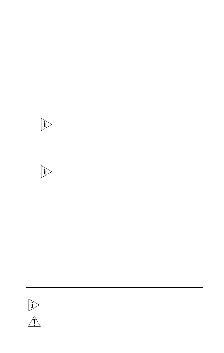
Figure 1 TokenLink Velocity XL PCI 3C359B NIC
4
16
Data
Remote
Wake-Up
connector
Page 17

16 CHAPTER 1: INTRODUCTION
High-Performance Features of the 3C359B NIC
The 3C359B NIC delivers the token ring industry’s highest
performance for the lowest cost, and is designed to provide
years of trouble-free operation. This section describes the
NIC’s high-performance features.
Parallel Tasking II Performance
The 3C359B NIC’s design incorporates new
Parallel Tasking® II performance, which takes advantage of
the latest developments in PCI bus design to deliver the
fastest data throughput and lowest CPU utilization of any
token ring NIC.
Parallel Tasking II performance is built upon a solid
foundation of proven Parallel Tasking architecture, which
introduced data pipelining and overlapping task processing
to improve throughput and achieve the industry’s fastest
data transmission and reception speeds.
DynamicAccess Class of Service
The 3Com DynamicAccess® software adds intelligence to
the 3C359B NIC for optimized performance and control.
With DynamicAccess Class of Service (T raffic Prioritization),
you can select time-critical applications that require the
highest-priority access to your network—such as
multimedia sessions. Based on your selection, the network
device driver recognizes high-priority applications,
prioritizes their data transmissions, and accelerates their
data transmissions in the following ways:
■ The NIC implements dual queues, allowing high-priority
traffic to be queued for transmission before
normal-priority traffic.
■ High-priority traffic is allowed to request and use
high-priority tokens (as specified in the IEEE 802.5
standard). This tends to reduce the latency experienced
in acquiring a suitable token for transmission onto
the network.
Class of Service (Traffic Prioritization) is available only with
the Network Driver Interface Specification (NDIS) 5.0 and
NDIS 4.0 miniport drivers supporting the following
operating systems: Windows NT 4.0 and Windows 98.
Page 18

Remote Wake-Up Support 17
Support for Full-Duplex/Dedicated Token Ring
Full-duplex/Dedicated Token Ring (DTR) is an enhancement
to the IEEE 802.5 standard that allows a token ring switch
port to be dedicated to a station.
In full-duplex mode, a station can simultaneously transmit
and receive independent data streams for potential data
throughput of 32 Mbps. The 3C359B NIC can operate in
full-duplex mode when attached to a DTR switch.
Remote Wake-Up Support
The 3C359B NIC supports the capability to remotely
wake-up a PC from a power-saving “sleep” state. The NIC
monitors the network for certain kinds of packets (such as
a Magic Packet, a directed packet, or packets that
incorporate a wake-up pattern) while the PC is asleep.
When the NIC detects a wake-up packet, it wakes up
the PC. Once the PC is awake, you can perform software
upgrades, backups, and other management tasks from a
central location.
“Remote Wake-Up” is equivalent to other popular
“wake-up” terms that are currently in use (for example,
“Wake On LAN”).
The 3C359B NIC’s Remote Wake-Up support conforms to
the Advanced Configuration and Power Interface (ACPI)
specification and applies only to PCs that implement either
the PCI Bus Power Management Interface Specification
(versions 1.0 or 1.1) or a Remote Wake-Up connector on
the PC motherboard. The connector allows a 3-wire cable
to be connected between the NIC and the motherboard.
See your PC system documentation to determine which
mechanism is supported.
If your PC supports the 3-wire cable, then install the cable
supplied with the 3C359B NIC after inserting the NIC into
the appropriate slot. (See “Connecting the Remote
Wake-Up Cable” in Chapter 2.)
If the PC has PCI bus power management, then insert the
NIC without installing the cable. No cable is required.
Page 19

18 CHAPTER 1: INTRODUCTION
After installing the NIC and attaching the Remote Wake-Up
cable (if necessary), you must configure the PC’s BIOS for
Remote Wake-Up. See your PC’s reference guide or contact
your PC vendor for instructions on accessing the BIOS.
Y our PC or server must have the following characteristics to
use Remote Wake-Up:
■ 3-pin Remote Wake-Up connector on the PC motherboard
■ BIOS that supports Remote Wake-Up
■ 5-volt standby power supply unit rated at a minimum
of 600 milliamperes
Additionally, your PC must have a desktop or network
management application capable of sending a wake-up
packet such as a Magic Packet.
If you are unsure whether your PC meets the requirements
listed described in this section, contact your PC vendor.
The NIC provides a network connection with or without the
Remote Wake-Up cable installed.
For information on installing the Remote Wake-Up cable,
see “Connecting the Remote Wake-Up Cable” in
Chapter 2.
For information on testing Remote Wake-Up, see
“Checking the Remote Wake-Up Function” in Chapter 6.
For more information on Remote Wake-Up, see the
WAKEFAQ.TXT file located in the root directory on
TokenDisk diskette 1 or in the \DISK_1 directory on the
TokenLink Velocity XL CD.
Managed PC Boot Agent (MBA)
The 3C359B NIC includes a Boot ROM socket that supports
the 3Com Managed PC Boot Agent® (MBA®), an optional
package of multiprotocol preboot firmware and tools that
is sold and documented separately.
The MBA adds management capabilities to the NIC by
enabling the PC to boot from a server, rather than from its
local drive.
This preboot support allows you to use management
applications such as ON Technology’s ON Command CCM
Page 20

Other Features of the 3C359B NIC 19
(Comprehensive Client Management), Intel Corporation’s
LANDesk Configuration Manager, and McAfee Associate’s
VirusScan to perform tasks such as:
■ Installing and configuring a new PC that has never been
connected to the network.
■ Upgrading software.
■ Scanning for viruses.
■ Performing disaster recovery tasks.
In addition to firmware, the MBA has a complete set of
tools, utilities, and Pre-OS® software that enables network
administrators to perform such tasks as:
■ Reconfiguring multiple systems at once.
■ Backing up hard drives automatically.
Other Features of the 3C359B NIC
The 3C359B NIC supports the following features:
■ Completely automatic hardware configuration through
PCI registration.
■ Auto ring speed detection option that permits the
3C359B NIC drivers for all supported environments to
detect and operate at the current ring data rate.
■ LED ring speed indicators.
■ Intelligent Auto Install software for easy installation of
NetWare 16-bit client drivers.
■ Plug and Play for worry-free installation.
■ Promiscuous mode support for Windows 95/98,
Windows NT, and Novell NetWare drivers. While
operating in this mode, the NIC receives and forwards
all network packets that arrive (regardless of the node
to which they are addressed), allowing you to easily
identify and resolve problems on the network.
■ DOS diagnostic programs to aid problem solving.
■ Full connectivity with IBM AS/400 and mainframe
computers, and compatibility with legacy IBM
applications.
■ Multicast filtering.
Page 21

20 CHAPTER 1: INTRODUCTION
■ CISPR B and FCC B certification for reduced
electromagnetic interference when using either
STP or UTP cables.
■ On-board RJ-45 and DB-9 ports for connecting UTP or
STP cables without using an external media filter.
Installation Overview
This section outlines the major steps for completing a
3C359B NIC installation. It also indicates the sections in
this guide that can help you at each stage.
Follow these steps to successfully install and configure the
3C359B NIC.
1 Insert the 3C359B NIC in a PCI bus master slot in
your PC. Connect the NIC to a compatible network
component using the appropriate cables.
See Chapter 2, “Installing the 3C359B NIC,” for detailed
instructions. Chapter 2 also provides instructions for
installing the Remote Wake-Up cable for PCs equipped to
use this feature.
2 Install the network driver that is appropriate for
your PC’s operating system environment from the
TokenDisk diskettes or from the TokenLink
Velocity XL CD.
Driver installation instructions in this guide are organized by
operating system environment. See the table of contents to
locate the chapter containing the installation instructions
appropriate for your environment.
3 Configure features that are appropriate for your
installation, if necessary. For example:
■ Auto Ring Speed Detection:
Automatically enabled for all drivers, this feature can
be disabled (recommended for servers) if necessary.
■ Class of Service:
Automatically disabled, this feature can be enabled
for the NDIS 5 and NDIS 4 drivers running under
Windows NT or Windows 98.
Page 22

Installation Overview 21
■ Locally Administered Address (LAA):
You can manually define an LAA that overrides the
NIC’s universal address encoded during manufacturing.
See feature configuration instructions in the chapter for
your operating system environment.
4 Run diagnostics, if necessary.
If you experience problems during the installation process,
you can check the configuration setup and test for physical
NIC problems by running the DOS Configuration and
Diagnostic Program, located on TokenDisk diskette 1 or in
the \DISK_1 directory on the TokenLink Velocity XL CD.
See Chapter 6, “Troubleshooting,” for instructions on
using the Configuration and Diagnostic Program. This
chapter also describes how to isolate and solve various
hardware and network cabling problems.
Page 23

Page 24

INSTALLING THE 3C359B NIC
2
This chapter describes inserting the 3C359B NIC in a PC
and connecting the PC to a network.
Installation Requirements
Installing the 3C359B NIC requires the following:
■ A PCI-bus personal computer with an 80486, Pentium,
or other Intel-compatible processor
■ A 32-bit or 64-bit PCI expansion slot that supports
bus mastering
■ A high-density 3.5-inch disk drive or CD-ROM drive
■ Category 3, 4, or 5 UTP cables, or type 1 or 6 STP cables
■ TokenDisk diskettes 1 and 2 (or TokenLink V elocity XL CD)
containing the Intelligent Auto Install program, network
driver software, the DOS Configuration and Diagnostic
Program, and online user documentation (CD only)
Safety Precautions
WARNING: PCs operate with voltages that can be lethal.
Before removing the cover, follow these steps to protect
yourself and the PC.
1 Remove any diskettes and CDs from the computer’s
disk drives.
2 Turn off the PC and unplug it.
CAUTION: To avoid permanent damage to the NIC or
other computer circuitry, always turn off the computer’s
power when inserting or removing the NIC.
3 Disconnect all cables that are connected to
the computer.
4 Remove jewelry from your hands and wrists.
Page 25

24 CHAPTER 2: INSTALLING THE 3C359B NIC
5 Reduce any static electricity on your body.
Each NIC is packed in an antistatic container to protect it
during shipment. To avoid damaging any static-sensitive
components after removal from the container, be sure to
reduce any static electricity on your body.
One way to reduce static electricity is to touch an
unpainted part of the computer’s metal chassis. You can
maintain grounding by wearing an antistatic wrist strap
attached to the chassis.
6 Verify that your tools ar e nonconducting or insulated.
Your tools should include a flat-head screwdriver and a
Phillips-head screwdriver. To avoid permanent damage to
the NIC or other computer circuitry, use only insulated or
nonconducting tools.
Unpacking and Inspecting the 3C359B NIC
Before you install the 3C359B NIC, make sure that you
have the following items:
■ TokenLink Velocity XL PCI 3C359B NIC
■ TokenDisk diskettes 1 and 2
■ TokenLink Velocity XL CD
■ Remote Wake-Up cable (optional; install this cable only
if your PC supports Remote Wake-Up and you want to
use this feature)
■ TokenLink Velocity XL PCI Network Interface Card User
Guide and Quick Guide
If any of these items are damaged or missing, contact your
shipper or network supplier.
1 Unpack the 3C359B NIC and remove it from its
antistatic container.
2 Lay the NIC on its antistatic container.
3 Inspect the NIC for visible signs of damage.
If you find damage, immediately notify your authorized
network supplier and the carrier that delivered the NIC.
Retain the original packing materials. If it is necessary to
return the 3C359B NIC to 3Com, pack it in the original (or
equivalent) packing material to maintain the warranty.
Page 26

4 If you have purchased the separate Managed PC Boot
Agent (MBA) accessory, install it in the 3C359B NIC’s
boot ROM socket according to instructions supplied
with the MBA.
To ensure the best service and support, register your 3Com
products now. U.S. customers may complete and mail the
Product Registration Card attached to this guide. All
customers may register by simply visiting the following
3Com World Wide Web site: http://www .3com/productreg.
Inserting the 3C359B NIC
Follow these steps to insert the 3C359B NIC:
1 Remove the computer’s cover and select a PCI
expansion slot that supports bus mastering.
You can install the 3C359B NIC in either a standard bus
master 32-bit slot, as shown in Figure 2 on page 26, or a
newer bus master 64-bit slot. If both slot types are available
in your PC, place the NIC in the 32-bit slot. Do not install
the NIC in a shared PCI slot.
Verify that the selected slot is a PCI bus master slot by
consulting your computer documentation, manufacturer,
or vendor. Avoid any PCI slot next to an ISA slot. This is
often a shared slot and does not support bus mastering.
Inserting the 3C359B NIC 25
Page 27
26 CHAPTER 2: INSTALLING THE 3C359B NIC
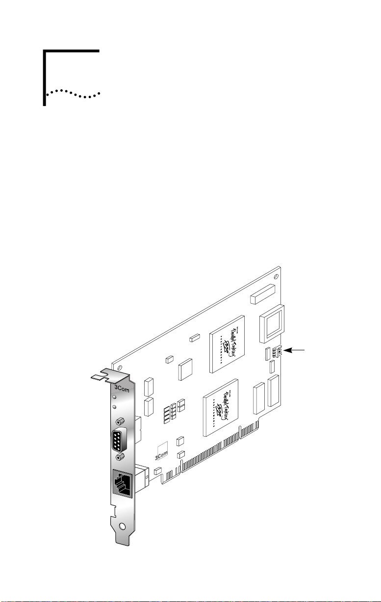
Figure 2 Removing the Expansion Slot Cover
2 Insert NIC
PCI slots
If you are planning to install the Remote Wake-Up cable,
choose an empty PCI slot that is close to the 3-pin Remote
Wake-Up connector on the PC motherboard.
2 Unfasten and remove the expansion slot cover
(Figure 2) from the selected bus master PCI slot.
Store the expansion slot cover for future use, but retain the
mounting screw for securing the NIC.
3 Insert the 3C359B NIC in an empty PCI bus master slot
and secure the mounting screw, as shown in Figure 2.
Make sure the NIC is completely seated in the slot by
pushing down firmly on both ends of the NIC. When the
NIC is correctly seated, the gold connecting fingers inserted
in the slot do not show.
Page 28

Connecting the Remote Wake-Up Cable 27
Note the slot number of the NIC. You may need it during
driver installation.
If you are installing the Remote Wake-Up cable, go to the
next section, “Connecting the Remote Wake-Up Cable,” to
continue the installation. If you are not installing the cable,
continue with step 4.
4 Replace the unit’ s cover and reconnect any cables that
you may have disconnected from other devices (see
“Safety Precautions”).
Do not turn on the power to the PC.
5 Go to “Connecting to the Network” later in this
chapter.
Connecting the Remote Wake-Up Cable
Connecting the Remote Wake-Up cable is optional.
Connect this cable only if your PC supports
Remote Wake-Up and you want to use this feature.
Your PC may conform to new PCI standards that eliminate
the need for a Remote Wake-Up cable to deliver power to
the 3C359B NIC. If your PC has PCI bus power
management, then there is no need to install the cable. See
your PC’s system documentation for complete information.
WARNING: Make sure that the PC power cord is
unplugged. Only properly trained and authorized personnel
should perform service. Contact your PC manufacturer
for information about safe service techniques.
To connect the Remote Wake-Up cable:
1 Make sure that the NIC is properly installed in a PCI slot.
2 Insert the Remote Wake-Up cable included in your
package into the connector on the NIC (see Figure 3).
3 Attach the cable to the connector on the PC
motherboard (see Figure 3).
Refer to your PC documentation if you need help with
locating the connector.
Page 29
28 CHAPTER 2: INSTALLING THE 3C359B NIC
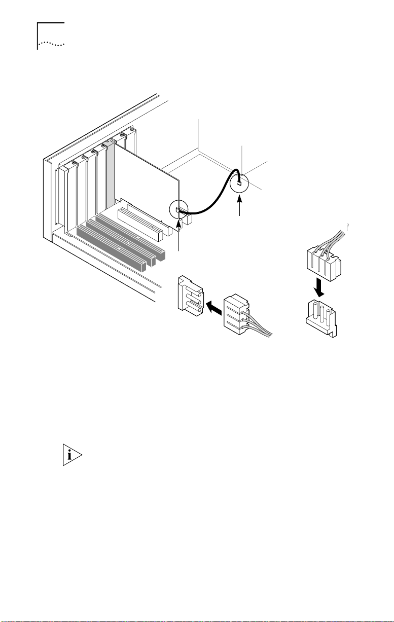
Figure 3 Connecting the Remote Wake-Up Cable
Power
supply
Plug in Remote Wake-Up
cable to connector here
Connect Remote Wake-Up
cable from NIC to motherboard connector
4 Replace the PC cover.
Do not turn on the power to the PC.
Configuring the BIOS for Remote Wake-Up
To enable Remote Wake-Up (whether you use the cable or
not), you must configure the PC’s BIOS for Remote
Wake-Up.
Do not configure the BIOS for Remote Wake-Up until you
have connected to the network and completed loading the
appropriate network driver as described later in this guide.
Your PC’s BIOS typically contains user configurable settings
for waking up the PC on Power Management Enable (PME)
or LAN signals, settings which you can usually find under
the Power or Boot categories of the BIOS. See your PC’s
reference guide or contact your PC vendor for instructions
on accessing the BIOS.
Page 30

Connecting to the Network
Follow these steps to connect the 3C359B NIC to the
network:
1 Connect one of the following network cable types to
the 3C359B NIC:
■ Shielded twisted-pair (STP) cable with a DB-9 connector
■ Unshielded twisted-pair (UTP) cable with an RJ-45
connector
The 3C359B NIC supports industry-standard token ring
Category 3, 4 or 5 UTP or types 1 or 6 STP cabling. These
cables meet IEEE 802.5 specifications. (See Appendix A,
“Specifications,” for detailed information regarding cable
requirements and connector pin assignments for the
3C359B NIC.)
2 Connect the other end of the cable to a network dual
access unit (DAU), a multistation access unit (MAU),
controlled access unit (CAU), or a token ring switch.
The 3C359B NIC can operate in full-duplex (simultaneous
send and receive) mode when attached to a Dedicated
Token Ring (DTR)-enabled switch. Operating in full-duplex
mode can optimize performance in switched environments
by doubling the available bandwidth for high-powered PC’s
and servers running mission-critical applications.
Do not turn the power on until you are ready to install the
network driver, as described in the following chapters.
When power is turned on, the PCI system automatically
configures the NIC.
Connecting to the Network 29
Page 31

Page 32

NOVELL NETWARE
3
ENVIRONMENTS
This chapter describes how to install a 3C359B NIC
network device driver for various Novell NetWare network
operating system environments.
Before you install a NetWare driver, make sure that the
3C359B NIC is inserted in the PC as described in Chapter 2.
Installing a DOS 16-Bit Client Driver
This section describes installing the DOS 16-bit client driver
using two methods:
■ Automatically, using the 3Com Intelligent Auto Install
software utility
■ Manually, using a NetWare installation utility and
TokenDisk diskette or TokenLink Velocity XL CD
Installing a DOS 16-Bit Client Automatically
The 3Com Intelligent Auto Install software utility
automatically configures one 3C359B NIC and installs the
DOS 16-bit ODI client network driver for NetWare 3.12 and
4.1x systems. This section describes running the Intelligent
Auto Install program.
Intelligent Auto Install Software Functions
Intelligent Auto Install software configures your PC as a
NetWare DOS ODI client. The Intelligent Auto Install utility
performs the following functions:
■ Installs a DOS NetWare Universal Client Virtual Loadable
Module (VLM) from TokenDisk diskette 1, or from the
TokenLink Velocity XL CD.
The Intelligent Auto Install utility cannot be used to install
multiple 3C359B NICs.
Page 33

32 CHAPTER 3: NOVELL NETWARE ENVIRONMENTS
■ Modifies the CONFIG.SYS, AUTOEXEC.BAT, and
NET.CFG files. (The previous versions of these files are
renamed CONFIG.3CM, AUTOEXEC.3CM, and
NET.3CM.)
The Intelligent Auto Install utility is a DOS application. It
cannot run in a Windows NT or Windows 95/98 DOS
window, and it cannot be used to install an OS/2,
Windows NT, or Windows 95/98 client. For these operating
systems, use the manual installation procedure described
later in this chapter.
Before Using the Intelligent Auto Install Utility
Make sure that the following steps have been performed
before using the Intelligent Auto Install utility:
■ The 3C359B NIC is installed in your DOS-based PC and
is connected to the network.
■ NetWare version 3.12 or 4.1x is installed on the server.
■ A NetWare user account is available with a user ID
and password.
■ DOS version 3.2 or later is installed on the client PC, and
the PC has been booted under DOS.
■ The PC has at least 1 MB of free hard disk space.
Modifying Intelligent Auto Install Default Settings
Use the COMSLINK.CFG file to modify the Intelligent Auto
Install process. The COMSLINK.CFG file in the \COMSLINK
directory on TokenDisk diskette 1 (or on the TokenLink
Velocity XL CD) contains default settings and descriptions
of the COMSLINK parameters.
See the COMSLINK.TXT file in the \COMSLINK directory for
information on customizing Intelligent Auto Install and
server support.
Running the Intelligent Auto Install Program
The Intelligent Auto Install program loads the NetWare
DOS ODI 16-bit client driver. To run the Intelligent Auto
Install program, follow these steps:
1 Install the 3C359B NIC and connect it to the network
as described in Chapter 2.
Page 34

Installing a DOS 16-Bit Client Driver 33
2 Restart the PC from DOS, verifying that no network
drivers are loaded.
If you are using DOS version 6.x, press F5 after the
“Starting MS-DOS...” message is displayed as DOS loads.
This prevents any drivers or memory managers from
loading. If you are using an earlier version of DOS, boot
from a DOS diskette that does not contain drivers.
3 If you are using the 3.5-inch diskettes, insert
TokenDisk diskette 1 in the drive and enter:
a:
If you are using the TokenLink Velocity XL CD, insert
it in the CD-ROM drive and enter the drive letter.
For example:
d:
4 Enter:
comslink
A COMSLINK window is displayed.
5 From the COMSLINK Information window, press
Enter.
The first time you use Intelligent Auto Install (COMSLINK),
the 3Com software license appears.
6 To accept the terms and conditions, enter:
y
To view the full text of the license agreement, press F1.
7 When the information window appears, press Enter
to continue.
A status message appears, followed by a prompt for the
ring speed of your network.
8 Enter the ring speed.
9 When the auto installation process is finished,
remove the TokenDisk diskette or TokenLink
Velocity XL CD and restart your PC.
The login prompt for a NetWare server appears.
10 Log in to the NetWare server with your ID and
password.
Your PC is now configured as a NetWare DOS ODI client.
Page 35

34 CHAPTER 3: NOVELL NETWARE ENVIRONMENTS
If you experience problems using Intelligent Auto Install,
see the next section, “Intelligent Auto Install
Troubleshooting.” If you cannot connect to the NetWare
server after running Intelligent Auto Install, see Chapter 6,
“Troubleshooting.”
Intelligent Auto Install Troubleshooting
If you experience problems when using the Intelligent Auto
Install program, display or print the COMSLINK.LOG file,
which contains a log of the events that occurred during
the Intelligent Auto Install program installation and
configuration process.
1 To display the file, enter the following DOS
command:
type comslink.log | more
2 To print the file, connect to a local printer and enter:
copy comslink.log prn
or
print comslink.log
Installing a DOS 16-Bit Client Manually
If you did not use the Intelligent Auto Install utility, follow
these steps to install the DOS 16-bit client driver for
NetWare:
1 Insert the Novell NetWare Client for DOS and
Microsoft Windows Disk 1 and make that drive the
active drive. For example, enter:
a:
2 Enter the following command:
install
Follow the displayed instructions as they appear.
3 When prompted to select the driver for your network
board, scroll down through the list titled Network
Boards. Select Other Drivers, and press Enter.
4 If you are using the 3.5-inch TokenDisk diskettes,
insert TokenDisk diskette 2 in the drive and make
that drive the active drive. For example, enter:
a:
Page 36

Installing a DOS 16-Bit Client Driver 35
If you are using the TokenLink Velocity XL CD, insert
it in the CD-ROM drive and enter the location of the
DOS 16-bit client driver:
<drive>\disk_2\netware\nwclient
5 Select 3Com TokenLink Velocity XL PCI and press
Enter.
The program copies all relevant files and makes required
changes to the AUTOEXEC.BAT and CONFIG.SYS files.
6 Copy the microcode file TLNKP.MAC to the NetWare
client directory on the hard drive.
■ If you are using the 3.5-inch TokenDisk diskettes, enter:
copy a:\tlnkp.mac c:\nwclient
■ If you are using the T okenLink V elocity XL CD, substitute
the appropriate drive and DISK_2 designation in the
path as follows:
copy d:\disk_2\tlnkp.mac c:\nwclient
7 Restart your PC to start the NetWare 16-bit client.
This completes the procedure for manually installing a
NetWare DOS 16-bit client driver.
Configuring the DOS 16-Bit Client Driver
You can edit the NET.CFG file to change the ring speed or
transmit/receive mode. Follow these steps:
1 Using a word processor or text editor, such as the
DOS Editor, open the C:\NWCLIENT\NET.CFG file.
2 Scroll through the file and locate the following lines:
LINK DRIVER TLNKPODI
3 Add the appropriate keywords as shown below.
LINK DRIVER TLNKPODI
ringspeed <auto | 4 | 16>
<classic | dtr>
where RINGSPEED AUTO forces the driver to detect the
current ring speed and to connect at that speed. The
default setting is AUTO. You do not need to specify the
AUTO setting; it is automatically enabled. If the connection
fails, try one of the other speed settings: 4 or 16. A setting
of 4 forces the driver to always open the connection at
Page 37

36 CHAPTER 3: NOVELL NETWARE ENVIRONMENTS
4 Mbps; a setting of 16 forces the driver to always open
the connection at 16 Mbps.
The keyword CLASSIC sets the transmit/receive mode to the
half-duplex Token Passing Protocol (TKP). The keyword DTR
sets the transmit/receive mode to the full-duplex Transmit
Immediate Protocol (TXI). Operating in TXI mode is
recommended; if full-duplex mode fails, try TKP mode.
Installing DOS Client32
This section describes installing the TLNKPODI.LAN DOS
Client32 driver for a NetWare Client32 environment. For
the driver installation procedure, you need the Novell
Client32 diskettes and either the TokenLink Velocity XL CD
or TokenDisk diskette 2.
1 Insert the Novell Client32 setup diskette 1 into a
drive, switch to that drive, and enter the Install
command. For example, if the diskette is in drive A,
enter:
a:\install
2 Read the Novell information window and press Enter.
The displayed window lists installation options.
3 Use the arrow keys to move to the options you need.
Press the spacebar to select the option.
The system prompts you for configuration information.
4 Confirm the configuration and press Enter.
5 If your configuration requires TCP/IP, supply the
IP Address, Router, Subnet Mask, DNS Domain, and
Domain Name Server Address. Press Enter.
6 When prompted for the LAN Driver type, select 32-bit
and press Enter.
The 32-bit Network Board Drivers window is displayed.
7 When prompted to select the driver, scroll to User
specified 32-bit driver.
8 Insert TokenDisk diskette 2 in the drive or the
TokenLink Velocity XL CD in the CD-ROM drive.
Page 38

Installing DOS Client32 37
■ If you are using the TokenDisk diskette (in Drive A for
example), enter the following path:
a:\netware\client32
■ If you are using the T okenLink V elocity XL CD (in Drive D
for example), enter the following path using the
appropriate DISK_2 designation as follows:
d:\disk_2\netware\client32
9 Select TokenLink Velocity XL PCI and press Enter.
The system allows you to change the configuration.
10 To change a parameter, select it and press Enter. Type
the new value. When you are finished changing
parameters, press Enter.
11 When the path for the configuration files is
displayed, verify that the path is correct and
press Enter.
12 Press Enter again to return to DOS and edit the
STARTNET.BAT file.
13 Add the NIC’s slot number in the STARTNET.BAT file
as follows:
load c:\novell\client32\tlnkpodi.lan
frame=token-ring msb slot=<nnnn>
where <nnnn> is the slot number.
If you do not know your NIC’s slot number, you can turn off
your PC, remove the cover, and check the slot.
14 On the same LOAD line, you can set the NIC’s ring
speed as follows.
load
c:\novell\client32\tlnkpodi.lan...ringspeed=<a
uto | 4 | 16>
where <auto | 4 | 16> is the ring speed setting:
■ Auto — Allows the NIC to automatically detect the ring
speed. (This is the default setting.)
■ 4 — Disables auto ring speed detection and sets the
NIC ring speed at 4 Mbps.
■ 16 — Disables auto ring speed detection and sets the
NIC ring speed at 16 Mbps.
Page 39

38 CHAPTER 3: NOVELL NETWARE ENVIRONMENTS
15 Restart your workstation to start Client32.
The system prompts you for the 3C359B NIC’s slot when
the TLNKPODI.LAN driver is loaded.
Installing an OS/2 Client Driver for NetWare
This section describes installing the driver for an OS/2 client.
Before installing the OS/2 ODI driver from the TokenDisk
diskette or TokenLink Velocity XL CD, ensure that the OS/2
operating system is installed and that the computer boots
without errors. Install the 3C359B NIC as described in
Chapter 2.
The Novell NetWare OS/2 ODI driver (TLNKPODI.SYS) is
available on the TokenLink Velocity XL CD or TokenDisk
diskette 1.
Selecting the Appropriate NIC Address
Before starting the OS/2 ODI client driver installation
process, you should decide whether the 3C359B NIC will
use the universal address or a locally administered address.
■ Universal address (UAA)—A default address for the
NIC. It is encoded on the NIC during manufacturing and
is often called the “burned-in” address. For example:
00600891CCA8.
■ Locally administered address (LAA)—A
user-assigned address that overrides the NIC’s universal
address. This address must consist of 12 hexadecimal
digits and must be unique throughout the network.
Check with your network administrator for the
appropriate address.
Avoid using the following sets of addresses: 40 00 xx xx xx
xx, 7F FF xx xx xx xx, C0 00 xx xx xx xx, FF FF xx xx xx xx
(where x is any hexadecimal value). Using these sets may
cause a duplicate address test (DAT) failure, or incorrect
recognition as a broadcast address.
Page 40

Installing an OS/2 Client Driver for NetWare 39
Displaying the Universal Address
The Configuration and Diagnostic Program displays the
3C359B NIC’s universal address. Follow these steps to
display the universal address:
1 Boot from a DOS diskette to run the diagnostic
program. Display the DOS prompt.
2 If you are using the 3.5-inch TokenDisk diskettes,
insert TokenDisk diskette 1 in the drive and make
that drive the active drive. For example, enter:
a:
If you are using the TokenLink Velocity XL CD (in Drive
D for example), enter the following path:
d:\disk_1
3 Enter the following command:
3pcid
The Configuration and Diagnostic Program window
is displayed as shown in Figure 4.
Figure 4 Configuration and Diagnostic Program Window
4 Record for future reference the 12-digit universal
token ring address displayed on the Diagnostic
and Configuration Program window (Figure 4).
For example:
Network Addr = 00600891CCA8
Page 41

40 CHAPTER 3: NOVELL NETWARE ENVIRONMENTS
Next, continue with the next section to install Novell OS/2
Requester and the ODI LAN driver TLNKPODI.SYS.
Installing the Novell OS/2 Requester
Follow these steps to install Novell OS/2 Requester and the
ODI LAN driver TLNKPODI.SYS:
1 Insert the Novell OS/2 Requester diskette, WSOS2_1,
in the drive.
2 At the OS/2 Full Screen prompt, make the drive
containing the diskette the active drive. For
example, enter:
a:
3 At the A: prompt, enter:
install
A NetWare Workstation for OS/2 Installation Utility
menu appears.
4 Select Installation from the menu and then Requester
on Workstation.
5 Select a target directory for the Requester files. The
default is C:\NETWARE. Select OK.
A new menu appears with four options:
■ Edit CONFIG.SYS and Copy All Files (default)
■ Only Edit CONFIG.SYS
■ Only Copy Requester Files
■ Only Copy ODI LAN Driver Files
6 From this menu, select the option Edit CONFIG.SYS
and Copy All Files and then select OK.
A dialog box appears, asking for an ODI LAN driver and
presenting two options:
■ Do not upgrade the currently installed LAN driver
■ Choose from the list or type a driver name
7 Enter the driver name for the Token V elocity XL PCI NIC:
tlnkpodi.sys
8 When prompted, select the default configuration:
IPX Support for DOS or Windows (OFF)
Page 42

Installing an OS/2 Client Driver for NetWare 41
9 Select CONTINUE.
A new menu appears with three optional protocols:
■ SPX Support for OS/2 Sessions
■ NetBIOS Emulation for OS/2 Sessions
■ Remote Named Pipe Support
10 Select the appropriate protocol and save the
configuration.
If no additional protocols are needed, do not select any
of the three options. Bypass this section by choosing Save
the configuration.
A new menu appears, asking if you want to save changes
to the CONFIG.SYS file.
11 Save the file as C:\CONFIG.SYS and click OK
to continue.
A new window appears, confirming that you want all files
copied to C:\NETWARE.
12 Click COPY and follow the displayed instructions.
Continue the installation and insert the appropriate OS/2
Requester diskettes when prompted.
After the OS/2 Utility diskette is installed, a window
appears that requests information about the ODI LAN
drivers. The default ODI LAN driver is TLNKPODI.SYS.
13 Insert TokenDisk diskette 1 or the TokenLink
Velocity XL CD in the appropriate drive.
14 Select Copy Only the Default Driver and click OK.
If you inserted the T okenLink V elocity XL CD at step 13, you
must specify the location of TLNKPODI.SYS as follows:
d:\disk_1
15 Follow the displayed installation instructions and
insert the appropriate OS/2 Requester diskettes
when prompted.
When the installation is complete, a menu appears with the
following menu bar items:
■ Installation
■ Configuration
■ Utilities
Page 43

42 CHAPTER 3: NOVELL NETWARE ENVIRONMENTS
■ Readme
■ Help
A message is displayed, stating that the installation process
is complete. Follow the instructions, and continue with
configuration steps in the following section.
Configuring the Novell OS/2 Requester
When you have followed the displayed instructions at
the end of the Novell OS/2 Requester installation process,
a message appears concerning certain configuration
requirements.
After reading the message regarding configuration
requirements, follow these steps:
1 Click the Configuration menu bar item and select
“This Workstation...” to check the NET.CFG file for
the proper NIC configuration.
2 Verify the link driver header, node address, and
frame type.
Your NET.CFG file should look similar to the following:
LINK DRIVER TLNKPODI
Node Address 00608C112233
Frame Token-Ring MSB
Frame Token-Ring_SNAP MSB
The node address should be set to the UAA or the LAA.
Modify and save the NET.CFG file if the node address and
frame type are not correct.
3 Remove the OS/2 Requester diskette and restart
the PC.
This completes the procedure for installing the OS/2 client
driver for NetWare.
Installing a NetWare Server Driver
This section contains information about installing the
TLNKPODI.LAN NetWare server driver for the 3C359B NIC
in the following environments:
■ NetWare 3.12
■ NetWare 4.1x
■ NetWare 5.0
Page 44

The driver and associated files are located in the
\NETWARE\NWSERVER directory on TokenDisk diskette 2,
or in the \DISK_2\NETWARE\NWSERVER directory on the
TokenLink Velocity XL CD.
Driver Support
The TLNKPODI server driver is a high-performance
NetWare 4.1x-compliant server driver. It can be used in
the following environments:
■ NetWare 5.0 servers
■ NetWare 4.1x servers
■ NetWare 3.12 servers
■ NetWare servers running SFT III in NetWare 4.1 (as an
The term “NetWare 4.1x-compliant” server driver in this file
means that the HSM (hardware-specific module, or server
driver) meets the Open Data-Link Interface (ODI) 3.3
specification. Netware 3.12 servers using ODI 3.3 drivers
need updated files from Novell. If you are installing the
driver in a NetWare 3.12 server, download the LANDR9
and 312PTA.EXE files from Novell’s Web site.
Installing a NetWare Server Driver 43
IPX link, not as a mirrored server link)
Installation Instructions
This section has instructions for installing TLNKPODI in
three ways:
■ On a file server in an existing NetWare environment
running NetWare 3.12 or 4.1x. These instructions also
apply to a new installation or upgrade to NetWare 3.12.
■ As part of a new NetWare 4.1x installation or an
upgrade to NetWare 4.1x.
■ As part of an upgrade to NetWare 5.0.
Instructions in this section are written for TokenDisk
diskettes. If you are using the TokenLink Velocity XL CD,
substitute the appropriate path (using the \DISK_2
designation at the start of the path) where required.
Page 45

44 CHAPTER 3: NOVELL NETWARE ENVIRONMENTS
Installing the Driver in an Existing
NetWare Environment
This section explains how to install TLNKPODI on a file
server already running NetWare 3.12 or 4.1x. The
instructions in this section should also be used for a new
NetWare 3.12 installation or an upgrade to NetWare 3.12.
If you are in the process of upgrading to NetWare 4.1x,
proceed to “Installing the Driver as Part of a New Server
Installation or Upgrade to NetWare 4.1x.”
If you are in the process of upgrading to NetWare 5.0,
proceed to “Installing the Driver as an Upgrade to
NetWare 5.0.”
TokenDisk diskette 2 contains the server driver and versions
of Novell NetWare Loadable Modules (NLMs) required for
all NetWare 4.1x-compliant server drivers. You must use
these NLMs, or more recent versions, with TLNKPODI.
Table 3 shows the names, locations, and versions of the
support modules.
Table 3 Location of NetWare Support Modules
NetWare
Version
4.1x or 5.0 \NETWARE\NWSERVER\41x_5.0\MSM.NLM
3.12 \NETWARE\NWSERVER\3.12\MSM31X.NLM
Directory
\NETWARE\NWSERVER\41x_5.0\NBI.NLM
\NETWARE\NWSERVER\41x_5.0\TLNKPODI.INF
\NETWARE\NWSERVER\41x_5.0\TLNKPODI.LAN
\NETWARE\NWSERVER\41x_5.0\TLNKPODI.LDI
\NETWARE\NWSERVER\41x_5.0\TOKENTSM.NLM
\NETWARE\NWSERVER\3.12\NBI31X.NLM
\NETWARE\NWSERVER\3.12\TLNKPODI.LAN
\NETWARE\NWSERVER\3.12\TOKENTSM.NLM
Deciding If Modules Need to Be Replaced At the
server command prompt, enter MODULES. The resulting
display shows what drivers and modules are currently
running on the server . Locate the entries for MSM.NLM and
TOKENTSM.NLM. (MSM31X.NLM appears as MSM.NLM.)
If any of the versions currently running is earlier than 2.50,
you must replace modules MSM31X.NLM, MSM.NLM, or
TOKENTSM.NLM.
Page 46

Installing a NetWare Server Driver 45
The modules on TokenDisk diskette 2 (or in the \DISK_2
directory on the TokenLink Velocity CD) are version 2.50.
You can load the server driver as described later in this
chapter in “Using the LOAD Command.”
CAUTION: Using versions of MSM.NLM, MSM31X.NLM,
and TOKENTSM.NLM earlier than 2.50 with TLNKPODI.LAN
prevents the driver from loading.
Replacing Support Modules To replace support
modules with more recent versions, use the steps below
to load the support modules from the TokenDisk diskette
and copy them to the file server.
Instructions in this section are written for TokenDisk
diskettes. If you are using the TokenLink Velocity XL CD,
substitute the appropriate path (using the \DISK_2
designation at the start of the path) where required.
1 Use the Unload command from the console command
prompt to unload any existing server drivers that
depend on the support modules you need to replace.
This command will completely unload the drivers from
memory and will terminate communication with currently
attached network users.
The format of the command is:
unload <driver_name>
2 Unload the support modules by entering the
commands in the order shown below:
unload tokentsm
unload msm
3 Load the support modules from TokenDisk diskette 2.
Enter the following commands when the diskette is
in drive A. Use a different drive if necessary:
NetWare 4.1x and 5.0 servers:
load a:\netware\nwserver\41x_5.0\nbi
load a:\netware\nwserver\41x_5.0\msm
load a:\netware\nwserver\41x_5.0\tokentsm
NetWare 3.12 servers:
load a:\netware\nwserver\3.12\nbi31x
load a:\netware\nwserver\3.12\msm31x
load a:\netware\nwserver\3.12\tokentsm
load a:\netware\nwserver\3.12\monitor
Page 47

46 CHAPTER 3: NOVELL NETWARE ENVIRONMENTS
Copying Support Modules and the Driver to the
File Server This section explains how to copy support
modules and TLNKPODI.LAN to the file server. If you have
replaced existing support modules, follow this procedure,
so that the most current versions of the support modules
load whenever you load a server driver.
The SYS volume on the file server must be mounted, you
must have rights to copy files to the SYS:SYSTEM directory,
and at least one server driver must be loaded and bound to
a protocol.
Instructions in this section are written for TokenDisk
diskettes. If you are using the TokenLink Velocity XL CD,
substitute the appropriate path (using the \DISK_2
designation at the start of the path) where required.
1 Locate a workstation with a diskette drive. This
workstation must allow you to log in to the file
server to which you will copy the NLMs.
2 Log in to the file server . Insert TokenDisk diskette 2 in
the drive and copy the support files to the server.
If drive F is mapped to the SYS volume, the sample
commands shown below copy files from a diskette in the
workstation’s drive A to a NetWare 4.1x file server:
copy a:\netware\nwserver\41x_5.0\msm.nlm
f:\system
copy a:\netware\nwserver\41x_5.0\tokentsm.nlm
f:\system
3 Enter the following command to copy the
TLNKPODI.LAN server driver to F:SYS:SYSTEM:
copy a:\netware\nwserver\41x_5.0\tlnkpodi.lan
f:\system
Using the LOAD Command You can enter the LOAD
command from the server's console command prompt or
you can include it in your AUTOEXEC.NCF file to load the
driver automatically when you start the SERVER program.
The format of the command is shown below:
load <path>\tlnkpodi <parameter_list>
where <path> is the full pathname to the location of
TLNKPODI.LAN, if it is not at SYS:SYSTEM.
Page 48

Each LOAD command must be entered on a separate,
single line.
Table 4 summarizes the Load parameters that can be used
with TLNKPODI.LAN. Detailed descriptions of the
parameters begin after the table.
Table 4 TLNKPODI.LAN Load Parameters
Installing a NetWare Server Driver 47
Parameter Units
SLOT= Decimal Value assigned
FRAME= Text TOKEN-RING Specifies the frame types supported
NODE= Hex See detailed
NAME= Any N/A Sets the optional logical board name
Supported
Values
by PCI BIOS
description in
text.
Description
Sets the slot number prompts.
on the network.
Default = TOKEN-RING
Overrides the default node ID.
Default = stored on board the NIC
(17 characters maximum).
Default = absent
SLOT=<value> Required if there is more than one
3C359B NIC installed in the server; you will be prompted to
supply a value if you do not enter one. This parameter
specifies the slot number for the NIC. The slot number is
automatically assigned by the PCI BIOS.
There are two ways you can supply a slot number for the NIC:
■ Enter a value when prompted by the server.
■ Manually find the slot number by loading the driver
as described later in this chapter in “Finding the Slot
Number Manually.”
Regardless of the method you choose, you must supply
a slot number for each 3C359B NIC installed in the server.
Once you have noted the slot number of each NIC, you can
include the LOAD and BIND commands in the server’s
AUTOEXEC.NCF file so the driver will be automatically
loaded when you start the SERVER program.
After a server driver has been loaded, you can view the
configuration of each driver (including LOAD command
Page 49

48 CHAPTER 3: NOVELL NETWARE ENVIRONMENTS
parameters) using the CONFIG command from the server
console command prompt.
At system boot, the PCI BIOS determines slot numbers for
all PCI NICs. Adding or removing PCI NICs can cause the slot
numbers of all other PCI NICs to change. Therefore, after
adding or removing PCI NICs in your machine, you should
verify the slot numbers used by all PCI NICs (including the
3C359B NIC) and change the LOAD command SLOT=
parameters for them accordingly.
FRAME=<type> Specifies the frame type used by this
logical board. (A “logical board” means a particular
instance of loading the server driver.)
You do not need to include this parameter if you will be
using only the default frame type, TOKEN-RING. But you
must make sure the server driver is configured for all frame
types used on the network.
If you want to use both frame types, you must load the
driver twice, as shown below:
load tlknpodi slot=<value> frame=token-ring
load tlknpodi slot=<value>
frame=token-ring_snap
NODE=<node-ID> Specifies that the locally
administered node ID parameter overrides the default
globally administered node ID stored on the NIC. The node
IP is a hexadecimal number in the range of locally
administered node IDs permitted under IEEE guidelines. The
node address you select must be unique. For example:
node=4000123AB678
Check with your network administrator for the appropriate
address.
Avoid using the following sets of addresses: 40 00 xx xx xx
xx, 7F FF xx xx xx xx, C0 00 xx xx xx xx, FF FF xx xx xx xx
(where x is any hexadecimal value). Using these sets may
cause a duplicate address test (DAT) failure, or incorrect
recognition as a broadcast address.
Page 50

Installing a NetWare Server Driver 49
NAME=<name> An optional name for identifying this
logical board. NAME is commonly used when you bind
a protocol to the driver. This parameter is limited to 17
alphanumeric characters and must be unique among all
logical boards in the file server.
Finding the Slot Number Manually This section shows
how to manually determine the slot numbers of two
3C359B NICs installed in a file server. You do not need to
take these actions if you want to enter the slot numbers
when prompted by the server.
The samples below show the server console display when
two 3C359B NICs are installed.
This is the LOAD/BIND sequence for the first of two NICs:
FS1:load c:tlnkpodi
Loading module tlnkpodi.lan
3Com TokenLink PCI Server MLID
Version 1.00c [date]
(C) Copyright 1993-97, 3Com Corp. All
rights reserved
Supported slot values are 1,2
Slot: 1
Data Rate = 16 Mbps.
Max Packet Size = 17954
IO Address Base = F480
Memory Basic Address = FF9EFE800
IRQ = 10
Number of transmit buffers (DPDs) configured = 5.
Number of receive buffers (UPDs) configured = 3.
MicroCode Version String = 01.20 10/20/97
The supported slot values shown are for the two 3C359B
NICs in the server. The next line is where you enter the
address that you will use.
This is the LOAD/BIND sequence for the second of two
NICs:
FS1:load c:tlnkpodi
Do you want to add another frame type for a
previously loaded board? n
Supported slot values are 4
Slot: 4
Data Rate = 16 Mbps.
Page 51

50 CHAPTER 3: NOVELL NETWARE ENVIRONMENTS
Max Packet Size = 17954
IO Address Base = EC80
Memory Basic Address = FFDFFC00
IRQ = 11
Select board to bind:2
IPX LAN protocol bound to 3Com 3Com TokenLink
PCI Server MLID FS1:
Once you have determined the values for the NICs installed
in the server, you can use the SLOT= parameter to load the
driver either from the command line or by placing the
LOAD command in the AUTOEXEC.NCF file to load
automatically each time the server is started.
Using the BIND Command After loading the driver,
use the BIND command to bind each NIC to a protocol.
Enter the command from the server console command
prompt, or include the command in the AUTOEXEC.NCF
file to automatically bind the driver when you start the
SERVER program.
bind {ipx | ip} [to] <name | drivername>
{net=<number> | addr=<number>}
IPX | IP The name of the protocol to which you are
binding the driver (IPX or IP). If you specify IP, other
parameters are required; consult your TCP/IP
documentation for more information.
NAME (Optional.) The name you assigned to the logical
board with the Load command. If you use a logical board
name, do not specify DRIVERNAME.
DRIVERNAME The name of the driver you are using. Do
not use DRIVERNAME if you assigned a logical board name
with the NAME parameter.
NET=<number> (IPX protocol only.) The unique IPX
internal network number you have assigned to this
network. It is a hexadecimal number up to eight
characters long. For example:
net=5A
Page 52

Installing a NetWare Server Driver 51
ADDR=<number> (TCP/IP protocol only.) The NIC’s
network address. The address must be unique on the
internetwork. For example:
addr=192.45.67.8
To view the current configuration, enter the CONFIG
command at the server’s console command prompt.
Installing the Driver as Part of a New Server Installation or Upgrade to NetWare 4.1x
This section has instructions for loading TLNKPODI.LAN as
part of a new NetWare server installation or an upgrade to
NetWare 4.1x. The procedure shows the essential steps for
installing the server driver only . For most installations, other
steps will be required; consult your Novell documentation
for information about any procedures not described below.
Instructions in this section are written for TokenDisk
diskettes. If you are using the TokenLink Velocity XL CD,
substitute the appropriate path (using the \DISK_2
designation at the start of the path) where required.
1 At the Load LAN Driver menu, insert TokenDisk
diskette 2 into the drive and press Alt+Esc to switch
from the Install program to the server console
command prompt.
2 Enter the following commands at the server console
command prompt:
unload tokentsm
unload msm
3 From TokenDisk diskette 2, load the support modules
required to run the server driver. Enter the following
commands at the server console command prompt in
the order shown:
load a:\netware\nwserver\41x_5.0\nbi
load a:\netware\nwserver\41x_5.0\msm
load a:\netware\nwserver\41x_5.0\tokentsm
Typically, the modules that ship with NetWare 4.1x are an
earlier version than 2.50. It is recommended that you use
MSM.NLM and TOKENTSM.NLM version 2.50 or later with
TLNKPODI.LAN.
Page 53

52 CHAPTER 3: NOVELL NETWARE ENVIRONMENTS
4 Press Alt+Esc to return to the Install program.
5 Press Insert to load an unlisted LAN driver, and then
follow the prompts to specify the driver load path.
6 At the next menu, enter the following path:
a:\netware\nwserver\41x_5.0
After a short delay, a menu appears, showing the
TLNKPODI.LAN driver.
7 Press Enter to select the TLNKPODI.LAN driver.
8 When asked if you want to copy the driver (to
SYS:SYSTEM), respond Yes.
The next menu shows the parameters that can be used
with the 3C359B token ring NIC driver.
9 Press Enter to view a list of supported options for the
selected parameter.
Additional help for the parameter is also displayed in the
lower text box. You can also find a description of
parameters and explanations earlier in this chapter in
“Using the LOAD Command.”
10 After you have made selections for all 3C359B NIC
driver parameters, press F10 to save the parameters
and load TLNKPODI.LAN. Then follow the prompts to
complete the server installation.
11 After completing the installation, copy the support
modules MSM.NLM and TOKENTSM.NLM from
TokenDisk diskette 2 to the server’s SYS:SYSTEM
directory.
Doing so causes the support modules to be auto-loaded
by any of the server drivers, such as TLNKPODI.LAN. See
“Copying Support Modules and the Driver to the
File Server” earlier in this chapter for instructions.
Installing the Driver as an Upgrade to NetWare 5.0
This section has instructions for loading TLNKPODI.LAN as
part of an upgrade to NetWare 5.0. The procedure shows
the essential steps for upgrading the server driver only. For
most upgrades, other steps will be required; consult your
Novell documentation for information about any
procedures not described below.
Page 54

Installing a NetWare Server Driver 53
Instructions in this section are written for TokenDisk
diskettes. If you are using the TokenLink Velocity XL CD,
substitute the appropriate path (using the \DISK_2
designation at the start of the path) where required.
1 At the Load LAN Driver menu, insert TokenDisk
diskette 2 into the drive.
2 Press Insert to load an unlisted LAN driver, and then
follow the prompts to specify the driver load path.
3 At the next menu, enter the following path:
a:\netware\nwserver\41x_5.0
After a short delay, a menu appears, showing the
TLNKPODI.LAN driver.
4 Press Enter to select the TLNKPODI.LAN driver.
5 When asked if you want to copy the driver (to
SYS:SYSTEM), respond Yes.
The next menu shows the parameters that can be used
with the 3C359B token ring NIC driver.
6 Press Enter to view a list of supported options for the
selected parameter.
Additional help for the parameter is also displayed in the
lower text box. You can also find a description of
parameters and explanations earlier in this chapter in
“Using the LOAD Command.”
7 After you have made selections for all 3C359B NIC
driver parameters, press F10 to save the parameters
and load TLNKPODI.LAN. Then follow the prompts to
complete the server installation.
UNBIND and UNLOAD Commands
Y ou can use the UNBIND or UNLOAD commands to r emove
a driver (or logical board). The commands have the format
shown below:
unbind ipx tlnkpodi <name>
unload tlnkpodi
The UNBIND command requires only that you reenter
the BIND command, and does not affect the LOAD
command. You can selectively unbind a protocol for a
Page 55

54 CHAPTER 3: NOVELL NETWARE ENVIRONMENTS
particular logical board by specifying a board name, as
shown in the command sample.
The UNLOAD command completely unloads the driver from
memory. If you wish to reload the driver, you will be
required to use the LOAD and BIND commands.
Page 56

MICROSOFT WINDOWS
4
ENVIRONMENT
This chapter describes how to install a 3C359B NIC
network device driver for various Microsoft Windows
environments.
Drivers Available for Windows
3Com provides the following network device drivers for the
3C359B NIC in these Microsoft Windows environments:
■ Network Driver Interface Specification (NDIS) 5 miniport
driver
■ NDIS 4 miniport driver
■ NDIS 3 miniport driver
NDIS 5 Miniport Driver
The NDIS 5 driver conforms to Microsoft’s latest NDIS 5.0
miniport specification and supports the following Windows
environments:
■ Windows 98
■ Windows 2000
The NDIS 5 driver provides the following 3C359B NIC
capabilities:
■ DynamicAccess Class of Service (Traffic Prioritization)
■ Auto ring speed detection
■ Promiscuous mode
■ Locally administered network address (LAA) selection
Class of Service is disabled by default. You can enable this
DynamicAccess feature during installation.
Auto ring speed detection is enabled by default during
NDIS 5 driver installation. You can disable this feature
during installation if desired.
Page 57

56 CHAPTER 4: MICROSOFT WINDOWS ENVIRONMENT
Promiscuous mode is automatically enabled and controlled
for the 3C359B NIC by applications that require this
feature. No user control is necessary.
You can assign a locally administered address (LAA) that
overrides the NIC’s universal address “burned-in” during
manufacturing.
NDIS 4 Miniport Driver
The NDIS 4 driver conforms to Microsoft’s NDIS 4.0
miniport specification and supports the following Windows
environments:
■ Windows 95 (version 950b, OSR2)
■ Windows 98
■ Windows NT 4.0
The NDIS 4 driver supports all the 3C359B NIC features
listed in the preceding section for the NDIS 5 driver.
NDIS 3 Miniport Driver
The NDIS 3 miniport driver is compatible with Microsoft’s
NDIS 3.x miniport specification, and supports the following
Windows environments:
■ Windows 95 (version 950 and version 950b, OSR2)
■ Windows NT 3.51
The NDIS 3 driver supports all the 3C359B NIC features
listed in the preceding section for the NDIS 5 and NDIS 4
drivers except DynamicAccess Class of Service.
Installing a 3C359B NIC Driver for Windows Environments
This section describes installing drivers for the following
operating system environments:
■ Windows 98
■ Windows 95 version 950
■ Windows 95 version 950b (OSR2)
■ Windows NT 4.0
■ Windows NT 3.51
Page 58

Installing a 3C359B NIC Driver for Windows Environments 57
Before Installing a Windows Driver
Before you install a Windows driver, make sure that the
3C359B NIC is inserted in the PC as described in Chapter 2,
and that Windows is installed.
Have the Windows software accessible on diskettes, CD, or
hard drive in case the installation utility requests protocol
files from the Windows software library.
If your network environment uses the TCP/IP
communications protocol, you must obtain from your
network administrator all the information you will need
to define an IP address during the installation process.
3Com recommends that you use the NetBEUI or TCP/IP
protocol stacks when installing the 3C359B NIC in a
Windows 95 client attaching to a Windows NT server.
Installing a Driver for Windows 98
To install the network driver in a PC running Windows 98:
1 Make sure that the NIC is installed in your PC and that it
is connected to the network, as described in Chapter 2.
2 Turn on the power to the PC.
Windows 98 detects the NIC. The Add New Hardware
Wizard (Figure 5) starts.
Figure 5 Add New Hardware Wizard
Page 59

58 CHAPTER 4: MICROSOFT WINDOWS ENVIRONMENT
3 If you are using the 3.5-inch diskettes, insert
TokenDisk diskette 1 in the drive, and then click Next.
If you are using the TokenLink Velocity CD, insert it in
the CD-ROM drive, and then click Next.
4 Select Search for the best driver for your device
(Recommended), and then click Next.
5 If you are using the 3.5-inch diskettes, select Floppy
disk drives, and then click Next. If you are using the
TokenLink Velocity CD, select CD-ROM drives, and
then click Next.
Windows finds the driver file for the device.
6 Click Next.
Files are copied.
If the Insert Disk window appears, prompting you to insert
the TokenDisk diskette, click OK.
You’re prompted for the Windows 98 CD.
7 Insert the Windows 98 CD in the CD-ROM drive, and
then click OK.
If you don’t have the Windows 98 CD, click OK. Enter the
path for the Windows 98 installation files on your PC in the
Copying Files entry box.
Files are copied. The installation is complete when you’re
prompted to click Finish.
8 Click Finish.
You’re prompted to restart the PC.
9 Click Yes to restart the PC.
You must reboot your PC to complete the installation.
The driver installation for Windows 98 is complete. To
confirm successful installation, see “Verifying Successful
Installation” on page 65.
To disable auto ring speed detection and manually select
the ring speed, see “Setting Ring Speed for
Windows 95/98” on page 66 for more details.
To define a locally administered network address, see
“Defining the LAA Address for Windows 95/98” on
page 72 for more details.
Page 60

Installing a 3C359B NIC Driver for Windows Environments 59
To select applications for high-priority network access, see
“Configuring Class of Service” on page 78 for more details.
Installing a Driver for Windows 95
This section describes installing the 3C359B NIC NDIS 4
driver or NDIS 3 driver for the following Microsoft
Windows 95 versions:
■ Version 950 (950a, or “retail” version)
■ Version 950b (OEM Service Release 2, or OSR2)
About Microsoft Windows 95 Versions
The 3C359B NIC NDIS 4 driver installation procedures differ
depending on the Windows 95 version installed on your PC.
Version 950 of Windows 95 If your PC did not come
with Windows 95 already installed, you must install
version 950 of Windows 95 (950a, or “retail” version)
before you install the driver. Version 950 of Windows 95
is designed to upgrade Windows 3.x PCs.
Version 950b (OSR2) of Windows 95 Some PCs are
sold with a special Windows 95 version already installed.
Windows 95 OEM Service Release 2 (OSR2) is version 950b
of Windows 95. An OEM Service Release is an updated
version of a Microsoft product for PC original equipment
manufacturers (OEMs) to preinstall on new PCs. Windows 95
version 950b contains some new hardware support
and programs.
Finding the Windows 95 Version To determine which
Windows 95 version you are using, open the Control Panel,
select System, and read the System information under
the General tab. If your release is version 4.00.950 (or
4.00.950a), you are using the “retail” version of Windows 95
(version 950). If your release is version 4.00.950b, you are
using the OSR2 version of Windows 95 (version 950b).
Page 61

60 CHAPTER 4: MICROSOFT WINDOWS ENVIRONMENT
Installing a Driver for Windows 95 Version 950
Follow these steps to install the NDIS 3 driver for
Windows 95 (version 950). It is assumed that you have
completed the 3C359B NIC installation procedure
described in Chapter 2.
1 Turn on the computer and start Windows 95.
Windows 95 automatically detects the new hardware in
the PC. Windows 95 displays the New Hardware Found
window.
2 Select Driver from disk provided by hardware
manufacturer and click OK.
Windows 95 displays the Install from Disk dialog box,
which prompts you to insert the appropriate disk and
to enter the directory location for the NDIS 3 driver.
3 If you are using the 3.5-inch diskettes, insert
TokenDisk diskette 2 in the drive. If you are using the
TokenLink Velocity XL CD, insert it in the CD-ROM
drive.
4 At the prompt, enter the appropriate path for the
drive containing your TokenDisk diskette or
TokenLink Velocity XL CD and the NDIS 3 driver.
■ If you are using the 3.5-inch TokenDisk diskettes, enter:
a:
■ If you are using the T okenLink V elocity XL CD, substitute
the appropriate drive (drive D, for example) and the
DISK_2 designation in the path as follows:
d:\disk_2
5 Click OK.
If Windows 95 prompts you to insert the Windows 95 CD
or diskettes to obtain files from the Windows 95 software
library, insert the appropriate diskette or CD and continue
as directed by the prompts.
6 When the setup file has been read, select
TokenLink Velocity XL PCI Adapter on the list and
click OK.
Windows 95 imports the driver, and the driver installation
is complete.
Page 62

Installing a 3C359B NIC Driver for Windows Environments 61
7 Remove the TokenDisk diskette or TokenLink
Velocity XL CD and restart your computer.
This concludes the procedure for installing the NDIS 3
driver for Windows 95 (version 950). To confirm successful
installation, see “Verifying Successful Installation” on
page 65.
Installing a Driver for Windows 95 Version 950b, OSR2
Follow these steps to install the driver for Windows 95
version 950b, OSR2. It is assumed that you are already
running Windows 95.
During installation, have the Windows 95 software
accessible on diskettes, CD, or hard drive in case the
installation utility requests files from the Windows 95
software library.
1 Install the 3C359B NIC and start the computer.
Windows 95 detects the new hardware. PCI Token Ring
Controller appears in the New Hardware Found dialog
notice. The Update Device Driver Wizard dialog
box appears.
2 Click Next.
3 Click Other Locations.
The Select Other Location dialog box appears.
4 If you are using 3.5-inch diskettes, insert TokenDisk
diskette 2 in the drive. If you are using the TokenLink
Velocity XL CD, insert it in the CD-ROM drive.
5 At the prompt, enter the appropriate path for the
drive containing your TokenDisk diskette or
TokenLink Velocity XL CD and the driver you want to
install.
■ Use the following path to install the NDIS 4 driver
(recommended) from the TokenDisk diskette:
a:
■ If you are using the T okenLink V elocity XL CD, substitute
the appropriate drive (drive D, for example) and the
DISK_2 designation in the path as follows:
d:\disk_2
Page 63

62 CHAPTER 4: MICROSOFT WINDOWS ENVIRONMENT
6 Verify that the Update Device Driver Wizard dialog
box lists 3Com T okenLink Velocity XL PCI Adapter, and
click Finish.
Have the Windows 95 software accessible in case the
installation utility requests files from the Windows 95
software library. Insert the appropriate diskette or CD if
prompted to do so.
Messages appear while files are being copied. The System
Settings Change dialog box appears.
7 Remove the TokenDisk diskette or TokenLink
Velocity XL CD from the drive.
8 Click Yes to restart the computer.
This concludes the procedure for installing a driver for
Windows 95 version 950b, OSR2. To confirm successful
installation, see “Verifying Successful Installation” on
page 65.
To disable auto ring speed detection and manually select
the ring speed, see “Setting Ring Speed for
Windows 95/98” on page 66 for more details.
To define a locally administered network address, see
“Defining the LAA Address for Windows 95/98” on
page 72 for more details.
Installing a Driver for Windows NT 4.0
Follow these steps to install the 3Com NDIS 5 or NDIS 4
driver for Windows NT 4.0.
If your network environment uses the TCP/IP
communications protocol, obtain from your network
administrator all the information you need to define an
IP address during the installation process before starting.
1 In the My Computer group, double-click the
Control Panel icon.
2 In the Control Panel group, double-click the
Network icon.
3 In the Network dialog box, click the Adapters tab.
4 In the Adapters tab, click Add.
Page 64

Installing a 3C359B NIC Driver for Windows Environments 63
5 In the Select Network Adapter dialog box, click
Have Disk.
The Insert Disk dialog box appears.
6 If you are using the 3.5-inch diskettes, insert
TokenDisk diskette 2 in the drive. If you are using the
TokenLink Velocity XL CD, insert it in the CD-ROM
drive.
7 Accept the displayed default path by clicking OK.
For example, if you are using the 3.5-inch diskettes, the
following path is displayed:
a:
This path identifies the location of the driver files
for Windows NT 4.0. The Select OEM Option dialog
box appears.
8 Select 3Com TokenLink Velocity XL PCI Adapter and
click OK.
9 Verify that 3Com TokenLink Velocity XL PCI Adapter
appears in the list in the Network Adapters tab and
click Close.
If your network environment uses the TCP/IP
communications protocol, the Microsoft TCP/IP Properties
dialog box is displayed. You must obtain from your
network administrator all the information you need to
define an IP address during the installation process.
Continue after you have defined the NIC for TCP/IP.
Bindings messages appear, followed by a prompt to restart
the computer.
10 Remove the TokenDisk diskette or TokenLink
Velocity XL CD from the drive.
11 Click Yes to restart the computer.
This concludes the procedure for installing the driver for
Windows NT 4.0. To confirm successful installation, see
“Verifying Successful Installation” on page 65.
To disable auto ring speed detection and manually select
the ring speed, see “Setting Ring Speed for Windows NT
4.0” on page 70 for more details.
Page 65

64 CHAPTER 4: MICROSOFT WINDOWS ENVIRONMENT
To define a locally administered network address, see
“Defining the LAA Address for Windows NT” on page 76
for more details.
To select applications for high-priority network access, see
“Configuring Class of Service” on page 78 for more details.
Installing a Driver for Windows NT 3.51
Follow these steps to install the NDIS 3 driver for
Windows NT 3.51.
1 If you are using the 3.5-inch diskettes, insert
TokenDisk diskette 2 in the drive. If you are using the
TokenLink Velocity XL CD, insert it in the CD-ROM
drive.
2 In the Main group, double-click the Control Panel
icon.
3 In the Control Panel group, double-click the
Network icon.
4 In the Network Settings dialog box, click
Add Adapter.
5 In the Add Network Adapter dialog box, scroll to the
bottom of the Network Adapter Card selection list.
Select <Other> Requires disk from manufacturer.
6 Click Continue.
7 Accept the displayed default path by clicking OK to
select the NIC.
For example, if you are using the 3.5-inch diskettes, the
following path is displayed:
a:\
This path identifies the location of the NDIS 3 driver files for
Windows NT 3.51.
The driver files are copied to the C drive. A prompt
appears, asking if you want to restart your computer.
8 Remove the TokenDisk diskette or TokenLink
Velocity XL CD and click Restart now.
This concludes the procedure for installing the NDIS 3
driver for Windows NT 3.51. To confirm successful
Page 66

Verifying Successful Installation 65
installation, see the next section, “Verifying Successful
Installation.”
Verifying Successful Installation
To confirm that the NIC is installed correctly in your PC,
follow the steps appropriate for your operating system.
Windows 95 and Windows 98
To confirm that the NIC is installed correctly in a PC running
Windows 95 or Windows 98:
1 Right-click the My Computer icon, click Properties,
and then select the Device Manager tab.
A list of devices appears on the Device Manager screen,
arranged by type.
2 Double-click Network adapters.
The name of the installed 3C359B NIC appears on the
Device Manager screen.
If a yellow exclamation point (!) or a red X appears next
to the NIC name, the installation wasn’t successful. See
Chapter 6, “Troubleshooting,” for more information.
3 Double-click the name of the NIC to display a
description of the NIC and its current status.
The message in the Device status panel confirms that the
NIC is working properly.
4 Click Cancel to close each dialog box. Then close the
Control Panel and My Computer windows.
You’ve successfully installed and configured the
3C359B NIC.
Windows NT 4.0
To confirm that the NIC is installed correctly in a PC running
Windows NT 4.0:
1 Double-click the Network icon in the Control Panel.
2 Click the Adapters tab.
The 3C359B NIC should appear in the list of network
adapters. If it doesn’t appear, see Chapter 6 for
troubleshooting information.
Page 67

66 CHAPTER 4: MICROSOFT WINDOWS ENVIRONMENT
Windows NT 3.51
To confirm that the NIC is installed correctly in a PC running
Windows NT 3.51:
1 Double-click the File Manager icon.
2 From the Disk menu, select Connect Network Drive.
The presence of network server names confirms successful
installation.
Selecting Ring Speed
This section describes how to set the ring speed for
Windows 95/98 and Windows NT environments.
Setting Ring Speed for Windows 95/98
The auto ring speed detection option permits the
3C359B NIC’s NDIS 4 or NDIS 5 driver to detect and
operate at the current ring data rate. Auto ring speed
detection is automatically enabled when you load the
driver for Windows 95/98.
You can choose one of the following ring speed options:
■ Enable auto ring speed detection (default setting)
■ Disable auto ring speed detection and manually set
the NIC ring speed to 16 Mbps or 4 Mbps
To access the ring speed option in a Windows 95/98
environment, follow these steps:
1 In the My Computer group, double-click the
Control Panel icon.
2 In the Control Panel group, double-click the
Network icon.
The Network window appears, as shown in Figure 6.
Page 68

Figure 6 Network Window
Selecting Ring Speed 67
3 In the Configuration tab, select 3Com TokenLink
Velocity XL PCI Adapter and click Properties.
The Driver tab of the 3Com TokenLink Velocity XL PCI
Adapter Properties window appears, as shown in Figure 7.
Page 69

68 CHAPTER 4: MICROSOFT WINDOWS ENVIRONMENT
Figure 7 3Com TokenLink Velocity XL PCI Adapter Properties
Window: Driver Tab
4 Click the Advanced tab.
The Advanced tab of the 3Com TokenLink Velocity XL PCI
Adapter Properties window appears, as shown in Figure 8.
Figure 8 Displaying Ring Speed Setting
Page 70

Selecting Ring Speed 69
The default setting for Ring Speed is Auto.
5 To manually set the ring speed, select Ring Speed in
the Property list.
6 Position the mouse pointer on the down arrow
button in the Value field. Press and hold down the
left mouse button.
The Advanced tab appears, as shown in Figure 9.
Figure 9 Manually Setting Ring Speed
7 Select one of the following values:
■ 16 — Disables auto ring speed detection and sets NIC
ring speed at 16 Mbps
■ 4 — Disables auto ring speed detection and sets NIC
ring speed at 4 Mbps
■ Auto — Allows NIC to automatically detect ring speed
Your selection overrides the factory setting for the
3C359B NIC and any setting made through the DOS
Configuration and Diagnostic Program.
8 Click OK.
Page 71

70 CHAPTER 4: MICROSOFT WINDOWS ENVIRONMENT
Setting Ring Speed for Windows NT 4.0
Auto ring speed detection permits the 3C359B NIC’s
NDIS 5 or NDIS 4 driver to detect and operate at the
current ring data rate. Auto ring speed detection is
automatically enabled when you load the driver for
Windows NT 4.0.
You can choose the following ring speed options:
■ Enable auto ring speed detection (default setting)
■ Disable auto ring speed detection and manually set the
NIC ring speed to 16 Mbps or 4 Mbps
To access the ring speed detection option in a Windows NT
environment, follow these steps:
1 In the My Computer group, double-click the
Control Panel icon.
2 In the Control Panel group, double-click the
Network icon.
3 In the Network dialog box, click the Adapters tab.
4 In the Adapters tab, select 3Com TokenLink Velocity
XL PCI Adapter and click Properties.
The 3Com TokenLink Velocity XL PCI Adapter dialog box
appears, as shown in Figure 10.
5 To manually set the ring speed, position the mouse
pointer on the down arrow button in the Ring Speed
Detection field. Press and hold down the left mouse
button to display the available options.
The ring speed detection menu displays the current ring
speed options, as shown in Figure 10.
Page 72

Selecting Ring Speed 71
Figure 10 3Com TokenLink Velocity XL PCI Adapter Dialog Box
6 Select one of the following values:
■ 16 — Disables auto ring speed detection and sets NIC
ring speed at 16 Mbps
■ 4 — Disables auto ring speed detection and sets NIC
ring speed at 4 Mbps
■ Auto — Allows NIC to automatically detect ring speed
7 Click OK.
You can click the Priority button to access the
DynamicAccess: Select Adapter window (Figure 16)
to enable and configure Class of Service. For more
information about Class of Service, see “Configuring Class
of Service” on page 78.
This concludes the procedure for setting the 3C359B NIC
ring speed in a Windows NT 4.0 environment.
Page 73

72 CHAPTER 4: MICROSOFT WINDOWS ENVIRONMENT
Defining a Locally Administered Network Address
A default network address is encoded for the 3C359B NIC
during manufacturing. This address is called the universal
address (UAA), or “burned-in” address.
To customize the address for your network administration
needs, you can assign a locally administered address (LAA)
that overrides the NIC’s universal address. The LAA address
must consist of 12 hexadecimal digits and must be unique
throughout the network.
In most cases, you will use the preset UAA address and not
have to define an LAA address. Check with your network
administrator before using this feature.
Defining the LAA Address for Windows 95/98
Use the following procedures in this section to perform the
following actions in a Windows 95/98 environment:
■ Display the current network address
■ Set a new LAA address.
Displaying the Current Network Address for
Windows 95/98
Follow these steps to display the current network address:
1 Boot from a DOS diskette to run the diagnostic
program. Display the DOS prompt.
2 If you are using the 3.5-inch TokenDisk diskettes,
insert TokenDisk diskette 1 in the drive and make
that drive the active drive. For example, enter:
a:
If you are using the TokenLink Velocity CD (in Drive D
for example), enter the following path:
d:\disk_1
Page 74

Defining a Locally Administered Network Address 73
3 Enter the following command:
3pcid
The Configuration and Diagnostic Program window is
displayed, as shown in Figure 11.
Figure 11 Configuration and Diagnostic Program Window
4 Record for future reference the 12-digit universal
token ring address displayed in the Configuration
and Diagnostic Program window. For example:
Network Addr = 00600891CCA8
Setting the LAA Address for Windows 95/98
To set a locally administered address for a Windows 95/98
environment, follow these steps:
1 In the My Computer group, double-click the
Control Panel icon.
2 In the Control Panel group, double-click the
Network icon.
The Network window appears, as shown in Figure 12.
Page 75

74 CHAPTER 4: MICROSOFT WINDOWS ENVIRONMENT
Figure 12 Network Window
3 In the Configuration tab, select 3Com TokenLink
Velocity XL PCI Adapter and click Properties.
The Driver tab of the 3Com TokenLink Velocity XL PCI
Adapter Properties window appears, as shown in Figure 13.
4 Click the Advanced tab.
The Advanced tab of the 3Com TokenLink Velocity XL PCI
Adapter Properties window appears, as shown in Figure 14.
Page 76

Defining a Locally Administered Network Address 75
Figure 13 3Com TokenLink Velocity XL PCI Adapter Properties
Window: Driver Tab
Figure 14 Entering Current Network Address
5 Select Current Network Address in the Property list.
Page 77

76 CHAPTER 4: MICROSOFT WINDOWS ENVIRONMENT
6 Enter a valid 12-digit locally administered address in
the Value field.
A valid 12-digit hexadecimal LAA value must fall within the
range of locally administered node IDs permitted under
IEEE guidelines, and it must be unique throughout the
network. Check with your network administrator for the
appropriate LAA address.
Avoid using the following sets of addresses: 40 00 xx xx xx
xx, 7F FF xx xx xx xx, C0 00 xx xx xx xx, FF FF xx xx xx xx
(where x is any hexadecimal value). Using these sets may
cause a duplicate address test (DAT) failure, or incorrect
recognition as a broadcast address.
7 Click OK.
8 Restart the computer.
Defining the LAA Address for Windows NT
To set a locally administered address for a Windows NT
environment, follow these steps:
1 In the My Computer group, double-click the
Control Panel icon.
2 In the Control Panel group, double-click the
Network icon.
3 In the Network dialog box, click the Adapters tab.
4 In the Adapters tab, select 3Com TokenLink Velocity
XL PCI Adapter and click Properties.
The 3Com TokenLink Velocity XL PCI Adapter dialog box
appears, as shown in Figure 15. Note that the current
network address is displayed in the second field.
5 Enter a valid 12-digit locally administered address in
the Network Address field.
A valid 12-digit hexadecimal LAA value must fall within the
range of locally administered node IDs permitted under
IEEE guidelines, and it must be unique throughout the
network. Check with your network administrator for the
appropriate LAA address.
Page 78

Defining a Locally Administered Network Address 77
Avoid using the following sets of addresses: 40 00 xx xx xx
xx, 7F FF xx xx xx xx, C0 00 xx xx xx xx, FF FF xx xx xx xx
(where x is any hexadecimal value). Using these sets may
cause a duplicate address test (DAT) failure, or incorrect
recognition as a broadcast address.
Figure 15 3Com TokenLink Velocity XL PCI Adapter Dialog Box
6 Click OK.
You can click the Priority button to access the
DynamicAccess: Select Adapter window (Figure 16)
to enable and configure Class of Service. For more
information about Class of Service, see the next section.
7 Restart the computer.
Page 79

78 CHAPTER 4: MICROSOFT WINDOWS ENVIRONMENT
Configuring Class of Service
This section describes activating and configuring
DynamicAccess Class of Service (Traffic Prioritization)
support for Windows NT 4.0 or Windows 98.
Class of Service is available only with the 3C359B NIC
NDIS 5 and NDIS 4 drivers. This feature is not available with
other 3C359B NIC drivers. Although the NDIS 5 and NDIS 4
miniport drivers are compatible with Windows 95
(version 950b, OSR2), they do not currently provide Class
of Service support for this version of Windows 95.
Class of Service (Traffic Prioritization) is an IEEE 802.5
supported feature that lets you select critical applications
for high-priority network access. Class of Service
prioritization allows stations running critical applications
under Windows NT 4.0 or Windows 98 to access network
bandwidth before other stations. The driver requests a
priority token when the selected applications transmit data.
The Class of Service feature is disabled by default; if you
want to take advantage of this feature, you must manually
enable it after installing the driver.
Before Starting Class of Service Configuration
The 3C359B NIC must be installed before you configure
Class of Service. For NIC installation instructions, see
Chapter 2, “Installing the 3C359B NIC.”
The driver must also be installed before you configure Class
of Service. For installation instructions, see the earlier
sections in this chapter.
Finally, you must also have installed the appropriate
applications that you want to prioritize through Class
of Service configuration.
Page 80

Enabling Class of Service
The Class of Service feature is disabled by default. To
enable Class of Service in a Windows NT 4.0 or
Windows 98 environment, follow these steps:
1 In the Control Panel group, double-click the
3Com Class of Service icon.
The DynamicAccess: Select Adapter window appears
(Figure 16).
The 3Com Class of Service icon is loaded automatically
with the NDIS 5 or NDIS 4 driver installation. In a
Windows NT environment, you can also access the
DynamicAccess: Select Adapter window by clicking the
Priority button on the 3Com TokenLink Velocity XL PCI
Adapter window (Figure 15).
2 Select 3Com TokenLink Velocity XL PCI Adapter, as
shown in Figure 16.
Figure 16 DynamicAccess: Select Adapter Window
Configuring Class of Service 79
3 Click OK.
The Supported Applications tab of the 3Com Class of
Service Setup window appears, as shown in Figure 17.
The Supported Applications tab automatically displays all
applications on your PC that support DynamicAccess Class
of Service.
Page 81

80 CHAPTER 4: MICROSOFT WINDOWS ENVIRONMENT
Figure 17 3Com Class of Service Setup Window
If an application is not listed in the Supported Applications
tab (Figure 17), you can obtain the necessary port or socket
range from the application’s manufacturer, and manually
enter the information in the Additional Ranges tab
(Figure 18); or you can set the range to include
all applications.
4 Select the Enable radio button.
The default mode is Disable. When Class of Service is
disabled, you cannot select applications shown in the
Supported Applications Tab for high-priority network
access. In addition, you cannot make changes to data
shown in the Additional Ranges tab and Advanced Options
tab. Selecting Enable gives you access to all three tabs of
the 3Com Class of Service Setup window.
Page 82

Configuring Class of Service 81
5 Click the box next to each application that you want
to have high-priority network access.
Class of Service divides applications into two network
access priority groups:
■ High-priority
■ Low-priority (normal-priority)
Applications that you select are marked for high-priority
network access. Unselected applications are given
low-priority (normal-priority) network access.
Based on your selections, the driver can recognize network
traffic as high-priority when that traffic is generated by a
chosen application.
6 Click OK.
7 Restart the computer.
Adding Class of Service Ranges and Protocols
You can add information for Class of Service applications
that you want to prioritize but which are not listed on the
3Com Class of Service Setup window (Figure 17).
You must specify port or socket ranges as well as the
network protocol being used. Obtain the information from
the application manufacturer.
The Class of Service network driver uses these ranges
to determine whether a packet should be treated as
high-priority. If you are not able to obtain the range,
you can set the entire range to 0000–9999.
To add the Class of Service ranges and protocols, follow
these steps:
1 Click the Additional Ranges tab.
The Class of Service Additional Ranges window appears, as
shown in Figure 18.
Page 83

82 CHAPTER 4: MICROSOFT WINDOWS ENVIRONMENT
Figure 18 Class of Service Additional Ranges Window
2 Enter the beginning of the port or socket range for
the application in the Range Start box.
The range start should be a hexadecimal value with a
maximum of four digits.
3 Enter the inclusive range end value of the port or
socket range for the application.
The range end should be a hexadecimal number with a
maximum of four digits. If only one port or socket is
needed, Range End should match Range Start.
4 Select the protocol that the application uses.
The protocol can be TCP, UDP, or IPX.
Some applications support multiple protocols and have
port or socket ranges for each protocol. In this case, the
range or protocol must match the protocol on the PC. For
example, if only TCP/IP is installed, do not enter the socket
range for IPX, because doing so will adversely affect driver
performance.
Page 84

Configuring Class of Service 83
5 Once the Range Start, Range End, and Protocol are
entered press Add.
The range is added to the list, as shown in Figure 19.
Figure 19 Additional Ranges Window Showing Data
6 Click OK when you are finished.
To remove a range, select the range in the list and
click Remove.
7 Restart the computer.
Using Class of Service Advanced Options
You can use Class of Service Advanced Options to adjust the
network driver’s handling of certain types of Class of Service
traffic. The advanced options are set to certain default values
recommended by 3Com. In general, you do not need to
change these values, but you can do so if you wish. Contact
network administration before changing these options.
Page 85

84 CHAPTER 4: MICROSOFT WINDOWS ENVIRONMENT
To access the advanced options, follow these steps:
1 Click the Advanced Options tab.
The Class of Service Advanced Options window appears, as
shown in Figure 20.
Figure 20 Class of Service Advanced Options Window
2 Enter new information as required.
3 Click OK to set the new value.
4 Restart the computer to activate changes.
Class of Service Advanced Options Settings
This section provides a detailed description of each
Advanced Values field shown on the Class of Service
Advanced Options window.
FIFO Packet Threshold This setting controls the number
of non–Class of Service bytes the network driver will allow
in the FIFO ahead of any Class of Service packets. A smaller
number decreases the time between Class of Service
Page 86

Configuring Class of Service 85
packets but can adversely affect performance. The default
value of 20,000 is the recommended setting.
Concurrent UDP Streams This option controls the
number of simultaneous multimedia UDP packet streams the
network driver can handle at any time. For many applications,
the number of UDP streams is the same as the number of
connections.
For example, for videoconferencing with three people,
applications use three UDP streams for the video data. The
value must be a power of 2 (2, 4, 8) but the optimal value
may vary depending on the PC and application.
A video server may support 32 connections, but a client
may only want to conference with four other people at
a time.
The default value of 16 is the recommended setting for
most applications.
Low-Priority Ratio When Class of Service support is
enabled, high-priority packets are always transmitted
before low-priority packets. If a certain high-priority
application sends out enough packets, no low-priority
packets may be sent.
To prevent this problem, the driver uses a ratio value to
periodically send out a low-priority packet (if one is waiting
to be sent).
For example, if a value of 1000 is entered, one low-priority
packet would be sent for every 1000 high-priority packets.
The default value of 25 is the recommended setting for
most applications.
Natural Packet Interval This field is not applicable. Any
value entered in this field is ignored.
Disable Switch Packet Prioritization This option is not
currently enabled. Any setting is ignored.
Disable Receive Packet Buffering This option is not
currently enabled. Any setting is ignored.
Page 87

Page 88

IBM ENVIRONMENTS
5
This chapter describes how to install a 3C359B NIC
network device driver for various IBM operating system
environments.
This chapter also describes configuring 3C359B NIC
connectivity to an IBM host computer (mainframe or
AS/400) for various Windows environments.
Installing a Driver for Various IBM Environments
This section describes how to install a 3C359B NIC network
device driver for various IBM operating system
environments.
Installing the IBM LAN Support Program (DXMAID) and the DOS NDIS 2.01 Driver
Follow these steps to install the IBM LAN Support Program
(DXMAID) and the DOS NDIS 2.01 driver for IBM host
connectivity applications. The DOS NDIS 2.01 driver can
also handle DOS LAN requests to IBM LAN Server.
1 At the DOS prompt on a DOS machine, run the
DXMAID installer from the IBM LAN Support Program
diskette.
2 Press Enter at the first three Information windows.
3 In the Setup window, press Enter to accept all the
default values.
4 If you are using the 3.5-inch TokenDisk diskettes,
insert TokenDisk diskette 2 in the drive. If you are
using the TokenLink Velocity XL CD, insert it in the
CD-ROM drive.
5 In the Process Driver Diskette window , enter the path
for the NDIS driver.
■ If you are using the 3.5-inch TokenDisk diskettes, enter:
Page 89

88 CHAPTER 5: IBM ENVIRONMENTS
a:\ndis2\dos
■ If you are using the T okenLink V elocity XL CD, substitute
the appropriate drive (drive D, for example) and the
DISK_2 designation in the path as follows:
d:\disk_2\ndis2\dos
6 Insert the IBM LAN Support Program diskette in the
drive when prompted.
The Primary Adapter Driver shown is 3Com TokenLink
Velocity XL PCI.
7 Press F4 to install the driver.
8 If you are using the 3.5-inch TokenDisk diskettes,
insert TokenDisk diskette 1 in the drive when
prompted.
This completes the installation of DXMAID and the DOS
NDIS 2.01 driver. Restart your computer and install your
host connectivity application.
Installing a Driver for IBM DOS LAN Services
Follow these steps to install the NDIS 2.01 driver for IBM
DOS LAN Services for IBM LAN Server 4.0 or IBM Warp
Server:
1 Create a temporary directory on your DOS PC. For
example, enter:
mkdir c:\temp
2 If you are using 3.5-inch diskettes, insert TokenDisk
diskette 2 in the drive. If you are using the TokenLink
Velocity XL CD, insert it in the CD-ROM drive.
3 Copy the following files from the T okenDisk diskette or
T okenLink Velocity XL CD to the temporary directory.
■ If you are using the 3.5-inch TokenDisk diskettes, enter:
copy a:\ndis2\dos\oemsetup.inf c:\temp
copy a:\ndis2\dos\tlpn2.dos c:\temp
■ If you are using the T okenLink V elocity XL CD, substitute
the appropriate drive (drive D, for example) and the
DISK_2 designation in the path as follows:
copy d:\disk_2\ndis2\dos\oemsetup.inf c:\temp
copy d:\disk_2\ndis2\dos\tlpn2.dos c:\temp
Page 90

Installing a Driver for Various IBM Environments 89
4 Insert IBM DOS LAN Services diskette 1 in the drive.
5 From the DOS prompt, enter:
a:\install
6 Press Enter when the welcome screen is displayed.
7 Press Enter to accept the default directory C:\NET as
the location to install IBM DOS LAN Services.
8 From the list of network cards presented, select
Network Card Not Shown In List Below.
9 Enter the path of the temporary directory for the
OEMSETUP.INF file:
c:\temp
10 The 3Com TokenLink Velocity XL PCI NIC is selected.
Press Enter.
11 Enter the machine ID, user name, and domain name.
12 Press Enter to accept the list of options chosen.
13 Finish installing files from the IBM DOS LAN Services
diskettes.
14 If you are using the 3.5-inch TokenDisk diskettes,
insert TokenDisk diskette 2 in the drive.
15 Copy the microcode file TLNKP.MAC from the
TokenDisk or TokeLink Velocity XL CD to your hard
drive.
■ If you are using the 3.5-inch TokenDisk diskettes, enter:
copy a:\tlnkp.mac c:\net
■ If you are using the TokeLink Velocity XL CD, substitute
the appropriate drive (drive D, for example) and the
DISK_2 designation in the path as follows:
copy d:\disk_2\tlnkp.mac c:\net
This completes the driver installation for IBM DOS LAN
Services. Restart your computer and install your host
connectivity application.
Page 91

90 CHAPTER 5: IBM ENVIRONMENTS
Using IBM MPTS to Install a Driver for OS/2
If your OS/2 network operating system has not yet been
installed on your computer, install it now and follow its
instructions for installing device drivers. If an OS/2 network
operating system has previously been installed, follow the
instructions here for using IBM Multiprotocol Transport
Services (MPTS) to install device drivers.
1 Start IBM MPTS by performing either of the
following actions:
■ From the OS/2 desktop, double-click the MPTS icon.
■ From an OS/2 window, go into the IBMCOM
subdirectory and at the OS/2 prompt, enter:
mpts
2 Select OK on the MPTS logo panel.
3 Select Install.
You are prompted for the source of the NIF file.
4 If you are using diskettes, insert TokenDisk diskette 2
in a drive (for example, drive A) and enter:
a:\ndis2\os2
If you are using the TokenLink Velocity XL CD, insert
it in the CD-ROM drive (for example, drive D) and
enter:
d:\disk_2\ndis2\os2
5 When the Installation Complete message appears,
select OK.
You are returned to the main menu.
6 Select Configure in the MPTS dialog box.
7 In the Configure panel, verify that LAN Adapters and
protocols is preselected, and then select Configure at
the bottom of the panel.
8 In the Configure panel in the Network Adapters
group box, select 3Com TokenLink Velocity XL PCI
and click ADD.
Y ou can edit parameter settings for the 3C359B NIC. Select
the 3C359B NIC in the Current Configuration list box and
click Edit. When you are finished with the parameter
settings, click OK.
Page 92

Installing a Driver for Various IBM Environments 91
9 In the Protocols list box, select the protocols used by
your network application. Select each protocol and
click ADD.
If you are not sure which protocols to use, select IBM
IEEE 802.2 and IBM OS/2 NetBIOS protocol drivers or ask
your network administrator.
The protocol drivers you have selected will appear under
the NIC driver name in the Current Configuration list box.
You can edit parameter settings for the protocols. Select a
protocol and then click Edit.
10 When you have finished selecting and editing
protocols in the Configuration panel, click OK.
11 Click Close in the Configuration panel.
12 Click Exit in the MPTS dialog box.
13 Click Exit in the Update CONFIG.SYS panel to update
the CONFIG.SYS file.
14 When you get the message that the CONFIG.SYS file
has been successfully updated, click OK.
15 Click Exit in the Exiting MPTS panel.
16 If you are using the 3.5-inch TokenDisk diskettes,
insert TokenDisk diskette 1 in the drive.
17 Copy the microcode file TLNKP.MAC from the
TokenDisk to your hard drive.
■ If you are using the 3.5-inch TokenDisk diskettes, enter:
copy a:\tlnkp.mac c:\ibm\macs
■ If you are using the T okenLink V elocity XL CD, substitute
the appropriate drive (drive D, for example) and the
DISK_1 designation in the path as follows:
copy d:\disk_1\tlnkp.mac c:\ibm\macs
18 Shut down OS/2 and restart your computer to let the
changes take effect.
19 At system startup, check for the following conditions
to determine whether the NIC is working correctly
and whether installation has been completed
successfully:
Page 93

92 CHAPTER 5: IBM ENVIRONMENTS
■ The device driver files loaded successfully. There are
no error messages.
■ You are able to log on and communicate with
the network.
If you experience problems, see Chapter 6,
“Troubleshooting.”
Installation of the driver for OS/2 is now complete.
Configuring IBM Host Connectivity
This section describes the initial phase of configuring
3C359B NIC connectivity to an IBM host computer
(mainframe or AS/400) for various Windows environments.
This phase involves adding the appropriate network
protocol to enable host connectivity.
After adding the network protocol, install the host
connectivity applications (such as client access and
emulator applications) that are appropriate for your
environment.
Adding the MS-DLC Network Protocol for
Windows for Workgroups
Follow the steps in this section to add the Microsoft MS-DLC
network protocol to the Windows for Workgroups Add
Network Protocol list for the 3C359B NIC. The MS-DLC
protocol is required for connectivity between your PC and an
IBM host computer.
Before proceeding, make sure that you have the Microsoft
MS-DLC network protocol available. If the MS-DLC
protocol is not currently available, download it from the
Microsoft Web site to a temporary storage location on your
PC’s hard disk or on a diskette.
1 In the Windows for Workgroups Program Manager
window, double-click the Network icon.
2 In the Network window, double-click the Network
Setup icon.
3 In the Network Setup window, click Network Drivers.
Page 94

Configuring IBM Host Connectivity 93
4 In the Network Drivers window, make sur e that 3Com
TokenLink Velocity XL PCI Adapter is displayed. Click
Add Protocol.
5 In the Add Network Protocol window , select Unlisted
or Updated Protocol. Click OK.
6 In the Install Driver window, enter the path for the
MS-DLC protocol. If the protocol is stored on diskette,
insert the diskette in the drive. Click OK.
7 In the Unlisted or Updated Protocol window, select
MS-DLC. Click OK.
The Network Driver window is displayed.
8 Verify that the MS-DLC protocol is displayed under
3Com TokenLink Velocity XL PCI Adapter. Click Close.
The Network Setup window is displayed.
9 Click OK.
The MS-DLC files are copied, and the Network
Setup window displays a message indicating that the
AUTOEXEC.BAT, SYSTEM.INI, and PROTOCOL.INI files
have been modified.
10 In the Network Setup message window, click OK.
The Windows Setup window displays the following
message:
You need to quit Windows and restart your
computer so that changes you made will take
effect. Do not press CTRL+ALT+DEL to restart
your computer--this may cause you to lose work.
Restart the computer now?
11 In the Windows Setup message window, click
Restart Computer.
This completes the procedure for adding the Microsoft
MS-DLC network protocol to the Windows for Workgroups
Add Network Protocol list for the 3C359B NIC.
After adding the network protocol, install the host
connectivity applications (such as client access and
emulator applications) that are appropriate for your
environment.
Page 95

94 CHAPTER 5: IBM ENVIRONMENTS
Adding the 32-Bit DLC Network Protocol for Windows 95
Follow the steps in this section to add the Microsoft 32-bit
DLC network protocol to the Windows 95 Network
Protocols list for the 3C359B NIC. The 32-bit DLC protocol
is required for connectivity between your PC and an IBM
host computer.
Before proceeding, make sure that you have the Microsoft
32-bit DLC network protocol available. If you are using
Windows 95 version 950 or 950a (the “retail” version), you
must download the 32-bit DLC protocol from the Microsoft
Web site to a temporary storage location on your PC’s hard
disk or on a diskette. Windows 95 version 950b, OSR2,
includes the 32-bit DLC protocol.
1 On the Windows 95 desktop, double-click the
My Computer icon.
2 Double-click the Control Panel icon.
3 Double-click the Network icon.
4 In the Network window, select 3Com TokenLink
Velocity XL PCI Adapter in the Configuration tab.
Click Add.
5 In the Select Network Component Type window,
select Protocol. Click Add.
Windows builds the driver information database and
displays the Select Protocol window.
6 Select Microsoft in the Manufacturers list.
7 Do one of the following:
■ If you are using Windows 95 version 950b, OSR2, select
Microsoft 32-bit DLC in the Network Protocols list.
The Configuration tab of the Network window appears.
Proceed to step 9.
■ If you are using Windows 95 version 950 or 950a
(“retail” version), click Have Disk.
The Install From Disk window is displayed. Continue at
step 8.
8 If you are using Windows 95 version 950 or 950a
(“retail” version), do one of the following:
Page 96

Configuring IBM Host Connectivity 95
■ If you have copied the Microsoft 32-bit DLC protocol to
diskette, insert the diskette in the drive.
■ If you have copied the DLC protocol to the hard drive,
enter the appropriate path for the downloaded
Microsoft 32-bit DLC protocol in the Install From Disk
window. Click OK.
9 Verify that Microsoft 32-bit DLC is displayed for
the 3Com TokenLink Velocity XL PCI Adapter in the
Configuration tab of the Network window. Click OK.
Windows copies the protocol files.The System Settings
Change window displays the following message:
You must restart your computer before the new
settings will take effect. Do you want to
restart your computer now?
10 Click Yes.
This completes the procedure for adding the Microsoft
32-bit DLC network protocol to the Windows 95 Network
Protocols list for the 3C359B NIC.
After adding the network protocol, install the host
connectivity applications (such as client access and
emulator applications) that are appropriate for your
environment.
Adding the 32-Bit DLC Network Protocol for Windows NT
Follow the steps in this section to add the Microsoft
32-bit DLC network protocol to the Windows NT Network
Protocols list for the 3C359B NIC. The 32-bit DLC protocol
is required for connectivity between your PC and an IBM
host computer.
1 On the Windows NT desktop, double-click the
My Computer icon.
2 Double-click the Control Panel icon.
3 Double-click the Network icon.
4 In the Network window, select the Protocols tab.
Click Add.
5 In the Select Network Protocol window, select DLC
Protocol. Click OK.
Page 97

96 CHAPTER 5: IBM ENVIRONMENTS
6 Insert the Windows NT CD in the CD-ROM drive. In
the Windows NT Setup window, enter the path for
the Windows NT CD. For example:
d:\
The Protocols tab of the Network window is displayed.
7 Verify that DLC Protocol is displayed. Click Close.
Bindings messages are displayed. The Network Settings
window displays the following message:
You must shut down and restart your computer
before the new settings will take effect. Do
you want to restart your computer now?
8 Click Yes.
This completes the procedure for adding the Microsoft
32-bit DLC network protocol to the Windows NT Network
Protocols list for the 3C359B NIC.
After adding the network protocol, install the host
connectivity applications (such as client access and
emulator applications) that are appropriate for your
environment.
Page 98

6
This chapter describes how to isolate and solve
3C359B NIC hardware and network cabling problems.
3C359B NIC LEDs
Light-emitting diodes (LEDs) on the backplate of the
3C359B NIC, shown in Figure 21, indicate the configured
ring speed and whether or not the 3C359B NIC is inserted
into the ring. The LEDs also light when drivers are loading
and when the diagnostics program is running.
Figure 21 NIC LEDs
TROUBLESHOOTING
4 Mbps
16 Mbps
When the green LED (labeled “4”) is lit, it indicates that the
3C359B NIC is set to 4 Mbps speed and is correctly
inserted into the token ring network.
When the yellow LED (labeled “16”) is lit, it indicates that
the 3C359B NIC is set to 16 Mbps and is correctly inserted
into the token ring network.
4
16
Data
Page 99

98 CHAPTER 6: TROUBLESHOOTING
Using the Diagnostic Program
You can troubleshoot the 3C359B NIC configuration and
test for physical board problems by running the DOS
Configuration and Diagnostic Program.
Configuration instructions are described in Appendix B.
The diagnostic part of the program tests the 3C359B NIC, not
the network. However, a lobe cable must be connected from
the 3C359B NIC to a retiming concentrator or MAU for all
tests. A lobe cable is the section of cable that attaches a ring
station or network device to a MAU or wiring hub.
The diagnostic program does not function properly if the
3C359B NIC drivers are already installed and running in
memory . Y ou must bypass the drivers by performing a clean
DOS boot before you run the diagnostic program. Use a
DOS diskette if you are running a version of DOS earlier
than DOS 6.x.
DOS Diagnostic Tests
The diagnostics test physical components, connectors, and
circuitry of the 3C359B NIC, as follows.
Register Write/Read Test
This test verifies accurate writing and reading of the
3C359B NIC’s control registers.
Local RAM Write/Read Test
This test verifies that the PC can correctly access the total
64 KB of available local RAM.
Timer Test
This test verifies the 3C359B NIC’s timer operations by
comparing the 3C359B NIC’s timers to the PC’s timer.
Open NIC for Ring Operation Test
This test prepares the 3C359B NIC for a NIC ring operation
test and verifies the 3C359B NIC’s ability to transmit and
receive data over the network. This test requires you to
connect to an STP or a UTP cable with a DAU, MAU, CAU,
or token ring switch at the other end.
Page 100

Ring Operations Test
This test assesses communication on the ring. The
3C359B NIC must be attached to the ring to run this
test successfully. The 3C359B NIC also must be set to
the correct ring speed.
Close NIC Test
This test verifies the 3C359B NIC’s ability to close the
3C359B NIC and terminate the Ring Operations Test. The
3C359B NIC must have been previously opened.
Running the DOS Diagnostic Tests
If you are using Windows 95/98 or Windows for
Workgroups, exit Windows and restart the PC in MS-DOS
mode, or boot from a DOS diskette. If you are running
Windows NT, boot from the DOS partition or boot from a
DOS diskette to run the diagnostic program.
1 If you are using the 3.5-inch diskettes, insert
TokenDisk diskette 1 in the drive (for example,
the A drive) and enter:
a:\3pcid
If you are using the TokenLink Velocity XL CD, insert
it in the CD-ROM drive (for example, the D drive)
and enter:
d:\disk_1\3pcid
The DOS Configuration and Diagnostic Program window
is displayed with the Test menu selected, as shown in
Figure 22.
Using the Diagnostic Program 99
 Loading...