


OfficeConnect®
Fast Ethernet Hub 4, Hub 8, Hub 12
User Guide (3C16723A, 3C16722A, 3C16721A)

3Com Corporation ■ 5400 Bayfront Plaza ■ Santa Clara, California ■ 95052-8145
Copyright © 1999, 3Com Technologies. All rights reserved.
No part of this documentation may be reproduced in any form or by any means or used to make any derivative work (such as translation, transformation, or adaptation) without written permission from 3Com Technologies.
3Com Technologies reserves the right to revise this documentation and to make changes in content from time to time without obligation on the part of 3Com Technologies to provide notification of such revision or change.
3Com Technologies provides this documentation without warranty, term, or condition of any kind, either implied or expressed, including, but not limited to, the implied warranties, terms or conditions of merchantability, satisfactory quality, and fitness for a particular purpose. 3Com may make improvements or changes in the product(s) and/or the program(s) described in this documentation at any time.
If there is any software on removable media described in this documentation, it is furnished under a license agreement included with the product as a separate document, in the hard copy documentation, or on the removable media in a directory file named LICENSE.TXT or !LICENSE.TXT. If you are unable to locate a copy, please contact 3Com and a copy will be provided to you.
UNITED STATES GOVERNMENT LEGEND
If you are a United States government agency, then this documentation and the software described herein are provided to you subject to the following:
All technical data and computer software are commercial in nature and developed solely at private expense. Software is delivered as “Commercial Computer Software” as defined in DFARS 252.227-7014 (June 1995) or as a “commercial item” as defined in FAR 2.101(a) and as such is provided with only such rights as are provided in 3Com’s standard commercial license for the Software. Technical data is provided with limited rights only as provided in DFAR 252.227-7015 (Nov 1995) or FAR 52.227-14 (June 1987), whichever is applicable. You agree not to remove or deface any portion of any legend provided on any licensed program or documentation contained in, or delivered to you in conjunction with, this User Guide.
Unless otherwise indicated, 3Com registered trademarks are registered in the United States and may or may not be registered in other countries.
3Com, the 3Com logo and OfficeConnect are registered trademarks of 3Com Corporation.
Microsoft, MS-DOS, Windows, and Windows NT are registered trademarks of Microsoft Corporation. Novell and NetWare are registered trademarks of Novell, Inc.
All other company and product names may be trademarks of the respective companies with which they are associated.
Year 2000 Compliance: For information on Year 2000 compliance and 3Com products, visit the 3Com Year 2000 Web page: http://www.3com.com/products/yr2000.html
Environmental Statement: Please recycle this user guide after use.
Please e-mail any comments about this document to 3Com at: pddtechpubs_comments@3Com.com. Please include the document title (OfficeConnect Fast Ethernet Hub 4, 8 12 User Guide), part number (DUA1672-1AAA03) and, if appropriate, the page number.

Introduction 5
Creating Your Network 6
Fast Ethernet Hub 4 and Hub 8—Front 6 Fast Ethernet Hub 4 and Hub 8—Rear 7 Fast Ethernet Hub 12—Front 8
Fast Ethernet Hub 12—Rear 9 Before You Start 10
Workstation Connections 10 Hub Connections 10
Stacking the Units Together 11 The Rubber Feet 11
The Stacking Clip 11
Positioning Your OfficeConnect Hub 12 Securing Your Hub 12
Connecting Workstations and Other Equipment to Your Hub 13 Connecting OfficeConnect Hubs Together 13
Connecting 100BASE-TX Hubs 14 Connecting to 10BASE-T Networks 14 Checking Hub Connections 14
Spot Checks 14
Problem Solving 15
Networking Terminology 17
Dimensions and Standards 18
Dimensions and Operating Conditions 18
Standards 19
Environmental Statements 20
End Of Life Statement 20 Regulated Materials Statement 20
Environmental Statement about the Documentation 20 Environmental Statement about the Product Packaging 20
Important Safety Information 21
Wichtige Sicherheitshinweise 22
Consignes importantes de sécurité 23
Technical Support 24
Online Technical Services 24 World Wide Web Site 24
3Com Knowledgebase Web Services 24 Support from Your Network Supplier 25 Support from 3Com 25
Returning Products for Repair 28
3Com Corporation Limited Warranty 29
Electromagnetic Compatibility 32
3

4
INTRODUCTION
Welcome to the world of networking with 3Com® . In the modern business environment, communication and sharing information is crucial. Computer networks have proved to be one of the fastest modes of communication but, until recently, only large businesses could afford the networking advantage. The OfficeConnect® product range from 3Com has changed this, bringing networks to the small office.
The OfficeConnect Fast Ethernet Hub 4, Hub 8, and Hub 12 are ideal for creating small, fast (high bandwidth) networks. They are compact and attractively designed for desktop use. These products are part of the OfficeConnect range, which neatly stack together with the OfficeConnect Stacking Clip.
When referring to all three products, this guide uses the term ‘OfficeConnect hub’.
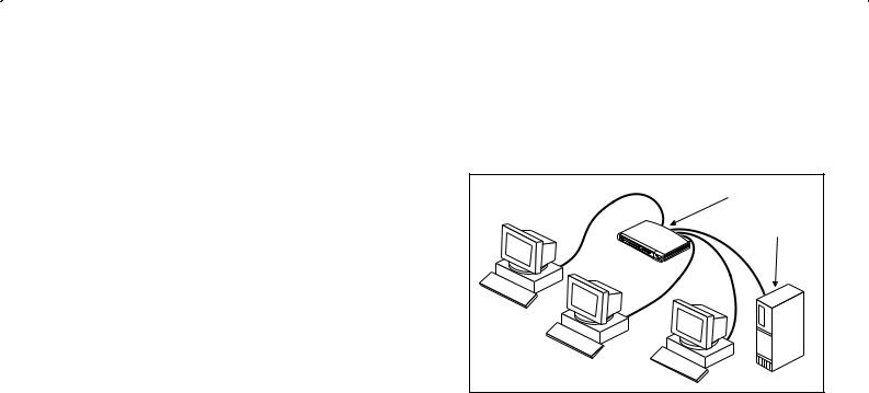
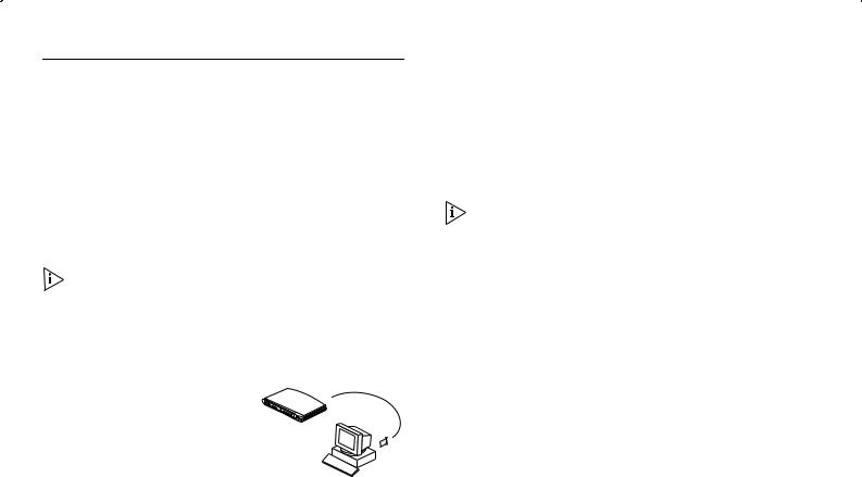
The OfficeConnect hub is a Fast Ethernet (Class II) repeater, allowing the creation of a network that runs 10 times faster than standard Ethernet. You can connect a workstation, server or other piece of equipment to each 100BASE-TX port, as shown in Figure 1. The Hub 4 has four 100BASE-TX ports, the Hub 8 has eight, and the Hub 12 has twelve.
Figure 1 Small Network Featuring OfficeConnect Fast Ethernet Hub 4 and Server
OfficeConnect hub |
Network server |
If you need to connect more workstations, simply use the stacking clip to connect another OfficeConnect hub to form a stack (each hub is a single Class II repeater).
5
CREATING YOUR NETWORK
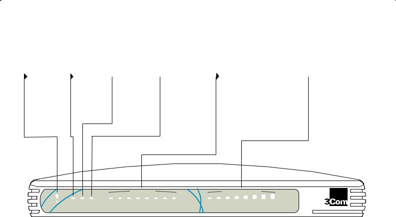
Fast Ethernet Hub 4 and Hub 8—Front
Alert LED |
Power LED |
orange |
green |
Alerts you to |
Indicates that |
excessive network |
the power |
use or a |
supply to the |
partitioned |
hub is present. |
100BASE-TX port. |
|
 Activity LED (Hub 4 only) yellow
Flashes each time a packet is received on a port.
 Collision LED yellow
Flashes each time a collision is detected at the hub. Collisions are part of normal network operation.
Port Status LEDs green/yellow
Indicates the status of each port. If nothing is connected, the LED is off. If green, the link between the port and the next piece of network equipment is OK.
If yellow, the port has partitioned due to a fault on that segment.
 Network Utilization LEDs (Hub 8 only) green/yellow/orange
Indicates how much your network is being used.
|
|
|
|
|
Port Status |
|
|
|
Network Utilization |
|
Alert |
Power Activity Collision |
1 |
2 |
3 |
4 |
5 |
6 |
7 |
8 |
1% 2% 3% 6% 12% 25% 50% 80% |
|
|
|
Green = OK, Yellow = Partitioned |
|
OfficeConnect Fast Ethernet Hub 8 |
|||||
|
|
|
|
|
|
|
|
|
|
|
6
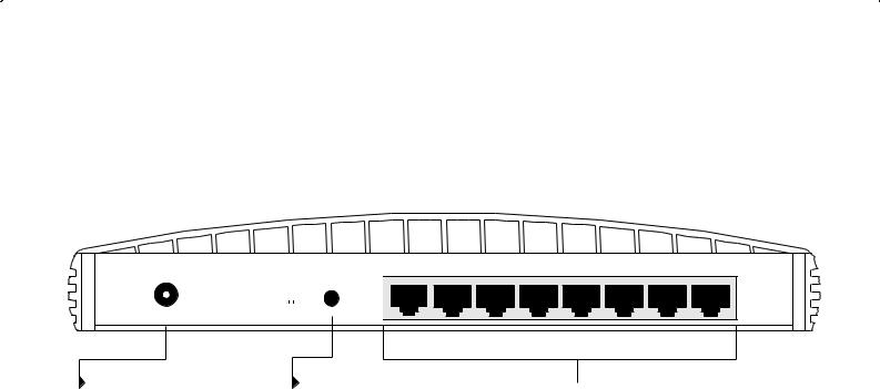
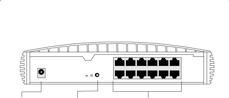
Fast Ethernet Hub 4 and Hub 8—Rear
POWER
|
|
|
|
|
|
|
|
|
|
|
|
|
|
|
|
|
|
|
|
|
|
|
|
|
|
|
|
|
|
|
|
|
|
|
|
|
|
|
|
|
|
|
|
|
|
|
|
|
|
|
|
|
|
|
|
|
|
|
|
|
|
|
|
|
|
|
|
|
|
|
|
|
|
|
|
|
|
Uplink/Normal |
8 |
|
|
|
|
|
|
|
|
|
|
||||||||||
|
|
|
|
|
|
|
|
|
|
|
|
|
|
|||||||||||
Power adapter socket |
|
|
|
|
Uplink/Normal switch |
|||||||||||||||||||
Only use the power adapter that is supplied with this OfficeConnect hub. Do not use any other adapter.
Affects the operation of the highest numbered port (port 4 on Hub 4 and port 8 on Hub 8). For connecting the port to a workstation, set to Normal (out). For connecting the port to another OfficeConnect unit, set to Uplink (in). Refer to the “Connecting OfficeConnect Hubs Together” section.
1X
 100BASE-TX RJ-45 ports
Use 100BASE-TX cable with RJ-45 connectors. You can connect the OfficeConnect hub to any workstation or piece of equipment that has a 100BASE-TX port. The highest numbered port can be used to link to another OfficeConnect unit. Refer to the “Connecting OfficeConnect Hubs Together” section.
7
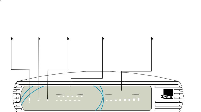
Fast Ethernet Hub 12—Front
Alert LED |
Power LED |
Collision LED |
orange |
green |
yellow |
Alerts you to |
Indicates that |
Flashes each time a |
excessive network |
the power |
collision is detected |
use or a |
supply to the |
at the hub. Collisions |
partitioned |
hub is present. |
are part of normal |
100BASE-TX port. |
|
network operation. |
Port Status LEDs |
Network Utilization LEDs |
green/yellow |
green/yellow/orange |
Indicates the status of each port. If |
Indicates how much your |
nothing is connected, the LED is off. |
network is being used. |
If green, the link between the port |
|
and the next piece of network |
|
equipment is OK. |
|
If yellow, the port has partitioned due |
|
to a fault on that segment. |
|
|
|
|
|
Port Status |
|
Network Utilization |
|
|
|
1 |
2 |
3 |
4 |
5 |
6 |
Alert |
Power Collision |
7 |
8 |
9 |
10 11 |
12 |
1% 2% 3% 6% 12% 25% 50% 80% |
Green = OK, Yellow = Partitioned
OfficeConnect Fast Ethernet Hub 12
8
Fast Ethernet Hub 12—Rear
POWER
 Power adapter socket
Only use the power adapter that is supplied with this OfficeConnect hub. Do not use any other adapter.
|
6X |
Uplink/Normal |
12 |
 Uplink/Normal switch
Affects the operation of the highest numbered port (port 12). For connecting the port to a workstation, set to Normal (out).
For connecting the port to another OfficeConnect unit, set to Uplink (in). Refer to the “Connecting OfficeConnect Hubs Together” section.
1X
7X
 100BASE-TX RJ-45 ports
Use 100BASE-TX cable with RJ-45 connectors. You can connect the OfficeConnect hub to any workstation or piece of equipment that has a 100BASE-TX port. The highest numbered port can be used to link to another OfficeConnect unit. Refer to the “Connecting OfficeConnect Hubs Together” section.
9
Before You Start
Your OfficeConnect hub comes with:
■One power adapter for use with the OfficeConnect hub
■A Product Registration card for you to fill out and return
■Four rubber feet
■A stacking clip
■Two unit labels and eight cable ties.
■An OfficeConnect Network Assistant CD-ROM.
The extra parts mentioned in the next section are not supplied with the hub.
Workstation Connections
To connect workstations or other equipment to your hub, you need:
1 A 100BASE-TX adapter card for |
|
each workstation. 3Com |
3 |
produce a range of easy to |
|
install network adapter cards, |
2 |
1
which provide your workstations with 100BASE-T connections.
2An operating system (for example, Netware or Windows 95/98) with network support configured, running on your workstations.
3One ‘Straight-through’ 100BASE-TX cable for each workstation or piece of equipment. A ‘Straight-through’ cable is one where the pins of one connector are connected to the same pins of the other connector; refer to Figure 5 on page 16. 100BASE-TX cable must be data grade (Category 5) shielded or unshielded. We recommend that you use shielded cable. The maximum length you can use is 100m (328ft).
In order to comply with the 100BASE-TX standard, ports designed for workstation connections have been marked with the graphical symbol ‘x’ (1x, 2x, 3x, ...). This denotes a crossover in the port’s internal wiring.
Hub Connections
To connect to another OfficeConnect hub, you need:
■One ‘Straight-through’ 100BASE-TX cable. The maximum length is 100m (328ft). Refer to “Connecting OfficeConnect Hubs Together” on page 13.
10
Stacking the Units Together
The Rubber Feet
The four self-adhesive rubber feet prevent your hub from moving around on your desk. Only stick the feet to the marked areas at each corner of the underside of your hub if you intend to place the unit directly on top of the desk. Do not fix the feet if you are going to use the clip.
The Stacking Clip
The blue stacking clip allows you to stack your OfficeConnect units together neatly and securely.
CAUTION: You can stack up to a maximum of four units. Smaller units must be stacked above larger units.
To fit the clip:
1Place your unit on a flat surface.
2Fit the clip across the top of the unit, as shown in Figure 2 (picture 1), ensuring that the longer sections of the fastening pieces are pointing downwards.
3Align the fastening pieces over the slots found on each side of the unit.
4Push the clip down gently to secure it, ensuring the fastening pieces snap into the slots on the unit.
To fit another unit:
1Rest the second unit on top of the clip and align it with the front of the unit below.
2Press down gently on the unit to secure it onto the clip, ensuring the fastening pieces fit into the slots on the unit below, as shown in Figure 2 (picture 2).
Figure 2 Stacking Your Units Together
1 |
Fastening |
2 |
|
|
|
|
Piece |
|
|
|
Fastening |
|
|
Piece |
To remove the clip:
1Remove the top unit together with the clip. If you hook a finger around one of the the fastening pieces and then pull it gently from out of the slot, the clip should come away with the upper unit attached to it.
2Push the clip in the center, so it bends towards the base of the unit, and then separate once the clip is loose.
11
 Loading...