

Page 1
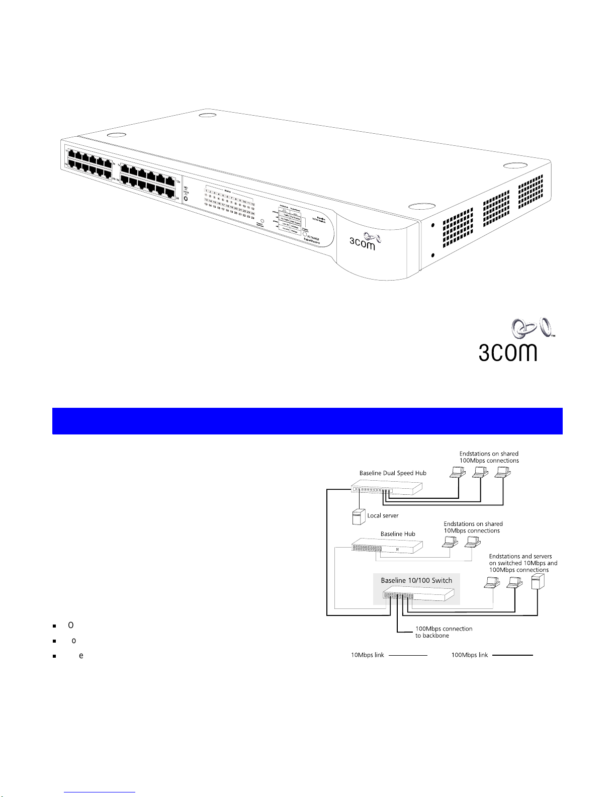
The SuperStack® 3 Baseline 10/100 Switch is a versatile,
easy-to-use unmanaged switch. It is ideal for users who want the
high-speed performance of 10/100 switching but do not need
sophisticated management capabilities. The Baseline 10/100
Switch is shipped ready for use. No configuration is necessary.
The Baseline 10/100 Switch has 12 or 24 shielded RJ-45,
10/100Mbps auto-negotiating ports on the front panel. Each port
automatically determines the speed and duplex mode of the
connected equipment and provides a suitable switched
connection.
The Baseline 10/100 Switch is suited for office use where it can
be free standing, or rack mounted (in a wiring closet or
equipment room).
The Baseline 10/100 Switch comes with:
One power cord for use with the Baseline 10/100 Switch
Four self-adhesive rubber pads
One mounting kit
The Switch can be powered either from the AC mains supply, or
through an optional 3Com SuperStack 3 Advanced Redundant
Power System (3C16071B). Contact your supplier for details.
The Baseline 10/100 Switch provides high performance switched
connections to 10Mbps and 100Mbps hubs, servers and
workstations that require a dedicated switched link.
I
NTRODUCTION
SuperStack® 3 Baseline 10/100 Switch 12-Port (3C16464B) an d
24-Port (3C16465B) User Guide
DUA1646-4AAA04
1
Page 2
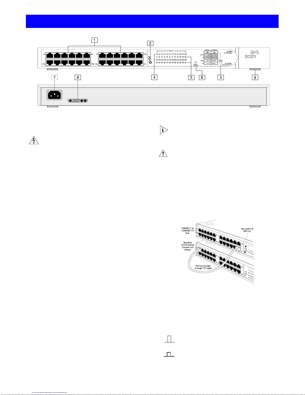
Numbered elements in this diagram refer to numbered sections in
the text. A 24-port unit is shown.
Front Panel
1
24 RJ-45 10/100 Ports and 1 RJ-45 1000 Port
WARNING
: RJ-45 ports.
These are shielded RJ-45 data
sockets. They cannot be used as telephone sockets. Only
connect RJ-45 data connectors to these sockets. Either
shielded or unshielded data cables with shielded or
unshielded jacks can be connected to these data sockets.
AVERTISSEMENT: Les ports RJ-45.
Il s’agit de prises
femelles blindées de données RJ-45. Vous ne pouvez pas
les utiliser comme prise de téléphone. Branchez uniquement des connecteurs de données RJ-45 sur ces prises
femelles. Les câbles de données blindés ou non blindés,
avec les jacks blindés ou non blindés, l’un ou l’autre, peuvent être branchés à ces prises de courant de données.
WARNUNG: RJ-45-Anschlüsse.
Dies sind abgeschirmte
RJ-45-Datenbuchsen. Sie können nicht als Telefonanschlußbuchsen verwendet werden. An diesen Buchsen
dürfen nur RJ-45-Datenstecker angeschlossen werden.
Diese Datenstecker können entweder mit abgeschirmten
oder unabgeschirmten Datenkabeln mit abgeschirmten
oder unabgeschirmten Klinkensteckern verbunden werden.
10BASE-T/100BASE-TX Ports
The Baseline 10/100 Switch has 12 (3C16464B) or 24 (3C16465B)
10/100Mbps auto-negotiating ports.
Ports 1-11 (3C16464B) or 1–23 (3C16465B) are MDIX ports. Each
can be connected to a device with an MDI port (such as a
workstation) using a normal ‘straight through’ TP (twisted pair)
cable. Alternatively, you can connect to a device with MDIX ports
using ‘cross-over’ TP cable.
Port 12 (3C16464B) or 24 (3C16465B) is ‘switch selectable’
MDI/MDIX usin g the MD I swit ch, as d escri bed in 2. Using this
port, you can connect to any other device without the need for
‘cross-over’ cable.
To connect a device to the Baseline 10/100 Switch, use Category
5 unshielded or shielded (screened) 100 Ohm TP cable (or
Category 3 cable for a 10Mbps connection). The maximum length
of cable for each connection is 100m (328ft). Connect one end of
the cable to an RJ-45 port on the Baseline 10/100 Switch, and
the other end to the appropriate RJ-45 port on the connecting
device.
Each port on the Baseline 10/100 Switch is auto-negotiating: its
speed and duplex mode (half duplex or full duplex) are
automatically determined by the capabilities of the connected
device. Each port can be connected to either a 10BASE-T or a
100BASE-TX device.
I
f you connect two Baseline 10/100 Switch units together,
the link between them operates at 100Mbps full duplex.
You must use Category 5 cable when connecting the
units.
CAUTION:
The Baseline 10/100 Switch supports full
duplex auto-negotiation. If the connected device does not
support auto-negotiation, the Switch will operate in half
duplex mode (even if the device is operating in full duplex
mode). In such a configuration, you may notice some
degradation of network performance. 3Com recommends
that you use devices that are capable of auto-negotiation
(and that you ensure that auto-negotiation is enabled, if
it is a configurable option).
To connect the Baseline 10/100 Switch to a SuperStack 3 hub
using a normal ‘straight through’ cable, connect any port on the
Baseline 10/100 Switch to the MDI/MDIX port on the hub, as
shown below. Ensure that the MDI switch on the hub is in (MDI).
An alternative method of connecting the Baseline 10/100 Switch
to a hub using a normal ‘straight through’ cable is to connect any
MDIX port on the hub to the MDI/MDIX port on the Baseline
10/100 Switch, ensuring that its MDI Switch is set to in (MDI).
You can us e ‘cross-over’ TP cable to connect any MDIX port on
the Baseline 10/100 Switch to any MDIX port on a hub.
2
MDI Sw itch
This switch affects port 12 (3C16364B) or port 24 (3C16465B):
H
OW TO
U
SE THE
B
ASELINE
10/100 S
WITCH
Out
Port 12 or 24 is a n MDIX p ort .
It can be connected to a device with an MDI port (such
as a workstation) using a normal ‘straight throu gh’ TP
cable.
In
Port 12 or 24 is a n MDI p ort.
It can be conn ect ed to an MDIX port on a device (su ch
as a hub) usin g a n orm al ‘straight through’ TP cable.
!
MDIX
MDI
2
Page 3

3
Display Function Switch
This switch affects the Status LEDs described in 4 and 5.
4
Activity/Duplex Status LEDs
The first (top) and third row of LEDs, which are colored yellow,
show the activity or duplex status of the related ports:
When the Display Function switch is out (its normal position),
these LEDs show the activity of each port. The LED flashes
when packets are received or transmitted on the port.
When the Display Function switch is pressed in, these LEDs
show the duplex status of each port:
5
Link/Speed Status LEDs
The second and fourth (bottom) row of Status LEDs, which are
colored green, show the link or speed status of the related ports:
When the Display Function switch is out (its normal position),
these LEDs show the link status of each port:
When the Display Function switch is pressed in, these LEDs
show the speed status of each port:
6
Power/Self Test LED
The Power/Self test LED shows a number of conditions:
Rear Panel Connections
7
Power S upply
The Baseline 10/100 Switch automatically adjusts to the supply
voltage. Only use the power cord that is supplied with the
Baseline 10/100 Switch.
8
Socket for Re dundant Po wer System (RPS)
Only connect a 3Com SuperStack 3 Advanced RPS (3C16070,
3C16071, 3C16071A or 3C16071B) to this socket. An
appropriate power module and cable is required. The connector
on the Baseline 10/100 Switch is a Type 2 socket. For details,
follow the installation instructions in the guides that accompany
the Advanced RPS and the power module.
CAUTION: When connecting an RPS power module cable
to the unit, take off the protective cover by removing the
fixings with a suitable tool. Keep the cover and the fixings in a safe place. If you remove the RPS power module
cable at any time, you must replace the protective cover.
9
Self-adhesive Pads
The unit is supplied with four self-adhesive rubber pads.
You do not need to apply the pads if you intend to rack
mount the unit.
If th e un it i s to be p art of a free sta ndi ng st ack , ap ply the pad s to
each marked corner area on the underside of the unit. Place the unit
on top of the lower unit, ensuring that the pads locate with the
rece sse s o f th e lo we r u nit .
Positioning the Baseline 10/100 Switch
CAUTION: If installing the Baseline 10/100 Switch in a
stack of different size SuperStack 3 units, the smaller
units must be installed above the larger ones. Do not
have a free standing stack of more than six units.
When deciding where to position the Baseline 10/100 Switch
ensure:
It is accessible and cables can be connected easily.
Cabling is away from sources of electrical noise such as
radios, transmitters and broadband amplifiers, and away from
power lines and fluorescent lighting fixtures.
Water or moisture cannot enter the case of the unit.
Air flow around the unit and through the vents in the side of
the case is not restricted (3Com recommend that you provide
a minimum of 25mm (1in.) clearance).
To prolong the operational life of your units:
Never stack units more than six high if free standing, and
ensure that cables are supported so that they do not cause
the stack to fall over.
Do not place objects on top of any unit or stack.
Do not obstruct any vents at the sides of the case.
Rack Mounting
The Baseline 10/100 Switch can be mounted in a 19-inch equipment rack using the Mounting Kit. Refer to “Mounting Kit
Instructions” on page 5.
Power Up
Use the following sequence to power up the Baseline 10/100
Switch :
Check the network connections and cables.
Connect the power supply cable to the appropriate power
socket on the rear panel of the unit; refer to 7 or 8.
Connect the plug to the power supply outlet socket and
switch on the power supply at the socket. If you are using
the Advanced Redundant Power System, ensure it is powered on.
When the switch is powered on, the Power/Self Test LED should
first flash green, then stay lit. If it does not, refer to 6.
Spot Checks
At frequent intervals you should visually check the Baseline
10/100 Switch. Regular checks can give you an early warning of a
possible failure; any problems can then be attended to when
there will be least effect on users. Check the following:
If you experience any problems operating the Baseline 10/100 Switch,
refe r to “Problem Solving” on page 5.
Out
This is t he no rma l po sition of th e swi tch.
The St at us L ED s s ho w t he Ac ti vi ty a nd L ink St at us of
each p ort .
In
When the switch is pressed in, the Status LEDs show
the Dup l ex a nd S pe ed St atu s of eac h p ort . Th e s wi tch
returns to the out pos ition whe n released.
On
The port is operating in full duplex mode.
Off
Ports 1 to 24: If the link is established, the port is operating in
half du plex mode.
On
The li nk h as be en es ta bli she d a nd th e seg men t a tt ac h ed t o th e
port is functional.
Off
The link has not bee n es tabli sh ed. Ei ther no thin g is conn ecte d
to the port, or there is a problem:
■
Check that the atta ched dev ice is power ed on.
■
Check that the cab le is the c orrec t type and i s not faul ty.
If the LED i s off f or por t 12 ( 3C1 646 4B) o r 2 4 (3C 16465 B) ,
check the setting of the MDI switch. Refe r to 2. Try toggling the
MDI switch.
If the port is conn ected to anoth er unit’s MDI/MDIX port, check
the othe r u nit’s MDI switch position .
If these ch eck s do no t i den tify the cau se of a proble m, i t m ay
be that the unit or the device connected to the port is faulty.
Contac t yo ur s uppl ier fo r f urt her a dvi ce.
On
The link is operating at 100Mbps.
Off
If the link is pre sent, it is op er ating at 10Mb ps.
Green
The unit is powered on and ready for use.
Flashing
green
The unit is performing its power up procedure. If the LED is still
flashing gre en 1 min ute a fter po wer u p, th ere i s a f au lt. C ontact your s upp lier.
Yellow
The unit has fa ile d. Po we r off t he unit , wa it f ive se con ds a nd
power on th e u nit. C o ntac t yo ur s uppl ier i f the LE D c onti nues
to light yellow.
Off
The unit is not receiving power:
■
Check the power cord is connected correctly.
■
If the unit still does not operate, contact your supplier.
Cabling Check that all external cabling connections are secure
and th at no c ab les are pu l led ta ut.
Cooling fa ns Where p os si bl e, che ck th at th e c o oli ng fa ns are op er at -
ing by liste ning to the unit . The fan s a re fi tted near to
the front right hand side of the unit (when viewed from
the front) .
!
3
Page 4

Please read the following safety information carefully before
installing the Basel ine 1 0/100 Swit ch.
WARNING:
Installation and removal of the unit must be carried out
by qualified p ersonn el only.
If installing the Switch unit in a stack with SuperStack 3 Hub units, the
Baseline 10/100 Switch unit must be installed below the narrower Hub
units.
The unit must be connected to an earthed (grounded) outlet to comply
with int ernat ional sa fety sta ndards.
Do not connect the unit to an A.C. outlet (power supply) without an
earth (g round) co nnection .
The appli ance cou pler (the connecto r to the unit and not the wall p lug)
must have a configur ation for matin g with an EN 60320/IE C320
appliance inlet.
The socket outlet must be nea r to the uni t and ea sily acce ssible . You
can only remove pow er from the un it by disc onnec ting the po wer cord
from the ou tlet.
This u nit op erat es under SELV (Safet y Ex tra Lo w Voltag e) c ondi tion s
according to IEC 60. The conditions are only maintained if the
equipme nt to wh ic h it is conn ect ed a lso opera te s und er SELV condi tion s.
Only c onnec t an Advance d Redunda nt Powe r System ( 3C16070,
3C16071 , 3C16071A or 3C16 071B) or Redundant Power System
(3C565047) to the Redundant Power System socket.
France and Peru onl y
This unit cannot be powered from IT
†
supplies. If you r supplies are of IT type, thi s
unit must be powered b y 230V ( 2P+T) via an is olat ion tra nsfor mer ra tio 1: 1, w ith t he
secondary connec tion poin t labelled Neut ral, conne cted directly t o earth (ground).
†
Impédance à la terre
Power Cord Set
This must be appro ved for the country wh ere it will be us ed. e.g.
Veuillez lire à fond l 'in formatio n d e la s écurité suiv ante avan t
d'installer le Base line 10/100 Sw itch .
AVERTISSEMENT:
L’installation et la dépose de ce gro upe doivent
être confiés à un personn el qualif ié.
Si vous entassez l’unité Switch avec les unités SuperSta ck 3 Hu b, l’unité
Baseline 10/100 Switch doit être install ée en de ssous des unités Hub
plus étroites.
Ne branch ez pas v otre appa reil sur une prise se cteur (a limentat ion
électriqu e) lorsqu' il n'y a pa s de conn exion de mise à la te rre (mise à la
masse).
Vous devez racco rder ce gro upe à une sortie mise à la terre (mise à la
masse) afin de respecter le s normes inter nationales de sécurité.
Le coupleur d’appareil (le con necteu r du groupe e t non pas l a prise
murale) doit resp ecter une config uration qu i perm et un bra nchemen t
sur une entrée d’appareil EN 60320/IE C 320.
La pris e secteur d oit se trouver à prox imité de l ’appareil et son accès
doit être facile. Vous ne p ouvez m ettre l’appa reil hors circuit qu ’en
débrancha nt s on cord on él ectri que a u niv eau de cett e pr ise.
L’appareil fonctionne à une tension extrêmement basse de sécurité qui
est conforme à la norme IEC60950. Ces con ditions ne sont main tenues
que si l’équipement auquel il est raccordé fonctionne dans le s mêmes
conditions.
Branchez uniquement un Advanced Redu ndant Po wer Syst em
(3C16070, 3C16071, 3C 16071A ou 3C16071B) ou un Redundant Power
System ( 3C56504 7) sur la prise femelle du Redundant Power System.
France et Pérou uniquement:
Ce groupe ne peut pas être al im enté par un dispositif à imp édance à la terr e. S i vos
alimentations so nt du type impédance à la terre, ce groupe doit être alimenté par
une tension de 230 V (2 P+T ) par le bia is d’un transformateur d’isolement à rapport
1:1, avec un poin t secondai re de connexion p ortant l’appe llation Ne utre et avec
raccordement direct à l a t erre (ma ss e).
Cordon électrique
Il doit être agréé da ns le pays d ’utilisation.
Bitte unb edingt vor dem Einbau en des Bas elin e 10/100 Sw itch
Einheit die fo lgenden Sic herheitsa nweisunge n durchlesen .
WARNUNG:
Die Installa tion un d der Aus bau des Geräts da rf nur
durch Fach perso nal erfolge n.
Wenn die Baseline 10/100 Switch Einheit in einer Stapel mit anderen
SuperStac k 3 Hub Ei nheiten e ingebaut werden soll , muß die Ba seline
10/100 Sw itch Ein heit unte r die sc hmaleren H ub Einhei ten einge baut
werden.
Das Gerät nicht an ein e Wechse lstromstec kdose a nsch ließen, die nicht
geerdet is t.
Das Gerät muß an eine geerd ete Stec kdose an geschloss en werde n, die
die int ern ati onal en Sic herh eit snor men er füllt.
Der Gerätestecker (der Anschluß an das Ge rät, nicht d er
Wandsteckdosenstecker) muß eine passende Konfi guration f ür einen
Geräteeingang ge mäß EN60320/ IEC320 ha ben.
Die Netzsteckdose muß in der Nähe des Geräts und leicht zugänglich
sein. Die St romver sorgung de s Geräts kann nu r durch Hera uszie hen des
Gerätene tzkabel s aus der Netzst eckdos e unterbro chen we rden.
Der Betrieb dieses Geräts erfolgt un ter den SELV-Bedingungen
(Sicherheitskleinst spannung) ge mäß IEC 60. Diese B edingungen sind nur
gegeben, wenn auch di e an das Gerät angeschl ossenen Ge räte unter
SELV-Bedingungen betri eben werden.
Nur ein
Advanced Redundant Power Syste m (3C16070, 3C 16071,3C16 071A
oder
3C16071B)
oder
Redundant Power Syst em (3C565 047)
an den
Redundant Power System
Anschluß anschließen.
S
AFETY INFORMATION
U.S.A . an d
Canada
■
The cord set must b e UL-appr oved an d CSA ce rtified .
■
The minimum specifications for the flexible cord are:
No. 18 AWG
Type SV or SJ
3-conductor
■
The cord set must have a rated current capacity of at least
10A.
■
The atta chment plu g must be an earth -groundi ng type
with a NEMA 5 -15P (15 A, 125V) or N EMA 6-15 P (15A,
250V) conf igurati on.
Denmark
■
The suppl y plug mus t comply w ith Sect ion 107- 2-D1,
Standard DK2-1a or DK2-5a.
Switzerland
■
The suppl y plug mus t comply w ith SEV/A SE 1011.
UK
■
The suppl y plug mus t co mply with B S1 363 ( 3-pi n 13 -a mp)
and be fitted with a 5A fuse which complies with BS1362.
■
The mains cord must be <HAR> or <BASEC> marked and
be of type HO 3VVF3 GO.75 (m inimum).
Europe
■
The suppl y plug mus t comply w ith CEE7/7 (“SCHUKO”)
■
The mains cord must be <HAR> or <BASEC> marked and
be of type HO 3VVF3 GO.75 (m inimum).
L’
INFORMATION DE
S
ÉCURITÉ IMPORTANTE
Etats-U nis et
Canada:
■
Le cordon doit a voir reçu l’hom ologatio n des UL et un
certificat de la CSA.
■
Le cordon soupl e doit respect er, à titre minimum, les
spécifications suivantes:
calibre 18 AWG
type SV ou SJ
à 3 conducteurs
■
Le cordon doit être en mes ure d’a chemin er un courant
nominal d’au mo ins 1 0 A.
■
La prise femelle de brancheme nt doit êt re du type à mise à la
terre (mise à la masse) et resp ect er l a con fig urat ion NEM A
5-15P (15 A, 125 V ) ou NEMA 6- 15P (15 A, 250 V).
Danemark:
■
La prise mâle d’alimentati on doit respec ter la section 107-2 D1
de la norme DK2 1a ou DK2 5a.
Suisse:
■
La prise mâle d’alimentation doit respecter la norme SEV/ASE
1011.
Europe
■
La prise secteur doit être conforme aux normes CEE 7/7
(“SCHUKO”)
■
LE cordon secteur doi t porter la mention < HAR> ou <BASE C>
et doit être de type HO3VVF3GO.75 (minimum).
W
ICHTIGE
S
ICHERHEITSINFORMATIONEN
Stromkabel
. Dies muss von de m Land, in dem es benut zt wird geprüft werden:
Schweiz
■
Dieser Str oms tecke r muß die SEV/ASE 1011Be stimmun gen
einhalten.
Europe
■
Das Netzkabel muß vom Typ HO3VVF3GO.75
(Mindestanforde rung) sein und die Aufs chrift <HAR> oder
<BASEC> tragen.
■
Der Netzstecker muß die Norm CEE 7/7 er füllen (”SCHUKO”).
4
Page 5

Introduction
The Baseline 10/100 Switch is supplied with two mounting
brackets and four screws. These are used for rack mounting the
unit. When mounting the unit, you should take note of the
guidelines given in “Positioning the Baseline 10/100 Switch” on
page 3.
Rack Mount ing the U nits
The Baseline 10/100 Switch is 1U high and will fit a standard
19-inch rack.
CAUTION: Disconnect all cables from the unit before
continuing. Remove the self-adhesive pads from the
underside of unit, if already fitted.
1
Place the unit the right way up on a hard, flat surface with
the front facing towards you.
2
Locate a mounting bracket over the mounting holes on one
side of the unit.
3
Insert the two screws supplied in the mounting kit and fully
tighten with a suitable screwdriver.
4
Repeat the two previous steps for the other side of the unit.
5
Insert the u nit int o the 19 -inc h rack a nd se cure with suita ble
screws (not provided).
6
Reconnect all cables.
Refer to the information about LEDs given earlier in this guide to
see if the problem can be identified and rectified. Here are some
common problems that can occur:
Link Status LED not lit for a port that has a connection.
There is a problem with this connection. Check that:
The device being connected to is powered on and operating
correctly.
The cable is connected at both ends.
That you are using a TP cable that is:
■
‘Straight through’, to connect an MDIX port to an
MDI port.
■
‘Cross-over’, to connect an MDIX port to an MDIX
port, or an MDI port to an MDI port.
The cable is not damaged.
If the connection is to a workstation, that the workstation’s
network interface is installed and configured correctly.
All Ac tivit y LEDs appea r to be lit co ntinua lly.
There m ay b e
broadcast storms on the network. Remove port connections one
at a time, waiting a few seconds between each port. If the LEDs
go off after removing a port connection, the device that was
connected to that port is introducing an excessive amount of
broadcast frames to the network (some pieces of network
equipment operate by sending out broadcast frames regularly).
Refer t o the docum enta tion t hat a ccomp anies the dev ice fo r
information on disabling the broadcast operation.
If the problem persists and the unit still does not operate
successfully, contact your supplier with the following information
before returning the unit:
Product number and serial number (printed on a label supplied with the unit)
A brief description of the fault
Related Standards
The SuperStack 3 Baseline 10/100 Switch has been designed to
the following standards:
Environmental
Physical
Electrical
M
OUNTING
KIT I
NSTRUCTIONS
P
ROBLEM
S
OLVING
T
ECHNICAL INFORMATION
Functional
ISO 8802 -3, IE EE 8 02.3 (Eth er net ), IE EE 8 02.3u ( Fast
Etherne t), I EEE 802. 3x ( Flow C ontro l)
Safety
UL 1950, E N 60 950 , CSA 22.2 #9 50, IE C 60 950
EMC Emissions
EN 55022 Class B, FCC Part 15 Subpart B Class A,
ICES -00 3 Cla ss A, VCCI Class B*, AS /NZS 354 8 Cla ss B,
CNS 13438 Class A
*Category 5 scree ned ( shie lded) cable s mus t be used to
ensure com pl ian ce w ith the C l ass B re qu irem en ts of thi s
standard. The use of unscreened cables (Category 3 or
5 for 10 BASE-T p orts o r C ate gory 5 for 10 0BAS E-TX
ports) complies with the Class A requirements.
Immunity
EN 55024
Operating Temperature
0–50°C (32–122°F)
Humidity
10–95% (non-con de nsing )
Standard
EN 6006 8 (IEC 68) —va riou s pa rts
Width
440mm (17. 3in.)
Depth
235mm (9.3 in. )
Height
44mm (1.7in.) or 1U
Weight
2.6kg (5.8lb)
Mounting
Free standi ng, or 19in . ra ck mo un ted us ing the m ou nting kit su pp lied
Power Inlet
IEC 320
AC Line Frequency
50/60 Hz
Input Voltage
90–240 VAC
Current Rating
1 Amps (m aximum )
Maximum Power
Consumption
3C16464B: 49 VA
3C16465B: 88 VA
Maximum Power
Dissipation
3C16464B: 165 B TU/ hr
3C16465B: 300 B TU/ hr
5
Page 6

This wa rra nty appli es to cu stom ers loca ted in th e Uni ted Stat es, Aus trali a, Canad a
(except Quebec), Ireland, New Zealand, U.K., and othe r English l anguage cou ntries,
and countries for w hich a tr anslation int o the local l anguage is no t provided
SuperStack 3 Base line 10/100 Swit ch 12-Po rt (3C16464B ) and
24-Port (3C16465B)
HARDWARE:
3Com warrants to the end u ser ("Custom er") that this ha rdware
product will be free from de fects in w orkmanship a nd materi als, under no rmal use
and service, for the follow ing length of time from the da te of pu rchase from 3Com
or its a uthor ize d rese ller :
Lifetime, for as l ong as the or iginal Custom er owns the product (not transferabl e to
a subsequent end us er)
3Com's sole oblig ation under t his express war ranty shall be , at 3Com' s option a nd
expense, to repair the defective p roduct or par t, deliver to C ustomer a n equivalent
product or part to repla ce the defect ive item, or if neither of the two f oregoing
options is reasonably a vailable, 3 Com may, in its sole disc retion, refund to C ustomer
the purchase price pai d for the d efective produc t. All product s that are replace d will
become the property of 3Com. Repl acement products or part s may be ne w or
reconditioned. 3Com w arrants an y replaced or repa ired product or pa rt for ninety
(90) days from shipm ent, or the remai nder of the i nitial warra nty period, w hichever
is long er.
SOFTWARE:
3Com warrants to Customer that each software program licensed from
it, except as note d below, will perform i n substa ntial conforma nce to its program
specifications, for a period of ninety (90) days from the date of purchase from 3Com
or its authorized rese ller. 3Com warrants the me dia containi ng software agai nst
failure during the war ranty period. N o updates are provided, u nless specifica lly
included in the Included Serv ices section. 3Com's sole obligation under this e xpress
warranty shall be, a t 3Com's opt ion and ex pense, to refund the purchase price paid
by Customer for a ny defective software prod uct, or to replace any defec tive media
with software which substantia lly conforms t o applica ble 3Com pu blished
specifications. Customer assumes responsibility for the selection of the appropriate
applications program and associa ted reference ma terials. 3C om makes n o warranty
or representation that it s software product s will meet Customer's requirements or
work in combinati on with any ha rdware or appl ications sof tware products provi ded
by third parties, that the oper ation of the soft ware products will be unin terrupted or
error free, or that all defects in the software products will be correcte d. For any third
party products liste d in the 3Com s oftware product documen tation or spe cifications
as being compatibl e, 3Com wi ll make reaso nable efforts t o provide compa tibility,
except where the non- compatibili ty is caused b y a "bug" o r defect i n the third
party's product or from use of the s oftware product not in accorda nce with 3Com 's
published specifica tions or use r manua l.
THIS 3C OM PROD UCT M AY INCLUDE OR BE B UND LED WI TH (1 ) THI RD PARTY
SOFTWARE, OR (2 ) 3C OM S OFTWARE THAT IS LICE NSED "A S IS" , TH E U SE OF
WHICH IS GOVERNED BY A SEPARATE END USER LICENSE AGREEMENT. THIS 3COM
WARRANTY DOES NOT APP LY TO SUCH THIRD PARTY SOFTWARE OR 3COM
SOFTWARE LICENSED "A S IS". FOR T HE APPLICA BLE WARRANTY, PLEASE REFER TO
THE END US ER LICEN SE AGR EEM ENT GOVE RNIN G THE U SE OF SUCH SO FTWARE OR
THE ACCO MPANYING DO CUME NTATION RELATING TO SUCH SOFTWARE.
YEAR 2000 WARRANTY:
In addition to the Hardware Warranty and Software
Warranty stated above, 3Com warrant s that ea ch product sold or licensed to
Customer on and aft er January 1, 1998 tha t is date se nsitive wi ll continue
performing properly with regard to such d ate data on and afte r January 1, 200 0,
provided that all ot her products us ed by Custo mer in conn ection or c ombination
with the 3Com produc t, including ha rdware, software, and fir mware, accurate ly
exchange date dat a with the 3C om product, w ith the exce ption of those products
identified at 3Com's Web s ite, http:/ /www.3com.com/products/yr 2000.html, as not
meetin g th is st and ard. If it a ppe ars that any produ ct th at is st ated to m eet t his
standard does not p erform properly w ith regard to suc h date data o n and afte r
January 1, 20 00, and C ustome r no tif ies 3Com wit hin nine ty (90) days after purch ase
of the product from 3Com or its aut horized resell er, 3Com shall, at its optio n and
expense, provide a sof tware updat e which would effect the pro per performanc e of
such product, repair suc h product, delive r to Custo mer an equiva lent product to
replace such product, or if none of the foregoi ng is feasibl e, refund to Customer the
purchase price paid for such produc t.
Any software upd ate or replac ed or repa ired produ ct will c arry a Year 2000 Warranty
for ninety (90) days after purchase.
OBTAINING WARRANTY SERVICE:
Customer mus t contact a 3 Com Corpor ate
Servic e Cent er or an Aut hor ized 3Co m Serv ice Ce nt er wi thin t he ap plic abl e warr ant y
period to obta in warrant y se rvice a uthor ization. Dated proof of purchase from 3Com
or its authorized rese ller may be required. Product s returned t o 3Com's Corpor ate
Service Center mus t be pre-author ized by 3C om with a Us er Service Order (USO)
number (or a Return Mat erial Authori zation (RMA) num ber or a Service Repair Order
(SRO) number, whichever was issued ) marked on t he outside of the package , and
sent prepaid and pack aged appropriat ely for safe shipment, a nd it is recom mended
that they be insu red or sent by a method th at provides for tracking of t he packa ge.
Responsibility fo r loss or da mage does not transfe r to 3Com unt il the retur ned item
is received by 3Com. Th e repaired or replace d item wil l be shipped to C ustomer, at
3Com's expense, not later than t hirty (30) days after 3C om receives th e defective
product, and 3Com w ill retain risk of loss or d amage until the item is delivered to
Customer.
3Com s hal l no t b e re spo nsi ble f or an y sof twa re, firm wa re, i nfo rma ti on, or mem or y
data of Customer co ntained in, stored on, or i ntegrated w ith any product s returned
to 3Com for repair, whether under warra nty or not .
Dead- or Defective-on-Arrival
. In th e e ven t a pro duc t co mpl et ely fai ls to fu n cti on
or exhibits a defect in materials or workmanship within the first forty-eight (48)
hours of instal lation b ut no late r than thi rty (3 0) da ys af ter the date of purch ase, and
this is verifie d by 3Co m, it will be considered dead- or defe ctive-on- arriva l (DOA) a nd
a replacement shall be provided pr ior to 3Com rece iving the defective product , but
only if Customer provides a purcha se order number, credit card number, or other
method of payme nt acceptabl e to 3Com, to be used if 3Com nee ds to charge
Customer for the replacement, a s explained be low. The replacemen t product will
normally be shippe d not later t han three (3) business d ays after 3Co m's verifica tion
of the DOA product, bu t may be de layed due to export or i mport procedures. T he
shipment of a repla cement product prior to 3C om receiving t he defec tive product is
subject to local l egal requirement s and may no t be availa ble in all locations. Whe n
such a replacement is provided an d Custome r fails to retu rn the or iginal product to
3Com within fift een (15) da ys after s hipment of the replacement, 3C om wi ll charge
Customer for the replacement pr oduct, at lis t price.
Shipment of a Rep lacement P rior to 3Com Rec eiving the Defective Product
is
provided for five (5) years, after which time it may be available for a specified fee,
but in either case only if C ustomer provi des a purchase order number, credit card
number, or other method of payme nt acceptab le to 3Com, t o be used i f 3Com
needs to charge Customer for the replacement, as explained below. 3Com will make
commercially reasonable efforts to ship the replacement product not later than five
(5) business days after receiv ing the request f or a replaceme nt, but may be delayed
due to product avai lability or export or i mport procedures. The shipment of a
replacement product prior to 3Com receiving the defec tive product is subject to local
legal requirements a nd may not be available in all locati ons. When su ch a
replacement is provid ed and Custom er fails to return th e original product to 3Com
within fifteen (15) days after shipment of the replacement, 3Com will charge
Customer for the replacement, at list price. This replacement prior to 3Com receiving
the defective product is different from th e fee- based A dvance Ha rdware Repla cemen t
Service, which is available as a contracted service offering.
INCLUDED SERVICES:
3Com's Electronic Support Services
, available at no charge, include 3Com
Knowledgebase, in formation on known bug s, documen tation, release notes, and
publicly availa ble software a nd firmware upgr ades. 3Com reserves the ri ght to
modify or cancel this offering a t any time, w ithout adva nce notice .
Telephone Technical Support
, with coverage for basic troubleshooting only, will be
provided at no addi tional char ge for 12 months from the date of purcha se, on a
commercially reas onable effor ts ba sis. Telephone support i s provided by 3Com onl y i f
Customer purchase d this product directly from 3Com , or if Cust omer's resell er is
unable to provide tel ephone supp ort. To qualify for this telepho ne technical s upport,
Customer must regi ster on the 3C om Web s ite at
http://support.3C om.com/inde x.htm, and s tate the da te of purchas e, product
number, and serial number. 3Com's response to a reques t for telephone technical
support will be in the form of a retur n call from a 3Com representat ive by close o f
business the following bus iness day, defined as 9 a.m. to 5 p.m., local time, Monday
through Friday, excluding local holida ys. Please ref er to the Technical Support
appendix in the User Guide for telephone numbers .
Software Up dates
, All software and firmware upgrades and the latest code for this
product download ed through the 3C om Software Li brary.
WARRANTIES EXCLUSIVE
: IF A 3C OM PROD UCT D OES NOT OPER ATE AS
WARRANTED ABOVE , CUST OMER 'S SOL E REME DY FO R BREA CH O F THAT
WARRANTY SHALL BE REPAIR, REPLACEMENT, OR REFUND OF THE PURCHASE PRICE
PAID, AT 3COM'S OPTION. TO THE FULL EXTENT ALLOWED BY LAW, THE
FOREGOIN G WARRAN TIES AND REME DIES ARE EXC LUSI VE AND A RE IN L IEU OF AL L
OTHER WARRANTIES, TERMS, OR CONDITIONS, EXPRESS OR IMPLIED, EITHER IN
FACT OR BY OPERATION OF LAW, STATUTORY OR OTHERWISE, INCLUDING
WARRANTIE S, TE RMS, OR CON DITI ONS OF MERC HANTABILIT Y, FITNESS FOR A
PARTICULAR PURPOSE, SATISFACTORY QUALITY, CORRESPONDENCE WITH
DESCRIPTION, AND NON-INFRINGEMENT, ALL OF WHICH ARE EXPRESSLY
DISCLAI MED. 3COM NEIT HER AS SUMES NO R AUTH ORIZ ES ANY OTHER PER SON T O
ASSUME FOR IT ANY OTHER LIABILITY IN CONNECTION WITH THE SALE,
INSTALLATION, MAINTENANCE OR USE OF ITS PRODUCTS.
3COM SH ALL N OT B E LIABL E UN DER T HIS WARRA NTY IF ITS TEST ING AN D
EXAMINATION DISCLOSE THAT THE ALLEGED DEFECT OR MALFUNCTION IN THE
PRODUCT DOES NOT EXIST OR WAS CAUSED BY CUSTOMER'S OR ANY THIRD
PERSON'S MISUSE, NE GL EC T, IMPROP ER IN STALLATIO N O R TE ST IN G , UN A UT HO RI ZE D
ATTEMPTS TO OPEN, REPAIR OR MODIFY THE PRODUCT, OR ANY OTHER CAUSE
BEYOND THE R ANGE O F THE INTE NDED USE, OR BY AC CIDE NT, FIRE, LIG HTNIN G,
POWER CUTS OR OUTAGES, OTHER HAZARDS, OR ACTS OF GOD.
LIMITATION OF LIABILITY
: TO TH E FU LL EX TENT ALLO WED BY L AW, 3COM ALS O
EXCLUD ES F OR I TSEL F AND IT S SU PPLI ERS A NY L IABI LIT Y, WHETHER B ASED IN
CONTRACT OR TORT (INCLUDING NEGLIGENCE), FOR INCIDENTAL,
CONSEQUENTIAL, INDIRECT, SPECIAL, OR PUNITIVE DAMAGES OF ANY KIND, OR
FOR LOSS OF REVENUE OR PROFITS, LOSS OF BUSINESS, LOSS OF INFORMATION OR
DATA, OR OTHER FINANCIAL LOSS ARISING OUT OF OR IN CONNECTION WITH THE
SALE, INSTALLATIO N, MA IN TENA NCE, USE , PER FORM ANC E, FAI LURE , OR
INTERRUPTION OF ITS PRODUCTS, EVEN IF 3COM OR ITS AUTHORIZED RESELLER
HAS BEEN ADVISED OF THE POSSIBILITY OF SUCH DAMAGES, AND LIMITS ITS
LIABILITY TO REPAIR, REPLACEMENT, OR REFUND OF THE PURCHASE PRICE PAID, AT
3COM'S OPTION. THIS DISCLAIMER OF LIABILITY FOR DAMAGES WILL NOT BE
AFFECTED IF ANY REMEDY PROVIDED HEREIN SHALL FAIL OF ITS ESSENTIAL
PURPOSE.
DISCLAIMER:
Some countries, state s, or provinces d o not all ow the exclusi on or
limitation of im plied warra nties or t he limitati on of incident al or cons equential
damages for cer tain product s supplied to consumers, or the limi tation of liability for
personal injur y, so the above limitations and exclusi ons may be l imited in the ir
application to you . When the implied warranties a re not allowed t o be exclude d in
their entirety, they will be limited to the duration of the applicable written warranty.
This warranty gi ves you sp ecific legal r ights which m ay vary d epending on local la w.
GOVERNING LAW:
This Limited Warranty shall be governed by the laws of the State
of Cal ifor ni a, U. S.A. , an d by the l aws of the U nit ed St ate s, ex clu ding th eir co nfl icts
of laws principles . The Unite d Nations Co nvention on Contracts for the Inter national
Sale of Goods is hereby exclude d in its ent irety from applica tion to this Limited
Warranty.
3Com Corporati on
5400 Bayfront Plaza
P.O. Box 58145
Santa Clara, CA 95052-8145
(408) 326-5000
August 2000
3Com reserves th e right to modi fy or canc el this offe ring at any ti me, without
advance notice. This offering is n ot avail able where prohibi ted or restricted by law.
L
IMITED
W
ARRANTY
6
Page 7

FCC Statement
This equipment ha s been teste d and found to compl y with the lim its for a Class A
digital device, pur suant to pa rt 15 of t he FCC rules . These limi ts are designed t o
provide reasonable protectio n against ha rmful int erference wh en the equip ment is
operated in a comm ercial environme nt. This equi pment gen erates, us es and can
radiate radio frequen cy energy and, i f not in stalle d and us ed in accordance with t he
instructions, may cause harmfu l interference to radio communi cations. Opera tion of
this equipment in a residential area is likely to cause harmful interference to radio
communications, in which case the user w ill be required t o correct the inte rference
at their own expen se.
Information To The User
If this equipme nt doe s ca use i nterf erence to r adio or te levis ion re ceptio n, whi ch can
be determined by tur ning the equipme nt off and on, the user is en couraged to t ry
to correct the interference by one or more of the following measures:
■
Reorient the receiving antenna.
■
Relocate the equipment with respect to the receiver.
■
Move the equipment away from the receiver.
■
Plug the equipment into a different outlet so that equipment and
receiver are on different branch circuits.
If necessary, the user should cons ult the deale r or an expe rienced radio/televis ion
technician for ad ditional sug gestions. Th e user may f ind the fol lowing bookle t
prepared by the Federal C ommunica tions Commi ssion help ful:
How to Identify and Resolve Ra dio-TV Inte rference Pr oblems
This booklet is avai lable from th e U.S. Gover nment Printing Office, Washingt on,
DC 20402, Stock No . 004-000-0 0345-4.
In order to meet FCC emissions li mits, this equipment mus t be use d only wit h
cables which compl y with IEEE 802.3.
CE Statement (Europe)
This product comp lies wit h the E uropean L ow Voltage Di rective 73 /23/E EC a nd ETIC
Directive 89/336/EE C as amended by European Di rective 93/68/E EC/.
CSA Statement
This Class A digi tal apparatus meets a ll requirements of t he Cana dian
Interference-Causing E quipment Regulation s.
Cet appareil numéri que de l a cl asse A resp ect e to ute s les exi gen ces du Règlement
sur le matériel brouilleur du Canada.
VCCI Statement
BSMI Statement
The following numbers may be used for technical support:
R
EGULATORY
N
OTICES
T
ECHNICAL
S
UPPORT
Country Telephone Number Country Telephone Number
Asia, Pacific Rim
Australia
Hong Kong
India
Indonesia
Japan
Malaysia
New Zealand
Pakistan
Philippines
1 800 67 8 515
800 933 486
+61 2 9937 50 85
001 800 61 009
0031 61 6439
1800 801 777
0800 446 398
+61 2 9937 50 85
1235 61 266 2602
P.R. of C h i n a
Singapore
S. Korea
From anywhere in S. Korea:
From S e ou l :
Ta iwa n, R .O. C .
Thailand
10800 6 1 0013 7 o r
021 6350 1590
800 6161 463
00798 6 11 223 0
(0)2 3455 6455
0080 61 1 261
001 800 611 2 000
Europe
From anyw here in E urope, call: +31 (0)30 6 029 90 0 phon e
+31 (0)30 6 054 39 6 fax
Europe, South Africa, and M iddle East:
From the fol lo wing coun tr ies, y ou m ay use th e toll- free nu mber s:
Austria
Belgium
Denmark
Finland
France
Germany
Hungary
Ireland
Israel
Italy
0800 297468
0800 71429
800 1730 9
0800 113153
0800 917959
0800 182150 2
00800 12 813
1800 553117
1800 945379 4
1678 79489
Netherlands
Norway
Poland
Portugal
South Afr ica
Spain
Sweden
Switzerland
U.K.
0800 02 27788
800 11376
00800 3 111206
0800 83 1416
0800 99 5014
900 983125
020 795482
0800 55 3072
0800 96 6197
Latin America
Argentina
Brazil
Chile
Colombia
AT&T +800 666 5 065
0800 13 3266
1230 020 0645
98012 21 27
Mexico
Peru
Puerto R ico
Venezuela
01 800 CARE ( 01 80 0 2 273)
AT&T +800 666 5065
800 666 5065
AT&T +800 666 5065
North America
1 800 876-3266
7
Page 8

The SuperStack 3 Baseline 10/100 Switch is part of the extensive
SuperStack 3 range of 3Com products. This range includes hubs,
switches, power systems and other networking equipment, and
is continually being developed. Contact your supplier for the
latest product information and to order these products.
Product Registration
You can now register your SuperStack 3 Switch on t he 3Com w eb site t o receive
up-to-date informa tion on your product:
http://www.support.3com.com/warrantyregistration/
register.pl
Year 2000 Compliance
For information o n Year 2000 compliance and 3Com p roducts, visi t the 3Com Year
2000 Web page:
http://www.3com.com/products/yr2000.html
Feedback
Your suggestions are very important to us. They wi ll help mak e our docume ntation
more useful to you. P lease e-mai l comment s about this document t o 3Com at :
pddtechpubs_comments@3Com.com
Please include the following information when commenting: the document title,
part number (shown at the bottom of page 8), and page number, if appropriate.
Environmental Statement
It is the poli cy of 3Co m Corp oration t o be e nvironme ntally -frie ndly in al l ope rat ions.
To uphold our p olicy, we are committed to:
■
Establishing environmental performance standards that comply with
national legislation and regulations.
■
Conserving energy, materials and natural resources in all op erations.
■
Reducing the waste generated by all operations.
■
Ensuring that all waste con forms to reco gnized environment al
standards.
■
Maximizing the recyclable and reusable content of all products.
■
Ensuring that all products can be recycled, reused and disposed of
safely.
■
Ensuring that all products are labelled according to recognized
environmental standards.
■
Improving our environmental record on a continual basis.
© 3Com Technologies, 2000.
All rights reserve d. No part of this docum entation
may be reproduced in an y form or by any means or used to make any de rivative
work (such as transl ation, trans formation, or adaptation) w ithout permission from
3Com Technologies.
3Com Technologies reserves the right t o revise this docum entation a nd to mak e
changes in content f rom time t o time without obligatio n on the pa rt of 3Com
Technologies to provide notif ication of s uch revision o r change.
3Com Technologies provides this document ation withou t warra nty of any kind ,
either implied or exp ressed, includi ng, but not limited t o, the impli ed warranties of
merchantability and f itness fo r a pa rticula r pur pose. 3C om ma y ma ke im proveme nts
or changes in the product(s) and/or the program(s) descri bed in this docume ntation
at any t ime .
UNITED STATES GOVERNMENT LEGENDS:
If you are a Unite d St ates gov er nmen t a gency, then thi s d ocume nt atio n an d the
software described he rein are provided to you subject to the fol lowing restric ted
rights:
For units of the De partm ent of Defe nse:
Restricted Rights Le gend:
Use, duplicat ion or disclosu re by the Gove rnment i s
subject to restrictio ns as set forth i n subparagr aph (c) (1) (ii) for restricte d Rights in
Technical Data a nd Compute r Software cla use at 48 C.F.R. 52.227-7013. 3Com
Centre, Boundary Way, Maylands Park South, H emel Hempste ad, Herts, H P2 7YU,
U.K.
For civilian agencie s:
Restricted Rights Le ge nd:
Use, reproduction or discl osure is subj ect t o restric tions set
forth in subparagr aph (a) throug h (d) of the Co mmercial Compu ter Software -
Restricted Rights Clause at 48 C.F.R. 52.227-19 and the limit ations set f orth in
3Com Corporation ’s standard commercial agreement for the software. Unpublished
rights reserved unde r the copy right laws of the United S tates.
If there is any sof tware on removable media descr ibed in this documenta tion, it is
furnished un der a licens e agreement inc luded with the product a s a separate
document, in the hard copy doc umentation , or on the re movable media in a
directory file named LICENSE.TXT. If you are unable to locate a copy, please contact
3Com and a copy w ill be provided t o you.
Unless otherwise indicated, 3Com registered trademarks are registered in the United
States and may o r may not be registered in othe r countr ies.
3Com and SuperSt ack are registered tr ademarks of 3Com Corpor ation.
Other brand and p roduct name s may be registe red trademark s or tradema rks of
their respective holders.
P
RODUCTS
L
EGAL
N
OTICES
8
Part Number: DUA16 46-4AA A04
Published: August 20 00
 Loading...