

Page 1

3Com® Network Supervisor v5.1 User Guide
3C15100E
http://www.3com.com/
Part No. DUA15100-EAAA02
Published June 2005
Page 2

3Com Corporation
350 Campus Drive
Marlborough
MA USA 01752-3064
Copyright © 2005, 3Com Technologies. All rights reserved. No part of this documentation may be reproduced
in any form or by any means or used to make any derivative work (such as translation, transformation, or
adaptation) without written permission from 3Com Technologies.
3Com Technologies reserves the right to revise this documentation and to make changes in content from time
to time without obligation on the part of 3Com Technologies to provide notification of such revision or
change.
3Com Technologies provides this documentation without warranty, term, or condition of any kind, either
implied or expressed, including, but not limited to, the implied warranties, terms or conditions of
merchantability, satisfactory quality, and fitness for a particular purpose. 3Com may make improvements or
changes in the product(s) and/or the program(s) described in this documentation at any time.
If there is any software on removable media described in this documentation, it is furnished under a license
agreement included with the product as a separate document, in the hard copy documentation, or on the
removable media in a directory file named LICENSE.TXT or !LICENSE.TXT. If you are unable to locate a copy,
please contact 3Com and a copy will be provided to you.
UNITED STATES GOVERNMENT LEGEND
If you are a United States government agency, then this documentation and the software described herein are
provided to you subject to the following:
All technical data and computer software are commercial in nature and developed solely at private expense.
Software is delivered as “Commercial Computer Software” as defined in DFARS 252.227-7014 (June 1995) or
as a “commercial item” as defined in FAR 2.101(a) and as such is provided with only such rights as are
provided in 3Com’s standard commercial license for the Software. Technical data is provided with limited rights
only as provided in DFAR 252.227-7015 (Nov 1995) or FAR 52.227-14 (June 1987), whichever is applicable.
You agree not to remove or deface any portion of any legend provided on any licensed program or
documentation contained in, or delivered to you in conjunction with, this User Guide.
Unless otherwise indicated, 3Com registered trademarks are registered in the United States and may or may not
be registered in other countries.
3Com and the 3Com logo are registered trademarks of 3Com Corporation. XRN is a trademark of
3Com Corporation
IEEE and 802 are registered trademarks of the Institute of Electrical and Electronics Engineers, Inc.
Intel and Pentium are registered trademarks of Intel Corporation. Microsoft, MS-DOS, Windows, and Windows
NT are registered trademarks of Microsoft Corporation. Novell and NetWare are registered trademarks of
Novell, Inc. UNIX is a registered trademark in the United States and other countries, licensed exclusively
through X/Open Company, Ltd.
Netscape Navigator is a registered trademark of Netscape Communications.
HP OpenView is a registered trademark of Hewlett Packard.
JavaScript is a trademark of Sun Microsystems.
All other company and product names may be trademarks of the respective companies with which they are
associated.
ENVIRONMENTAL STATEMENT
It is the policy of 3Com Corporation to be environmentally-friendly in all operations. To uphold our policy, we
are committed to:
Establishing environmental performance standards that comply with national legislation and regulations.
Conserving energy, materials and natural resources in all operations.
Reducing the waste generated by all operations. Ensuring that all waste conforms to recognized environmental
standards. Maximizing the recyclable and reusable content of all products.
Ensuring that all products can be recycled, reused and disposed of safely.
Ensuring that all products are labelled according to recognized environmental standards.
Improving our environmental record on a continual basis.
End of Life Statement
3Com processes allow for the recovery, reclamation and safe disposal of all end-of-life electronic components.
Regulated Materials Statement
3Com products do not contain any hazardous or ozone-depleting material.
Environmental Statement about the Documentation
The documentation for this product is printed on paper that comes from sustainable, managed forests; it is
fully biodegradable and recyclable, and is completely chlorine-free. The varnish is environmentally-friendly, and
the inks are vegetable-based with a low heavy-metal content.
Page 3

Protected by U.S. patents 6,594,696; 6,633,230; 6,646,656; 6,691,161; 6,691,256; 6,701,327; 6,704,284;
6,704,292; 6,763,001; 6,766,367; 6,771,287; 6,775,243; Patents Pending.
Copyright © 2005 3Com Corporation and its licensors. All Rights Reserved. 3Com is a registered trademark of
3Com Corporation.
Cyberons (TM) For Java v3.5 Copyright 2002 by NETAPHOR SOFTWARE, INC.
This product includes software developed by the Apache Software Foundation (http://www.apache.org/).
PuTTY is copyright 1997-2005 Simon Tatham. Portions copyright Robert de Bath, Joris van Rantwijk, Delian
Delchev, Andreas Schultz, Jeroen Massar, Wez Furlong, Nicolas Barry, Justin Bradford, Ben Harris, Malcolm
Smith, Markus Kuhn, and CORE SDI S.A.
Permission is hereby granted, free of charge, to any person obtaining a copy of this software and associated
documentation files (the "Software"), to deal in the Software without restriction, including without limitation
the rights to use, copy, modify, merge, publish, distribute, sublicense, and/or sell copies of the Software, and to
permit persons to whom the Software is furnished to do so, subject to the following conditions: the above
copyright notice and this permission notice shall be included in all copies or substantial portions of the
Software.
Page 4

Page 5

CONTENTS
ABOUT THIS GUIDE
Conventions 20
Feedback about this User Guide 21
Related Documentation 21
1 GETTING STARTED
Introduction 23
What is 3Com Network Supervisor 23
Installation 24
Activation 24
Getting Started 25
Creating a New Network Map 26
Discovery Type Step 26
Specify Subnets Step 26
Monitor Core Devices and Links Step 26
Community Strings Step 26
NBX Voice Network Step 26
NBX Call Processors Step 27
Summary Step 27
Coexistence with other Network Management Applications 27
Upgrading from earlier versions of 3Com Network Supervisor 28
Advanced Package compatibility 29
Main Features 29
Main Window 29
Network Discovery 29
Network Monitoring 30
The Event System 30
Traffic Prioritization 30
Reporting 30
Live Update 30
Page 6

2 PRODUCT ACTIVATION
Introduction 33
Key Concepts 34
Components 34
About Dialog 34
Activate Now dialog 34
Examples 36
Activating 3Com Network Supervisor 36
Useful Information and References 36
Where can I find the product number for 3Com Network
Supervisor? 36
Where can I find the serial number for 3Com Network
Supervisor? 36
Key Considerations 37
What if I lose my Activation Key after registration? 37
If I re-install the product after it has been activated, do I need to
activate it again? 37
If I upgrade to Network Supervisor v5.1 from an earlier, activated
version of Network Supervisor, do I need to activate it again? 37
Why can’t I log in to the 3Com support web site? 37
3 MAIN WINDOW
Overview 39
Key Concepts 40
Map Files 40
Components 41
Map 41
Tree 41
Toolbar 41
Status Bar 41
Main Menu 42
File 42
Edit 43
View 44
Device 46
Monitoring 47
Alerts/Events 48
To ol s 48
Page 7

Help 49
File > Exit Menu Option 49
View > Show Toolbar Menu Option 50
Tools > Options Menu Option 50
General 50
Device Management 52
Internet 53
Alerts 54
Help > Contents and Index Menu Option 54
Help > Launch User Guide 55
Help > About 3Com Network Supervisor Menu Option 55
Examples 55
Finding the Product Version 55
Finding the Serial Number and Activation Key 56
4 DISCOVERING THE NETWORK
Overview 57
Key Concepts 58
The Discovery Process – Detecting Devices 58
IP Ping 59
Device Capability Detection 59
SNMP Type Detection 60
IP to MAC Resolution 60
End Station Type Recognition 60
Web Type Recognition 61
DNS Name Resolution 61
NBX Phone Detection 61
Device Sizing 62
The Discovery Process – Determining Topology 63
Sizing stage 64
Spanning Tree stage 64
Remote Poll Stage (broadcast ARP) 64
Initial Endstation stage 65
Device Resolution Stage 65
Remote Poll Stage (directed pings) 65
Outstanding end station stage 66
Tree Building Stage 66
Page 8

Clouds – Unknown Topology 66
Wireless Clients Clouds 70
The Discovery Process – Rediscovery 70
Components 71
Launching a discovery 72
The Welcome dialog box 72
File > New 73
Tools > Network Discovery with nothing selected 73
Tools > Network Discovery with a discovered subnet selected 73
Tools > Network Discovery with an undiscovered subnet selected 74
The Network Discovery Wizard 75
Discovery Type Pane 75
Specify Subnets Pane 77
Editing subnets in the list 80
Removing subnets from the list 80
Choosing from a list of known subnets 80
Monitor Core Devices and Links Pane 82
Community Strings Pane 83
NBX Voice Network Pane 84
NBX Call Processors Pane 85
Summary Pane 86
The Network Discovery Progress Dialog Box 87
Network Discovery Summary dialog box 88
The Discovery Report 90
Discovery 90
Topology 91
The Misconfigurations and Optimizations Report 91
The Changes Report 92
The Displayed Map 92
Initial Map Creation 92
Subsequent Map Updates 93
Examples 93
I have four separate subnets - how do I specify them? 93
I am using different SNMP community strings for different devices on my
network - how do I specify this? 94
Useful Information and References 95
Why the discovered map may not exactly reflect the network 95
Some devices haven't appeared 95
Page 9

Some devices are the wrong type 96
There are clouds in my map 96
Support for 3Com devices 96
Support for third party devices 97
Key Considerations 98
Discovery Report Errors and Warnings 98
Discovery Section 98
Topology Section 100
5 WORKING WITH THE MAP
Overview 105
Key Concepts 106
The Map 106
The Tree 108
Components 110
Map Structure 110
The Grouped Network View 110
The Ungrouped Network View 112
Devices 112
Device Icons 112
Pull-Right Menu for Devices 115
Physical Links 116
Unvalidated Links 116
Physical Link Annotations 117
Spanning Tree Protocol Support 118
Pull-Right Menu for Physical Links 118
Layer-3 Connections 119
Clouds 120
Pull-Right Menu for Clouds 121
Subnets 121
Device Groups 124
Tooltips 127
Map Item Labels and Address Translation 128
Navigation 135
Panning 135
Zoom in 135
Zoom out 136
Page 10

Fit to page 136
Shortcut Symbols 139
Navigating Around the Map Using the Tree 141
Trace Path 141
Using The Trace Path Wizard 144
Finding Items on Your Network 145
Using Wildcards to Find Partial Matches 146
Searching Within the Search Results 147
Using the Find Dialog Box to Select Items for Operations 148
Finding Devices 148
Finding Links 150
Finding NBX Telephony Components 151
Modifying the Map Layout 153
Manually Modifying the Map Contents 154
Adding Items to the Map 154
Linking Items in the Map 156
Keeping the Map Up-to-date 157
Saving and Opening Maps 157
Printing the Map 160
Examples 161
Selecting all of the SuperStack 3 Switch 4400 Devices in the
Network 161
Viewing all of the Physical Connections for a Router 164
Focusing in on a Set of Devices in the Map 166
Adding a Link between Map Items from Different Submaps 169
Adding a New Device on Your Network Into the Map 171
Useful Information and References 174
Graphical Support for Specific Device Types 174
NBX Network Telephony Solution 174
3Com Switch 4007 174
3Com Wireless Access Points 174
Files Associated with Saved Maps 175
6 VIEWING DEVICE DETAILS
Overview 177
Key Concepts 178
Items Supported by the Properties Dialog Box 178
Page 11

Components 178
Launching the Properties Dialog Box 178
Structure of the Properties Dialog Box 179
The Tabbed Pane 179
The Device Tree 181
Properties Dialog Box for a Node 183
Properties Dialog Box for a Supported Device 184
Supported Device (Stack or Chassis) 185
Supported Device (Single Unit) 186
Properties Dialog Box for an Unsupported Device 186
Properties Dialog Box for an End station 187
Properties Dialog Box for a Phone 188
Properties Dialog Box for a Subnet 190
Properties Dialog Box for a Device Group 190
Properties Dialog Box for a Cloud 191
Properties Dialog Box for a Link 192
Properties Dialog Box for a Link 193
Properties Dialog Box for a Layer-3 Connection 194
Properties Dialog Box for a Multiple Selection 195
Applying Changes to Devices Using the Properties Dialog Box 197
This section describes how you can apply changes to items with the
Properties dialog box. 197
Changing the Custom Name 197
Setting the IP Address for a Manually Added Device 198
Setting the Port Numbers for a Manually Added Link 200
Changing the Community Strings for a Device 201
Examples 205
Key Considerations 208
Troubleshooting 208
7 MONITORING THE NETWORK
Overview 211
Key Concepts 211
Monitor 211
Monitoring and Event Generation 212
Monitoring State 212
Monitoring State and the Grouped View 214
Page 12

Monitoring Techniques 214
IP Ping Monitoring 215
SNMP MIB Data Retrieval 215
Service Polling 216
SNMP Trap Receipt 216
Monitor-able Items 217
Monitoring Non-3Com Devices 217
Link Monitoring 217
Components 218
Live Graphs Window 218
Poll Rates 219
Live Graphs Tree 219
Live Graphs Display 220
Displaying Thresholds 220
Live Graphs Toolbar 222
Live Graphs Menu 222
More Detail Dialog Box 223
Configuration 225
Starting and Stopping Monitoring 225
Disabling and Enabling Individual Monitors 226
Controlling Event Generation from Monitors 227
Registering 3Com Network Supervisor as an SNMP Trap
Destination 227
Examples 228
Enabling Monitoring on the Core Devices in the Map 228
Disabling Monitoring on the Whole Network 229
Key Considerations 229
Text Displayed in Graphs 229
Problems Starting Monitoring for a Device or Link 230
8 THE EVENT LOG
Overview 233
Key Concepts 233
Events 233
Event Types 234
Monitor-Based Events 234
SNMP Trap-Based Events 234
Page 13

3Com Network Supervisor Internal Events 235
Event Severities 235
Information Severity 235
Warning Severity 235
High Severity Events 235
Critical Severity 236
Recurring Severity 236
Event Severity Colors 236
Event Resolution 236
Event Correlation 237
Recurring Event Handling 237
Event Suppression 238
SNMP Trap Filtering 238
Alerts 238
Events List Components 239
Launching the Events Window 239
Events Main Window 240
Events List 241
Events Toolbar 242
Events Menu 243
Status Bars 245
Working With Events 246
Navigating to Event Sources in the Map 246
Commenting on Events 246
Manually Resolving Events 247
Deleting Events 248
Refreshing the Events List 249
Exporting the Events List to a CSV Format File 250
Printing the Events List 251
Find Dialog Box 251
Filter Dialog Box 252
Name Filter 253
Show only voice related events Filter 254
Severity Filter 255
Last number of days Filter 255
Resolved Filter 255
Deleted Events Filter 256
Description Filter 256
Page 14

Comment Filter 256
Filter Status Bar 257
More Detail Dialog Box 257
Event Tab 258
Event System Configuration 259
Disabling and Enabling Events 259
Disabled Events Dialog Box 260
Selecting Items 261
Controlling How Events are Logged 262
Setting Thresholds for Monitor-Based Events 262
High and Warning Thresholds 263
Launching the Threshold Settings Dialog Box 263
Threshold Settings Dialog Box 263
Managing Event Ageing 266
Ageing Dialog Box 267
Alert System Components 269
Alerts System Overview 269
Configure Alerts Dialog Box 269
Attaching Alerts to Items 270
Configure Global Alerts Dialog Box 271
Enabling Global Alerts 272
If you enable a Sound alert then the alert’s action will only be
successfully performed if you have a correctly configured sound card
and suitable speakers or headphones on the PC running 3Com
Network Supervisor. 273
Configuring Alerts 273
Launching Alerts When Events are Resolved 275
Examples 277
Viewing the Unresolved Events for a Subnet 277
Exporting High Severity Events Generated in the Last Week 277
Undeleting an Event 279
Receiving Notification When A Server Farm Is Unreachable 282
Key Considerations 286
No Events in the Events List 286
Events List Update Was Stopped 286
Filter Has Excluded All Events 287
Page 15

9 CREATING REPORTS
Overviews 289
Key Concepts 290
Selection-sensitive 290
Feature Reports Types 290
Device Report History - Restriction 290
Custom Report Types 291
Reports History 291
Export to CSV 291
Components 291
Inventory Report 292
Capacity Report 292
Topology Report 292
Free ports Report 293
Reports Dialog Box 293
Generate Report Tab 294
History Tab 295
Custom Report Types Dialog Box 297
Add/Edit Report Type Wizard 298
Columns Step 298
Name and Description Step 302
Summary Step 302
Examples 303
Assessing Network Expansion Capability 303
Ensuring Stacks are Running the Same Agent Version 304
Key Considerations 305
Report Information Out-of-Date 305
Disk Usage 305
Generate Report not Working 306
10 CONFIGURING SINGLE DEVICES
Overview 307
Key Concepts 307
Web Management 307
Telnet Management 308
SSH Management 308
Administration Menu 308
Page 16

Network Jack Configuration Manager 308
Properties Dialog Box 309
General 309
Addresses 310
SNMP 311
Registering Devices for Warranty 312
Components 312
Device Warranty Dialog Box 312
Device Warranty Wizard 313
Introduction Step 314
Contact Details Step 315
Partner/Reseller Details Step 315
Device Selection Step 317
Summary Step 318
Connection to the 3Com Server 319
What Data is Sent to the 3Com server 319
Reports 320
Device Warranty 320
Examples 322
Renaming a Switch 4007 using Telnet 322
Disabling a Port on a Switch 4400 using the Web Interface 322
Registering 3Com Devices for Warranty 322
Key Considerations 324
Troubleshooting 324
The Device Warranty dialog box is not displayed after a Network
Discovery 324
3Com Network Supervisor lists some devices as unregistered, although
you have already registered them on the 3Com website 325
Frequently Asked Questions 325
Why are some registered devices missing from the email? 325
Why is there no warranty associated with some of the devices in the
email? 325
11 PRIORITIZING NETWORK TRAFFIC
Overview 327
Key Concepts 328
Classification 328
Marking 329
Page 17

Queuing 331
Dropping 333
Service Levels 333
Configuring the Network for End-to-end Traffic Prioritization 334
Components 335
Prioritize Network Traffic Wizard 335
Configuration Type Step 336
NBX Step 337
Servers Step 339
Applications Step 340
Application Field Values 341
Finish Step and Progress 342
Prioritization Reports 342
Agent Upgrades Required for Prioritization report 342
Network Prioritization Report 343
Prioritization Configuration Report 343
Examples 344
Applying an Existing Configuration to New Devices 344
Prioritizing NBX Voice Traffic 345
Prioritizing Traffic To and From a SAP Server 346
Blocking Access to a Streaming Audio Server 348
Prioritizing a Video Conferencing Application 349
Restricting Access to SNMP 352
Useful Information and References 356
User Priority Field 356
DiffServ Codepoint Field 357
Determining Field Values for Applications 358
3Com Network Supervisor Classifier Rules for NBX Phone Traffic 358
3Com Network Supervisor Service Levels 359
Configuration Levels for Supported 3Com Devices 359
Key Considerations 361
Resource Warnings 361
Why Errors Can Occur When Adding a Server 363
Potential Hazards When Blocking Traffic To and From Servers 363
Servers That Cannot be Selected for Blocking 364
Potential Hazards of Blocking Application Traffic 365
Potential Hazards of Blocking SNMP, HTTP and Telnet 366
Page 18

12 NBX SUPPORT
Overview 367
Key Concepts 367
How 3Com Network Supervisor Discovers the Phone Network 368
How 3Com Network Supervisor Represents the Phone Network
Icons 368
NBX Call Processor 369
Line Cards 369
Analog Terminal Adapter and Analog Terminal Card 369
NBX Phones and Attendant Consoles 370
NBX Applications 370
How 3Com Network Supervisor Monitors the Phone Network 370
Components 371
Discovering the NBX Voice Network 371
NBX Voice Network Step 371
NBX Call Processors Step 371
Add NBX Call Processor/Modify NBX Call Processor 373
Properties dialog box 374
Monitoring the Phone Network 375
Monitoring the NBX Call Processor 375
Monitoring a Phone 375
Monitoring a Line Card 376
Understanding Voice-related 3Com Network Supervisor Events 376
Events related to the NBX Call Processor 377
Events related to phones 377
Events related to other links or devices on the network 377
Examples 377
Discovering Several NBX Call Processors Simultaneously 377
Receiving an Alert when my Phones Stop Working 378
Useful Information and References 379
NBX system 379
NBX Call Processor 379
NBX NetSet 379
Key Considerations 380
Troubleshooting 380
The phones are not shown on the map, although there is a NBX Call
Processor 380
The display of end stations in the map has been disabled 380
Page 19

The wrong username/password was specified for the NBX Call
Processor 381
There is a problem with the HTTP service for the NBX Call
Processor 382
The NBX Call Processor stopped responding during the network
discovery 382
Frequently Asked Questions 383
Why are there a lot of unconnected phones on the map? 383
The phone was removed from the network 383
The phone cannot be reached 383
The network device the phone is connected to has not been
discovered 384
Why are some phones on the map showing the user name, while
others show the extension number? 384
How do I change the label of a phone or line card? 385
13 LIVE UPDATE
Overview 387
Key Concepts 388
Connection Type 388
Service Packs 388
Live Update Engine 388
Components 389
Live Update Setup Wizard 389
Connection Type Step 389
Use Custom Settings Step 390
Summary Step 391
Live Update Select File Groups Dialog Box 393
Status 394
Table of Available Updates 395
File Group Details 395
Select File Group - Group Name 396
Download Progress 397
Changing the Download Settings 398
Live Update Activity Report 401
Examples 402
Ensuring 3Com Devices are Supported 402
Updating the Connection Information 403
Page 20

Solution 1 - Automatic Configuration using the Live Update Setup
Wizard 404
Solution 2 - Manual Configuration using the Options Dialog
Box 405
Useful Information and References 406
Proxy Server 406
Key Considerations 406
The Proxy Settings are not Retrieved 406
Not Enough Space on the Disk 407
A OBTAINING SUPPORT FOR YOUR PRODUCT
Register Your Product to Gain Service Benefits 409
Purchase Value-Added Services 409
Troubleshoot Online 409
Access Software Downloads 410
Contact Us 410
Telephone Technical Support and Repair 410
B SYSTEM REQUIREMENTS
Operating System 413
Web Browser 413
Additional Software Required 413
Hardware 414
C REPORT EXAMPLES
Overview 415
Discovery Report 416
Discovery Report Example 416
Discovery Report Example Content 417
Misconfigurations and Optimizations Report 419
Spanning Tree Fast Start 419
XRN Fabric 419
Configure aggregated links using LACP 419
Web Cache Redirection 420
Misconfiguration and Optimization Reports 420
Limitations 428
Page 21

Webcache Redirection and VLANs 428
Redirection on the Cache Port (49XX) 428
Webcache Software Releases 429
Restarting Webcache Traffic Server 429
D ADDING TRAP DECODES
E ADDING MAC ADDRESS VENDOR TRANSLATIONS
F INTEGRATING AN SSH CLIENT
INDEX
3COM END USER SOFTWARE LICENSE AGREEMENT
Page 22

Page 23

ABOUT THIS GUIDE
This guide is intended for use by those responsible for installing, setting
up and managing a network; consequently, it assumes a working
knowledge of networks and network management systems.
If the Release Notes provided with this 3Com Network Supervisor User
Guide contain details that differ from the information in this guide,
follow the information in the release notes.
Most 3Com user guides are available in Adobe Acrobat Reader Portable
Document Format (PDF) or HTML on the 3Com World Wide Web site:
http://www.3com.com/
Page 24
20 ABOUT THIS GUIDE
Conventions Ta bl e 1 and Tab l e 2 list conventions that are used throughout this guide.
Tab le 1 Notice Icons
Icon Notice Type Description
Information note Information that describes important features or
instructions.
Caution Information that alerts you to potential loss of data or
potential damage to an application, system, or device.
Warning Information that alerts you to potential personal
injury.
Tab le 2 Text Conventions
Convention Description
Screen displays This typeface represents information as it appears on the
Syntax The word “syntax” means that you must
Commands The word “command” means that you must enter the
The words “enter”
and “type”
Keyboard key names If you must press two or more keys simultaneously, the key
screen.
evaluate the syntax provided and then supply
the appropriate values for the placeholders
that appear in angle brackets. Example:
To change your password, use the following syntax:
system password <password>
In this example, you must supply a password for <password>.
command exactly as shown and then press Return or Enter.
Commands appear in bold. Example:
To display port information, enter the following command:
bridge port detail
When you see the word “enter” in this guide, you must type
something, and then press Return or Enter. Do not press
Return or Enter when an instruction simply says “type.”
names are linked with a plus sign (+). Example:
Press Ctrl+Alt+Del
Page 25

Tab le 2 Text Conventions (continued)
Convention Description
Words in italics Italics are used to:
■ Emphasize a point.
■ Denote a new term at the place where it is defined in the
text.
■ Identify menu names, menu commands, and software
button names. Examples:
From the Help menu, select Contents.
Click OK.
Feedback about this User Guide 21
Feedback about this User Guide
Related Documentation
Your suggestions are very important to us. They will help make our
documentation more useful to you. Please e-mail comments about this
document to 3Com at:
pddtechpubs_comments@3com.com
Please include the following information when commenting:
■ Document title
■ Part number
■ Page number (if appropriate)
Example:
■ 3Com Network Supervisor User Guide
■ Part No. DUA15100-EAAA02
■ Page 21
Do not use this email address for technical support questions. For
information about contacting Technical Support, please refer to
Appendix A
on page 409.
In addition to this guide, 3Com Network Supervisor provides on-line help
which can be accessed through the application.
Page 26

22 ABOUT THIS GUIDE
Page 27

GETTING STARTED
1
Introduction This chapter contains introductory information about 3Com Network
Supervisor, how to install and activate the application and a brief
summary of all its major features.
What is 3Com
Network Supervisor
3Com Network Supervisor is an easy-to-use application that allows you to
manage and monitor your network. With 3Com Network Supervisor, you
can:
■ Discover all devices on your network
■ View the network topology to show exactly how the network is
configured
■ Monitor all devices on the network, including 3Com NBX
and end stations
■ Be alerted wherever you are (for example by pager or SMS), if any
problems occur
■ Pin-point the source of network problems through a powerful
fault-correlation event engine
■ Automatically register all your 3Com devices for warranty in a single
operation
3Com Network Supervisor also provides:
■ Powerful reporting capability for network asset auditing and
identifying potential misconfigurations
For a list of supported devices, refer to the Supported Device PDF
supplied with 3Com Network Supervisor.
®
telephones
Page 28
24 CHAPTER 1: GETTING STARTED
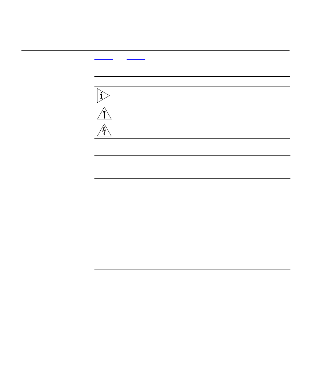
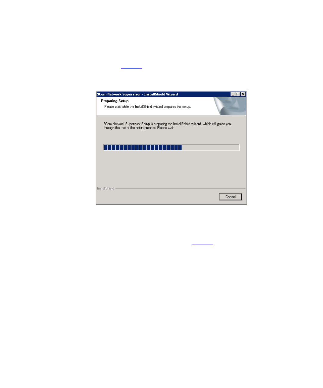
Installation Double-click your downloaded 3com_network_supervisor_v5_0.exe file
to begin the installation process. Once the installation has started (as
shown in Figure 1
Figure 1 InstallShield Wizard
), please follow the steps in the installation wizard.
Activation Once you have installed 3Com Network Supervisor, you will have a
60-day evaluation period within which to activate your software. When
you launch 3Com Network Supervisor for the first time the Activate Now
dialog will be displayed as shown in Figure 2
:
Page 29
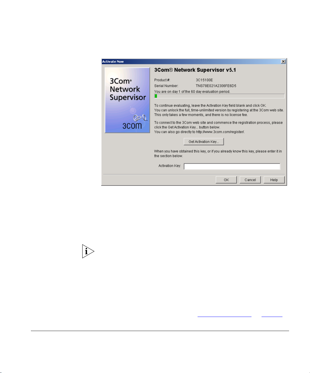
Figure 2 Activate Now Dialog
Getting Started 25
To activate your software:
1 Click Get Activation Key. 3Com Network Supervisor will direct you to a
3Com activation website to retrieve your activation key.
2 Once you have your activation key, enter it into the Activation Key text
box and click OK to complete the activation process.
If you are upgrading to Network Supervisor v5.1 from an activated copy
of Network Supervisor v5.0, you will not need to reactivate Network
Supervisor following the upgrade. Network Supervisor v5.1 will retain the
activated status from your existing installation.
However, if you are upgrading from an earlier version of Network
Supervisor, you will have to reactivate Network Supervisor following the
upgrade.
For more information, please refer to “
Product Activation” on page 33.
Getting Started This section details the operations you need to perform before you can
start using 3Com Network Supervisor with your 3Com devices.
Page 30

26 CHAPTER 1: GETTING STARTED
When you first run 3Com Network Supervisor, a Welcome dialog is
displayed which enables you to:
■ Create a new network map
■ Open an existing map
■ Open the last map you were using
Creating a New
Network Map
To create a new map, select Create a new network map and click OK to
launch the Network Discovery wizard. Follow the steps in the wizard to
initiate discovery of your network as follows:
Discovery Type Step
You can choose whether you want to:
■ Discover your local IP subnet
■ Discover all subnets connected to your default router
■ Discover one or more specific routers
Specify Subnets Step
If you have chosen to discover specific subnets, enter their details here.
Monitor Core Devices and Links Step
You can choose whether you want 3Com Network Supervisor to monitor
the status of your network after it has been discovered. If you select No,
you can enable monitoring at any time after discovery is complete.
Community Strings Step
You can enter any non-default SNMP community strings used by your
network devices. 3Com Network Supervisor needs to read SNMP
information from your network devices in order to successfully create
your network map. 3Com Network Supervisor also needs to write to
some devices in order to determine network topology accurately.
NBX Voice Network Step
Select Yes, if you have a 3Com NBX voice solution on your network.
Page 31

Getting Started 27
NBX Call Processors Step
Enter the details for any NBX Call Processors on your network. 3Com
Network Supervisor needs to read HTML information from your NBX Call
Processors in order to accurately discover and represent telephony
equipment on your network.
Summary Step
Use this step to check that all the options you have selected are correct.
Coexistence with
other Network
Management
Applications
For detailed help in stepping through the wizard, see “
The Network
Discovery Wizard” on page 75.
Click Finish to initiate your network discovery. For detailed help in
understanding the steps that 3Com Network Supervisor goes through to
discover your network see “
on page 87
.
The Network Discovery Progress Dialog Box”
The Network Discovery Summary dialog box is automatically displayed
when the discovery process is complete. Click OK to view your network
map or any of the four View Report... buttons for more information on
the network discovery operation.
The Network Changes Report button is only displayed when it is
applicable, so often there will only be three buttons visible.
Network Discovery Summary dialog box” on page 88 for more
See “
information on the reports that 3Com Network Supervisor generates on a
network discovery.
Now that you have discovered your network, you can use 3Com Network
Supervisor to monitor and manage your network devices.
You cannot install 3Com Network Supervisor on a PC which has 3Com
Network Director or 3Com Network Administrator installed. If you
already have either of these applications installed on your PC, please
uninstall them before installing 3Com Network Supervisor, or install
3Com Network Supervisor on a different PC.
Page 32

28 CHAPTER 1: GETTING STARTED
Upgrading from
earlier versions of
3Com Network
Supervisor
3Com Network Supervisor v5.1 can be installed over 3Com Network
Supervisor v5.0, and all files will be upgraded for use with 3Com Network
Supervisor v5.1.
3Com Network Supervisor v5.1 can be installed over earlier versions of
3Com Network Supervisor, and all files will be upgraded for use with
3Com Network Supervisor v5.1, but with the following restrictions:
■ All stress monitoring will initially be disabled
■ Any manually disabled stress monitors will be re-enabled
■ Any manually adjusted thresholds will be reset to default values
■ All alert attachments will be removed from devices and links (the alert
templates themselves will be preserved)
■ Information shown in the Properties dialog against a device or link
may be incomplete
■ Saved event logs from earlier versions of 3Com Network Supervisor
("<Mapname Events>.mdb" files) are not compatible with 3Com
Network Supervisor v5.0. 3Com Network Supervisor v5.0 uses a new
event log file format and file extension ("<Mapname> Events.edb").
When you load maps saved using earlier versions of 3Com Network
Supervisor into v5.0, the event log will initially be empty.
To avoid these problems, it is strongly recommended that you rediscover
your network using 3Com Network Supervisor v5.1.
If you save an upgraded map from within 3Com Network Supervisor
v5.1, you will be unable to subsequently load it back into an older version
of 3Com Network Supervisor.
3Com Network Supervisor v5.1 can be used to upgrade from:
■ 3Com Network Supervisor v5.0 (any Service Pack level) - with no
restrictions
■ 3Com Network Supervisor v4.0 (any Service Pack level) - but with the
restrictions listed above
■ 3Com Network Supervisor v3.5 (any Service Pack level) - but with the
restrictions listed above
Older versions of 3Com Network Supervisor are not supported.
Page 33

Main Features 29
After you upgrade to 3Com Network Supervisor v5.1, do not attempt to
reinstall any Service Packs that you may have downloaded for your older
version of 3Com Network Supervisor. 3Com Network Supervisor v5.1
includes all functionality and bugfixes present in Service Packs for older
versions of 3Com Network Supervisor.
Advanced Package compatibility
3Com Network Supervisor v5.1 is not compatible with Advanced Package
v1.0 or Advanced Package v2.0. If you upgrade from an installed
Advanced Package to 3Com Network Supervisor v5.1, you will lose your
Advanced Package features.
If you have Advanced Package v1.0 or v2.0, 3Com strongly recommends
that you upgrade to 3Com Network Director, which offers all the features
contained in your Advanced Package, and much more. A discount is
available for registered owners of Advanced Package v2.0 who wish to
upgrade to 3Com Network Director. For more information please visit
http://www.3Com.com/3ndupgrade.
Main Features This section outlines the main features in 3Com Network Supervisor, with
references to the relevant chapters where each feature is described in
more detail.
Main Window The map and tree within the Main Window provide the main interface for
viewing and managing your network. You can choose to view your
network in several different ways, show the current health of monitored
devices and links within your network and act as a launching point for
many of the tools available within 3Com Network Supervisor. The Main
Window also contains the main menu, toolbar and status bar of 3Com
Network Supervisor.
For more information, see “
Network Discovery The Network Discovery process allows 3Com Network Supervisor to
discover, topologise and map all devices in your network. Using the
Network Discovery wizard, you can specify exactly which parts of your
network you want to discover.
For more information, see “
Main Window” on page 39.
Discovering the Network” on page 57.
Page 34

30 CHAPTER 1: GETTING STARTED
Network Monitoring 3Com Network Supervisor can actively or passively monitor your network
for abnormal conditions which may indicate problems and will alert you
when a problem is detected.
You can also provide control over exactly how 3Com Network Supervisor
monitors your network and over what conditions should cause an event
to be logged.
For more information, see “
Monitoring the Network” on page 211.
The Event System The 3Com Network Supervisor Event System provides a constantly
updated log of activity on your network and can be used to view and
take action on abnormal network conditions before they cause problems.
The event system offers filtering tools to allow you to view only events of
interest.
For more information, see “
The Event Log” on page 233.
Traffic Prioritization Many 3Com devices have traffic prioritization (or quality of service)
features. 3Com Network Supervisor provides the Prioritize Network Traffic
Wizard to simplify the configuration of these devices. Using the wizard,
you can choose to prioritize or block specific servers or traffic types. To
provide an end-to-end quality of service, your configuration can be
applied to all supported 3Com devices.
For more information, see “
Prioritizing Network Traffic” on page 327.
Reporting The Reporting facility enables you to retrieve stored information about
your 3Com devices. Many of the features in 3Com Network Supervisor
have their own reports but there are other, general purpose reports which
give you different views of your 3Com devices. You can also create your
own reports using the Custom Report facility.
For more information, see “
Creating Reports” on page 289.
Live Update The Live Update feature keeps your copy of 3Com Network Supervisor
up-to-date with the latest device support and fixes. You can view and
download updates specifically for your copy of 3Com Network
Supervisor. In addition, 3Com Product News is also available from Live
Update to keep you informed with what is happening at 3Com.
Page 35

For more information, see “Live Update” on page 387.
Main Features 31
Page 36

32 CHAPTER 1: GETTING STARTED
Page 37

PRODUCT ACTIVATION
2
Introduction 3Com Network Supervisor uses an activation system which allows you to
use your copy of the software beyond the evaluation period. This chapter
describes how to activate 3Com Network Supervisor.
Once you have installed 3Com Network Supervisor, you can use it for an
evaluation period of up to 60 days without activating it. During this time,
you have the opportunity to activate the product each time you launch it.
It is important that you activate 3Com Network Supervisor. This removes
the evaluation period and allows you unrestricted access to the product.
Activation also starts the product’s warranty period, entitling you to
customer support for 3Com Network Supervisor for the duration of the
warranty. You can also decide to receive important update information
relating to both this and other associated products.
If you are upgrading to Network Supervisor v5.1 from an activated copy
of Network Supervisor v5.0, you will not need to reactivate Network
Supervisor following the upgrade. Network Supervisor v5.1 will retain the
activated status from your existing installation.
However, if you are upgrading from an earlier version of Network
Supervisor, you will have to reactivate Network Supervisor following the
upgrade.
This chapter covers the following topics:
■ Key Concepts
■ Components
■ Examples
■ Useful Information and References
■ Key Considerations
Page 38

34 CHAPTER 2: PRODUCT ACTIVATION
Key Concepts 3Com Network Supervisor uses the following information in the
activation process:
■ The Serial Number — 3Com Network Supervisor automatically
generates this number when it is first installed.
■ The Product Number — the part number of your software, which
starts with ‘3C’.
The part number for 3Com Network Supervisor v5.1 is 3C15100E.
■ The Activation Key — the key returned from the 3Com registration
site. Type this key into the Activate Now dialog to complete the
activation process.
3Com Network Supervisor provides an Activate Now dialog which allows
you to activate the product.
Components The following section describes how to activate 3Com Network
Supervisor.
About Dialog 3Com Network Supervisor’s About dialog is used to display general
information relating to the product, such as the name, product number,
serial number and activation state.
You can launch the About dialog by selecting the menu option Help >
About 3Com Network Supervisor.
Activate Now dialog The Activate Now dialog allows you to activate 3Com Network
Supervisor. The dialog can be launched by clicking Help > Activate Now
from the top level menu.
When the evaluation period has expired, most menu options are
disabled. However, you can still activate the product using the Help >
Activate Now menu option.
The dialog already knows the product number and serial number so you
do not need to type them in.
To obtain the activation key for this copy of 3Com Network Supervisor,
click Get Activation Key. This launches your default web browser, which
displays the 3Com registration web site.
Page 39

Components 35
3Com Network Supervisor sends the serial number and product number
for you. Follow the instructions on the web site to complete the product
registration process.
Once registration is complete, the web site displays your activation key.
You will also be sent a copy of this key via e-mail.
If you prefer, you can register your product manually at:
http://www.3com.com/register
However, 3Com recommends that you use the Activate Now dialog.
Enter the activation key you receive from the 3Com web site by typing or
copying it in to the Activation Key text box and clicking OK in the Activate
Now dialog as shown in Figure 3
Figure 3 Activate Now dialog
:
Page 40

36 CHAPTER 2: PRODUCT ACTIVATION
Examples The following section provides an example of how you might use the
Activation process.
Activating 3Com Network Supervisor
You have installed 3Com Network Supervisor on your computer and you
want to activate it.
1 Start 3Com Network Supervisor. The Activate Now dialog will appear,
showing the number of days remaining in the evaluation period.
2 Click Get Activation Key. Your default web browser is launched which
automatically directs you to the 3Com registration site.
If the wizard fails to launch your web browser, you can go directly to
3Com’s registration system by opening your preferred web browser and
entering the following URL into the browser’s address bar:
http://www.3com.com/register
3 Follow the instructions on the registration site to complete the
registration of the product and obtain the activation key. 3Com will also
send you a copy of your activation key via e-mail.
Useful Information and References
4 Enter the activation key in the Activation Key text box to activate the
product.
The following section provides useful information and references when
activating 3Com Network Supervisor.
Where can I find the product number for 3Com Network
Supervisor?
The product number for 3Com Network Supervisor is found on the
product’s packaging and is also displayed in the About 3Com Network
Supervisor dialog. To launch the About dialog, select Help > About 3Com
Network Supervisor from the menu on the main window. Refer to Finding
the Product Version on page 55 for more information.
Where can I find the serial number for 3Com Network Supervisor?
The serial number for your copy of 3Com Network Supervisor is displayed
in the About 3Com Network Supervisor dialog. Refer to F
inding the Serial
Number and Activation Key on page 56 for more information.
Page 41

Key Considerations 37
Key Considerations The following section contains troubleshooting information when
activating 3Com Network Supervisor.
What if I lose my Activation Key after registration?
You can re-register your copy of 3Com Network Supervisor to obtain your
activation key again. You will also receive an e-mail confirmation of your
activation key.
When you are re-registering the product, it is very important to enter
exactly the same user and product information during the original
registration. This includes the username, product number and serial
number. Entering different information may result in the registration
begin rejected.
If I re-install the product after it has been activated, do I need to
activate it again?
No - the product activation information is stored on your computer and
will remain intact following de-installation and re-installation.
If I upgrade to Network Supervisor v5.1 from an earlier, activated
version of Network Supervisor, do I need to activate it again?
If you upgrade from Network Supervisor v5.0, you will not need to
activate Network Supervisor again - Network Supervisor v5.1 will retain
the activated status from your existing v5.0 installation.
If you upgrade from Network Supervisor v4.0 or earlier, you will need to
activate Network Supervisor v5.1.
Why can’t I log in to the 3Com support web site?
If you experience difficulties logging in to the 3Com support web site,
please check your web browser settings to ensure that cookies are
enabled. You may also want to check with your system administrator that
your site’s firewall settings permit web site cookies.
Page 42

38 CHAPTER 2: PRODUCT ACTIVATION
Page 43

MAIN WINDOW
3
Overview This chapter describes the 3Com Network Supervisor main window. The
main window provides access to all of the features in 3Com Network
Supervisor.
This chapter covers the following topics:
■ Key Concepts
■ Components
■ Examples
Page 44

40 CHAPTER 3: MAIN WINDOW
Key Concepts This section describes some 3Com Network Supervisor key concepts
relating to the main window.
Map Files 3Com Network Supervisor stores device and topology information in map
files. Map files have the file extension
Only one map file may be open at any one time. Opening a new map file
will close the current map file.
Two other types of files are saved alongside map files. These files use the
same name as the map file but have
extensions. These files are used internally by 3Com Network Supervisor.
Although the presence of these files is not required to successfully load a
map file, previously logged event information will not be available if the
former is not present and some user-defined options may not be set if the
latter is not present.
.map.
Events.mdb
and
.properties
file
Page 45

Components 41
Components The following section describes the features of the main window and
describes the operations you can perform from this window.
Map The map provides a graphical representation of the topology of your
network. The map is covered in more detail in “
on page 105
.
Tree The tree displays the devices within your network grouped by subnet and
device group. The tree, subnets and device groups are covered in more
detail in “
Working with the Map” on page 105.
Toolbar The toolbar provides access to the most commonly used map navigation
and administration tools.
Some items in the toolbar are not always applicable. When this is the
case, the toolbar button is grayed out.
Hovering the mouse cursor over a button in the toolbar causes a tooltip
for that button to be displayed. The tooltip describes the operation
associated with the button.
Working with the Map”
The operations provided by the toolbar buttons are equivalent to their
corresponding menu items. For more information see “
page 42
.
Main Menu” on
Status Bar The status bar provides detailed information about items within the map
and tree, as well as providing a location for minimized progress dialog
boxes, such as the Network Discovery Progress dialog box.
The status bar provides information on the current selection as follows:
■ For a selected map item the text displayed is:
Selected <map item type> “<map item label>”
For example, if you were to select a router that had the label test, the
text displayed would be:
Selected Router “test”
■ For a selected link the text displayed is:
Selected Link from <map item type> ”<map item label>” to
<map item type> ”<map item label>”
Page 46

42 CHAPTER 3: MAIN WINDOW
Main Menu The following tables list each menu item for a given main menu and the
File Ta bl e 3 lists each menu item for the File menu and the associated
For example, if you were to select a link that connected a router with
the label test to a router with the label test2, the text displayed would
be:
Selected Link from Router ”test”to Router ”test2”
■ For multiple selections in the map or tree the text displayed is:
Selected Multiple Items
The status bar also provides detailed information about a menu item
when it is highlighted.
associated operation invoked by selecting it.
operation invoked by selecting it.
Tab le 3 File Menu
Menu Item Hot Key Operation
File > New Ctrl+N Creates a new empty map file and
File > Open
File > Save
File > Save As Saves the current map file using a
File > Print Ctrl+P Prints the current contents of the
Ctrl+O
Ctrl+S
launches the Network Discovery
wizard. Prompts for a save if the
current map has changed. For more
information see “Saving and Opening
Maps” on page 157.
Opens an existing map file. Prompts
for a save if the current map has
changed. See “Saving and Opening
Maps” on page 157 for more
information.
Saves the current map file. Prompts
for a filename if the map has not been
saved previously. See “Saving and
Opening Maps” on page 157 for
more information.
specified name. See “
Opening Maps” on page 157 for
more information.
map. See on
on
page 160 for more information.
“Printing the Map”
Saving and
Page 47

Components 43
Menu Item Hot Key Operation
File > Most Recently Used File
List
File > Exit Exits 3Com Network Supervisor.
Opens the map selected from the
Most Recently Used File List.
See “Saving and Opening Maps” on
page 157
Prompts for a save if the current map
has changed. For more information
see “
page 49
for more information.
File > Exit Menu Option” on
.
Edit Ta bl e 4 lists each menu item for the Edit menu and the associated
operation invoked by selecting it.
Tab le 4 Edit Menu
Menu Item Hot Key Operation
Edit > Add Map Item Launches the Add Map Item dialog
Edit > Add Link Links the two map items currently
Edit > Delete Ctrl+Delete Deletes the selected map item or link.
Edit > Grouping > Group
Devices
Edit > Grouping > Move
Devices to Group
Edit > Grouping > Ungroup
Devices
Ctrl+G Groups the selected map items
Ctrl+M
box. This dialog box allows you to add
new devices and clouds to the map.
See “
Manually Modifying the Map
Contents” on page 154 for more
information.
selected. See “
Map” on page 156 for more
information.
See “
Deleting Items from the Map”
on page 156
together into a single logical group.
See “
Device Groups” on page 124 for
more information.
Moves the selected devices to an
existing device group. See “
Groups” on page 124 for more
information.
Ungroups the selected device group.
See “
Device Groups” on page 124 for
more information.
Linking Items in the
for more information.
Device
Page 48

44 CHAPTER 3: MAIN WINDOW
View Ta bl e 5 lists each menu item for the View menu and the associated
Menu Item Hot Key Operation
Edit > Find Ctrl+F Launches the Find dialog box. This
dialog box allows you to find items in
the map by various attributes, such as
Name, IP or MAC address. See
“
Finding Items on Your Network”on
page 145
Edit > Select All Ctrl+A Selects all map items in the currently
viewed submap. See “
in the Map and Tree” on page 133 for
more information.
Edit > Select All Core Devices Selects all core infrastructure devices
in the map. See “
the Map and Tree” on page 133 for
more information.
for more information.
Selecting Items
Selecting Items in
operation invoked by selecting it.
Tab le 5 View Menu
Menu Item Hot Key Operation
View > Show Toolbar Toggles whether the toolbar is
displayed or not. For more
information see “
Toolbar Menu Option” on page 50.
View > Show End Stations Toggles whether end stations are
displayed in the map or not. See
“
Devices” on page 112 for more
information.
View > Show Undiscovered
Subnets
View > Annotate Aggregated
Links
View > Annotate Duplex
Mode
Toggles whether undiscovered
subnets are displayed in the map or
not. See “
page 122
Toggles whether the link annotations
for aggregated links are displayed in
the map or not. See “
Annotations” on page 117 for more
information.
Toggles whether the link annotations
for link duplex modes are displayed in
the map or not. See “Physical Link
Annotations” on page 117 for more
information.
for more information.
View > Show
Undiscovered Subnets” on
Physical Link
Page 49

Components 45
Menu Item Hot Key Operation
View > Annotate Resilient
Links
View > Group Map by Subnet Toggles whether devices in the map
View > Labels > Custom
Name
View > Labels > User Name Selects the display of the User Name
View > Labels > DNS Name Selects the display of the DNS Name
View > Labels > System Name Selects the display of the System
View > Labels > IP Address Selects the display of the IP Address
View > Labels > MAC
Address
View > Relayout Map Performs an automatic relayout of the
Toggles whether the link annotations
for resilient links are displayed in the
map or not. See “
Annotations” on page 117 for more
information.
are grouped by subnet or not. See
“
The Grouped Network View ” on
page 110
Network View ” on page 112 for
more information.
Selects the display of the Custom
Name label for map items in the tree
and map. See “Map Item Labels and
Address Translation” on page 128 for
more information.
label for map items in the tree and
map. See “
Address Translation” on page 128 for
more information.
label for map items in the tree and
map. See “Map Item Labels and
Address Translation” on page 128 for
more information.
Name label for map items in the tree
and map. See “Map Item Labels and
Address Translation” on page 128 for
more information.
label for map items in the tree and
map. See “
Address Translation” on page 128 for
more information.
Selects the display of the MAC
Address label for map items in the
tree and map. See “Map Item Labels
and Address Translation” on
page 128
map items in the currently viewed
submap. See “Automatic Relayout of
Maps” on page 153 for more
information.
and “The Ungrouped
for more information.
Physical Link
Map Item Labels and
Map Item Labels and
Page 50

46 CHAPTER 3: MAIN WINDOW
Menu Item Hot Key Operation
View > Go Up Ctrl+Up Navigates to the parent submap of the
currently visible submap when you are
viewing the devices in your network
grouped by subnet. See “
on page 135
View > Enter Submap Ctrl+Down Navigates to the submap associated
with the currently selected subnet or
device group. See “
page 135
View > Zoom > Zoom in Ctrl+Page
Down
View > Zoom > Zoom out Ctrl+Page UpZooms out from the map. See
View > Zoom > Fit to page Centers the map on the display and
Zooms in towards the map, centering
the current selection in the display if
applicable. See “
page 135
“
Navigation” on page 135 for more
information.
zooms in or out as necessary so that
the entire map is visible in the display.
See “
more information.
for more information.
for more information.
Navigation” on
for more information.
Navigation” on page 135 for
Navigation”
Navigation” on
Device Ta bl e 6 lists each menu item for the Device menu and the associated
operation invoked by selecting it.
Tab le 6 Device Menu
Menu Item Hot Key Operation
Device > Web Management Launches the web interface for the
selected device. See
“Web
Management” on page 307 for
more information.
Device > Telnet Management Launches the Telnet management
interface for the selected device. See
“
Telnet Management”on page 308
for more information.
Device > Administration >
Network Jack Configuration
Device > Properties Launches the Properties dialog box for
Launches 3Com Network Jack
Configuration Manager for the
selected device. See “
Configuration Manager” on page 308
for more information.
the selected items. See “
Device Details” on page 177 for more
information.
Network Jack
Viewing
Page 51

Components 47
Monitoring Ta bl e 7 lists each menu item for the Monitoring menu and the associated
operation invoked by selecting it.
Tab le 7 Monitoring Menu
Menu Item Hot Key Operation
Monitoring > Start
Monitoring
Monitoring > Stop
Monitoring
Monitoring > What’s Wrong Launches, or brings to the front, an
Monitoring > Live Graphs Launches the Live Graphs window for
Starts the monitoring of the selected
items by 3Com Network Supervisor.
See “Starting and Stopping
Monitoring” on page 225 for more
information.
Stops the monitoring of the selected
items by 3Com Network Supervisor.
See “
Starting and Stopping
Monitoring” on page 225 for more
information.
instance of the Events window filtered
to show unresolved events for the
selected items only. See “
Unresolved Events for a Selection:” on
page 240
the selected item. See “
Menu” on page 222 for more
information.
for more information.
Viewing
Live Graphs
Page 52

48 CHAPTER 3: MAIN WINDOW
Alerts/Events Ta bl e 8 lists each menu item for the Alerts/Events menu and the
associated operation invoked by selecting it.
Tab le 8 Alerts/Events Menu
Menu Item Hot Key Operation
Alerts/Events > View Filtered
Events
Alerts/Events > All Events Launches, or brings to the front, an
Alerts/Events > Configure
Alerts for Selected Items
Launches, or brings to the front, an
instance of the Events window,
filtered to show events for the
selected items only. See “
Components” on page 239 for more
information.
unfiltered instance of the Events
window. See “Events List
Components” on page 239 for more
information.
Launches the Configure Alerts dialog
box for the selected items. See
Events List
“Configure Alerts Dialog Box”
on
page 269 for more information.
Alerts/Events > Configure
Global Alerts
Launches the Configure Global Alerts
dialog box for the selected items. See
“Configure Global Alerts Dialog Box”
on
page 271 for more information.
Tools Ta bl e 9 lists each menu item for the Tools menu and the associated
operation invoked by selecting it.
Tab le 9 Tools Menu
Menu Item Hot Key Operation
Tools > Reports Launches the Reports dialog box. See
Tools > Network Discovery Launches the Network Discovery
Tools > Trace Path Ctrl+T Launches the Trace Path toolbar to
Reports Dialog Box” on page 293 for
“
more information.
wizard for the selected subnets. See
“The Network Discovery Wizard” on
page 75
show the possible physical paths
between the two selected devices, or
launches the Trace Path wizard if two
devices are not selected. See “
Path” on page 141 for more
information.
for more information.
Trace
Page 53

Components 49
Menu Item Hot Key Operation
Tools > Prioritize Network
Traffic
Tools > Live Update Launches the Live Update wizard. See
Tools > Device Warranty Ctrl+W Launches the Device Warranty wizard.
Tools > Options Launches the Options dialog box. See
Launches the Prioritize Network Traffic
wizard for the selected devices. See
“
Prioritize Network Traffic Wizard” on
page 335
Live Update Setup Wizard” on
“
page 389
See “
page 313
“
Tools > Options Menu Option” on
page 50
for more information.
for more information.
Device Warranty Wizard” on
for more information.
for more information.
Help Ta bl e 10 lists each menu item for the Help menu and the associated
operation invoked by selecting it.
Table 10 Help Menu
Menu Item Hot Key Operation
Help > Contents and Index Launches the online help. For more
information see “
Index Menu Option” on page 54.
Help > Launch User Guide Launches the user guide. For more
information see
Help > Contents and
“Help > Launch
User Guide” on page 55
Help > Activate Now Launches the Activation dialog box.
Help > About 3Com Network
Supervisor
For more information see “
Now dialog” on page 34.
Launches the About 3Com Network
Supervisor dialog box. For more
information see “
Network Supervisor Menu Option” on
Help > About 3Com
Activate
page 55.
File > Exit Menu
Option
This operation closes 3Com Network Supervisor. The following message
will be displayed if there are outstanding changes to the map that need
to be saved:
Page 54

50 CHAPTER 3: MAIN WINDOW
Figure 4 Exit Before Save Dialog Box
View > Show Toolbar
Menu Option
> Options Menu
Tools
Option
This menu item toggles between a visible or hidden toolbar. If you find
you do not use the toolbar, hiding it provides more space for the map and
tree.
This menu item launches the Options dialog box, which is used to
configure the default behavior of 3Com Network Supervisor. The Options
dialog box consists of the following tabs:
■ General — default file locations and how the application should
behave.
■ Device Management — options for managing devices in your map.
■ Internet — how 3Com Network Supervisor should connect to the
Internet.
■ Alerts — options to launch alerts when events are resolved.
Any option set in the Options dialog box applies to all maps opened
within 3Com Network Supervisor, not just the map that was open when
the option was set. All options are automatically saved, and are retained
for future use in 3Com Network Supervisor.
General
This tab, as shown in Figure 5
, displays the following:
■ Default File Location — change the default location where map files
are saved to a different location. Click Browse to choose the directory
you want. If the path you enter does not exist, you are warned of this
when you click OK.
The default directory is:
dir>\maps\my_maps
Saving and Opening Maps” on page 157 for more information.
See “
< 3Com Network Supervisor install
.
Page 55

Figure 5 General Tab
Components 51
■ MAC Addresses — for any MAC address displayed, you can append
the manufacturer’s name to the start by enabling the Translate MACs
option. For example, 08-00-8F-xx-xx-xx becomes 3Com-xx-xx-xx. This
option is disabled by default. See “
Vendor Translation of MAC
Addresses” on page 130 for more information.
■ Show the Live Update Setup Wizard next time — this option is
enabled by default, See “
Live Update Setup Wizard” on page 389 for
more information.
■ Show the Device Warranty dialog box after a refresh operation
— this is enabled by default. See “
page 312
■ Auto-expand product information banner on toolbar - this is
for more information.
Device Warranty Dialog Box” on
enabled by default. Unchecking this option will prevent the product
information banner on the toolbar from expanding when you hover
the mouse over it.
Page 56

52 CHAPTER 3: MAIN WINDOW
Device Management
This tab allows you to change the management application that is
launched when a device is double clicked in the list as shown in Figure 6.
Figure 6 Device Management Tab
Choose from Web Management, which is the default, Telne t
Management or Administration Application. If a device does not support
the preferred Web Management application, Teln et is launched instead.
For further information on the Device Management options see
Configuring Single Devices” on page 307.
“
Page 57

Components 53
Internet
This tab, as shown in Figure 7
■ Use Web browser settings — this is the default option. If your web
, allows you to set the following options:
browser uses a proxy server to access the Internet, 3Com Network
Supervisor will use the same system.
Figure 7 Internet Tab
■ Direct connection to the Internet — use this option if your
management station connects to the Internet directly through a Local
Area Network, without using a proxy server.
■ Custom proxy settings — specify the address of the proxy server
followed by the proxy port number. If your proxy server requires
authentication click the My proxy server requires authentication
checkbox and enter the username and password.
Live Update” on page 387 for more information.
See “
Page 58

54 CHAPTER 3: MAIN WINDOW
Alerts This tab, as shown in “Alerts Tab”, allows you to specify whether 3Com
Network Supervisor should launch alerts for resolved events.
Figure 8 Alerts Tab
Help > Contents and
Index Menu Option
For further information, see “
Launching Alerts When Events are
Resolved” on page 275
This launches the Contents and Index pages of the online help.
The 3Com Network Supervisor online help system is a browser-based
help system, and uses the default browser for displaying help. If you do
not have a default browser configured on your system then 3Com
Network Supervisor will be unable to launch the online help system.
Page 59

Examples 55
Help > Launch User
Guide
Help > About 3Com
Network Supervisor
Menu Option
Examples
Finding the Product
Version
This launches the 3Com Network Supervisor User Guide.
You must have a suitable PDF reader correctly installed on your PC in
order to launch the user guide.
When you launch 3Com Network Supervisor for the first time, the About
dialog box is displayed.
The dialog box shows the product name, product number, serial number
and the major version number. Any service packs installed are also listed.
You have a query about an aspect of 3Com Network Supervisor
functionality and want to contact 3Com support. The support engineer
asks you for your 3Com Network Supervisor product version.
®
1 Launch the About dialog box using Help > About 3Com
Network
Supervisor:
Figure 9 About Dialog Box
2 The product version number and service pack level are listed in the first
line of the dialog box.
Page 60

56 CHAPTER 3: MAIN WINDOW
Finding the Serial
Number and
Activation Key
You have a query about an aspect of 3Com Network Supervisor
functionality and contact 3Com support. The support engineer asks you
for your 3Com Network Supervisor serial number and activation key.
®
1 Launch the About dialog box using Help > About 3Com
Network
Supervisor:
2 The serial number is located on the second line of the dialog box.
3 The activation key is located on the third line of the dialog box.
If you have not yet entered the activation key then the About dialog box
will not display them, but will instead show the remaining evaluation
period.
Page 61

DISCOVERING THE NETWORK
4
Overview This chapter describes how 3Com Network Supervisor discovers
information about your network.
Before you can use 3Com Network Supervisor to manage your network
you must instruct it to perform a network discovery. This chapter explains
the discovery process, and how to tailor it to work best on your network.
It also describes any problems you may encounter with the discovery
process and the steps you can take to overcome them.
This chapter covers the following topics:
■ Key Concepts
■ Components
■ Examples
■ Useful Information and References
■ Discovery Report Errors and Warnings
Page 62

58 CHAPTER 4: DISCOVERING THE NETWORK
Key Concepts The discovery process can be initiated in a number of ways detailed later
in this chapter. This section explains the key concepts behind the
discovery process itself.
The process is divided into two distinct operations – detecting the devices
that exist on the network (discovering devices), and subsequently
establishing how they are physically connected together (determining
topology). Both of these operations are divided further into several
stages. The main concepts associated with these operations and
associated stages are outlined in this section as follows:
■ How 3Com Network Supervisor discovers devices on the network
■ How 3Com Network Supervisor determines the network topology
■ How 3Com Network Supervisor re-discovers information about a
network it already knows about
The Discovery Process
– Detecting Devices
This operation determines which devices exist on one or more IP subnets.
It also finds out more about each discovered device, such as its type and
capabilities. The operation is initiated with a list of subnets to discover.
Within each subnet 3Com Network Supervisor attempts to locate devices
across one or more specific IP ranges. You can control the ranges of
devices to be detected within each subnet, but the default behavior is to
attempt the full range for each subnet. Fine-tuning the discovery process,
including specifying subnet ranges, is described later in this chapter.
The detecting devices part of the discovery process consists of a number
of discrete stages:
P Ping
1 I
evice Capability Detection
2 D
3 SNMP Type Detection
4 IP to MAC Resolution
5 End Station Type Recognition
6 Web Type Recognition
7 DNS Name Resolution
BX Phone Detection
8 N
9 Device Sizing
Page 63

Key Concepts 59
With the exception of the sizing stage (explained below), each of the
stages runs sequentially, and the sequence is repeated for each subnet
that is being discovered. The sizing stage runs once only, when all the
other stages have been executed for all of the subnets being discovered.
The purpose of each stage is described below:
IP Ping
In order to detect which IP nodes exist, this stage performs an IP Ping over
the specified ranges of addresses for the subnet. If no ranges are
specified, a default range is deduced from the subnet address and subnet
mask of the subnet being discovered. This range excludes the subnet
address itself (lowest address value) and the subnet broadcast address
(highest address value).
Device Capability Detection
This stage is applied to each device that responded to a ping in the
previous stage. Its purpose is to determine if a device supports certain
network protocols. Specifically, these are:
■ SNMP
■ HTTP
■ Tel ne t
The most detailed information is generally obtained from devices that
support SNMP. For these devices 3Com Network Supervisor initially starts
the communication using the read community string as originally
specified in the Network Discovery wizard. Having successfully
communicated using the read community string it then attempts
communication using the write community string(s), again obtained from
the Network Discovery wizard. While the write community string is not
heavily used by the discovery process (except a small part of topology), it
is used extensively by other features of 3Com Network Supervisor.
Consequently, if the write community cannot be successfully determined,
discovery will continue, but add a warning to the report provided at the
end of discovery.
Page 64

60 CHAPTER 4: DISCOVERING THE NETWORK
3Com Network Supervisor detects HTTP and Telnet capabilities by
attempting to open a TCP connection to the device using ports 80 and 23
respectively. The purpose of this detection is to decide whether to enable
the Web and Telnet menu options on the right-click menu. For certain
3Com devices additional information can be obtained using HTTP – see
Web Type Recognition” and “NBX Phone Detection” on page 61
“
SNMP Type Detection
This stage only applies to devices that were found to support SNMP
during the Device Capability Stage. 3Com Network Supervisor reads
standard SNMP MIBs in order to determine additional information about
each SNMP node, in particular the type of the device (based on MIB-II
sysObjectID), its IP addresses and its MAC addresses. Where a device has
multiple IP addresses that respond with the same information, e.g. list of
MAC addresses, 3Com Network Supervisor ensures that it is represented
as a single device on the map. Certain devices which have multiple IP
addresses respond with different information. Initially they are detected
as separate nodes, which 3Com Network Supervisor attempts to resolve
in the sizing stage.
If a router is detected when discovering a given subnet, that router
information will be made available to any subsequent subnets included as
part of the whole discovery operation. This ensures that the router is not
interrogated more than once for the same information by several stages.
IP to MAC Resolution
This stage is responsible for obtaining the MAC addresses of non-SNMP
nodes. For the local subnet, i.e. the one to which the 3Com Network
Supervisor PC is attached, this is achieved by reading the ARP cache of
the 3Com Network Supervisor PC. For remote subnets this is achieved by
querying any routers that have been discovered on these subnets. This
stage is not normally required for determining the MAC addresses of
SNMP nodes, since that can be achieved in the SNMP type detection
stage.
It is important for 3Com Network Supervisor to determine the MAC
addresses of nodes in order to be able to subsequently determine their
position in the network topology.
End Station Type Recognition
This stage is responsible for attempting to determine the operating
system type for devices that are IP-only or unrecognized (generic) SNMP.
Page 65

Key Concepts 61
The end station stage attempts to determine an end station’s type by
performing the following steps:
1 Attempting to start a Telnet session with the device and subsequently
parse the Login banner if the Telnet service is supported.
2 Determining if the node is operating as a file server. This is achieved by
attempting to connect to the device via TCP port 2049.
3 Determining if the node is operating as a print server. This is achieved by
attempting to connect to the device via TCP port 515.
4 Using Microsoft Windows API calls to obtain the Windows operating
system information, provided the node is a member of
domain/workgroup.
Web Type Recognition
Certain 3Com devices have Web (HTTP) management interfaces but do
not support SNMP. Some of these devices identify their type using a
hidden tag in their home page. For devices that have been recognized as
supporting HTTP but not supporting SNMP, 3Com Network Supervisor
looks for this tag in order to recognize the device.
DNS Name Resolution
During this stage 3Com Network Supervisor attempts to retrieve a DNS
name for each IP address that has been detected. 3Com Network
Supervisor uses information from the Windows registry in order to
establish potential DNS servers that exist. It then communicates with
them directly making DNS queries using UDP.
NBX Phone Detection
This stage obtains detailed information about any Network Branch
eXchange (NBX) devices that were discovered as part of the Web Type
Recognition Stage.
The Network Discovery wizard allows you to specify the IP addresses of
individual NBX call processors (NCPs) on the network, and a separate
username/password for each.
Page 66

62 CHAPTER 4: DISCOVERING THE NETWORK
This stage is required because the NBX chassis and phones do not support
SNMP. Many of the phones will not have IP addresses and consequently
will not respond to a ping. The NBX chassis contains a non-visible Web
page which 3Com Network Supervisor downloads using HTTP. The page
provides 3Com Network Supervisor with a list of phones that are
associated with that NBX chassis. This allows 3Com Network Supervisor
to identify the existence of phones which would not normally be
detected.
NBX phones can be configured to work with or without an IP address.
Those with just a MAC address will be added to the 3Com Network
Supervisor map in the same subnet as the NBX chassis, i.e. the subnet
currently being discovered. Those phones that additionally have an IP
address are only added to the map if the subnet they belong to is
discovered as part of the current discovery operation.
Device Sizing
During this final discovery stage further details are obtained about
individual SNMP devices that have been discovered. This is done for
devices which 3Com Network Supervisor knows how to interrogate
further, often using proprietary MIBs. Sizing basically means obtaining
detailed configuration information. Normally this includes determining:
the number of units in a stack or number of modules in a chassis, their
type and software version, the number and type of ports on each unit or
module and their link status, the VLANs configured on the device.
This stage is executed once only when all the other stages have been run
on all of the desired subnets. The reason for this is that during the other
discovery stages some IP addresses may have been discovered as separate
devices, but it is desirable for 3Com Network Supervisor to display them
as a single device on the map. Typically this applies to devices, with their
own IP addresses, that can contain intelligent modules, also with their
own IP addresses. In particular this applies to routing modules, since they
tend to have IP addresses on subnets not known to the host device
chassis or stack. By communicating with the chassis and its intelligent
modules, 3Com Network Supervisor can deduce that they are physically
part of the same chassis, and consequently merge them into a single
device on the map.
Page 67

Key Concepts 63
The Discovery Process
– Determining
Topology
The second part of the discovery process is to determine the topology of
a network, by establishing what links exist between the different devices
that have been discovered. The operation determines how the devices
discovered by the previous detecting devices operation are physically
connected together.
The topology process starts when all discovery operations have
completed. The topology process is applied to one subnet (or more
specifically multinet) at a time.
3Com Network Supervisor uses the term multinet to describe a situation
where more than one subnet is attached to a single router port. This can
result in devices on different subnets sharing the same switched
infrastructure. Consequently, although devices may logically be on
different subnets they may learn the MAC addresses of the devices on the
other subnet(s) in their bridge tables. Switches learning the MAC
addresses of other switches is an important concept in determining the
network topology.
The topology algorithm uses Bridge Forwarding Database (FDB) tables to
determine on which ports a switch has learned the MAC addresses of
other switches in the network. It uses the information of switch ports that
have learned the addresses of other switches in order to build a tree of
network devices representing the physical connectivity. In reality, each
subnet/multinet may not physically appear to be a tree, for instance if
spanning tree is used to employ resilient paths. The algorithm used to
deduce the topology takes such scenarios into consideration.
Before the tree-building process can take place 3Com Network Supervisor
needs to obtain the list of learned addresses for each switch. In practice
this involves more than just reading the FDB tables, as different device
types have different port and unit numbering schemes. For efficiency
purposes an initial attempt is made to determine the positions of most of
the end stations. This is done by checking for ports that have only learned
the address of a single device that is not a switch. Because the positions
of many end stations are resolved here, the amount of information
required to be read from the switches is reduced. A summary of the main
topology stages is given below.
Unlike the discovery stages described in the previous section these stages
are all represented on a single progress bar in the Network Discovery
Progress dialog box.
Page 68

64 CHAPTER 4: DISCOVERING THE NETWORK
Sizing stage
This stage determines the units and ports that belong to each switch. It
establishes which ports have a link present so that it knows which ports
to consider during topology. Since the detecting devices operation has
already sized each device, it does not need to communicate with the
devices again.
Information obtained from the devices is also used to establish whether
they are supported by 3Com Network Supervisor. For instance, it checks
the agent version along with other parameters. Warnings are logged in
the Discovery report. For non-3Com devices an attempt is made to use
standard MIBs when considering them as part of the topology process.
Since different devices use differing numbering schemes for units and
ports and often use proprietary MIBs, the information displayed about
the topology of third party devices will not be as detailed as that of 3Com
ones, and sometimes may not be as accurate.
Spanning Tree stage
Having obtained a list of supported switches,
determine those whose spanning tree links are blocked. This information
is generally provided by standard bridge MIBs. This is an extension of the
Device Sizing stage, but the information obtained is only required for
topology.
this stage attempts to
The ports participating in such links are eliminated from the remainder of
the topology process until the tree-building stage.
Remote Poll Stage (broadcast ARP)
The purpose of this stage is to attempt to force each switch to learn the
addresses of other switches on the same subnet/multinet. It uses remote
poll to instruct each switch to ping an unused address on the subnet,
thus forcing it to transmit a broadcast ARP. This causes other switches on
the subnet to learn the addresses of the source switch.
Remote Poll, sometimes called Remote Ping, is a mechanism, using SNMP,
to instruct a device to ping another IP address. This requires an SNMP set
instruction to be sent to the device, which relies on 3Com Network
Supervisor having correctly determined the SNMP write community string
during the Device Capabilities Detection stage. If the write community
string has not been correctly established or the device does not support
the remote poll feature (e.g. third party devices) then the accuracy of the
deduced topology may be reduced.
Page 69

Key Concepts 65
Initial Endstation stage
During this stage an attempt is made to identify the ports that have only
learned a single address. This is done by reading bridge address tables.
The purpose of this stage is two-fold:
■ to eliminate the need for many end station addresses having to be
considered in the rest of the topology, which can reduce the amount
of processing and network traffic generated in the remainder of the
topology process;
■ to detect the existence of non-IP (MAC-only) nodes. If a port has a
functioning link and has learned exactly one MAC address then that
address is assumed to be a single node attached to that port. If no IP
address was found to map to this MAC address during the IP to MAC
Resolution stage then 3Com Network Supervisor will assume that this
MAC address belongs to a new node. Consequently 3Com Network
Supervisor will show the MAC-only node on the map.
You may have deliberately instructed the discovery operation to only
detect IP ranges relevant to your switches which are outside the ranges of
your endstations. Consequently the depiction of MAC-only nodes may
not be required.
Device Resolution Stage
During this stage 3Com Network Supervisor attempts to establish which
switches have learned the addresses of other switches, and on which
ports. Since some addresses have already been read from the bridge
tables in the previous stage, 3Com Network Supervisor may not need to
communicate with all switches during this stage.
At the end of this stage, 3Com Network Supervisor analyses whether it
has enough information to determine the network topology.
Remote Poll Stage (directed pings)
If insufficient information was obtained from the Device Resolution stage,
then an attempt is made to force devices to learn the addresses of others
by instructing them to ping each other (remote poll).
As with the previous remote poll stage the write community string of the
relevant switches is required. Also, as with the previous stage some
devices may not support remote poll. If either the write community string
is not known for a device or it does not support remote poll then the
accuracy of the deduced topology may be reduced.
Page 70

66 CHAPTER 4: DISCOVERING THE NETWORK
Outstanding end station stage
Not all end stations will be resolved by the Initial Endstation stage. For
instance, some ports may have multiple addresses in their bridge tables
even though only a single device is attached (if, for example, older
addresses not have aged out). Therefore a similar process to the Device
Resolution stage is used to locate the switches that have learned the
addresses of known end stations. As with the Device Resolution stage it
may not be necessary to communicate with all switches since their
address tables will have been cached from the previous stages.
Tree Building Stage
This does not require any device access. It is the point at which 3Com
Network Supervisor analyzes all the information it has obtained from the
previous stages. It builds a tree view of the subnet/multinet, placing end
station devices appropriately. It also adds back in any blocked spanning
tree links.
Clouds – Unknown Topology
When 3Com Network Supervisor builds the network tree, there may be
certain parts where it is unable to exactly determine the network
topology. In such cases you will see clouds on your map depicting the
areas of uncertainty. Typically these tend to be ports that have seen the
addresses of multiple devices, but those learned devices do not provide
any further topology information about the network.
For example, there may be a case where a switch port is connected to an
unmanaged hub, and that unmanaged hub is directly connected to two
end stations (e.g. PCs). The port on the first switch will learn the
addresses of the two end stations. It will not learn the address of the hub
(because it does not have one) and 3Com Network Supervisor will not
detect the existence of the unmanaged hub because it won’t respond to
a ping. 3Com Network Supervisor depicts this scenario as follows:
Page 71

Key Concepts 67
Figure 10 Clouds – Unknown Topology
The switch port cannot be physically connected to two end stations, and
as such 3Com Network Supervisor inserts the cloud to indicate that there
is something missing. In this case the cloud is where the unmanaged hub
should be.
A similar situation can also occur when insufficient topology information
has been obtained from one or more switches, possibly because 3Com
Network Supervisor lost communication with that switch during the
topology process. If the problem device were an edge switch that is
actually connected to many end stations, 3Com Network Supervisor
would show this as below:
Page 72

68 CHAPTER 4: DISCOVERING THE NETWORK
Figure 11 Edge Switch – Unknown Topology
You can identify which switch is the problem device here by checking if
unit and port information has been successfully retrieved for each link to
each switch. Hover the mouse over the end of the link nearest each
switch to show tooltip information on the link. The switch with missing
unit and port information is probably the cause of the problem. In the
situation above, it is clear that the bottom switch is at fault.
If information was available, the problem switch would be positioned
where the cloud is, and the cloud would not be shown. The above
situation occurs because the switch to the left of the diagram has learned
the addresses of all the end stations, and also the bottom switch.
However, because 3Com Network Supervisor lost communication with
the bottom switch, it also gets treated as if it were an end station (since
topology information could not be read from it).
Page 73

Key Concepts 69
If a problem was encountered when communicating with the switch you
should see an error in the Discovery report produced by 3Com Network
Supervisor at the end of the discovery process. Always check the
Discovery report first when your discovered network map appears to be
incorrect.
Sometimes clouds appear in the core of the network when a key, core
device has not been discovered properly:
Figure 12 Clouds – Core Device Failed to be Fully Discovered
Hover the mouse over the links to each of the Switches. If one of them
shows no unit or port details, it is likely that this switch should have been
positioned where the cloud is. If all the switches give unit and port
details, it is likely that there is another device that should be positioned
where the cloud is, but that was not detected by 3Com Network
Supervisor.
Page 74

70 CHAPTER 4: DISCOVERING THE NETWORK
Wireless Clients Clouds
Wireless client clouds are shown directly connected to a Wireless access
point on your map. They are used to indicate the number of wireless
clients connected to the access point.
The Discovery Process
– Rediscovery
When the first discovery operation is fully complete the information
3Com Network Supervisor has obtained will be displayed on the map.
You can then instruct 3Com Network Supervisor to perform additional
discoveries (rediscoveries). You may wish to do this because:
■ There are some additional subnets that you wish to see on your map
that either weren’t specified in the original discovery or didn’t exist on
your network at the time you performed the initial discovery.
■ Some new devices have been added to your existing subnets or some
of the existing devices have changed configuration.
When you perform a rediscovery on existing subnets 3Com Network
Supervisor will remember and reuse some of the options you specified on
the previous discovery, including additional community strings that you
specified and the NCPs in your network.
When 3Com Network Supervisor performs a second or additional
discovery it does not update your map as it progresses. It adds all the
information it acquires to a temporary database. This means that you can
continue to work with your current map until the new discovery
completes, though certain tasks are restricted. Although 3Com Network
Supervisor is populating the temporary database with the new
information, it does obtain some parameters from the main, working
database, for example any community strings that were successfully
determined for devices that are subsequently being rediscovered.
Once 3Com Network Supervisor completes its additional discovery it then
updates the main database (and subsequently the map) with the newly
discovered information. It does this by comparing the information that
exists in the main database with that in the new, temporary database.
The basic rules it applies, when updating the main database, are as
follows:
■ Any new subnets are simply added to the new database as they would
be on an initial discovery
■ Any new devices are simply added to the appropriate subnets (either
existing or new).
Page 75

Components 71
■ Any devices that have changed (e.g. unit added/removed) are updated
– you can view their new details using the Properties dialog box.
■ Devices that exist in the main database but have been removed from
the network and/or simply did not respond in the second discovery
will not be deleted from the database or the map. The exception to
this is if a device’s IP address now belongs to another device. For
example: device A initially has address x, device B has address y. On a
subsequent discovery device A now has both addresses x and y. In this
scenario device A’s information will be updated to reflect its new
addresses and device B will be deleted.
■ Any new links (that is, connections between devices and/or device’s
ports) detected by the topology process will be added to the relevant
devices on the map.
■ If a port previously had a link to a device and that port is subsequently
detected as being connected to a different device, the old link will be
deleted and the new one created. A port can only be connected to
one other node.
■ If a port previously had a link and the second discovery could not
successfully establish that the same port was connected (for example,
3Com Network Supervisor lost communication part way through)
then that link will not be deleted. Instead it will be marked as
unconfirmed and as a result will appear as a dashed line on the map.
Any changes detected as a result of additional discoveries are fully
described in the Changes report, automatically generated by 3Com
Network Supervisor at the end of a rediscovery operation. See “
The
Changes Report” on page 92.
Components The following section describes the features of the discovery tool and
how you can use them to tailor the discovery process to your needs. It
includes the dialogs and wizards that you can use to control the
discovery, and any appropriate reports that may be generated as a result
of a discovery operation.
You cannot launch the Network Discovery wizard while an existing
discovery operation is in progress. Instead, 3Com Network Supervisor will
simply display the Progress dialog box for that discovery.
Page 76

72 CHAPTER 4: DISCOVERING THE NETWORK
Launching a
discovery
This section describes how your instruct 3Com Network Supervisor to
start the discovery process. You can initiate network discovery from a
number of places:
■ The Welcome dialog box
■ File > New menu option
■ Too ls > Network Discovery menu option with nothing selected
■ Too ls > Network Discovery menu option with a discovered subnet
selected
■ Too ls > Network Discovery menu option with an undiscovered subnet
selected
The Welcome dialog box
When 3Com Network Supervisor is opened it displays the Welcome
dialog box:
Figure 13 Welcome Dialog Box
Page 77

Components 73
If you have not yet registered 3Com Network Supervisor and it is still in
the evaluation period, the first dialog box you see when launching the
application is the About dialog box. Closing this takes you to the
Welcome dialog box.
When you select the Create a new network map option and click OK, the
Network Discovery wizard is launched.
File > New
From the main menu, when you select the New option from the File
menu the Network Discovery wizard is launched. This is identical to
choosing Create a new network map from the Welcome dialog box.
Tools > Network Discovery with nothing selected
With no subnets selected in the tree or map, select Network Discovery
from the tools menu. The Network Discovery wizard will be launched at
the first pane Discovery Type.
Tools > Network Discovery with a discovered subnet selected
If you select one or more discovered subnets in the map or the tree and
select Network Discovery from the tools menu, the Network Discovery
wizard will be launched at the Specify Subnets pane. (See Specify Subnets
Pane on page 77.) The subnets you selected will be included in the list on
this pane:
Figure 14 Specify Subnets Pane
Page 78

74 CHAPTER 4: DISCOVERING THE NETWORK
The subnet mask and range information are also filled out. You can
modify the range information by selecting the appropriate subnet in the
list and clicking Edit. If you choose not to modify the range information
then the discovery operation will include all ranges that have currently
been added to that subnet. If you do modify the range then only the
ranges you specify will be used in the discovery operation. However, old
ranges will not be discarded, and you can still view them by launching the
properties dialog box against the subnet.
You can also start a Network Discovery by right-clicking on a discovered
subnet, and selecting Network Discovery. This has the same effect as
selecting Network Discovery from the Tools menu.
Tools > Network Discovery with an undiscovered subnet selected
If you have already performed a discovery operation, and a router was
detected during that discovery, then it is likely that you will have some
undiscovered subnets on your map. These subnets will be those to which
the router is directly attached and were not specified in the original
discovery.
Figure 15 Undiscovered Subnet
If you select one or more of these subnets in the map or the tree and
select Network Discovery from the To ol s menu, the Network Discovery
wizard will be launched at the Specify Subnets pane. As with selecting an
existing subnet, the subnet information will be included in the list. The
range information will always default to All, although you can change
this if you wish by selecting the desired subnet in the list and clicking the
Edit button.
As with selecting discovered subnets, if you select an undiscovered
subnet in the tree or the map the right-click menu contains the Network
Discovery option. Selecting this has the same effect as selecting Network
Discovery from the tools menu.
Page 79

Components 75
You can also launch the Network Discovery wizard for an undiscovered
subnet by double-clicking on its icon in the map or tree. This has the
same effect as selecting Network Discovery from the tools menu.
The Network
Discovery Wizard
This step-by-step guide takes you through the Network Discovery wizard
in order to customize the discovery process. When you complete the
wizard the discovery process will be started.
If you have previously created a network map, you can use this wizard to
rediscover all of your network, part of it, or discover a completely new
part. The discovery process verifies the devices and links on the network
map and incorporates any changes. To do this, you must open the map
before starting the wizard.
Discovery Type Pane
This is the first pane of the wizard:
Figure 16 Discovery Type Pane
Page 80

76 CHAPTER 4: DISCOVERING THE NETWORK
It allows you to specify how the list of subnets to discover is determined:
■ Local subnet – Select this radio button and click Next to discover only
the subnet to which the 3Com Network Supervisor PC is attached.
The discovery process queries the operating system to determine the
subnet mask for the local subnet. The wizard moves onto the Monitor
Core Devices and Links pane. (See M
Pane on page 82.) This means that you cannot specify IP ranges when
using this option. If you wish to specify ranges for the local subnet
discovery you will need to use the Specify Subnets option and add the
details of the local subnet to the list of subnets to discover.
■ LAN subnets connected to the default router or gateway - Select
this radio button and click Next to discover all devices on the local
subnet (to which the 3Com Network Supervisor PC is attached) and
any additional subnets that are one router hop away (but only via LAN
connections). 3Com Network Supervisor establishes which subnets are
one hop away by querying the default router. As with the Local
Subnet option it is not possible to specify the IP address ranges for the
subnets to be discovered.
■ Specify subnets – Select this radio button and click Next to specify
exactly which subnets you wish to discover and also limit the ranges of
IP addresses to discover on each subnet. Use the Specify Subnets pane
to enter the subnets you want to discover.
onitor Core Devices and Links
Page 81

Components 77
Specify Subnets Pane
This pane is shown if you chose the Specify Subnets option on the first
pane of the wizard.
Figure 17 Specify Subnets Pane
If you select one or more subnets in the tree or map view prior to
launching the Network Discovery wizard then you will be immediately
taken to this step, with the details of the subnets you selected added to
the list box.
Once you are happy with the list of subnets you have configured in the
list in the Specify Subnets pane of the wizard, and with the address
ranges associated with each, click Next to move to the next step of the
wizard.
Adding subnets to the list
To add a new subnet to the list you wish to discover, use the Add button.
This will launch the Add Subnet dialog box below:
Page 82

78 CHAPTER 4: DISCOVERING THE NETWORK
Figure 18 Add Subnet Dialog Box
You must enter at least the IP address and subnet mask into the
appropriate fields for the subnet you wish to specify.
You can use the dot ‘.’ key to move to the next segment of an address
field.
If you wish to limit the ranges of addresses that 3Com Network
Supervisor will detect for your specified subnet, you must first select the
Discover custom ranges radio button and the ranges table and Add
button will become enabled.
The Discover full range and Discover custom ranges radio buttons are
only enabled if you have entered a valid Address and Mask pair.
The ranges table lists the ranges of IP addresses that 3Com Network
Supervisor will detect for your specified subnet. To add a range to the list
of ranges to detect, use the Add button. This will launch the Add Range
dialog box below:
Page 83

Components 79
Figure 19 Add Range Dialog Box
This allows you to enter the start and end IP addresses of the range to
detect.
To discover a single IP address on a subnet, add a range with the same
start and end IP address.
An existing range can be modified by selecting the range and clicking
Edit. This will display the same dialog box as for adding subnets,
described above, with the Start and End fields completed with the
information you originally supplied. Modify the fields as necessary and
select OK to update the range.
To remove ranges from being detected, select the ranges and click Delete.
Removing discovered ranges from the list, or modifying discovered ranges
so that previously detected IP addresses will not be detected, does not
remove them from the map, but simply removes them from the list of
ranges to rediscover when the Network Discovery is started. The ranges
will remain in the map but will be unchanged by the Network Discovery
process. See “
Deleting Items from the Map” on page 156 for details of
how to remove devices permanently from the map.
Click OK to return to the Specify Subnets pane of the wizard. The subnet
you have just specified has been added to the list box. Note that if you
enter information that conflicts with a subnet already in the list, the
dialog box will report an error and will not be dismissed. For example, the
two subnets 1.2.3.0 / 255.255.255.0 and 1.2.3.192 / 255.255.255.192
cannot both exist – one is a superset of the other.
Page 84

80 CHAPTER 4: DISCOVERING THE NETWORK
Editing subnets in the list
You can modify the details of any of the subnets in the list by selecting
the item and clicking Edit. This will display the same dialog box as for
adding subnets, described above, with each of the fields completed with
the information you originally supplied. Modify the fields as necessary
and select OK to return to the wizard. 3Com Network Supervisor will not
allow you to modify the subnet if it conflicts with another one in the list.
Removing subnets from the list
Select a subnet and click Remove to remove a subnet from the list.
Removing discovered subnets from the list does not remove them from
the map, but simply removes them from the list of subnets to rediscover
when the Network Discovery is started. The subnet will remain in the
map but will be unchanged by the Network Discovery process. See
Deleting Items from the Map” on page 156 for details of how to
“
remove subnets permanently from the map.
Choosing from a list of known subnets
The Find Subnets button instructs 3Com Network Supervisor to attempt
to locate the subnets immediately neighboring your local subnet. The
located subnets are displayed in the Find Subnets pane.
Page 85

Figure 20 Find Subnets List
Components 81
Select one or more subnets from the list, and click s to add them to the
list of subnets to be rediscovered. You can then edit their range as
normal.
3Com Network Supervisor communicates with the routers on your local
subnet in order to populate the above dialog box. It uses SNMP to
communicate with the routers and consequently requires their read
community strings in order to query them. By default, it uses public. If
that is not the correct read community for any of the routers, the query
will fail and the following dialog box displays:
Page 86

82 CHAPTER 4: DISCOVERING THE NETWORK
Figure 21 Query Failure Dialog Box
If you want 3Com Network Supervisor to continue searching for subnets
using the router highlighted in this dialog box, enter the correct read
community for the router and select OK. Click Cancel to move onto the
next router.
Monitor Core Devices and Links Pane
The next step of the wizard allows you to configure how core devices will
be monitored for stress when the discovery process is complete.
The Monitor Core Devices and Links pane is displayed as follows:
Figure 22 Monitor Core Devices and Links Pane
Page 87

Components 83
If you choose the Yes radio button then monitoring of the discovered
devices will be started when discovery is complete. By selecting the No
radio button no monitoring on the new devices will start at the end of
discovery. However, you can subsequently enable monitoring on selected
devices from the updated map.
Community Strings Pane
This step of the wizard allows you to specify the SNMP community strings
to use for devices while attempting to discover them.
Figure 23 Community Strings Pane
Typically, for security reasons, you will modify the community strings on
your SNMP devices from their factory default settings. In this case, you
will need to specify the modified community strings in this pane,
otherwise 3Com Network Supervisor will not be able to access them
using SNMP.
3Com Network Supervisor attempts to use different community strings in
the following order:
1 If a device already exists on your map, it will attempt to use the
community strings already stored against it in the database
2 It will then attempt to use the community strings you provide in this pane
of the wizard
Page 88

84 CHAPTER 4: DISCOVERING THE NETWORK
3 Finally, it will attempt the default community strings. The default read
community for all devices is public, and the default write community
string depends upon the device type. If 3Com Network Supervisor
successfully establishes the read community string then it will be able to
deduce the type of device and consequently know what the default write
community is for that device (assuming it is a 3Com device).
If you are discovering the subnet for the first time (that is, not a
re-discovery), and you have changed the community strings on your
devices from the factory defaults, then you will need to add the strings to
the Read and Write list boxes. If you have assigned different community
strings to some of your devices (for instance you may have assigned
different strings to your routers and switches) then you should add all the
entries to the list boxes.
If you are rediscovering an existing subnet and haven’t changed the
community strings on the devices it contains then there should be no
need to specify any additional community strings here.
NBX Voice Network Pane
This step of the wizard asks you to indicate whether you have a NBX
voice system on your network, or specifically, on the subnets you are
about to discover.
Figure 24 NBX Voice Network Pane
Page 89

Components 85
By choosing Yes the next step of the wizard will ask you for username
and password details. By specifying No this step of the wizard will be
bypassed.
NBX Call Processors Pane
This step of the wizard will only be shown if you selected the Yes option
button on the NBX Voice Network pane, indicating that you have an NBX
voice system on your network.
The step asks you to provide the access passwords for your NBX Call
Processor (NCP) devices. The NCP devices support Web management
(HTTP) only – they do not support the SNMP protocol. When you access
an NCP device with you Web browser you will be asked for a username
and password. 3Com Network Supervisor uses the same username and
password to obtain information from NCP devices. See “
on page 58
. It is likely that you will have modified the username and/or
Key Concepts”
password from the defaults. Therefore, you will need to specify the new
values here. If you have not modified the username and password, then
leave the default option Use factory defaults selected and click Next to
move to the next step of the wizard.
■ If you only have one NCP on your subnet(s) or you have modified all
NCP devices to use the same username and password, specify the
values by selecting the Custom option and entering the Username and
Password into the fields on this pane.
■ If you have multiple NCP devices and have modified them to use
different usernames and passwords then you will need to add each
one individually to the list of NCPs using the Add button. You need to
provide the IP address of each one individually specified along with the
Username and Password. You can still use the Custom settings to
cover any NCPs which use common settings.
Page 90

86 CHAPTER 4: DISCOVERING THE NETWORK
Figure 25 NBX Call Processors Pane
Summary Pane
This is the final pane of the wizard. It summarizes the options you
selected throughout the course of the wizard.
Figure 26 Network Discovery Wizard - Summary Pane
Page 91

Components 87
When you click Finish on this, or any other step of the wizard, 3Com
Network Supervisor attempts to start the discovery process, using the
options you have specified.
If there is a conflicting task currently running, the standard Tas k I n
Progress dialog box will be displayed, giving you the option of:
■ Allowing the current task to run to completion.
■ Cancel the current task and start the discovery.
■ Discard the discovery request completely.
The Network
Discovery Progress
Dialog Box
The Network Discovery Progress dialog box is displayed while the
discovery process is running. The process starts when you click Finish on
the Network Discovery wizard.
Figure 27 Network Discovery Progress Dialog Box
Figure 28 Network Discovery Progress Dialog Box - Minimized
Page 92

88 CHAPTER 4: DISCOVERING THE NETWORK
You can use the Stop button on the status bar to cancel the discovery
operation, and the Restore button to restore the full Network Discovery
Progress dialog box.
The Network Discovery Progress dialog box shows how complete each
stage of the discovery is. The top two progress bars relate to the discovery
process.
■ The upper of these shows progress through the various discovery
stages on the current subnet. See “
Devices” on page 58 for details of the stages involved in discovering
each subnet. This will reset each time the discovery process moves
onto a new subnet.
■ The lower of these indicates progress on the current discovery stage.
This will reset each time the discovery process moves onto a new stage
within the current subnet. After completing discovery of all specified
subnets, this progress bar is used to indicate progress of the sizing
stage.
The table in the center of the dialog box periodically displays the devices
that have been detected. This is updated each time the discovery process
establishes the exact type of a device it has discovered.
The Discovery Process – Detecting
When the sizing stage is complete the discovery process moves on to
topology (discovering links). The bottom progress bar on the dialog box is
used to show the progress of each multinet. See “
The Discovery Process –
Determining Topology” on page 63 for more information
Click the Cancel button to abort the discovery process.
Click the Minimize button to hide the dialog box and reduced progress
information is then displayed on the status bar.
You can perform other operations on you map while discovery is running,
although certain tasks are restricted.
Network Discovery Summary dialog box
The Network Discovery Summary dialog box is automatically displayed
when the discovery process completes:
Page 93

Components 89
Figure 29 Network Discovery Summary Dialog Box
The summary dialog box provides you with the following information:
Discovery problems: This shows the number of problem conditions,
such as timeouts, that 3Com Network Supervisor encountered during the
discovery process. It allows you to view the Discovery report, using the
View Report button, to find out what the problems were. Note that this
button will be disabled if no problems were encountered.
Network Misconfigurations: When the discovery process is complete
3Com Network Supervisor analyses the results in an attempt to establish
if any part of your network has been misconfigured. This could be due to
the way a device is set up or the way it is connected to another device.
The number of misconfigurations detected is shown here. You can view
the Misconfigurations and Optimizations report, using the View Report
button, to find out what the problems are. Note that this button will be
disabled if no misconfigurations were detected. Also note that this
analysis is performed against the whole, updated map, not just the parts
that were discovered in the recently completed discovery.
Page 94

90 CHAPTER 4: DISCOVERING THE NETWORK
Network Optimizations: As part of the post-discovery analysis, 3Com
Network Supervisor looks for any areas of your network that could be
improved. The number of potential optimizations is shown here. You can
view the Misconfigurations and Optimizations report, using the View
Report button, to find out what the suggestions are. Note that this
button will be disabled if there are no suggested optimizations. Also note
that this analysis is performed against the whole, updated map, not just
the parts that were discovered in the recently completed discovery.
Network Changes: This entry will only be displayed on the dialog box
for a rediscovery of a non-empty map. It indicates the number of changes
detected, such as new devices, compared to the contents of your existing
map. You can view the Changes report, using the associated View Report
button, to find out what the changes are. Note that this button will be
disabled if no changes were detected.
If you choose not to view any of these reports at this point in time, you
can view them later from the history tab of the Tools > Reports dialog
box. The reports are saved with your current map. See “
Reports” on page 289 for further information.
Creating
When you close this dialog box, using the OK button, your map will be
updated to reflect the changes detected by the discovery process.
The Discovery Report The Discovery report is produced at the end of a successful discovery, that
is, a discovery that was not cancelled. It lists any problems that the
discovery process encountered while performing the discovery. Typically
these relate to 3Com Network Supervisor not being able to retrieve all the
information it requires to accurately depict your network. For example it
may have lost communication with some of the devices during the
discovery process.
The report is divided into two main sections:
Discovery
This section lists any problems encountered in the detecting devices part
of the discovery process. There is a separate sub-section for each subnet
that was discovered. Within each subnet section the report lists the
problems encountered and the devices to which the problems apply. For
instance, it may have failed to determine the write community string for a
device.
Page 95

Components 91
Topology
This section lists any problems encountered in the discovering links part
of the discovery process. There is a separate sub-section for each multinet
that it attempted to determine the topology of. Within each multinet
section the report lists the problems encountered and the devices to
which the problems apply. For instance, it may have lost communication
with a device when reading the bridge FDB tables.
Each of the problems listed within the report has a severity level
associated with it, either Warning or Error. For instance, failing to
determine the write community string is considered a warning, since,
although it is required for other areas of 3Com Network Supervisor it is
not essential for discovery. However, a loss of communication is
considered an error since it is likely to adversely affect how 3Com
Network Supervisor depicts your network.
Discovery Report Errors and Warnings” on page 98 for a full list of
See “
the possible errors and warnings
The
Misconfigurations
and Optimizations
Report
When a discovery operation is complete, 3Com Network Supervisor
analyses the results in order to establish if any devices have been
misconfigured, or if any improvements could be made to the
configuration of your network in order to improve its efficiency. Both the
misconfigurations and improvements (optimizations) are included in the
same report, but in separate sections. If there are no misconfigurations or
if there are no optimizations then the entire corresponding section will be
omitted from the report.
Note that the analysis is always performed on the whole of your map, not
just the recent additions. You can force a new version of the report to be
generated from the Tools > Reports dialog box, although generally there
should be little need to do this since it should be the same as the one
from the most recent discovery, unless you have manually changed the
map.
Report Examples” on page 415 for a full list of the
See “
misconfigurations that may be detected, and possible suggested
optimizations.
Page 96

92 CHAPTER 4: DISCOVERING THE NETWORK
The Changes Report When a rediscovery is performed on a map that already contains some
devices, 3Com Network Supervisor compares the contents of the current
map with the newly acquired information. Any differences it finds are
used to populate the Changes report. Typical changes are, a device has
changed configuration (e.g. a new unit has been added), or a device has
been moved and as a result its link properties have changed.
The Changes report will not produce information on IP address changes
to avoid large reports being generated on networks using DHCP. For a
similar reason, the Changes report will not produce information on
devices that appear between network discoveries as users log in and log
out due to the Network Login support.
Also see “
Report Examples” on page 415 for a full list of the changes
that may be detected.
The Displayed Map After a discovery operation has completed and you have dismissed the
Network Discovery Summary dialog box, the map and tree views will be
updated to reflect the new information.
Initial Map Creation
After the first discovery on a new map, 3Com Network Supervisor simply
adds all the new devices to the map as it feels appropriate. The map is
initially shown at the top-level map of the Grouped Network View. This
map shows all the subnets it has detected and any routers it discovered
on those subnets. It also includes the additional subnets that were
detected, when communicating with the routers, that weren’t part of the
list of subnets to discover. These are shown as undiscovered subnets.
3Com Network Supervisor attempts to arrange (layout) the devices and
subnets so that they do not overlap. For information on using the map,
and navigating between the subnets, see “
page 105
.
Working with the Map” on
Page 97

Examples 93
Subsequent Map Updates
Whenever you perform a discovery on a map that already contains
subnets and devices, 3Com Network Supervisor intelligently attempts to
update the existing map. Any newly discovered devices and subnets will
be added to the map, while any existing devices and links will be
updated. See “
The Discovery Process – Rediscovery” on page 70 for the
rules on how device and link properties are updated. If you have modified
the position of devices on the current map 3Com Network Supervisor
preserves the layout of the changes you have made and attempts to
position the new nodes relative to your changes. If you are not happy
with the results you can manually move the nodes yourself or you can
force 3Com Network Supervisor to perform a clean layout of the view by
selecting View > Relayout Map.
Examples This section provides examples of how you may use the Network
Discovery features of 3Com Network Supervisor to accurately discover
the areas of your network you are interested in.
I have four separate
subnets - how do I
specify them?
While 3Com Network Supervisor is capable of automatically discovering
your local subnet and its immediate neighbors, you may only want to
discover selected subnets. In the following example, you want to specify
four subnets. To do this:
1 Launch the Network Discovery wizard (e.g. by selecting Tools > Network
Discovery).
2 On the first pane of the wizard, select the Specify Subnets radio button
and click Next
3 On the Specify Subnets pane of the wizard, add the subnets you wish to
discover
■ If the subnets are all within one router hop of your work station you
can use the Find Subnets button to save having to enter all the
information, go to step 8, below.
■ If the subnets are not all within one router hop, you should continue
from 4, below.
4 Click the Add button to launch the Add Subnets dialog box
5 Enter the information for your first subnet (you must enter at least the
network address and subnet mask of the subnet).
Page 98

94 CHAPTER 4: DISCOVERING THE NETWORK
6 Click OK on the Add Subnets pane to return to the wizard. Your subnet
should now appear in the list on the wizard.
7 Repeat 4 to 6 above for your remaining three subnets
8 You can now click Finish on the wizard if you do not wish to change any
of the remaining defaults. Alternatively, continue through the wizard
using the Next button.
Once you click Finish on the wizard, 3Com Network Supervisor will start
discovering your subnets.
I am using different
SNMP community
strings for different
devices on my
network - how do I
specify this?
3Com recommends that you change the community strings on your
network devices from the factory defaults. You may want to leave the
read community strings as public for your switches but may wish to
change them to something more secure for your routers.
To specify a community string for a network device for use during
discovery, do the following:
1 Launch the Network Discovery wizard (e.g. by selecting Tools > Network
Discovery).
2 Navigate through the wizard until you reach the Community Strings pane
Figure 30 Community Strings Pane
3 Select the Yes option. The Add… buttons will now be enabled.
Page 99

Useful Information and References
Useful Information and References 95
4 Use the Add button below the Read list box to enter the read community
string of your routers.
5 Use the Add button below the Write list box to enter the write
community string of your routers, and additionally the write community
string of your switches.
6 Click Finish if you do not wish to change any of the remaining defaults.
Alternatively, continue through the wizard using the Next button.
Once you click Finish, 3Com Network Supervisor will discover the devices
on your network, using any default community strings, and also
attempting to use the ones you specified in the wizard.
Why the discovered
map may not exactly
reflect the network
This section covers the common problems encountered with Network
Discovery.
Some devices haven't appeared
3Com Network Supervisor attempts to detect which devices exist by
pinging them with an ICMP ping message. A device may not respond in
time if it or the network is very busy, or potentially may not receive, or be
able to respond to, the ICMP ping message if it is placed beyond a
firewall. If a device fails to respond to a ping then 3Com Network
Supervisor will not add it in to the map as an IP device (although it may
still be added as a MAC-only device).
If a device responds to a ping, 3Com Network Supervisor then attempts
to determine if it supports other protocols, in particular SNMP. See
Device Capability Detection ” on page 59. If the device supports SNMP,
“
it reads the IP address table to establish if the device has any additional IP
addresses. If any of those addresses conflict with the addresses of another
device then one of the two nodes may be discarded.
It is possible to inadvertently assign duplicate IP addresses to some
devices. Certain 3Com devices provide resilient management by allowing
you to assign an IP address to each of the units in a stack. If you
reconfigure your network and move a unit from one stack to another, if
the unit has been assigned an IP address, then that address will move
with it. If you do not want the address to move you should delete the IP
address from the unit when you transfer it.
Page 100

96 CHAPTER 4: DISCOVERING THE NETWORK
Some devices are the wrong type
SNMP-capable devices can appear as generic IP icons on the map if the
wrong read community string was specified for the device or if SNMP
requests to the device timed-out.
If a device appears as a generic SNMP icon it usually means that 3Com
Network Supervisor does not recognize the sysObjectID returned by the
device. 3Com Network Supervisor only recognizes a limited number of
third party sysObjectIDs.
All 3Com devices should be recognized by 3Com Network Supervisor.
However, for new devices that have been released after the version of
3Com Network Supervisor you are using, the devices may be shown as
Generic SNMP or 3Com Device. In this case you should check the 3Com
web site for 3Com Network Supervisor service packs that support these
newer devices.
There are clouds in my map
If 3Com Network Supervisor cannot deduce exactly how devices are
connected together it sometimes creates clouds during topology process.
This is quite common with third party devices, particularly hubs. Wireless
links are also depicted using clouds. See “
further information.
Clouds” on page 120 for
Support for 3Com
devices
For a detailed list of FAQs about the discovery process refer to the
Advanced Help that is supplied with 3Com Network Supervisor. You can
view this by launching any previously generated Discovery report and
following the hyperlink Discovery and Topology Frequently Asked
Questions in the first line of the report. To view a previously generated
discovery report select Tools > Reports from the main menu, and click on
the History tab of the Reports dialog.
3Com Network Supervisor has support for all 3Com devices. The most
recent 3Com devices may not be fully recognized, but support should be
available in the latest 3Com Network Supervisor service pack, available
from the 3Com Web site. For many non-SNMP 3Com devices (i.e.
Web-managed), 3Com Network Supervisor will only retrieve a limited
amount of information from them, typically just their type. However,
most web-managed devices are not switches or routers, so this limited
recognition should not significantly affect 3Com Network Supervisor's
topology map of your network.
 Loading...