

Page 1

Router 3000 Family
Installation Guide
Router 3012 (3C13612)
Router 3013 (3C13613)
Router 3015 (3C13615)
Router 3016 (3C13616)
Router 3018 (3C13618)
http://www.3com.com/
Part No. 10014206
Published March 2004
Page 2

3Com Corporation
350 Campus Drive
Marlborough, MA
01752-3064
Copyright © 2004, 3Com Corporation. All rights reserved. No part of this documentation may be reproduced
in any form or by any means or used to make any derivative work (such as translation, transformation, or
adaptation) without written permission from 3Com Corporation.
3Com Corporation reserves the right to revise this documentation and to make changes in content from time
to time without obligation on the part of 3Com Corporation to provide notification of such revision or change.
3Com Corporation provides this documentation without warranty, term, or condition of any kind, either
implied or expressed, including, but not limited to, the implied warranties, terms or conditions of
merchantability, satisfactory quality, and fitness for a particular purpose. 3Com may make improvements or
changes in the product(s) and/or the program(s) described in this documentation at any time.
If there is any software on removable media described in this documentation, it is furnished under a license
agreement included with the product as a separate document, in the hard copy documentation, or on the
removable media in a directory file named LICENSE.TXT or !LICENSE.TXT. If you are unable to locate a copy,
please contact 3Com and a copy will be provided to you.
UNITED STATES GOVERNMENT LEGEND
If you are a United States government agency, then this documentation and the software described herein
are provided to you subject to the following:
All technical data and computer software are commercial in nature and developed solely at private expense.
Software is delivered as “Commercial Computer Software” as defined in DFARS 252.227-7014 (June 1995)
or
as a “commercial item” as defined in FAR 2.101(a) and as such is provided with only such rights as are
provided in 3Com’s standard commercial license for the Software. Technical data is provided with limited
rights only as provided in DFAR 252.227-7015 (Nov
applicable. You agree not to remove or deface any portion of any legend provided on any licensed program
or documentation contained in, or delivered to you in conjunction with, this User Guide.
Unless otherwise indicated, 3Com registered trademarks are registered in the United States and may or may
not be registered in other countries.
3Com and the 3Com logo are registered trademarks of 3Com Corporation.
Intel and Pentium are registered trademarks of Intel Corporation. Microsoft, MS-DOS, Windows, and
Windows NT are registered trademarks of Microsoft
All other company and product names may be trademarks of the respective companies with which they are
associated.
1995) or FAR 52.227-14 (June 1987), whichever is
Corporation.
Page 3

CONTENTS
ABOUT THIS GUIDE
Conventions 5
INTRODUCING THE ROUTER 3000 FAMILY
Router 3012 7
Router 3013 and Router 3015 10
Router 3016 and Router 3018 14
INSTALLING THE ROUTER
Preparing to Install the Router 19
Mounting the Router on a Vertical Surface 22
Installing the Router on a Workbench 23
Connecting the Protection Ground Wire 23
Connecting the Power Cable 23
Connecting the Router to the Console Terminal 24
Connecting the Router to the Ethernet 24
Connecting the Router to the WAN 25
Verifying the Installation 27
BOOTING AND CONFIGURING THE ROUTER
Connecting the Router to a Local Console Terminal 29
Setting the Parameters of the Console Terminal 29
Powering on the Router 33
Startup Process 33
Configuration Fundamentals of the Router 34
MAINTAINING THE ROUTER
Software Maintenance 37
Maintaining Router Hardware 46
TROUBLESHOOTING
The Power LED is Off. 49
Nothing is Displayed on the Terminal after Power-On 49
Illegible Characters Display on the Terminal after Power-On 50
Page 4

OPTIONAL CABLE SPECIFICATIONS
Console Cable 51
AUX Cable 51
Ethernet Cable 52
Serial Port Cable 53
T1 Cable 63
ISDN BRI Cables 63
OBTAINING SUPPORT FOR YOUR ROUTER
Register Your Product to Gain Service Benefits 65
Purchase Value-Added Services 65
Troubleshoot Online 65
Access Software Downloads 65
Contact Us 66
Telephone Technical Support and Repair 66
Page 5
Conventions 5
ABOUT THIS GUIDE
This guide describes the 3Com® Router 3000 Family of routers and how to install
hardware, configure and boot software, and maintain software and hardware.
This guide also provides troubleshooting and support information for your router.
This guide is intended for the system or network administrator who is responsible
for configuring, using, and managing the routers. It asumes a working knowledge
of wide area network (WAN) operations and familiarity with communication
protocols that are used to interconnect WANs.
Always download the Release Notes for your product from the 3Com World Wide
Web site for the latest updates to product documentation:
http://www.3com.com
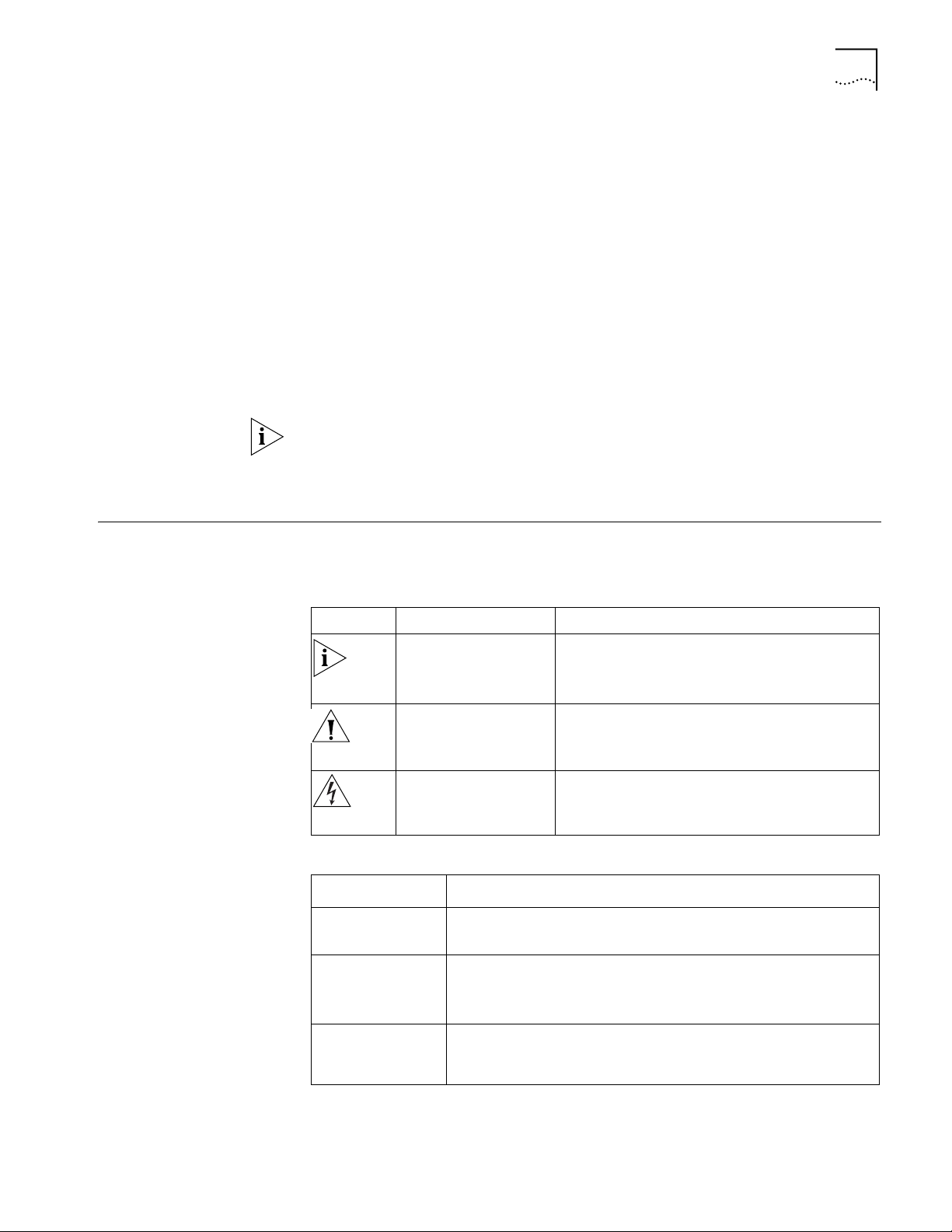
Conventions Ta bl e 1 and Tab l e 2 list conventions that are used throughout this guide.
Ta bl e 1 Notice Icons
Icon Notice Type Description
Information note Information that describes important features or
instructions.
Caution Information that alerts you to potential loss of data
or potential damage to an application, system, or
device.
Warning Information that alerts you to potential personal
injury.
Ta bl e 2 Text Conventions
Convention Description
Screen
displays
Keyboard key
names
This typeface represents information as it appears on the screen.
If you must press two or more keys simultaneously, the key names are
linked with a plus sign (+), for example:
Press Ctrl+Alt+Del
The words “enter”
and type”
When you see the word “enter” in this guide, you must type
something, and then press Return or Enter. Do not press Return or
Enter when an instruction simply says “type.”
Page 6

6 CHAPTER : ABOUT THIS GUIDE
Words in italics Italics are used to:
Emphasize a point.
Denote a new term at the place where it is defined in the text.
Identify menu names, menu commands, and software button names.
Examples:
From the Help menu, select Contents.
Click OK.
Words in bold Boldface type is used to highlight command names. For example,
“Use the display user-interface command to...”
Page 7

INTRODUCING THE ROUTER 3000
1
FAMILY
Routers in the 3Com® Router 3000 Family provides the following types of ports:
■ Ethernet port
■ Synchronous/asynchronous serial port
■ Auxiliary (AUX) port
■ ISDN BRI S/T and U port
■ CT1/PRI port
■ E1/CE1/PRI port
These features allow you to combine the various networking technologies, such as
PSTN/ISDN, FR (Frame Relay), X.25, leased line, and T1 line. These multiple ports
also allow Router 3000 series routers to interoperate with the products of other
manufacturers.
Router 3000 routers use three types of memory:
■ Synchronous Dynamic Random Access Memory (SDRAM) — Saves router
operation system software
■ Flash memory — Saves router program files, configuration files and so on
■ Boot ROM — Saves the boot and initialization programs of the router
Router 3012 Figure 1 illustrates the Router 3012.
Figure 1 Router 3012
Power LED
100M Ethernet LED
SERIAL0 LED
SERIAL1 LED
AUX LED
System LED
Page 8
8 CHAPTER 1: INTRODUCING THE ROUTER 3000 FAMILY
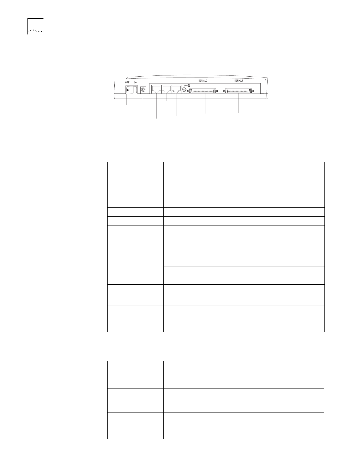
Figure 2 illustrates the back panel of the Router 3012.
Figure 2 Back Panel of the Router 3012
Power
switch
Power
input
socket
AUX
port
Console
port
Grounding
screw
100M
Ethernet
port
SERIAL0
SERIAL1
System Specifications Ta bl e 3 lists system specifications for the Router 3012.
Ta bl e 3 System Specifications for the Router 3012
Item Description
Fixed ports 1 10/100 Mbps Ethernet port
2 synchronous/asynchronous serial ports
1 AUX port
1 console port
Processor MPC860T 50M Hz
SDRAM 64 MB
Flash memory 8 MB
Maximum power 20 W
Power supply (external) Input voltage and frequency: 100 to 240V AC (the actual range can
be 80 to 264 V) 50/60 Hz
Input current: 0.5 A to 1 A
Output voltage: 12 V
Output current: 4 A
Dimensions (W X H X
D, highest arc points of
the plastic panel)
Weight 0.75 kg (1.65 lb)
Operating temperature 0 to 400 C (32 to 1040 F)
Relative humidity 5 to 85% (noncondensing)
251 X 42.5 X 187 mm (9.9X 1.7 X 7.4 in)
LEDs Ta bl e 4 lists and describes the LEDs on the front panel of the Router 3012.
Ta bl e 4 Router 3012 LEDs
LED Description
POWER Off —The power is off.
Green — The power is on.
100M ETH Off — The link is not connected.
Flashing green — Data is being transmitted through the Ethernet
port.
SERIAL0 Off — The link is not connected.
Green — The link is connected.
Flashing green — Data is being transmitted through serial port 0.
Page 9

Router 3012 9
Table 4 Router 3012 LEDs (continued)
LED Description
SERIAL1 Off — The link is not connected.
Green — The link is connected.
Flashing green — Data is being transmitted over serial port 1.
AUX Off — The link is not connected.
Green — The link is connected.
Flashing green — Data is being transmitted over the AUX port.
SYSTEM Flashing green — The system is operating normally.
Always green or off — The system is not operating normally.
Port Attributes The Router 3012 provides a console port, an AUX port, a 10/100M Ethernet port
and a synchronous/asynchronous serial port. The attributes of these ports are
described in the following sections.
Console Port
Ta bl e 5 lists attributes of the console port.
Ta bl e 5 Attributes of the Console Port
Attribute Description
Connector RJ-45
Port standard Asynchronous EIA/TIA-232
Baud rate 9.6 to 115.2 kbps (the default is 9.6 kbps)
Services Connects with character terminal
Connects with the serial ports of the local PCs and runs the terminal
emulation program on the PCs
Command line interface
AUX Port
Ta bl e 6 lists attributes of the AUX port.
Ta bl e 6 Attributes of the AUX Port
Attribute Description
Connector RJ-45
Port standard Asynchronous EIA/TIA-232
Baud rate 300 bps to 115.2 kbps
Services Modem dial-up
Backup
Protocols PPP (Point to Point Protocol)
SLIP (Serial Line Internet Protocol)
MP (Multilink PPP)
Page 10

10 CHAPTER 1: INTRODUCING THE ROUTER 3000 FAMILY
Ethernet Port
Ta bl e 7 lists attributes of the Ethernet port.
Ta bl e 7 Attributes of the Fast Ethernet Port
Attribute Description
Connector RJ-45
Frame format Ethernet_II
Operating mode 10/100 Mbps autosensing
Network protocol IP (Internet Protocol)
Synchronous/Asynchronous Serial Port
Ta bl e 8 lists attributes of the serial port.
Ta bl e 8 Attributes of the Serial Port
Ethernet_SNAP
IEEE 802.2
IEEE 802.3
Full duplex/half duplex
Novell IPX (Internet Packet Exchange)
Description
Attribute
Connector DB50
Port standard and
operating mode
Minimum baud
rate (bps)
Maximum baud
rate (bps)
Services DDN leased line
Protocols PPP
Synchronous Asynchronous
V.24
(EIA/TIA-23
2)
DTE, DCE DTE, DCE DTE DCE
1200 1200 1200 1200 300
64 k 2.048 M 2.048 M 2.048 M 115.2 K
Terminal access
Backup
MP
LAPB (Link Access Protocol-Balanced)
HDLC (High-level Data Link Control)
SDLC (Synchronous Data Link Control)
X.25
Frame Relay
V.35 EIA/TIA-449, X.21 and
V.24 (EIA/TIA-232)
EIA-530
Modem dial-up
Backup
PPP
SLIP
MP
Router 3013 and Router 3015
The Router 3013 and Router 3015 offer ISDN BRI support. The Router 3013 has an
ISDN BRI S/T port and the Router 3015 has an ISDN BRI U port.
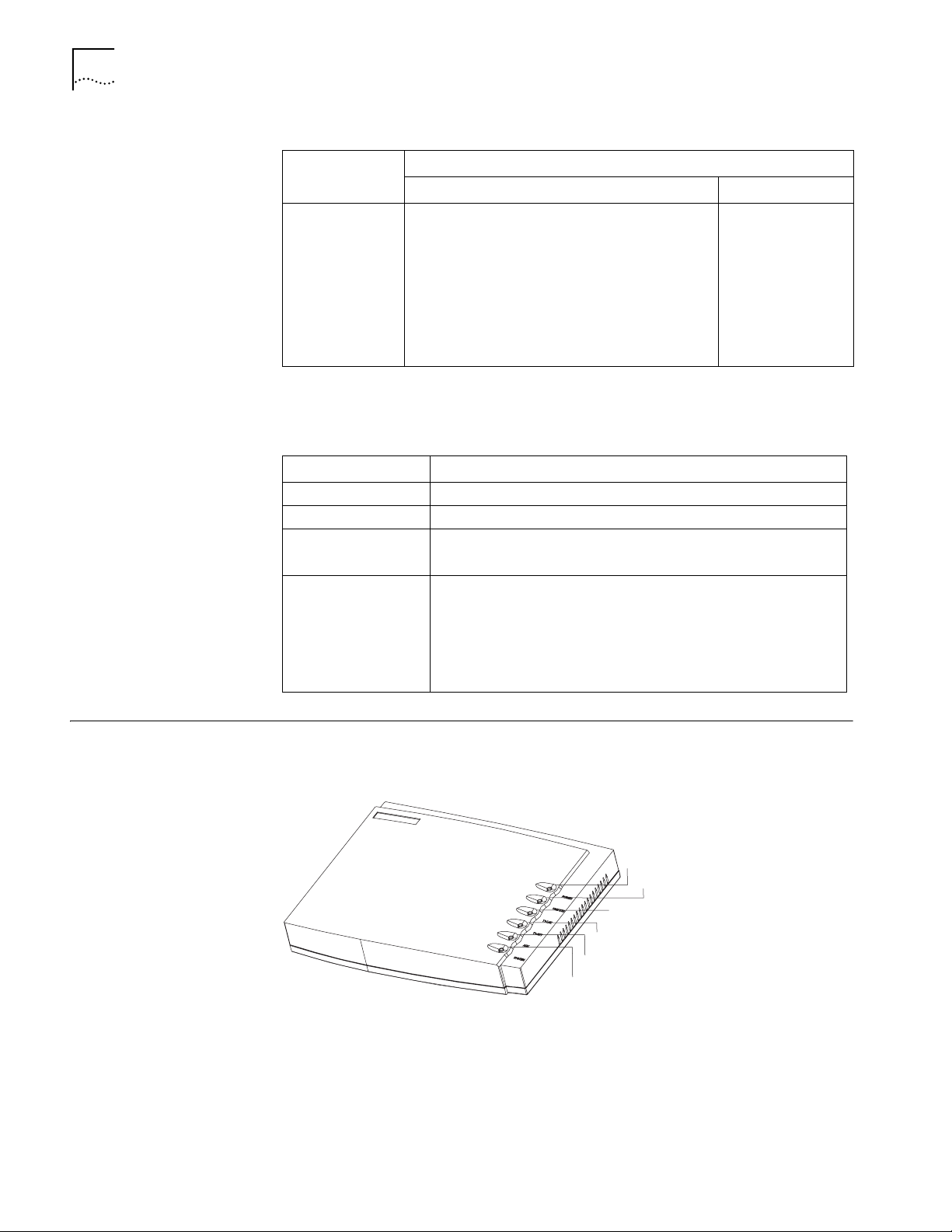
Figure 3 illustrates the Router 3013 and Router 3015 routers.
Page 11
Router 3013 and Router 3015 11
Figure 3 Router 3013 and Router 3015
Power LED
100M Ethernet LED
Serial LED
BRI LED
AUX LED
System LED
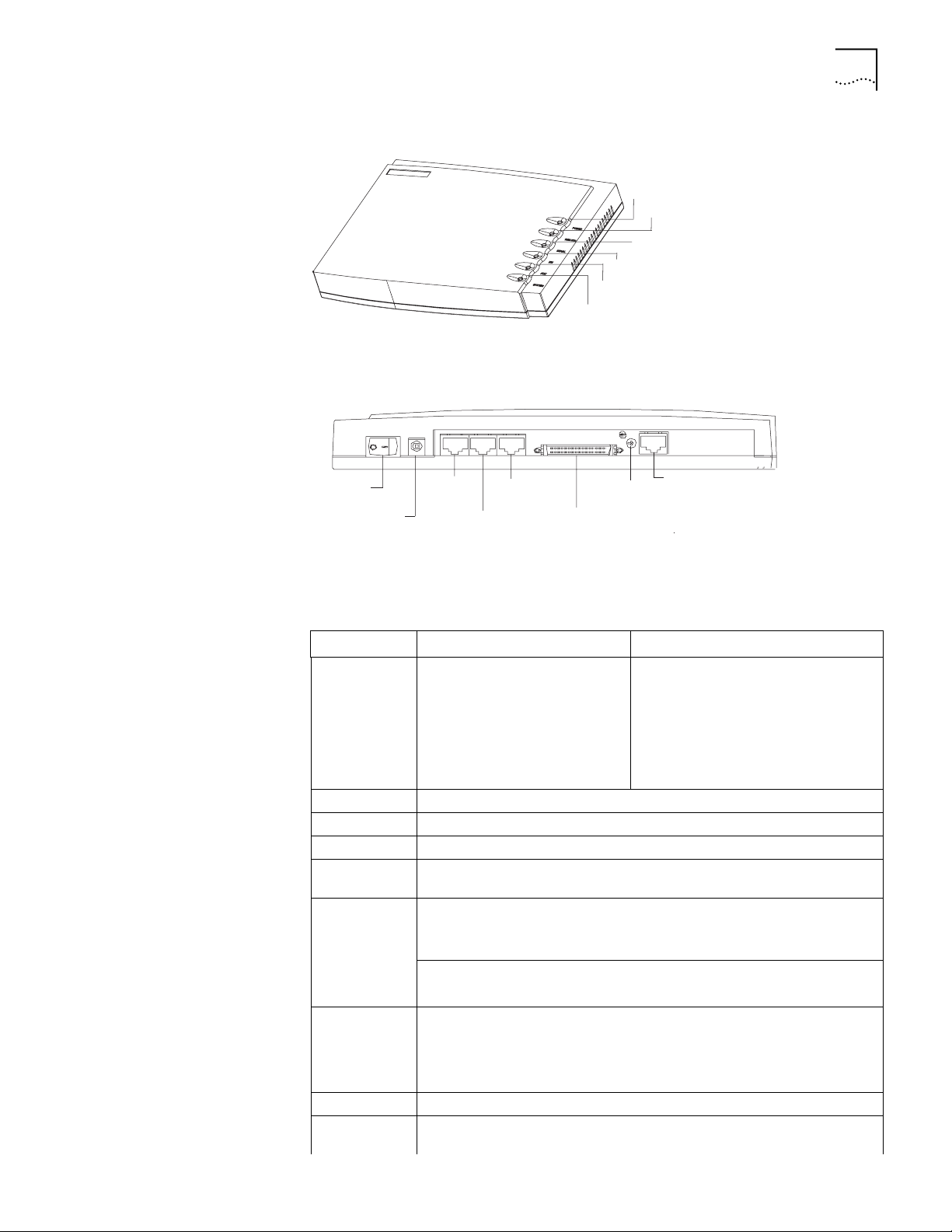
Figure 4 illustrates the back panel of the Router 3013 and 3015.
Figure 4 Back Panel of the Router 3013 and Router 3015
OFF ON
Power
switch
Power
input
socket
CON AUX 100M ETH SERIAL BRI
DC12V
CON
port
AUX
port
100M
Ethernet
port
SERIAL0
Grounding
screw
BRI port
System Specifications Tab le 9 lists system specifications for the Router 3013 and Router 3015.
Ta bl e 9 System Specifications for the Router 3013 and Router 3015
Item Router 3013 Description Router 3015 Description
Fixed ports 1 console port
1 10/100M Ethernet port
1 AUX port
1 synchronous/asynchronous
serial port
1 ISDN BRI S/T port
Processor MPC860T 50 MHz
SDRAM 64 MB
Flash memory 8 MB
Maximum
20 W
power
Power supply
(external)
Input voltage and frequency: 100 to 240V AC (the actual range can be 80 to
264 V) 50/60 Hz
Input current: 0.5 A to 1A
Output voltage: 12 V
Output current: 4 A
Dimensions (W
251 X 42.5 X 187mm (9.9 X 1.7 X 7.4 in)
X H X D, the
highest arc
points of the
plastic panel)
Weight 0.75 kg (1.65 lb)
Operating
0 to 40 C (32 to 1040 F)
temperature
1 console port
1 10/100M Ethernet port
1 AUX port
1 synchronous/asynchronous serial port
1 ISDN BRI U port
Page 12

12 CHAPTER 1: INTRODUCING THE ROUTER 3000 FAMILY
Table 9 System Specifications for the Router 3013 and Router 3015 (continued)
Item Router 3013 Description Router 3015 Description
Operating
humidity
5 to 85% (noncondensing)
LEDs Ta bl e 10 lists and describes the LEDs on the front panel of the Router 3013 and
Router 3015.
Ta bl e 10 Router 3013 and Router 3015 LEDs
LED Description
POWER Off — The power is not on.
100M ETH Off — The link is not connected.
SERIAL Off — The link is not connected.
BRI Off — No data is being transmitted over the ISDN BRI port and two B
AUX Off — The link is not connected.
SYSTEM Flashing green — The system is operating normally.
Green — The power is on.
Flashing green — Data is being transmitted over the Ethernet port.
Green — The link is connected.
Flashing green — Data is being transmitted over the serial port.
channels are free.
Flashing green — Data is being transmitted over the ISDN BRI port.
Green means — The link is connected.
Flashing green — Data is being transmitted over the AUX port.
Always green or off — The system is not operating normally.
Port Attributes The Router 3013 provides a console port, an AUX port, a 10/100M Ethernet port,
a synchronous/asynchronous serial port, and an ISDN S/T port.
The Router 3015 provides a console port, an AUX port, a 10/100M Ethernet port,
a synchronous/asynchronous serial port, and an ISDN U port.
Console Port
Ta bl e 11 lists attributes of the console port.
Ta bl e 11 Attributes of the Console Port
Attribute Description
Connector RJ-45
Port standard Asynchronous EIA/TIA-232
Baud rate 9.6 to 115.2 kbps (9.6 kbps is the default)
Services Connects with terminal
Connects with serial ports of the local PCs and runs the terminal
emulation program on the PCs
Command line interface
Page 13

AUX Port
Ta bl e 12 lists attributes of the AUX port.
Ta bl e 12 Attributes of the AUX Port
Attribute Description
Connector RJ-45
Port standard Asynchronous EIA/TIA-232
Baud rate 300 bps to 115.2 kbps
Services Modem dial-up
Backup
Protocols PPP (Point to Point Protocol)
SLIP (Serial Line Internet Protocol)
MP (Multilink PPP)
Ethernet Port
Ta bl e 13 lists attributes of the Ethernet port.
Ta bl e 13 Attributes of the Fast Ethernet Port
Attribute Description
Connector RJ-45
Frame format Ethernet_II
Ethernet_SNAP
IEEE 802.2
IEEE 802.3
Operating mode 10/100 Mbps autosensing
Full duplex/half duplex
Network protocol IP (Internet Protocol)
Novell IPX (Internet Packet Exchange)
Router 3013 and Router 3015 13
Synchronous/Asynchronous Serial Port
Ta bl e 14 lists attributes of the serial port.
Ta bl e 14 Attributes of the Serial Port
Description
Attribute
Connector DB50
Port standard and
operating mode
Minimum baud
rate (bps)
Maximum baud
rate (bps)
Services DDN leased line
Synchronous Asynchronous
V.24
(EIA/TIA-23
2)
DTE, DCE DTE, DCE DTE DCE
1200 1200 1200 1200 300
64 K 2.048 M 2.048 M 2.048 M 115.2 K
Terminal access
Backup
V.35 EIA/TIA-449, X.21 and
EIA-530
V.24 (EIA/TIA-232)
Modem dial-up
Backup
Page 14
14 CHAPTER 1: INTRODUCING THE ROUTER 3000 FAMILY
Table 14 Attributes of the Serial Port (continued)
Attribute
Protocols PPP
ISDN S/T and ISDN U Ports
Ta bl e 15 lists attributes of the ISDN S/T and ISDN U ports.
Ta bl e 15 Attributes of ISDN S/T and U Ports
Attribute Description
Connector RJ-45
Protocol standards Complies with ITU-T I.430, Q.921 and Q.931 recommendations
Operating mode ISDN dial-up
Services ISDN
Description
Synchronous Asynchronous
PPP
MP
LAPB (Link Access Protocol-Balanced)
HDLC (High-level Data Link Control)
SDLC (Synchronous Data Link Control)
X.25
Frame Relay
ISDN leased line
ISDN additional services
Multi-subscriber number
Subaddress
Backup
SLIP
MP
Router 3016 and Router 3018
Figure 5 illustrates the Router 3016.
Figure 5 Router 3016
Power LED
Ethernet LED
T1-LNK LED
T1-ACT LED
AUX LED
System LED
Figure 6 illustrates the back panel of the Router 3016.
Page 15
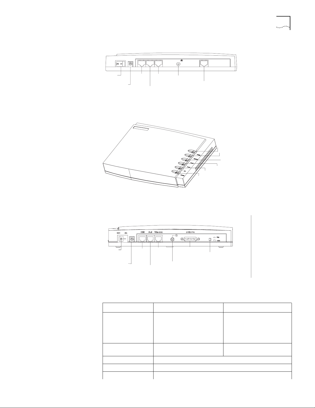
Figure 6 Back Panel of the Router 3016
Router 3016 and Router 3018 15
Power
switch
OFF ON
Power
input
socket
CON AUX100METH
AUX
port
100M
Ethernet
port
CON
port
Grounding
screw
CT1/PRI
CT1/PRI
port
Figure 7 illustrates the Router 3018.
Figure 7 Router 3018
Power LED
Ethernet LED
E1 Link LED
E1 ACT LED
AUX LED
System LED
Figure 8 illustrates the back panel of the Router 3018.
Figure 8 Back Panel of the Router 3018
Power
switch
Power
input
socket
CON
port
100M
Ethernet
port
AUX
port
Grounding
screw
E1/CE1/PRI
port
Port impedance
toggling button
System Specifications Tab le 16 lists system specifications for the Router 3016 and Router 3018.
Ta bl e 16 System Specifications for the Router 3016 and Router 3018
Item Router 3016 Description Router 3018 Description
Fixed ports 1 console port
1 10/100 Mbps Ethernet port
1 AUX port
1 CT1/PRI port
Button 1 E1/CE1/PRI port impedance
Processor MPC860T 50 MHz
SDRAM 64 MB
Flash memory 8 MB
1 console port
1 10/100 Mbps Ethernet port
1 AUX port
1 E1/CE1/PRI port
toggling button
Page 16

16 CHAPTER 1: INTRODUCING THE ROUTER 3000 FAMILY
Table 16 System Specifications for the Router 3016 and Router 3018 (continued)
Item Router 3016 Description Router 3018 Description
Maximum power 20 W
Power supply (external) Input voltage and frequency: 100 to 240V AC (the actual range can
Dimensions (W X H X D,
the highest arc points
of the plastic panel)
Weight 0.75 kg (1.65 lb)
Operating temperature 0 to 400 C (32 to 1040 F)
Operating humidity 5 to 85% (noncondensing)
LEDs Ta bl e 17 lists and describes the LEDs on the Router 3016 and Router 3018.
Ta bl e 17 Router 3016 LEDs
be 80 to 264 V) 50/60 Hz
Input current: 0.5A to 1A
Output voltage: 12 V
Output current: 4 A
251 X 42.5 X 187 mm (9.9 X 1.7 X 7.4 in)
LED Description
POWER Off — The power is not on.
Green — The power is on.
100M ETH Off — The link is not connected.
Flashing green — Data is being being transmitted over the Ethernet
port.
T1-LNK/E1-LNK Off — The link is not set up.
Green means — The link has been set up.
T1-ACT/E1-ACT Off — No data is being transmitted through the port.
Green — Data is being transmitted through the port.
AUX Off — No data is being transmitted through the AUX port.
Green — The link is connected.
Flashing green — Data is being transmitted through the AUX port.
SYSTEM Flashing green — The system is operating normally.
On or off — The system is not operating normally.
Port Attributes The Router 3016 provides a console port, an AUX port, a 10/100 Mbps Ethernet
port, and a CT1/PRI port.
The Router 3018 provides a console port, an AUX port, a 10/100 Mbps Ethernet
port, and a E1/CE1/PRI port.
Console Port
Ta bl e 18 lists attributes of the console port.
Ta bl e 18 Attributes of the Console Port
Attribute Description
Connector RJ-45
Port standard Asynchronous EIA/TIA-232
Page 17

Router 3016 and Router 3018 17
Table 18 Attributes of the Console Port (continued)
Attribute Description
Baud rate 9.6 to 115.2 kbps (the default is 9.6 kbps)
Services Connects with character terminal
Connects with serial ports of the local PCs and runs the terminal
emulation program on the PCs
Command line interface
AUX Port
Ta bl e 19 lists attributes of the AUX port.
Ta bl e 19 Attributes of the AUX Port
Attribute Description
Connector RJ-45
Port standard Asynchronous EIA/TIA-232
Baud rate 300 bps to 115.2 kbps
Services Modem dial-up
Backup
Protocols PPP (Point to Point Protocol)
SLIP (Serial Line Internet Protocol)
MP (Multilink PPP)
Ethernet Port
Ta bl e 20 lists attributes of the Ethernet port.
Ta bl e 20 Attributes of the Ethernet Port
Attribute Description
Connector RJ-45
Frame format Ethernet_II
Ethernet_SNAP
IEEE 802.2
IEEE 802.3
Operating mode 10/100 Mbps autosensing
Full duplex/half duplex
Network protocol IP (Internet Protocol)
Novell IPX (Internet Packet Exchange)
CT1/PRI and E1/CE1/PRI Ports
Ta bl e 21 lists attributes of the CT1/PRI and and E1/CE1/PRI ports.
Ta bl e 21 Attributes of the CT1/PRI Port
Attribute CT1/PRI Description E1/CE1/PRI Description
Connector RJ-45 DB15
Port standard G.703/T1 102 and G.704
Port rate 1.544 Mbps 2.048 Mbps
Page 18

18 CHAPTER 1: INTRODUCING THE ROUTER 3000 FAMILY
Table 21 Attributes of the CT1/PRI Port (continued)
Attribute CT1/PRI Description E1/CE1/PRI Description
Operating mode Channelized T1
Services Backup
Protocols PPP
E1
Fractional T1
ISDN PRI
Terminal access
ISDN
MP
HDLC
LAPB
X.25 (ITU-T X series Recommendations)
Frame Relay
Q.921
Q.931
Q.SIG
Channelized E1
Fractional E1
ISDN PRI
Page 19

2
INSTALLING THE ROUTER
There are two ways you can install your router:
■ On a vertical surface
■ On a workbench
The following sections describe how to prepare and install your router:
■ Preparing to Install the Router
■ Mounting the Router on a Vertical Surface
■ Installing the Router on a Workbench
■ Connecting the Protection Ground Wire
■ Connecting the Power Cable
■ Connecting the Router to the Console Terminal
■ Connecting the Router to the Ethernet
Preparing to Install the Router
Safety Warnings Before installing your router, consider the following safety guidelines:
■ Connecting the Router to the WAN
■ Verifying the Installation
This section provides guidelines for preparing your site and router for installation.
■ Switch off the power supply before connecting the cables.
■ Keep the router far away from any heat source.
■ To ensure normal heat dissipation, do not stack routers.
■ Do not keep a router in a damp place, and prevent liquid from getting into the
router.
■ Ensure that the neutral point of the power is grounded properly, to avoid
personal injury.
■ Ensure that the power is off before plugging or unplugging the interface cards,
modules and cables of the router.
■ Before removing the chassis, disconnect all the power cords and external
cables.
■ To avoid damage to the router, connect all the cables correctly. Never connect
telephone cables (including the ISDN lines) to the console or AUX port.
Page 20

20 CHAPTER 2: INSTALLING THE ROUTER
■ During the installation, wear an ESD (Electro-Static Discharge) preventive wrist
3Com recommends that you use an uninterrupted power supply (UPS) with your
router.
strap and ESD-preventive gloves. See
“Static Electricity” on page 20 for
additional information on ESD prevention.
General Site
Requirements
The environment of the installation site influences the performance and lifetime of
the router. The installation site for your router should meet the following
requirements for temperature and humidity, dust, gases, static electricity, and
electromagnetic discharge.
Temperature and Humidity
To ensure normal operation and to prolong the operational lifetime of the router,
the temperature and humidity of the equipment room must be within controlled
limits. The requirements for the temperature and humidity of the router
installation site are listed in
Ta bl e 22 Temperature and Humidity Requirements
Temperature Relative humidity
00 to 400C (320 to 1040F) 5% to 85%
Ta bl e 22.
Dust
Dust is harmful to the safe operation of the router. The specifications for the dust
content and diameter of the granule within the equipment room are listed in
Ta bl e 23.
Ta bl e 23 Specification for Dust Content
Maximum diameter (µ m) 0.5 1 3 5
Maximum density (the number
of granules per cubic meter)
1.4 x 10
7
7 x 10
5
2.4 x 10
5
1.3 x 10
5
Gases
The equipment room of the router must meet strict requirements for the content
of salt, acid and sulfide. The specific limitation values of these harmful gases are
2
2
3
2
Ta bl e 24.
0.2 1.5
0.04 0.15
0.05 0.15
0.01 0.3
given in
Ta bl e 24 Harmful Gas Limitation Values in Equipment Room
Gas Average (mg/m3) Maximum (mg/m3)
SO
H2S 0.0 0.03
NO
NH
Cl
Static Electricity
To prevent damage caused by the static electricity, insure that:
■ The equipment is grounded
Page 21

Preparing to Install the Router 21
■ The equipment room is dust-proof
■ Adequate temperature and humidity conditions prevail
■ The operator wears the ESD-preventive wrist strap, ESD-preventive gloves and
ESD-preventive clothes while handling the circuit board.
■ The dismantled circuit board is placed upward on the ESD preventive
workbench, or put into an ESD preventive bag.
■ You avoid direct contact with the elements of the circuit board.
Electromagnetic Discharge
To prevent damage by electromagnetic discharge, do the following:
■ Take effective measures against electrical net interference for the power supply
system.
■ Separate the working ground of the router from the grounding device of the
power equipment, or thunder proof grounding.
■ Keep the router away from wireless launchers, radar launchers and other high
frequency and high current equipment.
Lightning Damage
To minimize the risk of lightning damage do the following:
■ Install a lightning arrester on the input end of a telephone cable, ISDN line or
T1/E1 line.
■ Ensure that the PGND wire of the chassis is well grounded
■ Ensure that the neutral point of the socket of AC power supply is well
grounded
■ Install a lightning arrester at the input end of the power supply
Workbench
Requirements
Whether you install the router in a rack or place it directly on the workbench, it is
necessary to ensure that:
■ Airflow is not restricted around the router.
■ The cabinet and workbench are strong enough to support the weight of the
router and other installation accessories.
■ The cabinet and workbench are well grounded.
Installation Checklist After you verify that the installation conditions comply with these requirements,
open the packing case of the router and check the contents against the your order
contract. Contact your Service representative if you find any discrepancies.
To install your router, you will need:
■ To ol s
■ Phillips screwdriver
■ Flat-head screwdriver
■ ESD-preventive wrist strap and ESD-preventive gloves
■ Flat-blade screws (used in wall mounting)
■ Cables
Page 22

22 CHAPTER 2: INSTALLING THE ROUTER
■ Equipment
■ Ethernet cable
■ Console cable
■ AUX cable
■ Power supply, power cord, and chassis ground wire
A router
Ethernet 10/100BASE-T Hub or LAN switch
Channel service unit/data service unit (CSU/DSU) or other data communications
equipment (DCE) equipment (such as a modem)
Configuration terminal, such as a PC
Mounting the Router on a Vertical Surface
The Router 3000 can be mounted onto a vertical surface using two pan-head
screws aligned to the brackets on the base of the router. To mount the router on a
vertical surface, do the following:
1 Mark the bracket positions on the wall.
2 Screw two pan-head screws into the marked positions on the wall or other vertical
surface, so that the screws match the position of the two brackets on the base of
the router. Each screw should project 0.6 cm (.25 in) from the wall or the surface.
3 Make sure that the front panel LEDs are easily visible to the operator.
4 Hang the router on the screws by the two brackets.
5 Secure the external power supply of the router to prevent the power cords from
detaching.
See Figure 9 and Figure 10 for illustrations of this procedure.
Figure 9 The Bottom of the Router
4.72in
120mm
Page 23

Installing the Router on a Workbench 23
Figure 10 Mounting the Router on a Vertical Surface
Pan-head screw
Installing the Router on a Workbench
Connecting the Protection Ground Wire
You can install any Router 3000 on a workbench.
To install the router on a workbench, take the following precautions:
■ Ensure that the workbench is smooth and stable.
■ Leave a heat-dissipation clearance of 10 m (4 in) around the router.
■ Do not put heavy objects on the router.
The protection ground (PGND) point of the chassis is located on the left side of the
rear panel, near the power switch and is labeled with a grounding label, as shown
Figure 11. The grounding resistance should not be greater than 5 ohm.
in
Figure 11 Connecting the PGND
Copper
grounding bar
PGND
Connecting the Power Cable
Connect the PGND wire before connecting other cables. Shorten the ground wire
as much as possible to avoid the router and the peer device being damaged during
lightning.
To connect the router to the power outlet and confirm that the PGND wire is
properly grounded, do the following:
1 Connect the output end of the power supply to the power socket on the rear
panel of the router.
2 Connect the input end of the power supply to the AC power outlet.
3 Turn on the power switch on the router.
4 Confirm that the router has power by checking whether the POWER LED is on.
Page 24

24 CHAPTER 2: INSTALLING THE ROUTER
If you repeat this procedure several times and the POWER LED remains off, see
“The Power LED is Off.” on page 49.
Figure 12 illustrates the power supply.
Figure 12 Router 3000 Power Supply
Connecting the Router to the Console Ter mi nal
Connecting the Router to the Ethernet
The Router 3000 provides a console port, through which you can configure the
router.
The console cable is an 8-core shielded cable. The end that is used to connect to
the console port of the router has an RJ-45 connector. The other end of the
console cable has both a DB-9 (female) adapter and a DB-25 (female) adapter. Use
the appropriate connector for the port on the console terminal.
See Appendix A for the illustration and pinout details of the console cable.
To configure the router through the console terminal:
1 Turn off power to the router.
2 Select a console terminal — This can be either a standard ASCII terminal with an
RS-232 serial port, or a PC.
3 Connect the cable — Turn the power switch off, and then connect the serial
interface of the console cable to the console port of the router.
After connection, power on the router. The startup information of the router is
displayed on the console terminal.
The Router 3000 routers provide a fixed 10/100BASE-TX fast Ethernet port that
uses category-5 twisted pair cable.
See Chapter A for the illustration and pinout details of the Ethernet cables.
Note the following before you connect:
■ The fixed Ethernet cables are supplied with the router.
■ Use shielded cables to ensure electromagnetic compatibility.
■ Identify the mark on the module port so you can plug the cable in correctly.
■ When connecting the Ethernet cable to a LAN Switch, plug the cable into the
10/100BASE-T port marked with MDIX.
Page 25

Connecting the Router to the WAN 25
To connect the Ethernet cable:
1 Turn off power to the router.
2 Select the Ethernet cable.
When connecting the router with a PC or a router, use the crossover network
cable.
When connecting the router to a hub or a LAN switch, use the straight-through
network cable.
3 Connect one end of the Ethernet cable to the appropriate Ethernet module on the
router.
4 Connect the other end of the Ethernet cable to the Ethernet port of the network
device.
5 Verify the connection by checking that the 100M ETH LED on the top of the router
is on.
Connecting the Router to the WAN
Connecting the AUX
Port to the Modem
The Router 3000 series routers provide the following WAN ports:
■ AUX port (all models)
■ Mutiprotocol synchronous/asynchronous serial port (Router 3012, Router
3013, Router 3015)
■ ISDN S/T port (Router 3013)
■ ISDN U port (Router 3015)
■ CT1/PRI port (Router 3016)
■ E1/CE1/PRI port (Router 3018)
See Chapter A for illustrations and pinout details of all WAN port cables.
The auxiliary (AUX) port is an EIA/TIA-232-compliant synchronous/asynchronous
serial port that is used for remote configuration or dial-up backup. To connect the
router to a remote device, a local modem must be connected to a remote modem
through PSTN. For the connection method, see
Chapter 3. For the AUX port
specifications of each router, see Chapter 1.
If the console port fails, the AUX port can also serve as a console port.
To connect the AUX cable:
1 Turn off power to the router.
Connecting the Serial
Port to a CSU/DSU
2 Plug the RJ-45 connector of the AUX cable into the AUX port of the router.
3 Connect the DB-25 or DB-9 adapter of the AUX cable to the serial port of the
analog modem.
For pinout details of the AUX cable, see Appendix A.
The serial port is usually used to connect the router to DSU/CSU. For the serial port
specifications of each router, see
Chapter 1.
CAUTION: Plugging and unplugging the connectors of the serial port online can
damage the router or the remote device.
Page 26

26 CHAPTER 2: INSTALLING THE ROUTER
Nine types of serial port cables are available. However, these cables are optional
and you must select the proper one based on your requirements when you
purchase the router. All these types of cables have a DB-50 adapter at the router
end.
For pinout details of the serial port cables, see Appendix A.
At the network end, the connector is different for each type of cable, as described
in the following list:
■ V.24 (EIA/TIA-232) DTE cable — DB-25 (male) adapter
■ V.24 (EIA/TIA-232) DCE cable — DB-25 (female) adapter
■ V.35 DTE cable — 34-pin (male) adapter
■ V.35 DCE cable — 34-pin (female) adapter
■ X.21 DTE cable — DB15 (male) adapter
■ X.21 DCE cable — DB15 (female) adapter
■ EIA/TIA-449 DTE cable — DB37 (male) adapter
■ EIA/TIA-449 DCE cable — DB37 (female) adapter
Connecting to the
CT1/PRI Port
■ EIA-530 DTE cable — DB25 (male) adapter
Use the following procedure to connect the serial cable to the SERIAL0 port and
the DSU/CSU device:
1 Turn off power to the router.
2 Choose the appropriate serial cable.
3 Plug the DB-50 adapter of the cable into the SERIAL0 port of the router.
4 Connect the other end of the cable to the CSU/DSU device. (If the WAN uses a
dial-up line, connect the cable to the serial port of the analog modem. See
“Connecting the AUX Port to the Modem” on page 25.
The Router 3016 hass a CT1/PRI port that provides CT1 (channelized T1) access
and implements the ISDN function. See
Ta bl e 21 on page 17.
The CT1/PRI cable is a 100-ohm shielded straight-through cable with RJ-45
connectors at both ends.
For pinout details of the T1 cable, see Appendix A.
To connect the T1 cable:
1 Turn off power to the router.
CAUTION: Identify the mark on the CT1/PRI port. Plugging the connector in
incorrectly can cause damage to the router.
2 Insert the connector at one end of the T1 cable into the CT1/PRI port of the router.
3 Insert the connector at the other end of the T1 cable into the corresponding port
in a WAN device.
4 Power on the router and verify that the T1-LNK LED on the front panel of the
router chassis is lit. If it is off, check the connection cable.
Page 27

Verifying the Installation 27
Connecting to the ISDN
BRI Port
The Router 3013 router has an ISDN S/T port and the Router 3015 router has an
ISDN U port. These routers perform data transfer in 2B+D mode and support both
ISDN dial-up and leased line. See
Ta bl e 15 on page 14 for the ISDN port attributes.
The ISDN S/T cable is a 4-core twisted pair cable. Both ends of the cable have
RJ-45 connectors. The 3-pin and 6-pin connectors are at the sending end, and the
4-pin and 5-pin connectors are at the receiving end.
The ISDN U cable is a 2-core twisted pair cable. One end has an RJ11 connector
and the other end has an output terminal (OT) connector.
For illustrations and pinout details of the ISDN BRI cables, see Appendix A.
To connect the ISDN BRI port:
1 Turn off power to the router.
CAUTION: Identify the router model and the ISDN BRI mark on the port when
making the connection. Plugging the connector in incorrectly can cause damage
to the router
2 Confirm the type of ISDN line provided by the telecommunications service
provider.
3 Connect the cable.
For the Router 3013:
Verifying the Installation
a If the line is ISDN U, use an NT1 adapter. Insert one end of the S/T cable into
the S/T port of the NT1, and the other end into the ISDN BRI port of the router.
b If the line is ISDN S/T, insert the cable directly into the ISDN BRI port of the
router
For the Router 3015, the line must be ISDN U.
Connect the RJ-45 connector to the ISDN BRI port of the router, and connect the
output terminal (OT) end to the ISDN line through a telephone adapter.
Verify whether the router has been correctly installed by checking the following
items:
■ There is airflow around the router
■ Power is connected correctly
■ The ground wire of the router is correctly connected
■ The router is connected to other devices, such as the console terminal
Page 28

28 CHAPTER 2: INSTALLING THE ROUTER
Page 29

BOOTING AND CONFIGURING THE
3
Connecting the Router to a Local Console Te rm i na l
ROUTER
During the initial configuration of the router, you can use only the console or AUX
port. This chapter describes how to connect the router to a local or remote
console terminal and how to set parameters at the console terminal.
To set up the local configuration environment, connect the RJ-45 connector of the
console cable to the console port on the router, and the DB-25 connector or DB-9
connector to the serial port of a PC, as shown in
Figure 13 Local Configuration Through the Console Port
RS232 Serial interface
Router 3012
PC
Figure 13.
Setting the Parameters of the Console Terminal
Console port
Console cable
To set terminal parameters:
1 Start the PC and select Start > Programs > Accessories > Communications >
HyperTerminal.
The HyperTerminal window displays the Connection Description dialog box, as
shown in
Figure 14.
Page 30

30 CHAPTER 3: BOOTING AND CONFIGURING THE ROUTER
Figure 14 Connection Description Dialog Box
2 Enter the name of the new connection in the Name field and click OK. The
Connect To dialog box, shown in
Figure 15 displays.
Figure 15 Connect To Dialog Box
3 Select the serial port for the connection from the Connect using dropdown menu
and click OK. The Connection Properties dialog box, shown in
Figure 16 displays.
Page 31

Setting the Parameters of the Console Terminal 31
Figure 16 Connection Properties Dialog Box
4 Set the following parameters:
Bits per second — 9600
Data bits — 8
Parity — None
Stop bits — 1
Flow control — None.
5 Click OK. The HyperTerminal dialog box displays, as shown in Figure 17.
Page 32

32 CHAPTER 3: BOOTING AND CONFIGURING THE ROUTER
Figure 17 HyperTerminal Window
6 Select Properties. The Properties dialog box for your connection displays.
7 Click the Settings tab, shown in Figure 18.
Figure 18 Settings Tab
8 In the Emulation dropdown menu, select VT100 or Auto detect. Click OK.
Page 33

Powering on the Router 33
Powering on the Router
Checking and Operating
after Power-on
Before you power on the router, verify that:
■ The connection between the power cord and ground wire is secure
■ The voltage of the power supply complies with the requirement of the router
■ The console cable is correctly connected to either the PC or the terminal, and
that the parameters are correct, as described in
“Setting the Parameters of the
Console Terminal” on page 29.
WARNING: Before switching on the power, locate the power-off switch in the
workroom so that, in case of an electrical accident, power can be turned off
quickly.
Turn on the power switch of the router.
After the router is powered on, verify that:
■ The LEDs on the front panel are normal.
For the status of the LEDs during normal operation after power-on, see the LED
tables in
■ The console terminal display is normal
Chapter 1.
For the local configuration, the startup interface on the console terminal
displays after the router is powered on. See
“Startup Process” on page 33.
For the remote configuration, you must dial up, using HyperTerminal, after the
router is powered on, as shown in
Figure 19. After the dial-up, the startup
interface is displayed on the terminal. See “Startup Process” on page 33.
Figure 19 Connect Dialog Box
After the POST, press Enter. When the [3Com] prompt displays, you can configure
the router.
Startup Process After the router starts up, the Boot ROM program runs and the following
information displays on the terminal screen:
Booting
********************************************
Page 34

34 CHAPTER 3: BOOTING AND CONFIGURING THE ROUTER
* 3Com Router Boot Rom, V4.60
********************************************
Copyright(C) 2002-2005 by 3Com Corporation, Inc.
Compiled at 20:46:59 , Jul 25 2003.
Now testing memory...OK
64M bytes SDRAM
8192k bytes flash memory
Hardware Version is MTR 0.1
CPLD Version is CPLD 1.0
Bootrom Version is V1.00
Press Ctrl-B to Enter Boot Menu
The contents displayed on the terminal can vary with different versions of Boot
ROM.
If you press Ctrl+B immediately, the system displays the Boot Menu. If you do not
press Ctrl+B, the system initiates the program decompression process.
Configuration Fundamentals of the Router
After “3Com Router Boot Rom, V4.60” appears, “Booting” disappears.
When the system begins the decompression and initialization process, the screen
displays:
Now system is self-decompressing...
System now is starting...
Press ENTER to get started
Press Enter. The system displays the [3Com] prompt, which indicates that the
router has entered the system view and you can configure the router.
The configuration process includes the following steps:
1 Clarify your networking requirements. These requirements include:
■ The connectivity requirements of the remote sites
■ The types of LAN and WAN ports required for the network
■ The configuration of IP and IP subnet settings and any other protocols
■ The network reliability, management, and security policies
2 Based on your network requirements, draw a clear and integrated networking
diagram.
Page 35

Configuration Fundamentals of the Router 35
3 Configure the WAN port of the router:
■ Configure the physical operating parameters (the operating mode of the serial
port, baud rate, and synchronous clock) of the port according to the
transmission medium of the WAN. For the dial-up port, you need to configure
DDR parameters.
■ Configure the link layer protocol encapsulated on the port and the related
operating parameters according to the type of the WAN.
4 Configure the IP addresses or IPX network number for all the ports of the router
according to the division of the subnets.
5 Configure the routes. If you have to start up the dynamic routing protocol,
configure the related operating parameters of the protocol.
6 Create the security configuration for the router, as necessary.
7 Create the reliability configuration for the router, as necessary.
SNMP Management For help managing routers on your network, you can use 3Com Network
Supervisor software to discover, map, and display network links and IP devices.
To allow Network Supervisor to monitor your routers, you must first configure
SNMP V1 and SNMP Trap support with the following commands:
[3Com]snmp-agent sys-info version v1
[3Com]snmp-agent community read <read-community-string>
[3Com]snmp-agent community write <write-community-string>
[3Com]snmp-agent trap enable
[3Com]snmp-agent target-host trap address <addr> parameter
v1 securityname <security-name-string>
In this example, <addr> is the address of the PC on which you have installed Network
Supervisor.
To learn more about Network Supervisor, on the 3Com Corporation World Wide
Web site, enter this URL into your Internet browser:
http://www.3com.com/3ns
Command Line Interface The command line interface of the Router 3000 series routers provides commands
to configure and manage the router. The command line interface has the
following characteristics:
■ Performs the local configuration through the console port.
■ Performs local or remote configuration through the telnet command, which
can be used to log on directly and manage other routers.
■ Implements the configuration on the router through the terminals (the
asynchronous port, including those connected to the AUX port and AS port) in
the dumb terminal mode.
■ Configures the hierarchical user protection (guest, operator, administrator).
Only administrator users are authorized to configure and manage the routers.
■ Online help, available by typing ? at any time.
Page 36

36 CHAPTER 3: BOOTING AND CONFIGURING THE ROUTER
■ Provides network diagnostic tools, such as Tracert and Ping, to quickly diagnose
the availability of the network.
■ Provides detailed debugging information to diagnose network faults.
■ The command line interpreter adopts fuzzy search for the keywords of the
command. A conflict-free keyword if entered, will be interpreted accordingly.
For example, for a display command, you can enter dis.
To facilitate the management of the router in the system view, all the commands
are grouped. Each group corresponds to a view. Users can use these commands to
switch between different views. Many commands are limited to use in a single
view. Other commands (such as ping, display current-configuration, interface)
can be executed in all views.
Help for the
Configuration
Router 5000 routers provide online Help for the command line interface:
■ In any view, enter ? for all the commands in the view and a brief description of
each command.
■ Enter a command, followed by a space and ?, in the keyword position for a list
of all keywords and a brief description of each one.
■ Enter a command, followed by a space and ?, in the argument position for a
description of related arguments.
■ Enter a character string, followed by a space and ?, for a list of all commands
that begin with the character string.
■ Enter a command, followed by a character string and ?, for a list of all
keywords that begin with the string.
Page 37

4
MAINTAINING THE ROUTER
Software Maintenance
Accessing the Boot
Menu
The Router 3000 supports three types of software file:
■ BootROM program files
■ Application files
■ Configuration files
This chapter describes the configuration methods you can use to upgrade, upload
and download configuration files and application files, and manage the BootROM
password.
The Boot menu is used during software maintenance of the router. Create a
configuration environment (see
page 34) and boot the router. The terminal screen displays the following
information:
Booting
******************************************
* R3000 Boot Rom, V4.60
******************************************
Copyright(C) 2002-2005 by 3Com Corporation, Inc.
Compiled at 20:46:59 , Jul 25 2003.
Now testing memory...OK!
64M bytes SDRAM
8192k bytes flash memory
“Configuration Fundamentals of the Router” on
Press Ctrl-B to Enter Boot Menu
Press Ctrl + B within 5 seconds. The system prompts you for the BootROM
password:
Please input bootrom password :
If you do not press Ctrl + B within 5 seconds, the system begins decompression,
and you must restart the router.
Page 38

38 CHAPTER 4: MAINTAINING THE ROUTER
Enter the Boot ROM password, if there is one, and press Enter. The Boot menu
displays:
Boot Menu:
1: Download application program with XMODEM
2: Download application program with TFTP
3: Clear application password
4: Clear configuration
5: Start up and ignore console configuration
6: Download Boot ROM ALL with XMODEM
7: Restore Boot ROM from FLASH
8: Backup Boot ROM from FLASH
9: Exit and reboot
Enter your choice(1-9):
The Boot menu provides two methods for upgrading the applications. See
“Downloading Applications with the Xmodem Protocol” on page 38 and
“Downloading Applications with the TFTP Protocol” on page 40.
CAUTION: When you upgrade application programs, verify and match the version
of the Boot ROM software to the version of the main software.
Downloading
Applications with the
Xmodem Protocol
If you download software applications using the Xmodem protocol, you can use
the console port.
Use the following process to download applications with the Xmodem protocol:
1 Enter the Boot menu.
2 Press 1 to select the Download application program with Xmodem. The router
provides the following download speed options:
Downloading application program from serial ...
Please choose your download speed:
1: 9600 bps
2: 19200 bps
3: 38400 bps
4: 57600 bps
5: 115200 bps
6: Exit and reboot
Enter your choice(1-6):
3 Select the appropriate download speed. The router displays information based on
your selection, for example:
Download speed is 115200 bps. Change the terminal's speed to 115200
bps, and select Xmodem protocol. Press ENTER key when ready.
4 Change the baud rate at the console terminal to make it consistent with your
selection in Step 3.
To allow the new baud rate to take effect, you must disconnect the terminal and
reconnect it.
5 Press Enter to begin the download. The system displays the following prompt:
Downloading ... CCCCC
6 Select Tra ns mit /S e nd file in the terminal window.
Page 39

Software Maintenance 39
7 Select Browse in the Send File dialog box, shown in Figure 20, and select the
application you want to download.
Figure 20 Send File Dialog Box
8 In the Protocol dropdown menu, select Xmodem.
9 Click Send. The system displays the Xmodem file send dialog box, shown in
Figure 21.
Figure 21 Xmodem File Send Dialog Box
After the download is complete, the system begins the operation of writing to
Flash memory, after which, the following information will be displayed in the
terminal interface, indicating that the download is completed:
Download completed.
Writing to flash memory...
Please wait,it needs a long time (about 5 min).
#############################
Write Flash Success.
Please return to 9600 bps. Press ENTER key to reboot the system.
Page 40

40 CHAPTER 4: MAINTAINING THE ROUTER
10 Restore the baud rate of the console terminal to 9600bps and repeat the
disconnection and reconnection of the terminal.
Downloading BootROM
with the Xmodem
Protocol
Downloading
Applications with the
TFTP Protocol
To upgrade the Boot ROM by using Xmodem:
1 Power on the router start the POST, and press Ctrl+B within 5 seconds of the
prompt that tells you to do so.
2 Enter the Boot ROM password at the prompt:
Please input bootrom password:
The terminal displays the following menu:
Boot Menu:
1: Download BootRom program
2: Modify BootRom password
3: Reboot
Enter your choice(1-3):
3 Enter 1 and continue with Step 3 in “Downloading Applications with the Xmodem
Protocol” on page 38.
TFTP Server software is not provided with your router but you can download a free
copy from:
ftp://ftp.3com.com/pub/utilbin/win32/3ts01_04.exe
To download application upgrades with the TFTP protocol, you must create the
configuration shown in
Figure 22.
Figure 22 TFTP Upgrade Environment
PC (TFTP Server)
10.110.10.13
Ethernet interface
LAN
LAN
Console cable
Router 3012
10.110.10.10
Console port
(TFTP Client)
Creating the TFTP Upgrade Configuration:
1 Connect the ETHERNET port to a PC through a crossover network cable.
2 Connect the console port of the router to an external console terminal and
configure HyperTerminal. See
“Setting the Parameters of the Console Terminal ”
on page 29.
3 Install the TFTP Server on the PC.
4 Copy the new application files to a suitable path. The default is C:\R3000.
5 Configure the IP address for the Ethernet port on the PC, and assume that the
address is 10.110.10.13.
6 Start the TFTP Server on the PC. The TFTP dialog box displays.
Page 41

Software Maintenance 41
7 Depending on your TFTP server interface, click on the appropriate icon or button,
to set the path for the application on your system.
Configuring the Router
1 Enter the TFTP configuration status.
2 Boot the router and press N immediately when Booting displays on the screen. The
following information displays on the terminal interface:
(M)odify any of router configuration or (C)ontinue? [M]
3 Press Enter. The following information displays:
For each of the following questions, you can press <Return> to select
the value shown in braces, or you can Enter a new value.
NETWORK INTERFACE PARAMETERS:
Do you want a LAN interface? [N] y
This board's LAN IP address? [169.254.10.10]10.110.10.10
Subnet mask for LAN (0 for none)? [255.255.0.0]
TFTP SERVER PARAMETERS:
Configure the TFTP Server parameters, including IP address of the
Ethernet interface on the PC, file name of the application program,
CPU delay time and so on.
IP address of the TFTP server? [169.254.75.166]10.110.10.13
What is the name of the file to be loaded and started? [m8241ram.arj]
How long (in seconds) should CPU delay before starting up? [5]
4 Configure the network interface parameters for the router, including the interface
to be used, its IP address, and subnet mask.
As you configure these parameters, set the values so that:
■ The IP address of the TFTP server is the IP address of the PC connected to the
Ethernet port on the router.
■ The IP address and subnet mask are the same as the IP address and subnet
mask of the LAN0 port.
■ The IP addresses of the PC network interface and the LAN0 port of the
router reside on the same segment.
After you enter the last parameter, the following information displays and you can
verify that the parameters are set correctly.
---------------------------------------------------------------NETWORK INTERFACE PARAMETERS:
IP address on LAN is 10.110.10.10
LAN interface's subnet mask is 0xffff0000
HARDWARE PARAMETERS:
Processor type is MPC8241
Internal Clock Rate 200 Mhz
External Clock Rate 100 Mhz
Serial channels will use a baud rate of 9600
TFTP SERVER PARAMETERS:
IP address of the TFTP host is 10.110.10.13
The file to download and start is m8241ram.arj
After board is reset, start-up code will wait 5 seconds
--------------------------------------------------------------(M)odify any of this or (C)ontinue? [M]C
5 Enter C to confirm this configuration or M to modify any of the parameter
settings.
Page 42

42 CHAPTER 4: MAINTAINING THE ROUTER
Upgrading the Application
To upgrade the application:
1 Boot the system normally.
2 Press Ctrl+B within 5 seconds of the prompt that tells you to do so.
3 Enter the BootROM password, if necessary.
4 Enter 2 at the Boot menu, to select Download the Application Program Through
TFTP. The following information displays:
Please start TFTP server then press ENTER key to get started
5 If the PC running TFTP Server is ready, press Enter to begin loading the program.
Starting the TFTP download...
..................................................................
TFTP download completed...
read len=[03713478]
Writing program code to FLASH...
Please waiting,it needs a long time (about 5 min)
##############################
Write Flash Success.
Press ENTER key to reboot the system.
Uploading and
Downloading
Applications and
Configuration Files
Using FTP
6 After the loading, press Enter to reboot the router.
Uploading files involves transferring them from a PC running the FTP client to a
router running the FTP server, through the router’s Ethernet port. This is called a
put operation.
Downloading files involves transferring them from the FTP server on the router,
through its Ethernet port, to the PC running the FTP client. This is called a get
operation. All FTP clients, including local and remote users, who are connected to
a router can upload and download if they pass user authentication.
Creating a Local FTP Upload/Download Configuration
To transfer files using FTP, you must create the appropriate configuration, as shown
Figure 23 and Figure 24, and described in the following procedures.
in
Figure 23 Creating a Local FTP Upload/Download Configuration
10.110.10.13
LAN
(FTP Client)
PC
Ethernet port
100METHCON AUX
DC12V
Router 3012 (FTP Server)
LAN
10.110.10.10
100METHCON AUX
DC12V
Router 3012 (FTP Server)
To create a local FTP upload/download configuration:
1 Connect the PC to any of the Ethernet ports on the router.
2 Configure the IP address for the Ethernet port on the router. The default IP address
is 10.110.10.10.
3 Configure the IP address of the Ethernet port on the PC. The default IP address is
10.110.10.13.
Page 43

Software Maintenance 43
The IP addresses of the PC network port and of the router’s Ethernet port must be
on the same segment.
4 Copy the application program files to a path, the default is C:\version.
Creating a Remote FTP Upload/Download Configuration
Figure 24 illustrates a remote FTP upload/download configuration
Figure 24 Creating a Remote FTP Upload/Download Configuration
Router 3012
100METHCON AUX
DC12V
WAN
100METHCON AUX
DC12V
Router 3012 (FTP Server)
PC (FTP Client)
To create a remote FTP upload/download configuration:
1 Connect the PC to any port on the router through a WAN. This procedure does
not require that the IP address of the PC and that of the router be on the same
segment.
2 Copy the application program files or configuration files to a suitable path. The
default is C:\version.
To start the FTP server on the router and to set the user name and password, you
should work with the maintenance personnel at the router site. All FTP client
programs can use the username and password to log on to the FTP server.
To start the FTP server and set the user name and password:
1 Set the authentication mode:
[3Com] aaa-enable
[3Com] aaa authentication-scheme login default local
[3Com] aaa accounting-scheme optional
2 Add the user name and password:
[3Com] local-user user password simple 123 service-type ftp
where user is the user name and 123 is the password.
3 Start the FTP server:
[3Com] ftp-server enable
Uploading or Downloading an Application or Configuration File
To upload or download an application program file or configuration file:
1 In DOS mode, enter the path where the application or configuration files are
located.
2 Execute the FTP command and set up the FTP connection with the router. For
example:
C:\version\ftp 10.110.10.10
If the connection is set up, the following information displays:
Connected to 10.110.10.10
Page 44

44 CHAPTER 4: MAINTAINING THE ROUTER
220 FTP server ready on R3000 at
User(10.110.10.10:(none)):
3 Use the username and password that have already been set on the router to log
on to the FTP server.
User(10.110.10.10:(none)): user
331 Password required for ftp
Password:
230 User ftp logged in
ftp>
The appearance of the ftp> prompt indicates that you can begin the upload or
download operation.
During the upload and download operation, the default name of the router’s
application program is SYSTEM. Configurations file are named CONFIG by default.
4 To upload the application or configuration files, enter the appropriate path and file
name at the following prompts:
ftp>put
local file
remote file
Creating a New Router
Password
After the uploading is completed, the ftp> DOS prompt displays again.
5 Enter dir to display the name and size of the file on the router. If the upload is
successful, the sizes of the file on the router and on the PC will be the same.
6 To download the application or configuration files, enter the appropriate path and
file name at the following prompts:
ftp>get
local file
remote file
After the upload or download is complete, exit the FTP client
program:
ftp>quit
If the router’s Boot ROM password or user password is lost, use the following
procedure:
1 Boot the router.
2 Press Ctrl+B within 5 seconds of the prompt that tells you to do so.
3 Enter 3 at the Boot Menu:
Boot Menu:
1: Download application program with Xmodem
2: Download application program with TFTP
3: Clear application password
4: Clear configuration
5: Start up and ignore Console configuration
6: Exit and reboot
Enter your choice(1-6):3
4 When the Boot menu is shown again, enter 6 to exit the Boot menu and run the
router’s main software.
5 Press Enter in the system view to enter the user password directly.
[3Com] local-user user password simple service-type
exec-administrator 123
Page 45

Software Maintenance 45
In this example, user indicates the user name, 123 indicates the new user
password.
[R3000] quit
[R3000] save
6 Execute the save command after modifying the user password to save the
change.
[R3000] quit
[R3000] save
If the Boot ROM password for the router is lost, contact your Service
representative.
Page 46

46 CHAPTER 4: MAINTAINING THE ROUTER
Maintaining Router Hardware
Opening the Cover of
Router Chassis
In preparation for the maintenance of your router hardware, have the following
tools:
■ Phillips screwdriver
■ ESD-preventive wrist strap and ESD-preventive glove
■ Static shielding bag
■ Chip extractor
CAUTION: Observe the following precautions when maintaining your router
hardware:
■ On the Router 3000, there is a seal on one of the screws on the chassis.
Contact your Service representative before you open the chassis.
■ Always maintain the router under the guidance of technical support personnel.
■ Confirm that all power supplies have been disconnected from the router when
performing hardware maintenance.
■ Wear an ESD-preventive wrist strap and ESD-preventive gloves during hardware
maintenance and ensure that the strap makes skin contact.
■ Use only the SDRAM provided by 3Com Corporation.
Use the following procedure to open the router chassis cover:
1 Turn off the power to router and remove the power cord.
2 Remove all port cables on the back panel of the router. Do not remove the PGND
cable.
3 Place the router upside down on a work surface. Remove the screws on the
bottom of the chassis with the Phillips screwdriver and set them aside.
4 Turn the router right side up, with the rear panel toward you.
5 Remove the captive screws on the rear panel with the Phillips screwdriver and set
them aside.
6 Raise the chassis cover until it is free of the bottom of the router, and put it to one
side.
Figure 25 Removing the Screws from the Bottom of the Router Chassis
Page 47

Maintaining Router Hardware 47
Replacing the Boot ROM When a Boot ROM is damaged or when data becomes corrupted because of a
software failure and cannot be corrected, the Boot ROM should be replaced.
Router 3000 Boot ROMs are located at the same position on the mainboard, as
shown in
Figure 26 Boot ROM Location
Figure 26.
Boot ROM location
Closing the Router
Chassis Cover
CAUTION: Use a chip extractor to replace the Boot ROM.
To replace the Boot ROM:
1 Insert the top end of the chip extractor into the Boot ROM socket, turn inward
slightly, withdraw the extractor upward and lift the Boot ROM out.
2 Put the Boot ROM into the static shielding bag.
3 Insert the end of the chip extractor into the socket of the new Boot ROM.
4 Position the Boot ROM so that the beveled edge of the socket matches the
beveled edge on the Boot ROM and plug it into the Boot ROM socket.
CAUTION: Be careful not to damage or bend the pins at the bottom of the Boot
ROM. If the pins are bent, straighten them with needle-nose pliers.
To prevent cables from being pressed or cut off when you close the cover of the
router chassis, roll up all the cables and put them into the chassis before closing
the cover.
Page 48

48 CHAPTER 4: MAINTAINING THE ROUTER
Page 49

TROUBLESHOOTING
5
The Power LED is Off. If the power LED is off, verify that:
■ The power switch of the router is turned on.
■ The power supply switch is turned on.
■ The power cord of the router is connected properly.
■ The power supply suits the requirement of the router.
CAUTION: Do not plug in or unplug the power cord when the power is on. After
having checked the conditions in the previous list, if the power LED is still off,
contact your Service representative.
Nothing is Displayed on the Terminal after Power-On
After the system runs the power-on self-test (POST), if the system operates
normally, the start-up information is displayed on the console terminal. If the
configuration system has a fault, the terminal may display nothing.
If the terminal does not display any information after the POST, verify that:
■ The power system is operating normally.
■ The console cable is connected correctly.
If the power system is normal and the console cable is connected properly, there
may be something wrong with the console cable or the HyperTerminal
parameters. Check the cable or the parameters.
HyperTerminal parameters should have the following values:
■ Baud — 9600
■ Data bits — 8
■ Stop bit — 1
■ Parity — None
■ Flow control — None
■ Terminal emulation — VT100
If the parameter settings do not match these values, reconfigure them.
If the previous checks do not solve the problem, contact your Service
representative and follow the representative’s instructions.
Page 50

50 CHAPTER 5: TROUBLESHOOTING
Illegible Characters Display on the Terminal after Power-On
If the system operates normally after the system runs the POST, the start-up
information is displayed on the console terminal. If the configuration system has a
fault, the terminal may display only illegible characters.
If the console terminal displays illegible characters after the POST, verify that the
HyperTerminal parameters are set properly, as follows:
■ Baud: 9600
■ Data bits: 8
■ Stop bit: 1
■ Parity: None
■ Flow control: None
■ Terminal emulation: VT100
If the parameter settings do not match these values, reconfigure them.
Page 51

OPTIONAL CABLE SPECIFICATIONS
A
The tables in this appendix describe the pinouts for the cables that you can use
with Router 3000 series routers. P
are not connected.
Console Cable Figure 27 illustrates the console cable.
Figure 27 Console Cable Assembly
ins that are not described in the following tables
Enlarged A side
Ta bl e 25 describes the console cable pinouts.
Ta bl e 25 Console Cable Pinouts
RJ-45 Signal Direction DB-25 DB-9 Signal
1 —> 5 8 CTS
2 —> 6 6 DSR
3 —> 3 2 RXD
4 <— 8 1 DCD
5 - 7 5 GND
DB25 Female
8P8C Plug
DB9 Female
Enlarged B side
Enlarged C side
6 <— 2 3 TXD
7 <— 20 4 DTR
8 <— 4 7 RTS
AUX Cable The AUX cable is an 8-core shielded cable. One end of the cable has an RJ-45
connector and connects to the AUX port of the router. The other end has both a
DB-25 (male) adapter and a DB-9 (male) adapter. Use the appropriate connector
for the port on the modem.
Page 52

52 CHAPTER A: OPTIONAL CABLE SPECIFICATIONS
e
Figure 28 illustrates the AUX cable.
Figure 28 AUX Cable Assembly
Enlarged A side
DB25 Male
Label
8P8C Plug
DB9Male
Ta bl e 26 describes the AUX cable pinouts.
Ta bl e 26 AUX Cable Pinouts
RJ-45 Signal Direction DB-25 DB-9 Signal
1 —> 4 7 RTS
2 —> 20 4 DTR
3 —> 2 3 TXD
4 <— 8 1 DCD
5 - 7 5 GND
Enlarged B side
Enlarged C sid
6 <— 3 2 RXD
7 <— 6 6 DSR
8 <— 5 8 CTS
Ethernet Cable The Ethernet cable uses an RJ-45 connector and category 5 twisted pair cable.
The Router 3000 series routers provide a fixed 10/100BASE-TX fast Ethernet port
that uses category-5 twisted pair cable, as shown in
Figure 29 Ethernet Cable Assembly
The Ethernet cables are classified as straight-through network cable and crossover
network cable. They have the following features:
■ Straight-through network cable — The sequences of the wires crimped at the
RJ-45 connectors of the two ends are the same. The cable is used in the
connection between a terminal device, such as a PC or a router, and the Hub or
Figure 29
Page 53

Serial Port Cable 53
LAN Switch. Straight-through network cables are delivered along with the
router.
■ Crossover network cable — The sequences of the wires crimped at the RJ-45
connectors of the two ends are different. The cable is used in the connection
between the terminal device, such as a PC or a router, and another terminal
device. You can create this cable yourself, if necessary.
Ta bl e 27 describes straight-through network cable pinouts.
Ta bl e 27 Straight-through Network Cable Pinouts
RJ-45 Signal
1 TX+ White (Orange) —> 1
2 TX- Orange —> 2
3 RX+ White (Green) <— 3
4 - Blue - 4
5 - White (Blue) - 5
6 RX- Green <— 6
7 - White (Brown) - 7
8 - Brown - 8
Category 5
twisted pair
Signal Direction RJ-45
Ta bl e 28 describes crossover network cable pinouts.
Ta bl e 28 Crossover Network Cable Pinouts
Category 5
RJ-45 Signal
1 TX+ White (Orange) —> 3
2 TX- Orange —> 6
3 RX+ White (Green) <— 1
Twisted Pair
Signal Direction RJ-45
4 - Blue - 4
5 - White (Blue) - 5
6 RX- Green <— 2
7 - White (Brown) - 7
8 - Brown - 8
You can use Ta bl e 28 as a reference while distinguishing or preparing the two
kinds of Ethernet cables. While preparing the Ethernet cables, follow the
chromatogram given in this table to arrange the wires. Otherwise, communication
quality will be affected even though the equipment at two ends is connected.
Serial Port Cable The synchronous/asynchronous serial port cable is connected to a DB-50
receptacle. You must select the appropriate cable for the protocol.
Page 54

54 CHAPTER A: OPTIONAL CABLE SPECIFICATIONS
Synchronous and
Asynchronous mode
V.35 and V.24 (EIA/TIA-232) standards support synchronous operating mode,
while only V.24 (EIA/TIA-232) standard supports the asynchronous operating
mode. The maximum transmission distance and baud rate of the signal vary with
the operating mode. See
Ta bl e 29 Transmission Rate and Transmission Distance of V.24 (EIA/TIA-232)/V.35 Cable
V.24 (EIA/TIA-232) V.35
Baud Rate (bps)
2400 60 2400 1250
4800 60 4800 625
9600 30 9600 312
19200 30 19200 156
38400 20 38400 78
64000 20 56000 60
115200 10 64000 50
- - 2048000 30
Ta bl e 29 for details.
Maximum
Transmission
Distance (m)
Baud Rate (bps)
Maximum
Transmission
Distance (m)
CAUTION: The baud rate should not exceed 64 Kbps when the V.24 cable
operates in synchronous mode.
V.24 (EIA/TIA-232) DTE
Cable Pinouts
DTE and DCE mode
The synchronous serial port can operate in both DTE mode and DCE mode. For
two devices connected directly, one device should operate in DTE mode, and the
other device should operate in DCE mode. The DCE mode device provides a
synchronous clock and specifies the transmission rate, the DTE mode device
accepts the synchronous clock and communicates at the specified transmission
rate. Usually, the router serves as the DTE device. To determine whether the device
is a DTE or a DCE, refer to the user manual for the device.
Ta bl e 30 helps identify
DTE and DCE devices.
Ta bl e 30 Typical DTE and DCE
Type of
Equipment
DTE male PC or router
DCE female Modem, multiplexer or CSU/DSU
Type of Interface Typical Equipment
In general, the asynchronous serial interface is connected to a modem or a
terminal adapter (TA) to act as the dial-up interface. In this case, it is unnecessary
to determine whether the device is DTE or DCE, you must only select the
appropriate baud rate.
Figure 30 illustrates the V.24 DTE cable
Page 55

Figure 30 V.24 DTE Cable Assembly
Serial Port Cable 55
nlarged A side
DB50 Male
Label
DB25 Male
Ta bl e 31 describes V.24 (EIA/TIA-232) DTE cable pinouts.
Ta bl e 31 V.24 (EIA/TIA-232) DTE Cable Pinout
DB-50 Signal Signal Direction DB-25 Signal
5 TxD/RxD —> 2 TxD
27 RxD/TxD <— 3 RxD
2 RTS/CTS —> 4 RTS
31 CTS/RTS <— 5 CTS
6 DSR/DTR <— 6 DSR
30 DCD/LL <— 8 DCD
3 TxC/NIL <— 15 TxC
28 RxC/TxCE <— 17 RxC
1 LL/DCD —> 18 LTST
Enlarged B side
V.24 EIA/TIA-232 DCE
Cable Pinouts
26 DTR/DSR —> 20 DTR
4 TxCE/TxC —> 24 TxCE
50 GND - 1 Shield_GND
7 GND - 7 Circuit_GND
Figure 31 illustrates the V.24 DCE cable.
Figure 31 V.24 DCE Cable Assembly
DB25 Female
Enlarged B side
Enlarged A side
DB50 Male
Label
Ta bl e 32 describes V.24 (EIA/TIA-232) DCE cable pinouts.
Ta bl e 32 V.24 (EIA/TIA-232) DCE Cable Pinouts
DB-50 Signal Signal Direction DB-25 Signal
5 TxD/RxD —> 3 RxD
Page 56

56 CHAPTER A: OPTIONAL CABLE SPECIFICATIONS
Table 32 V.24 (EIA/TIA-232) DCE Cable Pinouts (continued)
DB-50 Signal Signal Direction DB-25 Signal
27 RxD/TxD <— 2 TxD
2 RTS/CTS —> 5 CTS
31 CTS/RTS <— 4 RTS
26 DTR/DSR —> 6 DSR
1 LL/DCD —> 8 DCD
4 TxCE/TxC —> 15 TxC
29 NIL/RxC —> 17 RxC
30 DCD/LL <— 18 LTST
6 DSR/DTR <— 20 DTR
28 RxC/TxCE <— 24 TxCE
50 GND - 1 Shield_GND
7 GND - 7 Circuit_GND
Page 57

V.35 DTE Cable Pinouts Figure 32 illustrates the V.35 DTE cable.
Figure 32 V.35 DTE Cable Assembly
Enlarged A side Enlarged B side
DB50 Male
Label
Ta bl e 33 describes V.35 DTE cable pinouts.
Ta bl e 33 V.35 DTE Cable Pinouts
DB-50 Signal Signal Direction 34PIN Signal
2 RTS/CTS —> C RTS
31 CTS/RTS <— D CTS
6 DSR/DTR <— E DSR
30 DCD/LL <— F RLSD
26 DTR/DSR —> H DTR
1 LL/DCD —> K LT
15 TxD/RxD+ —> P SD+
39 TxD/RxD- —> S SD-
20 RxD/TxD+ <— R RD+
44 RxD/TxD- <— T RD-
16 TxCE/TxC+ —> U SCTE+
40 TxCE/TxC- —> W SCTE-
19 RxC/TxCE+ <— V SCR+
43 RxC/TxCE- <— X SCR-
18 TxC/RxC+ <— Y SCT+
42 TxC/RxC- <— AA SCT-
50 GND - A Shield_GND
7 GND - B Circuit_GND
24 RxD-REST GND - -
49 RxC-REST GND - -
25 TxC-REST GND - -
Serial Port Cable 57
V.35 Male
V.35 DCE Cable Pinouts Figure 33 illustrates the V.35 DCE cable.
Page 58

58 CHAPTER A: OPTIONAL CABLE SPECIFICATIONS
Figure 33 V.35 DCE Cable Assembly
V.35 Female
Enlarged A side
DB50 Male
Label
Ta bl e 34 describes V.35 DCE cable pinouts.
Ta bl e 34 V.35 DCE cable Pinouts
Signal
DB-50 Signal
31 CTS/RTS <— C RTS
2 RTS/CTS —> D CTS
26 DTR/DSR —> E DSR
1 LL/DCD —> F RLSD
6 DSR/DTR <— H DTR
30 DCD/LL <— K LT
Direction
34PIN Signal
Enlarged B side
20 RxD/TxD+ <— P SD+
44 RxD/TxD- <— S SD-
15 TxD/RxD+ —> R RD+
39 TxD/RxD- —> T RD-
19 RxC/TxCE+ <— U SCTE+
43 RxC/TxCE- <— W SCTE-
17 NIL/RxC+ —> V SCR+
41 NIL/RxC- —> X SCR-
16 TxCE/TxC+ —> Y SCT+
40 TxCE/TxC- —> AA SCT-
50 GND - A Shield_GND
7 GND - B Circuit_GND
24 RxD-REST GND - -
49 RxC-REST GND - -
25 TxC-REST GND - -
X.21 DTE Cable Pinouts Figure 34 illustrates the X.21 DTE cable.
Page 59

Serial Port Cable 59
Figure 34 X.21 DTE Cable Assembly
Ta bl e 35 describes X.21 DTE cable pinouts.
Ta bl e 35 X.21 DTE Cable Pinouts
DB50 Signal Signal Direction Signal DB15
7 GND <--> Circuit GND 8
23 DTE/DCE - Circuit GND 8
50 GND <--> Shield GND 1
10 RTS/CTS+ -> Control+ 3
34 RTS/CTS- -> Control- 10
38 CTS/RTS+ <- Indication+ 5
14 CTS/RTS- <- Indication- 12
20 RXD/TXD+ <- Receiver+ 4
44 RXD/TXD- <- Receiver- 11
15 TXD/RXD+ -> Transmit+ 2
39 TXD/RXD- -> Transmit- 9
19 RXC/TXCE+ <- Timing+ 6
43 RXC/TXCE- <- Timing- 13
- Shielding sheath <--> Shielding sheath -
X.21 DCE Cable Pinouts Figure 35 illustrates the X.21 DCE cable.
Figure 35 X.21 DCE Cable Assembly
Ta bl e 36 describes X.21 DCE cable pinouts.
Ta bl e 36 X.21 DCE Cable Pinouts
DB50 Signal Signal Direction Signal DB15
7 GND <--> Circuit GND 8
50 GND <--> Shield GND 1
10 RTS/CTS+ -> Indication+ 5
34 RTS/CTS- -> Indication- 12
38 CTS/RTS+ <- Control+ 3
Page 60

60 CHAPTER A: OPTIONAL CABLE SPECIFICATIONS
Table 36 X.21 DCE Cable Pinouts (continued)
DB50 Signal Signal Direction Signal DB15
14 CTS/RTS- <- Control- 10
20 RXD/TXD+ <- Transmit+ 2
44 RXD/TXD- <- Transmit- 9
15 TXD/RXD+ -> Receiver+ 4
39 TXD/RXD- -> Receiver- 11
16 RXC/TXCE+ -> Timing+ 6
40 RXC/TXCE- -> Timing- 13
- Shielding sheath <--> Shielding sheath -
EIA/TIA-449 DTE Cable
Pinouts
Figure 36 illustrates the EIA/TIA-449 DTE cable.
Figure 36 EIA/TIA-449 DTE Cable Assembly
Ta bl e 37 describes EIA/TIA-449 DTE cable pinouts.
Ta bl e 37 EIA/TIA-449 DTE Cable Pinouts
DB50 Signal Signal Direction Signal DB37
7 GND <--> Circuit GND 19
23 DTE/DCE - Circuit GND 19
50 GND <--> Sield GND 1
8 DTR/DSR+ -> TR+ 12
32 DTR/DSR- -> TR- 30
13 DSR/DTR+ <- DM+ 11
37 DSR/DTR- <- DM- 29
10 RTS/CTS+ -> RS+ 7
34 RTS/CTS- -> RS- 25
38 CTS/RTS+ <- CS+ 9
14 CTS/RTS- <- CS- 27
36 DCD/DCD+ <- RR+ 13
12 DCD/DCD- <- RR- 31
1 LL/LL -> LL 10
20 RXD/TXD+ <- RD+ 6
44 RXD/TXD- <- RD- 24
15 TXD/RXD+ -> SD+ 4
39 TXD/RXD- -> SD- 22
16 TXCE/RXC+ -> TT+ 17
Page 61

Serial Port Cable 61
Table 37 EIA/TIA-449 DTE Cable Pinouts (continued)
DB50 Signal Signal Direction Signal DB37
40 TXCE/RXC- -> TT- 35
19 RXC/TXCE+ <- RT+ 8
43 RXC/TXCE- <- RT- 26
18 TXC/NIL+ <- ST+ 5
42 TXC/NIL- <- ST- 23
- Shielding sheath <--> Shielding sheath -
EIA/TIA-449 DCE Cable
Pinouts
Figure 37 illustrates the EIA/TIA-449 DCE cable.
Figure 37 EIA/TIA-449 DCE Cable Assembly
Ta bl e 38 describes EIA/TIA-449 DCE cable pinouts.
Ta bl e 38 EIA/TIA-449 DCE Cable Pinouts
DB50 Signal Signal Direction Signal DB37
7 GND <--> Circuit GND 19
50 GND <--> Shield GND 1
8 DTR/DSR+ -> DM+ 11
32 DTR/DSR- -> DM- 29
13 DSR/DTR+ <- TR+ 12
37 DSR/DTR- <- TR- 30
10 RTS/CTS+ -> CS+ 9
34 RTS/CTS- -> CS- 27
38 CTS/RTS+ <- RS+ 7
14 CTS/RTS- <- RS- 25
36 DCD/DCD+ <- RR+ 13
12 DCD/DCD- <- RR- 31
20 RXD/TXD+ <- SD+ 4
44 RXD/TXD- <- SD- 22
15 TXD/RXD+ -> RD+ 6
39 TXD/RXD- -> RD- 24
16 TXCE/RXC+ <- RT+ 8
40 TXCE/RXC- <- RT- 26
19 RXC/TXCE+ <- TT+ 17
43 RXC/TXCE- <- TT- 35
17 NIL/TXC+ <- ST+ 5
Page 62

62 CHAPTER A: OPTIONAL CABLE SPECIFICATIONS
Table 38 EIA/TIA-449 DCE Cable Pinouts (continued)
DB50 Signal Signal Direction Signal DB37
41 NIL/TXC- <- ST- 23
- Shielding sheath <--> Shielding sheath -
EIA-530 DTE Cable
Pinouts
Figure 38 illustrates the EIA-530 DTE cable.
Figure 38 EIA-530 DTE Cable Assembly
Ta bl e 39 describes EIA-530 DTE cable pinouts.
Ta bl e 39 EIA-530 DTE Cable Pinouts
DB50 Signal Signal Direction Signal DB25
7 GND <--> Circuit GND 7
23 DCE/DTE - Circuit GND 7
50 GND <--> Shield GND 1
8 DTR/DSR+ -> DTR+ 20
32 DTR/DSR- -> DTR- 23
13 DSR/DTR+ <- DSR+ 6
37 DSR/DTR- <- DSR- 22
10 RTS/CTS+ -> RTS+ 4
34 RTS/CTS- -> RTS- 19
38 CTS/RTS+ <- CTS+ 5
14 CTS/RTS- <- CTS- 13
36 DCD/DCD+ <- DCD+ 8
12 DCD/DCD- <- DCD- 10
1 LL/LL -> LL 18
20 RXD/TXD+ <- RXD+ 3
44 RXD/TXD- <- RXD- 16
15 TXD/RXD+ -> TXD+ 2
39 TXD/RXD- -> TXD- 14
16 TXCE/RXC+ -> TXCE+ 24
40 TXCE/RXC- -> TXCE- 11
19 RXC/TXCE+ <- RXC+ 17
43 RXC/TXCE- <- RXC- 9
18 TXC/NIL+ <- ST+ 15
42 TXC/NIL- <- ST- 12
- Shielding sheath <--> Shielding sheath -
Page 63

T1 Cable Figure 39 illustrates the T1 cable.
Figure 39 T1 Cable
T1 Cable 63
RJ-45
RJ-45
Ta bl e 40 describes T1 cable pinouts.
Ta bl e 40 T1 Cable Pinouts
Straight-through
Shielded
RJ-45
1 White (Orange) Rx Ring 1
2 Orange Rx Tip 2
3 White (Green) - - 3
4 Blue Tx Ring 4
5 White (Blue) Tx Tip 5
6 Green - - 6
7 White (Brown) - - 7
8 Brown - - 8
Network Cable
Signal Description RJ-45
ISDN BRI Cables Figure 40 illustrates the the ISDN S/T Port cable.
Figure 40 ISDN S/T Port Cable
Ta bl e 41 describes ISDN S/T port cable pinouts.
Ta bl e 41 ISDN S/TPort Cable Pinouts
RJ-45 Signal RJ-45
1 - 1
2 - 2
3 Tx+ 3
4 Rx+ 4
5 Rx- 5
6 Tx- 6
7 - 7
8 - 8
Figure 41 illustrates the ISDN U port cable.
Page 64

64 CHAPTER A: OPTIONAL CABLE SPECIFICATIONS
Figure 41 ISDN U Port Cable
Ta bl e 42 describes ISDN U port cable pinouts.
Ta bl e 42 ISDN U Port Cable Pinouts
RJ-45 Signal
1 -
2 -
3 -
4 Ring
5 Tip
6 -
7 -
8 -
Page 65

OBTAINING SUPPORT FOR YOUR
B
Register Your Product to Gain Service Benefits
Purchase Value-Added Services
ROUTER
To take advantage of warranty and other service benefits, you must first register
your product at
on accounts that you create or have authorization to access. First time users must
apply for a user name and password that provides access to a number of eSupport
features including Product Registration, Repair Services, and Service Request.
To enhance response times or extend warranty benefits, contact 3Com or your
authorized 3Com reseller. Value-added services can include 24x7 telephone
technical support, software upgrades, onsite assistance or advance hardware
replacement. Experienced engineers are available to manage your installation with
minimal disruption to your network. Expert assessment and implementation
services are offered to fill resource gaps and ensure the success of your networking
projects. More information on 3Com Extended Warranty and Professional Services
is available at
Contact your authorized 3Com reseller or 3Com for additional product and
support information.
http://eSupport.3com.com/. 3Com eSupport services are based
http://www.3com.com/
Troubleshoot Online You will find support tools posted on the 3Com web site at
http://www.3com.com/
■ 3Com Knowledgebase helps you troubleshoot 3Com products. This
http://knowledgebase.3com.com
Access Software Downloads
query-based interactive tool is located at
and contains thousands of technical solutions written by 3Com support
engineers.
■ Connection Assistant helps you install, configure and troubleshoot 3Com
desktop and server NICs, wireless cards and Bluetooth devices. This diagnostic
software is located at:
http://www.3com.com/prodforms/software/connection_assistant/ca_th
ankyou.html
Software Updates are the bug fix / maintenance releases for the version of
software initially purchased with the product. In order to access these Software
Updates you must first register your product on the 3Com web site at
http://eSupport.3com.com/.
First time users will need to apply for a user name and password. A link to
software downloads can be found at
Product Support heading at
http://www.3com.com/
http://eSupport.3com.com/, or under the
Page 66

66 APPENDIX B: OBTAINING SUPPORT FOR YOUR ROUTER
Software Upgrades are the software releases that follow the software version
included with your original product. In order to access upgrades and related
documentation you must first purchase a service contract from 3Com or your
reseller.
Contact Us 3Com offers telephone, e-mail and internet access to technical support and repair
services. To access these services for your region, use the appropriate telephone
number, URL or e-mail address from the list below. You will find a current directory
of support telephone numbers posted on the 3Com web site at
http://csoweb4.3com.com/contactus/
Telephone Technical Support and Repair
To obtain telephone support as part of your warranty and other service benefits,
you must first register your product at
http://eSupport.3com.com/
When you contact 3Com for assistance, please have the following information
ready:
■ Product model name, part number, and serial number
■ A list of system hardware and software, including revision level
■ Diagnostic error messages
■ Details about recent configuration changes, if applicable
To send a product directly to 3Com for repair, you must first obtain a return
authorization number (RMA). Products sent to 3Com, without authorization
numbers clearly marked on the outside of the package, will be returned to the
sender unopened, at the sender’s expense. If your product is registered and under
warranty, you can obtain an RMA number online at
http://eSupport.3com.com/. First time users will need to apply for a user name
and password.
Telephone numbers are correct at the time of publication. Find a current directory
of support telephone numbers posted on the 3Com web site at
http://csoweb4.3com.com/contactus/
Country Telephone Number Country Telephone Number
Asia, Pacific Rim Telephone Technical Support and Repair
Australia
Hong Kong
India
Indonesia
Japan
Malaysia
New Zealand
Pakistan
You can also obtain support in this region using the following e-mail: apr_technical_support@3com.com
Or request a repair authorization number (RMA) by fax using this number: + 65 543 6348
Europe, Middle East, and Africa Telephone Technical Support and Repair
1 800 678 515
800 933 486
+61 2 9424 5179 or
000800 650 1111
001 803 61009
00531 616 439 or
03 5977 7991
1800 801 777
0800 446 398
+61 2 9937 5083
Philippines
P.R. of China
Singapore
S. Korea
Taiwan
Thailand
1235 61 266 2602 or
1800 1 888 9469
10800 61 00137 or
021 6350 1590 or
00800 0638 3266
800 6161 463
080 333 3308
00801 611 261
001 800 611 2000
Page 67

Telephone Technical Support and Repair 67
Country Telephone Number Country Telephone Number
From anywhere in these
regions, call:
From the following countries, you may use the numbers shown:
Austria
Belgium
Denmark
Finland
France
Germany
Hungary
Ireland
Israel
Italy
You can also obtain support in this region using the following URL: http://emea.3com.com/support/email.html
Latin America Telephone Technical Support and Repair
Antigua
Argentina
Aruba
Bahamas
Barbados
Belize
Bermuda
Bonaire
Brazil
Cayman
Chile
Colombia
Costa Rica
Curacao
Ecuador
Dominican Republic
You can also obtain support in this region using the following:
Spanish speakers, enter the URL:
http://lat.3com.com/lat/support/form.html
Portuguese speakers, enter the URL:
http://lat.3com.com/br/support/form.html
English speakers in Latin America should send e-mail to:
lat_support_anc@3com.com
+44 (0)1442 435529
01 7956 7124
070 700 770
7010 7289
01080 2783
0825 809 622
01805 404 747
06800 12813
01407 3387
1800 945 3794
199 161346
1 800 988 2112
0 810 444 3COM
1 800 998 2112
1 800 998 2112
1 800 998 2112
52 5 201 0010
1 800 998 2112
1 800 998 2112
0800 13 3COM
1 800 998 2112
AT&T +800 998 2112
AT&T +800 998 2112
AT&T +800 998 2112
1 800 998 2112
AT&T +800 998 2112
AT&T +800 998 2112
Luxembourg
Netherlands
Norway
Poland
Portugal
South Africa
Spain
Sweden
Switzerland
U.K.
Guatemala
Haiti
Honduras
Jamaica
Martinique
Mexico
Nicaragua
Panama
Paraguay
Peru
Puerto Rico
Salvador
Trinidad and Tobago
Uruguay
Venezuela
Virgin Islands
342 0808128
0900 777 7737
815 33 047
00800 441 1357
707 200 123
0800 995 014
9 021 60455
07711 14453
08488 50112
0870 241 3901
AT&T +800 998 2112
57 1 657 0888
AT&T +800 998 2112
1 800 998 2112
571 657 0888
01 800 849CARE
AT&T +800 998 2112
AT&T +800 998 2112
54 11 4894 1888
AT&T +800 998 2112
1 800 998 2112
AT&T +800 998 2112
1 800 998 2112
AT&T +800 998 2112
AT&T +800 998 2112
57 1 657 0888
US and Canada Telephone Technical Support and Repair
1 800 876 3266
Page 68

68 APPENDIX B: OBTAINING SUPPORT FOR YOUR ROUTER
 Loading...