

Page 1
3B SCIENTIFIC® PHYSICS
Ultrasonic CW generator U10006
Laser diode for Debye-Sears effect U10007
Test vessel U10008
Instruction sheet
8/03 ALF
®
3
2
1
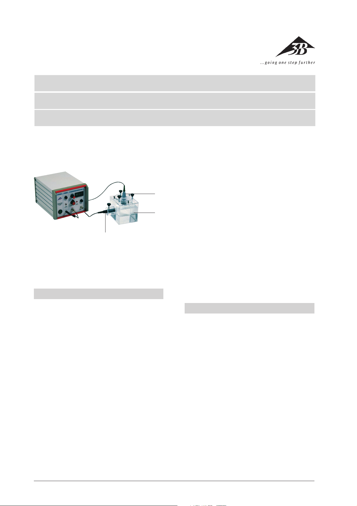
Ultrasound generator with accessories for the DebyeSears experiment and for demonstrating standing ultrasonic waves.
Safety instructions
Before switching on the ultrasound generator and accessories, carefully read the following instructions for
the sake of your safety and for the safety of the equipment.
• The slits in the device are for ventilation and must
be kept clear to avoid overheating the equipment.
It is recommended that the device be placed on its
own stand (also included).
• Before switching on the device make sure that it is
adjusted to the mains voltage you intend to use.
Make sure that you keep within the operating specifications.
• Never try to push objects through the slits in the
device since this could cause short circuits or electric shocks.
• Only use 3B’s own ultrasound transducer with the
“PROBE” connection. Be careful, voltages may be
as high as 70 V.
• Do not use the ultrasound transducer for a lengthy
period without contact to fluids. Otherwise the
transducer may overheat and be destroyed.
• Do not turn on the U10007 laser diode if there are
1 Laser diode
2 Test vessel
3 Ultrasonic transducer
people standing in the beam. This is a class II laser
with power < 1 mW. Do not look into the beam or
aim it at other people or animals.
• Beware: high-powered ultrasound! Do not use the
probe on people or animals.
Contents
1. Introduction ............................................ 7
2. Components ............................................ 7
2.1 Ultrasound generator - operating elements 7
2.2 Set-up for test container 8
2.3 Lens on glass slide 8
2.4 Laser diode (U10008) 8
3. Experiment procedure .............................. 8
3.1 General instructions for experiments 8
3.2 Debye-Sears effect 9
3.3 Projection of standing ultrasonic waves 9
4. Technical details ..................................... 10
1.1. Ultrasound generator 10
4.2. Ultrasonic transducer 10
4.3. Test vessel 10
6
Page 2
1. Introduction
In 1932 Debye and Sears demonstrated for the first time
how light is refracted when passing through a fluid excited to high-frequency oscillation. The maxima and
minima in density act here like the grid elements of
an optical diffraction grating. The grating constant
corresponds to the ultrasonic wavelength and is thus
dependent on the frequency of the ultrasound and the
speed of sound in the medium through which the
sound is travelling.
The CW (continuous wave) generator with its accompanying broad-band ultrasound transducer, along with
an adjustable test vesseland its integrated laser holder,
mean that it is possible for the first time to demonstrate this phenomenon to schoolchildren and college
students alike using simple and compact equipment.
The equipment can demonstrate both frequency dependence (with four different frequencies) and the ultrasonic wavelength in various fluids, allowing the
speed of sound in the medium to be calculated.
It is also possible to project standing ultrasonic waves
by inserting an optical lens between the laser source
and the ultrasonic waves. The waves are then projected
by the diverging laser beam.
2. Components
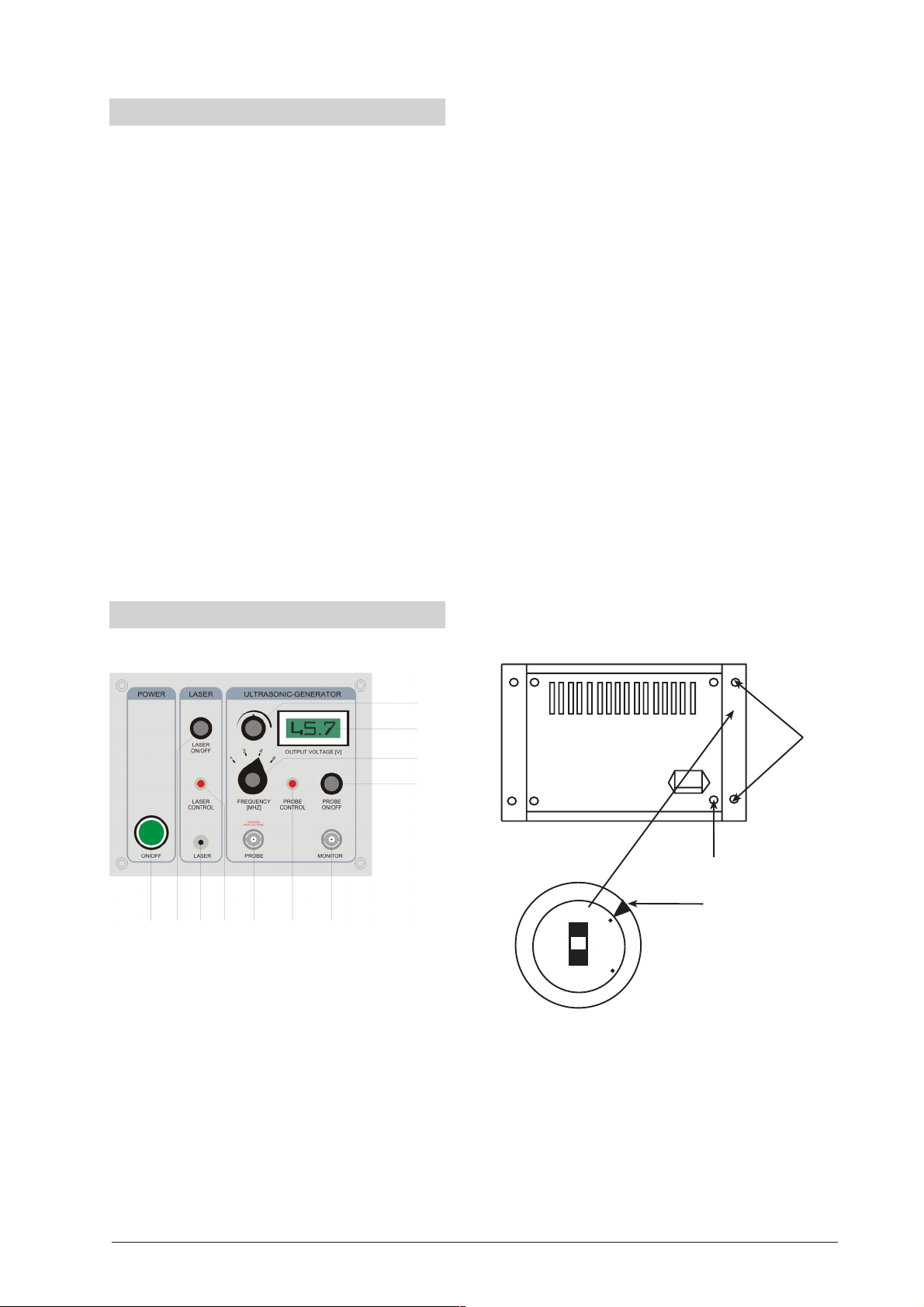
2.1 Ultrasound generator - operating elements
The ultrasound generator generates continuous highpower ultrasonic waves (CW = continuous wave). The
voltage bmcan be adjusted between 5 and 65 V. There
is an LCD display for the voltage output bl. The transmitted voltage can be switched off separately 8. The
frequency can be set to one of four frequencies (1, 2, 4
or 8 MHz) 9. An additional monitor output 7 allows
the output frequency to be determined precisely with
the aid of an oscilloscope or a frequency counter. A
suitable output 3is provided to supply power to a
laser diode. This can also be switched off separately
2.
Adjustment of mains voltage
The ultrasound generator can operate with 230 V or
115 V mains voltage. A voltage selector switch is situated on the rear of the casing and is hidden beneath
the covering to the right of the rear panel. A screwdriver is used to alter the switch setting (see illustration). If the mains voltage is altered, the fuse needs to
be changed to suit the mains voltage. A T630 mA fuse
should be used with 115 V mains voltage and a T315
mA fuse for 230 V mains.
Warning:
Unplug from the mains before altering the mains setting.
No voltage may be applied to the device while making
the adjustment,
1 2 3 4 5 6 7
1 Mains switch
2 On/off switch for laser
3 Connector socket for laser
4 Control light for laser
5 Connector socket for ultrasonic transducer
6 Control light for ultrasonic transducer
7 Monitor output
8 On/off switch for ultrasound
9 Frequency selection switch
bl Voltage display
bm Voltage setting
bm
bl
9
8
1
2
115
230
1 Remove the two screws from the rear panelling and take off
the panel. The voltage selector switch is revealed.
2 Fuse
115 V 630 mA
230 V 315 mA
3 An arrow indicates the voltage that is currently set. Adjust using
a screwdriver inserted into the slit.
3
7
Page 3

2.2 Set-up for U10008 test container
1 Adjustment screw for changing the angle of the transducer
2 Lid
3 Transducer holder
4 Ultrasonic transducer (supplied with U10006)
5 Securing screw for laser diode
6 Slot for lens holder
7 Laser holder
8 Securing screw for ultrasonic transducer
9 Glass vessel
The following illustration shows how the lens should
be properly placed in the test container.
1
2
3
4
5
6
7
8
9
2.4 Laser diode (U10007)
Standing ultrasonic waves are generated in a special
container. It allows the angle of incidence of the waves
to be set precisely to the perpendicular by means of a
special holder for the ultrasound transducer.
The test vessel consists of a glass vessel with a lid and a
holder for the transducer, three adjustment screws to
set the alignment for the standing wave and a laser
holder perpendicular to the axis of the waves which also
has a holder for a lens so that the ultrasonic waves and
the Debye-Sears effect can be projected.
2.3 Lens on a glass slide
A plane-convex lens is attached to a rectangular slide.
This is inserted into the slot in the laser holder of the
test container for experiments involving projection.
1 2 3
1 Plano-convex lens (f=100 cm)
2 Glass slide
3 Grip
1 2 3 4
1 Laser beam window
2 Laser module jacket
3 Plug for connecting to ultrasound generator
4 Connecting lead
Class II laser diode for demonstrating the Debye-Sears
effect and projecting ultrasonic waves for use with the
ultrasound generator and test container.
3. Experiment procedure
3.1 General instructions for experiments
Pay attention to the following instructions if the experiment is to work:
• Use water that contains as little air as possible since
air bubbles disturb both the ultrasound field and
the refraction of the laser beam.
• Any air bubbles around the probe should be re-
moved.
• Allow for the maximum distance between the test
container and the projection screen.
• When no measurements are being made, the ul-
trasound should be switched off so that the test
fluid does not heat up.
8
Page 4

• For precise measurements, also measure the tem-
perature and include this in the comparison.
• When using high voltage at any frequency and when
the transducer is properly aligned, at least 3 orders
of diffraction should be visible.
• The projection experiment is much more sensitive
to the angle of the transducer than the refraction
experiment. Thus for this experiment the conditions
for generating standing waves need to be adhered
to more precisely.
3.2 Debye-Sears effect
The wavelength of the ultrasonic waves in the Debye-Sears
experiment (photo left, 4 MHz
in water) can be determined
for various different test fluids
(water, glycerine, cooking oil).
This means measuring the distance s between the ultrasound transducer and the refracted image. Then the number of orders of refraction N
and distance between the -nth
and +nth bands x can be de-
termined. Since the wavelength of the laser light
λ
L
known then:
λ
2N s
(1)
λ
s
gives the ultrasonic wavelength
L
=
x
λ
. The individual vari-
s
ables can be calculated as in the following diagram.
λ
L
λ
s
s
N = 3
N = 2
N = 1
N = 0
N = -1
N = -2
N = -3
The ultrasonic frequency n is measured at the monitor
socket. Then the speed of sound c in the fluid is given
by:
is
2. Glycerine
v = 4 MHz, s = 2.90 m, N = 2, x = 1.6 cm,
λ
= 650 nm
L
therefore: λ = 471.2 µm, c = 1885 m/s
(Table: 1900 m/s at 25°C)
3.3 Projection of standing ultrasonic waves
Direct projection of ultrasonic waves can be an interesting extension to
the experiment. The
sound wave is projected by inserting a
convex lens into the
laser beam so that
the beam is diverged. The density
variations in the
standing wave then
appear as light and
dark regions on the
projection screen
(see photograph
right). To determine
the wavelength from
the diffraction image and the geometry involved, as well as the focal length
f of the lens in air (100 mm in this case), corrections due
to the glass walls of the vessel and the test fluid also
need to be considered.
N = 6
N = 5
N = 4
N = 3
x
N = 2
g
1
a1a
x
The light refraction method as described in 3.2 is thus
g
2
2
s
N = 1
N = 0
better suited for calculating the wavelength precisely.
The precise equation for
λ
in the projection experi-
s
ment is:
gna
1g1
f
−−
(3)
2
==
λ
s
N
x
sf
−−+−
n
FL
ggnaa
12g12
+
n
FL
(2) c =
λ
ν
s
Example results:
1. Water
v = 4 MHz, s = 2.90 m, N = 4, x = 4.1 cm,
therefore:
λ
= 367.8 µm, c = 1471 m/s
s
(Table: 1480 m/s at 20°C)
λ
= 650 nm
L
The distance a1 between the glass wall towards the lens
and the distance a2 can be approximated as half the
internal width of 9.6 cm. The thickness of the glass g
and g2 is about 4 or 5 mm. The refractive indices nFL for
the test fluid and ng for the glass may be measured or
taken from tables.
9
1
Page 5

N is the number of bright maxima and x the separation between them.
The speed of sound in the medium can now be calculated once again from the measured frequency n using equation (2).
Note:
With the U10008 test vessel it is only possible to set up
a good projection of the standing ultrasonic wave at a
frequency of 4 MHz. At 2 MHz and especially at 1 MHz
ultrasonic waves reflected from the bottom of the container are superimposed destructively on the impinging ultrasonic beam. Only for 4 MHz waves is the difference in the path length of the order of several wavelengths. At 8 MHz the amplitude of the emitted wave
is too small and also the absorption is much greater
(the absorption coefficient is proportional to the square
of the frequency). This means that no clear standing
waves are produced.
Example results:
Water:
a1 = a2 = 4.8 cm, f = 10 cm, nFL = 1.33, ng = 1.45,
s =3.03 m, n = 4 MHz, x = 8.9 cm, g1 = 5 mm, g2 = 4 mm
therefore: λ = 397 µm, c = 1590 m/s
(Table: 1480 m/s at 20°C)
4. Technical details
4.1 Ultrasound generator (U10006)
Frequency: 1, 2, 4, 8 MHz adjustable
Output signal: Sine wave, continuously adjustable
between 5 Vpp to approximately
65 Vpp. Can be switched off.
Red control light
Display: 3-digit LCD, one decimal place,
height of digits 10 mm
Monitor signal: TTL, Frequency signal
Laser output: 3 V DC, max. 300 mW at socket
5.5 mm outer Ø, 2.5 mm inner Ø,
Can be switched off.
Red control light
Dimensions: 256 x 86 x 156 mm
Mains voltage: 115/230 V, 50/60 Hz
Power consumption: max. 60 VA; 5 VA minimum power
(laser and ultrasound switched
off)
Fuse: T 315 mA (230 V) / T 630 mA (115 V)
Ultrasonic transducer
Probe diameter: 27 mm
Active surface area: 2 cm²
Cable length: 1 m with BNC socket
4.2 Test vessel (U10008)
Test vessel: 100 x 100 x 120 mm
Volume: 900 ml approx.
Laser holder: 17 mm internal diameter
Transducer holder: adjustable, designed for the
supplied transducer
Lens on glass slide
Lens slide: 76 mm x 26 mm Glass slide with
roughened gripping surface
Lens: Plano-convex, f = 100 mm
(in air), 16 mm Ø
4.3 Laser diode (U10007)
Beam spot: < 6 mm at 3 m
Wavelength: 650 nm
Power: < 1 mW, laser safety class II
Supply voltage: 3 V DC
Current consumption: max. 35 mA
Connecting plug: 1 m cable with plug of 5.5 mm
outer Ø, 2.5 mm inner Ø
Dimensions: 80 mm x 17 mm Ø
3B Scientific GmbH • Rudorffweg 8 • 21031 Hamburg • Germany • www.3bscientific.com • Technical amendments are possible
10
 Loading...