

Page 1
3B SCIENTIFIC
Bedienungsanleitung
06/10 ALF
®
PHYSICS
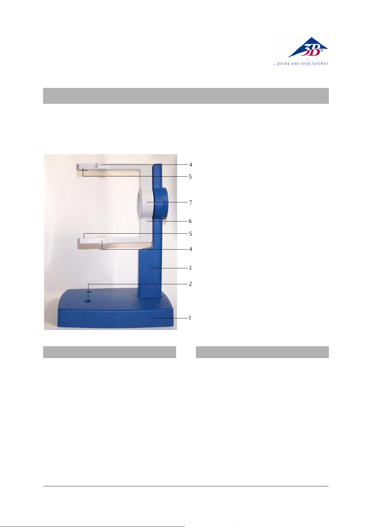
Röhrenhalter D U191001
1 Grundplatte
2 Bohrungen für Helmholtz-
Spulen
3 Stativsäule
4 Fixierschieber
5 Klemmen für Röhren
6 Spanngabel
7 Aufnahme für Röhren und
Optisches Analogon
1. Sicherheitshinweise
Beim Betrieb der Röhren können am Anschlussfeld
berührungsgefährliche Spannungen und Hochspannungen anliegen.
• Schaltungen nur bei ausgeschalteten Versor-
gungsgeräten vornehmen.
• Röhren nur bei ausgeschalteten Versorgungs-
geräten ein- und ausbauen.
2. Beschreibung
Der Röhrenhalter dient zur Aufnahme des gesamten Röhrenprogramms S U191501 - U19171 und
deren Zubehörteile, wie Helmholtzspulen U191051
und Zusatzspule U19106 sowie des Optischen Analogons U19172.
Der Röhrenhalter besteht aus einer robusten
Grundplatte mit Stativsäule sowie einer um 360°
drehbaren Spanngabel aus hitzebeständigem,
hochisoliertem Kunststoff zur Aufnahme der Glühkatodenröhren. Die Röhren werden in federnden
Klemmen mit Fixierschiebern befestigt. In der
Grundplatte befinden sich zwei Bohrungen für ein
Paar der Helmholtzspulen im „Helmholtz-Abstand“
zur Erzeugung eines homogenen Magnetfeldes. Der
Röhrenhalter steht rutschfest auf drei Gummifüßen.
1
Page 2
3. Technische Daten
Abmessungen: ca. 230 x 175 x 320 mm3
Abstand der
Bohrungen: ca. 76 mm
Masse: ca. 1,5 kg
4. Bedienung
4.1 Einsetzen und Entnahme einer Glühkatodenröhre
• Röhren nur bei ausgeschalteten Versorgungs-
geräten ein- und ausbauen.
• Fixierschieber ganz zurück schieben.
• Glühkatodenröhre in die Klemmen einsetzen.
• Mittels der Fixierschieber Glühkatodenröhre in
den Klemmen sichern.
• Zum Entnehmen der Glühkatodenröhre Fixier-
schieber wieder zurück schieben und Röhre
entnehmen.
4.2 Aufbau der Helmholtzspulen (U191051)
• Glühkatodenröhre wie oben beschrieben in
den Halter einsetzen.
• Helmholtzspulen mit den Anschlüssen nach
außen weisend in die Bohrungen stecken. Dazu Steckhülse am Stativstab nach oben schieben, Stab schräg in die Bohrungen einführen.
• Hülse in die Bohrung drücken und so Spulen
fixieren.
4.3 Aufbau der Zusatzspule (U19106)
• Spule auf der oberen Gabel platzieren.
• Fixierschieber über die Lippe der Zusatzspule
schieben und Spule so fixieren.
4.4 Aufbau des Optischen Analogons (U10172)
• Aluminiumscheibe mit Kreuzgitter von hinten
in die Stativsäule einsetzen.
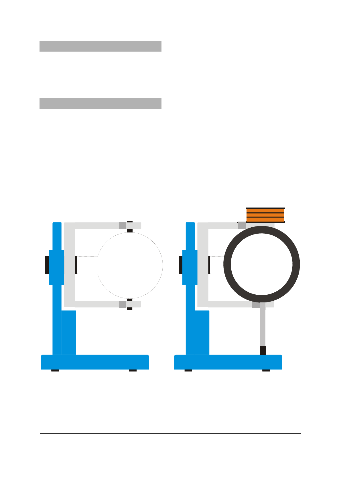
Fig. 1 Aufbau einer Röhre (links); einer Röhre, der Helmholtzspulen und der Zusatzspule (rechts)
3B Scientific GmbH • Rudorffweg 8 • 21031 Hamburg • Deutschland • www.3bscientific.com
Technische Änderungen vorbehalten
© Copyright 2010 3B Scientific GmbH
Page 3
3B SCIENTIFIC
Instruction sheet
06/10 ALF
®
PHYSICS
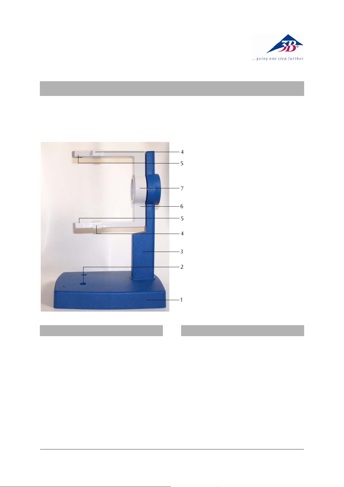
Tube Holder D U191001
1 Base plate
2 Holes for inserting Helm-
holtz coils
3 Stanchion
4 Retaining slider
5 Clamping jaws for tubes
6 Fork
7 Stock for tubes and optical
analogue equipment
1. Safety instructions
When operating tubes, the terminals may be live to
high voltages that are dangerous to touch.
• Do not modify circuits unless all power sup-
plies are turned off.
• Do not mount or remove tubes unless all
power supplies are turned off.
2. Description
The tube holder accommodates all tubes of the
series U191501 - U19171 and their accessories,
such as the Helmholtz Coils U191051 and Auxiliary
Coil U19106 plus the Optical Analogue equipment
U19172.
The tube holder consists of a robust base plate with
an upright stanchion and a fork-shaped holder for
hot cathode tubes that can be rotated by 360° and
is made of heat-resistant, highly insulating plastic.
The tubes are secured into sprung clamps with
retaining sliders. Two holes are bored in the base
plate to accommodate a pair of Helmholtz coils at
the “Helmholtz separation distance” for generating
a uniform magnetic field. The tube holder rests on
three non-slip rubber feet.
1
Page 4
3. Technical data
Dimensions: 230x175x320 mm3 approx.
Separation of
holes for coils: 76 mm approx.
Weight: 1.5 kg approx.
4. Operation
4.1 Setting up and removing hot cathode tubes
• Tubes should not be mounted or removed
unless all power supplies are disconnected.
• Push the jaw clamp sliders on the stanchion of
the tube holder right back so that the jaws
open.
• Push the bosses of the tube into the jaws.
• Push the jaw clamps forward on the stanchions
to secure the tube within the jaws.
• To remove the tube, push the jaw clamps right
back again and take the tube out of the jaws.
4.2 Setting up the Helmholtz coils (U191051)
• Place the tube in the holder as described
above.
• Insert the Helmholtz tubes into the holes with
the connections facing outwards. Push the
sleeves on the rod upwards and insert the rod
at an angle.
• Push the sleeves into the holes to secure the
coils.
4.3 Setting up the auxiliary coil (U19106)
• Place the coil on the upper fork.
• Push the retaining slider over the lip of the
auxiliary coil to secure the coil in place.
4.4 Setting up the optical analogue equipment
(U10172)
• Insert the aluminium disc with the grating into
the stanchion from behind.
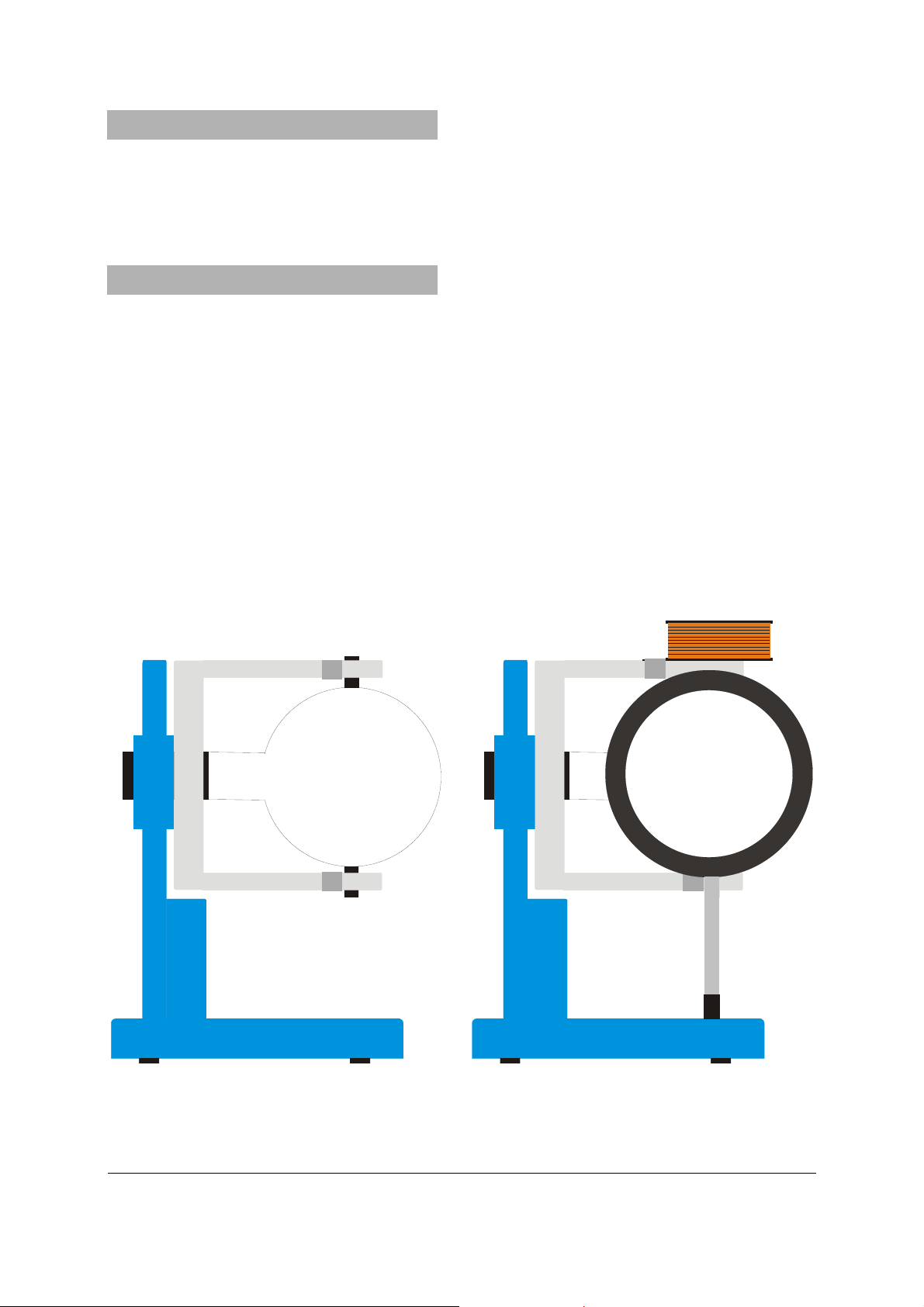
Fig. 1 Setting up a tube (left), a tube, the Helmholtz coils and the auxiliary coil (right)
3B Scientific GmbH • Rudorffweg 8 • 21031 Hamburg • Germany • www.3bscientific.com
Subject to technical amendments
© Copyright 2010 3B Scientific GmbH
Page 5

3B SCIENTIFIC
Instructions d'utilisation
06/10 ALF
®
PHYSICS
Porte-tube D U191001
1 Plaque de base
2 Alésages pour bobines
Helmholtz
3 Colonne de support
4 Coulisseau de fixation
5 Pinces pour le tube
6 Fourche de serrage
7 Logement du tube et équi-
valent optique
1. Consignes de sécurité
Des tensions et hautes tensions dangereuses peuvent apparaître à hauteur du champ de connexion
pendant l'utilisation des tubes.
• Ne procéder à des câblages que lorsque les
dispositifs d'alimentation sont éteints.
• Ne monter et ne démonter le tube que lorsque
les dispositifs d'alimentation sont éteints.
2. Description
Le porte-tube peut recevoir toute la gamme de
tubes U191501 - U19171 et leurs éléments accessoires, tels les bobines Helmholtz U191051 et la bobine supplémentaire U19106 ainsi que l'équivalent
optique U19172.
Le porte-tube est constitué d'une plaque de base
robuste avec colonne de support ainsi que d'une
fourche de serrage orientable à 360° et fabriquée
en matière plastique résistante à la chaleur et
hautement isolée, destinée à recevoir le tube thermoionique. Le tube est fixé entre deux pinces à
coulisseau. La plaque de base présente deux alésages pour loger une paire de bobines Helmholtz
dans l'écart « de Helmholtz » permettant de générer un champ magnétique homogène. Le portetube est monté sur des pieds en caoutchouc antidérapants.
1
Page 6

3. Caractéristiques techniques
Dimensions : env. 230 x 175 x 320 mm3
Ecart des alésages : env. 76 mm
Masse : env. 1,5 kg
4. Manipulation
4.1 Montage et démontage d'un tube thermoionique
• Ne monter et ne démonter le tube que lorsque
les dispositifs d'alimentation sont éteints.
• Repousser complètement en arrière le coulis-
seau de fixation.
• Insérer le tube thermoionique entre les pinces.
• Avec le coulisseau, fixer le tube entre les pin-
ces.
• Pour démonter le tube, ramener le coulisseau
en arrière et dégager le tube.
4.2 Montage des bobines Helmholtz (U191051)
• Insérer le tube thermoionique dans le porte-
tube, comme décrit ci-dessus.
• Enficher les bobines dans les alésages en veil-
lant à ce que les connexions soient orientées
vers l'extérieur. Pour cela, glisser vers le haut le
manchon enfichable sur la barre de support et
introduire la barre de biais dans les alésages.
• Enfoncer le manchon dans l'alésage et fixer
ainsi les bobines.
4.3 Montage de la bobine supplémentaire
(U19106)
• Placer la bobine sur la fourche supérieure.
• Glisser le coulisseau au-delà de la lèvre de la
bobine et fixer ainsi cette dernière.
4.4 Montage de l'équivalent optique (U10172)
• Insérer le disque en aluminium avec le réseau
à croix par derrière dans la colonne de support.
Fig. 1 Montage d'un tube (à gauche); d'un tube, des bobines Helmholtz et de l'équivalent optique (à droite)
3B Scientific GmbH ▪ Rudorffweg 8 ▪ 21031 Hamburg ▪ Allemagne ▪ www.3bscientific.com
Sous réserve de modifications techniques
© Copyright 2010 3B Scientific GmbH
Page 7

3B SCIENTIFIC
Istruzioni per l'uso
06/10 ALF
®
PHYSICS
Portatubi D U191001
1 Piastra di base
2 Fori per bobine di
Helmholtz
3 Montante dello stativo
4 Cursore di fissaggio
5 Morsetti per tubi
6 Forcella di serraggio
7 Alloggiamento per tubi ed
equivalente ottico
1. Norme di sicurezza
Durante il funzionamento dei tubi, sul pannello di
collegamento possono essere presenti tensioni e
alte tensioni che rendono pericoloso il contatto.
• Eseguire i collegamenti soltanto con gli
apparecchi di alimentazione disinseriti.
• Montare e smontare i tubi soltanto con gli
apparecchi di alimentazione disinseriti.
2. Descrizione
Il portatubi è utilizzabile con l'intera gamma di
tubi U191501 - U19171 e con i relativi accessori,
come le bobine di Helmholtz U191051 e la bobina
supplementare U19106, nonché l'equivalente
ottico U19172.
Il portatubi è costituito da una piastra di base
robusta con montante dello stativo e da una
forcella di serraggio girevole a 360° realizzata in
plastica resistente al calore ad elevato isolamento
per l'alloggiamento dei tubi a catodo caldo. I tubi
vengono fissati in morsetti elastici con cursori di
fissaggio. Nella piastra di base sono presenti due
fori per una coppia di bobine di Helmholtz a
"distanza di Helmholtz" per la generazione di un
campo magnetico omogeneo. Il portatubi è dotato
di tre piedini antiscivolo in gomma.
1
Page 8

3. Dati tecnici
Dimensioni: ca. 230 x 175 x 320 mm3
Distanza tra i fori: ca. 76 mm
Peso: ca. 1,5 kg
4. Comandi
4.1 Inserimento e rimozione di un tubo a
catodo caldo
• Montare e smontare i tubi soltanto con gli
apparecchi di alimentazione disinseriti.
• Far scorrere i cursori di fissaggio
completamente all'indietro.
• Inserire il tubo a catodo caldo nei morsetti.
• Bloccare il tubo a catodo caldo nei morsetti
mediante i cursori di fissaggio.
• Per estrarre il tubo, spingere di nuovo
all'indietro i cursori di fissaggio e rimuoverlo.
4.2 Montaggio delle bobine di Helmholtz
(U191051)
• Inserire il tubo a catodo caldo nel supporto
come descritto sopra.
• Innestare le bobine di Helmholtz nei fori con i
collegamenti rivolti verso l'esterno. Far
scorrere verso l'alto la spina a pressione sul
supporto dello stativo e introdurre l'asta
obliquamente nei fori.
• Spingere la spina nel foro e fissare la bobina.
4.3 Montaggio della bobina supplemen-tare
(U19106)
• Posizionare la bobina sulla forcella superiore.
• Far scorrere il cursore di fissaggio sopra il
bordo della bobina supplementare e fissarla in
questo modo.
4.4 Montaggio dell'equivalente ottico (U10172)
• Inserire il disco di alluminio con reticolo a
croce nel montante dello stativo dalla parte
posteriore.
Fig. 1 Montaggio di un tubo, (a sinistra), a tube, the Helmholtz coils and the auxiliary coil (a destra)
3B Scientific GmbH • Rudorffweg 8 • 21031 Amburgo • Germania • www.3bscientific.com
Con riserva di modifiche tecniche
© Copyright 2010 3B Scientific GmbH
Page 9

3B SCIENTIFIC
Soporte para tubos D U191001
Instrucciones de uso
06/10 ALF
®
PHYSICS
1 Placa base
2 Perforaciones para las
bobinas de Helmholtz
3 Columna soporte
4 Pinzas para tubos
5 Corredera de fijación
6 Horquilla de fijación
7 Alojamiento para los tubos
y para el equivalente óptico
1. Aviso de seguridad
Durante el funcionamiento de los tubos se pueden
generar tensiones peligrosas al contacto y altas
tensiones en el panel de conexiones.
• Las conexiones sólo se deben realizar con los
dispositivos de alimentación apagados.
• Los tubos sólo se deben insertar y extraer con
los dispositivos de alimentación apagados.
2. Descripción
El soporte para tubos sirve para alojar todo el
programa de tubos U191501 - U19171 y sus piezas
accesorias, tales como las bobinas de Helmholtz
U191051, la bobina adicional U19106 y el
equivalente óptico U19172.
El soporte para tubos consta de una placa base
robusta, de una columna soporte y una horquilla
de fijación, de material plástico, resistente al calor
y altamente aislado, que puede girar 360°, para
alojar los tubos de cátodo caliente. Los tubos se
sujetan por medio de pinzas suspendidas
elásticamente, con correderas de fijación. En la
placa base hay dos perforaciones para un par de
bobinas de Helmholtz, ubicadas a la distancia que,
en la configuración indicada por Helmholtz,
permite generar un campo magnético homogéneo.
El portatubo se apoya sobre tres pies de goma
antideslizante.
1
Page 10

3. Datos técnicos
Dimensiones: aprox. 230x175x320 mm3
Distancia entre
perforaciones: aprox.76 mm
Peso: aprox. 1,5 kg
4. Servicio
4.1 Insertar y extraer un tubo de cátodo
caliente
• Los tubos sólo se deben insertar y extraer con
los dispositivos de alimentación apagados.
• Desplace la corredera de fijación
completamente hacia atrás.
• Inserte el tubo de cátodo caliente en las
pinzas.
• A continuación, debe asegurar el tubo de
cátodo caliente en las pinzas mediante las
correderas de fijación.
• Para retirar el tubo de cátodo caliente, debe
volver a retroceder la corredera de fijación
antes de extraerlo.
4.2 Montaje de las bobinas de Helmholtz
(U191051)
• Inserte el tubo de cátodo caliente en el
soporte, como se describió anteriormente.
• Coloque las bobinas de Helmholtz en las
perforaciones, con las conexiones señalando
hacia afuera. A tal efecto, debe empujar el
manguito enchufable de la vara soporte hacia
arriba e introducir a continuación la vara
oblicuamente en las perforaciones.
• Introduzca el manguito en la perforación
aplicando presión y fije así las bobinas.
4.3 Montaje de la bobina adicional (U19106)
• Coloque la bobina en la horquilla superior.
• Empuje la corredera de fijación por encima del
labio de la bobina adicional y fije así la
bobina.
4.4 Montaje del equivalente óptico (U10172)
• Inserte el disco de aluminio, que presenta la
rejilla en cruz, por la parte posterior en la
columna soporte.
Fig. 1 Montaje de un tubo, (izquierdo); de un tubo, de las bobinas de Helmholtz y de la bobina adicional (derecha)
3B Scientific GmbH • Rudorffweg 8 • 21031 Hamburgo • Alemania • www.3bscientific.com
Se reservan las modificaciones técnicas
© Copyright 2010 3B Scientific GmbH
Page 11

3B SCIENTIFIC
Suporte de tubos D U191001
Instruções para o uso
06/10 ALF
®
FÍSICA
1 Placa base
2 Perfurações para bobinas
de Helmholtz
3 Coluna do apoio
4 Deslizante de fixação
5 Pinça para tubos
6 Garfo de tensão
7 Recepção dos tubos e
análogo ótico
1. Indicações de segurança
Durante a operação dos tubos podem surgir
tensões perigosas ao contato e altas tensões no
campo de conexão.
• Só efetuar ligações com os aparelhos de
alimentação elétrica desligados.
• Só montar ou desmontar os tubos com os
aparelhos de alimentação elétrica desligados.
2. Descrição
O suporte de tubos serve para a recepção de todo a
gama de tubos U191501 - U19171 e os seus
acessórios, como a bobina de Helmholtz U191051 e
a bobina adicional U19106 assim como o análogo
ótico U19172.
O suporte de tubos consiste numa placa base
robusta com eixo de pé de apoio assim como um
garfo tensor giratório em 360°, feito de matéria
plástica resistente ao calor e fortemente isolada,
para a recepção dos tubos catódicos
incandescentes. Os tubos são fixados com pinças
amortecidas e deslizantes de fixação. Na placa base
encontram-se duas perfurações para um par de
bobinas de Helmholtz numa "distância de
Helmholtz“ para a criação de um campo magnético
homogêneo. O suporte de tubos apoia-se
firmemente sobre três pés de borracha.
1
Page 12

3. Dados técnicos
Medidas: aprox. 230x175x320 mm3
Distância entre
perfurações: aprox. 76 mm
Massa: aprox. 1,5 kg
4. Utilização
4.1 Instalação e retirada de um tubo catódico
incandescente
• Só montar ou desmontar os tubos com os
aparelhos de alimentação elétrica desligados.
• Empurrar os deslizantes de fixação
completamente para trás.
• Instalar os tubos catódicos incandescentes nas
pinças.
• Fixar os tubos catódicos incandescentes nas
pinças por meio dos deslizantes de fixação.
• Para retirar o tubo catódico incandescente,
puxar o deslizante de fixação de volta e retirar
o tubo.
4.2 Montagem das bobinas de Helmholtz
(U191051)
• Instalar o tubo catódico incandescente no
suporte como descrito acima.
• Inserir as bobinas de Helmholtz com os
conectores virados para fora. Paralelamente,
levantar o cartucho de inserção na vara do pé
de apoio, inserir a vara inclinada na
perfuração.
• Pressionar o cartucho na perfuração e fixar
assim a bobina.
4.3 Montagem da bobina adicional (U19106)
• Colocar a bobina no braço superior do garfo.
• Empurrar o deslizante de fixação por cima do
extremo da bobina adicional e assim fixando-a.
4.4 Montagem do análogo ótico (U10172)
• Inserir a placa de alumínio com a grade de
cruzes por trás no eixo do pé de apoio.
Fig. 1 Montagem de um tubo, (esquerdo); de um tubo, das bobinas de Helmholtz e da bobina adicional (direita)
3B Scientific GmbH • Rudorffweg 8 • 21031 Hamburgo • Alemanha • www.3bscientific.com
Sob reserva de alterações técnicas
© Copyright 2010 3B Scientific GmbH
 Loading...