

Page 1
3B SCIENTIFIC
Instruction sheet
05/12 ALF
8
-
6
®
PHYSICS
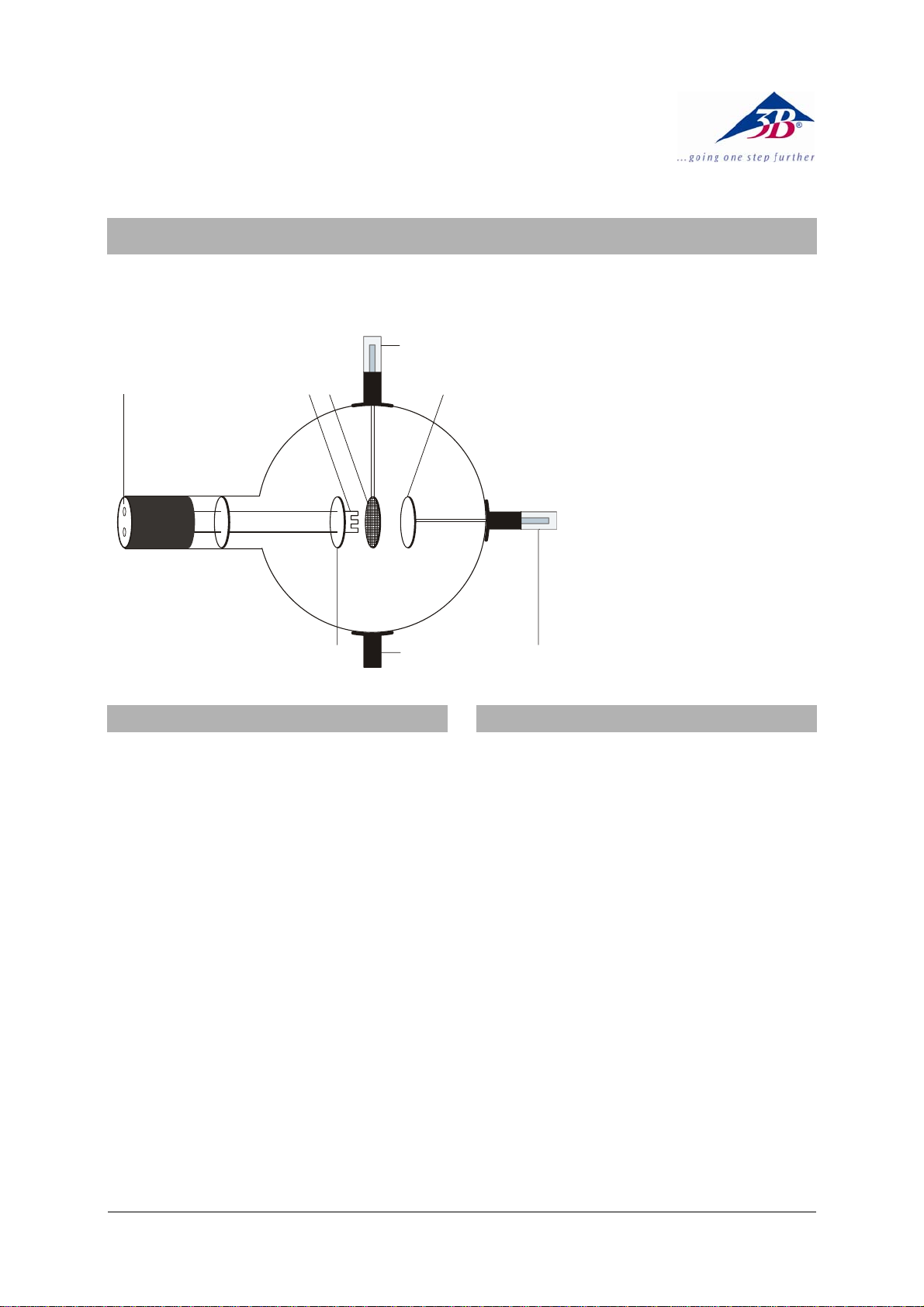
Triode D 1000647
5
4
3
1 Boss
2 4-mm plug for connecting
anode
3 Anode
4 Grid
5 Boss with 4-mm plug for
connecting grid
6 Heater filament
7 Cathode plate
8 4-mm sockets for connect-
ing filament and cathode
7
1. Safety instructions
Hot cathode tubes are thin-walled, highly
evacuated glass tubes. Treat them carefully as
there is a risk of implosion.
• Do not subject the tube to mechanical stresses.
• Do not subject the connection leads to any
tension.
• The tube may only be used with tube holder D
(1008507).
If voltage or current is too high or the cathode is
at the wrong temperature, it can lead to the tube
becoming destroyed.
• Do not exceed the stated operating parameters.
When the tube is in operation, the terminals of
the tube may be at high voltages with which it is
dangerous to come into contact.
• Only change circuits with power supply
equipment switched off.
• Only exchange tubes with power supply
equipment switched off.
When the tube is in operation, the stock of the
tube may get hot.
• Allow the tube to cool before dismantling.
The compliance with the EC directive on electromagnetic compatibility is only guaranteed
when using the recommended power supplies.
12
2. Description
The triode allows basic experiments to be performed using the Edison effect (thermionic effect), determining the negative charge of electrons, recording triode characteristics and generating cathode rays (model of an electron gun).
It also allows investigating the technical application of a triode as an amplifier and generating
undamped oscillations in LC circuits.
The triode is a highly evacuated tube with a pure
tungsten heater filament (cathode) and a round
metal plate (anode) with a wire grid between
them, all inside a clear glass bulb. The cathode,
anode and grid are all aligned parallel to one
another. This planar configuration corresponds
to the conventional symbol for a triode. A circular metal plate attached as a backing to the filament ensures that the electric field between the
anode and cathode is uniform.
1
Page 2

3. Technical data
Filament voltage: 7.5 V max.
Filament current: 3 A approx.
Anode voltage: 500 V max.
Anode current: U
400 V and U
A
U
0 V, IA 0.4 mA approx.
G
UG +8 V, I
U
G
-8 V, I
A
0.04 mA approx.
A
6.3 V
F
0.8 mA approx.
Grid voltage: ± 10 V max.
Glass bulb: 130 mm diam. approx.
Total length: 300 mm approx.
4. Operation
To perform experiments using the triode, the
following equipment is also required:
1 Tube holder D 1008507
1 DC power supply 500 V (115 V, 50/60 Hz)
1003307
or
1 DC power supply 500 V (230 V, 50/60 Hz)
1003308
1 Analogue multimeter AM51 1003074
Additionally recommended:
Protective Adapter, 2-Pole 1009961
4.1 Setting up the tube in the tube holder
• The tube should not be mounted or removed
unless all power supplies are disconnected.
• Push the jaw clamp sliders on the stanchion of
the tube holder right back so that the jaws open.
• Push the bosses of the tube into the jaws.
• Push the jaw clamps forward on the stan-
chions to secure the tube within the jaws.
• If necessary plug the protective adapter onto
the connector sockets for the tube.
4.2 Removing the tube from the tube holder
• To remove the tube, push the jaw clamps right
back again and take the tube out of the jaws.
5. Example experiments
5.1 Generation of charge carriers by a hot
cathode (thermionic effect) and determining the polarity of the charge carriers
so emitted
• Set up the circuit as in Fig. 1. Connect the
minus pole of the anode voltage to the 4-mm
socket marked with a minus.
• Set the anode voltage U
When the grid voltage U
to 400 V.
A
is 0 V the anode cur-
G
rent is about 0.4 mA.
• Set the grid voltage to +10 V resp. -10 V.
If the voltage of the grid is positive with respect
to the anode, the anode current I
is considera-
A
bly increased. If the grid is negative with respect
to the cathode the anode current decreases.
A heater filament generates charge carriers.
Current flows between the cathode and the anode. The charge carriers must be of negative
polarity because when the grid is negative with
respect to the cathode the flow of current decreases and when it is positive, the flow of current increases.
5.2 Recording triode characteristics
• Set up the circuit as in Fig. 1. Connect the
minus pole of the anode voltage to the 4-mm
socket marked with a minus.
• I
– U
characteristics: for constant grid volt-
A
A
ages, determine the anode current as a
function of the anode voltage and plot the
values in a graph (refer to Fig. 2).
• I
– U
A
characteristics: for constant anode
G
voltages, determine the anode current as a
function of the grid voltage and plot the values in a graph (refer to Fig. 2).
5.3 Generating cathode rays
• Set up the circuit as in Fig. 3 so the grid and
cathode form a diode. Connect the minus
pole of the anode voltage U
to the 4-mm
A
socket marked with a minus.
• Raise the anode voltage U
from 10 V to 80 V
A
and measure the current flowing at the anode.
The current decreases at higher voltages since
the positive potential of the grid causes it to capture electrons causing an increase in the current
passing through the grid itself. Voltages greater
than 100 V can lead to the destruction of the grid.
Electrons accelerated by higher potentials between the grid and the cathode can be detected
beyond the grid (cathode rays). Increasing the
voltage leads to higher currents which indicates a
greater number of electrons being accelerated.
5.4 Triode amplifier
Also required:
1 AC/DC power supply 12 V (115 V, 50/60 Hz)
1001006
or
1 AC/DC power supply 12 V (230 V, 50/60 Hz)
1001007
1 Resistor 1 MΩ
1 Oscilloscope
• Set up the circuit as in Fig. 4. Connect the
minus pole of the anode voltage to the 4-mm
socket marked with a minus.
• Apply an anode voltage U
of about 300 V.
A
The oscilloscope is used to demonstrate the
amplification in the signal across the resistor.
• Repeat the experiment using a variety of
resistors.
Lower AC voltages at the grid lead to greater
changes in voltage across a resistor connected
in circuit with the anode. The amplification gain
increases with the size of the resistor.
1
Page 3

5.5 Generation of undamped LC oscillations
Also required:
1 Helmholtz pair of coils D 1000644
2 Barrel foot 1002834
1 Capacitor 250 pF or 1000 pF
1 Oscilloscope
Warning! When the anode voltage is
switched on, the metal parts of the coils are
live. Do not touch!
• Only change circuits with power supply
equip-ment switched off.
• Set up the circuit as in fig. 5.
• Place the coils side by side as near one
another as possible.
DC POWER SUPPLY 0 ... 500 V
3
0
0
0
0
2
4
0
0
0
0
1
5
0
0
0
VV VV
3
0
0
2
4
0
0
1
5
0
0
4
6
2
0
3
8
0
• Apply an anode voltage U
of about 300 V.
A
• Observe the undamped oscillations on the
screen of the oscilloscope.
• Rotate one of the coils to demonstrate that
that the occurance and amplitude of the oscillations depends on the relative position of
the two coils. Touch the coils only at the insulated parts!
• Vary the anode voltage U
between 100 and
A
500 V and observe that the amplitude of the
oscillations does not increase in direct pro-
portion to U
• Carry out an experiment of the same kind
.
A
without capacitators so that the capacitance
of the oscillating circuit is formed only by the
self capacitance of the conductor.
6
9
1
2
0 ... 500 V 0 ... 50 V
U
A
U
I
A
G
U
F
0 ... 12 V0 ... 8 V
Fig. 1 Demonstration of anode current and determination of the polarity of the charge carriers
3
Page 4

Fig. 2 Triode characteristics
DC POWER SUPPLY 0 ... 500 V
3
0
0
0
0
2
4
0
0
0
0
1
5
0
0
0
3
0
0
2
4
0
0
1
5
0
0
4
6
2
0
8
VV VV
6
3
0
9
1
2
Fig. 3 Generating cathode rays
0 ... 500 V 0 ... 50 V
U
A
0 ... 12 V0 ... 8 V
U
F
I
A
4
Page 5

0
C
DC POWER SUPPLY 0 ... 500 V
3
0
0
0
0
2
4
0
0
0
0
1
5
0
0
3
0
0
2
4
0
0
1
5
0
0
0
4
6
2
0
VV VV
6
9
3
8
1
0
2
0 ... 500 V 0 ... 50 V
Fig. 4 Triode amplifier
0 ... 12 V0 ... 8 V
U
A
U
F
I
A
1 M
Ω
- 10 V A
DC POWER SUPPLY 0 ... 500 V
3
0
0
0
0
2
4
0
0
0
0
1
0
VV VV
3
0
0
2
4
0
0
1
5
0
0
0
4
6
2
5
0
0
6
9
3
8
1
2
0
1000 pF
0 ... 500 V 0 ... 50 V
U
A
ZZ
AA
U
F
0 ... 12 V0 ... 8 V
Fig. 5 Generation of undamped LC oscillations
A TELTRON Product from UK3B Scientific Ltd. ▪ Suite 1 Formal House, Oldmixon Crescent ▪ Weston-super-Mare
Somerset BS24 9AY ▪ Tel 0044 (0)1934 425333 ▪ Fax 0044 (0)1934 425334 ▪ e-mail uk3bs@3bscientific.com
Technical amendments are possible
© Copyright 2012 3B Scientific GmbH
Page 6

 Loading...