

Page 1
3B SCIENTIFIC® PHYSICS
Gas Triode D 1000653
Instruction sheet
12/12 ALF
5
68
7
34
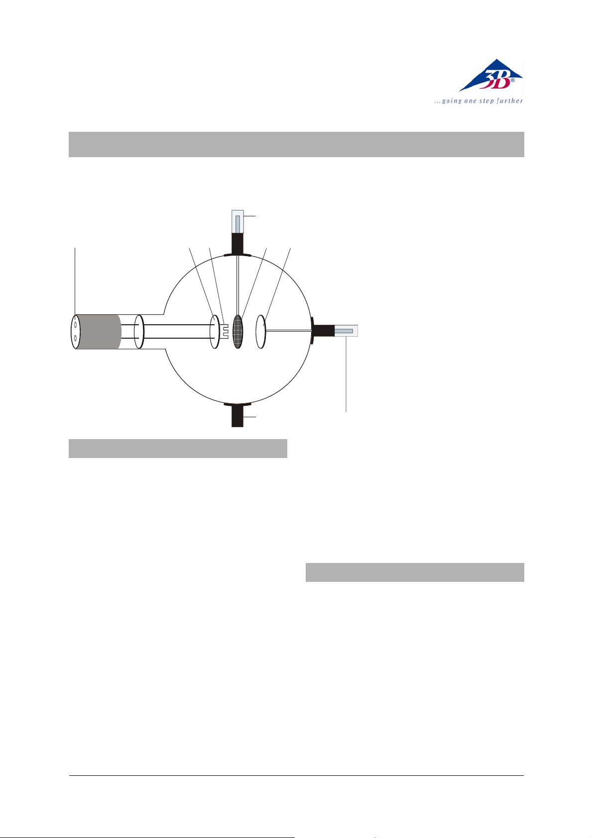
1 Boss
2 4-mm plug for connect-
ing anode
3 Anode
4 Grid
5 Boss with 4-mm plug for
connecting grid
6 Heater filament
7 Cathode plate
8 4-mm sockets for heater
filament and cathode
-
12
1. Safety instructions
Hot cathode tubes are thin-walled, highly
evacuated glass tubes. Treat them carefully as
there is a risk of implosion.
• Do not subject the tube to mechanical
stresses.
• Do not subject the connection leads to any
tension.
• The tube may only be used with tube holder
D (1008507).
If voltage or current is too high or the cathode is
at the wrong temperature, it can lead to the tube
becoming destroyed.
• Do not exceed the stated operating parame-
ters.
When the tube is in operation, the terminals of
the tube may be at high voltages with which it is
dangerous to come into contact.
• Only change circuits with power supply
equipment switched off.
• Only exchange tubes with power supply
equipment switched off.
When the tube is in operation, the stock of the
tube may get hot.
• Allow the tube to cool before dismantling.
Use of the equipment over long periods and
involving hefty gas discharges can cause loss of
material from the electrodes, which is deposited
on the glass of the tube itself resulting in darkening of the surface.
The compliance with the EC directive on electromagnetic compatibility is only guaranteed
when using the recommended power supplies.
2. Description
The gas triode allows recording of the IA – U
A
characteristic of a thyratron, observation of excited and non-excited discharge and of the discontinuous transfer of energy by helium atoms
in inelastic collision with free electrons.
The gas triode is a helium-filled tube with a pure
tungsten heater filament (cathode) and a round
metal plate (anode) with a wire grid between
them, all inside a clear glass bulb. The cathode,
anode and grid are all aligned parallel to one
another. This planar configuration corresponds
to the conventional symbol for a triode. A circular metal plate attached as a backing to the filament ensures that the electric field between the
anode and cathode is uniform.
1
Page 2

3. Technical data
Gas filling: Helium
Filament voltage: ≤ 7.5 V AC/DC
Anode voltage: max. 500 V DC max.
Anode current: 10 mA typ. at U
= 300 V
a
Grid voltage: max. 30 V
Glass bulb: 130 mm diam. approx
Length of tube: 260 mm approx.
4. Operation
To perform experiments using the gas triode the
following equipment is also required:
1 Tube holder D 1008507
1 DC Power supply 500 V (@115 V) 1003307
or
1 DC Power supply 500 V (@230 V) 1003308
2 Analogue multimeter AM50 1003073
Additionally recommended:
Protective Adapter, 2-Pole 1009961
4.1 Setting up the tube in the tube holder
• The tube should not be mounted or removed
unless all power supplies are disconnected.
• Push the jaw clamp sliders on the stanchion
of the tube holder right back so that the jaws
open.
• Push the bosses of the tube into the jaws.
• Push the jaw clamps forward on the stan-
chions to secure the tube within the jaws.
• If necessary plug the protective adapter onto
the connector sockets for the tube.
4.2 Removing the tube from the tube holder
• To remove the tube, push the jaw clamps
right back again and take the tube out of the
jaws.
5. Example experiments
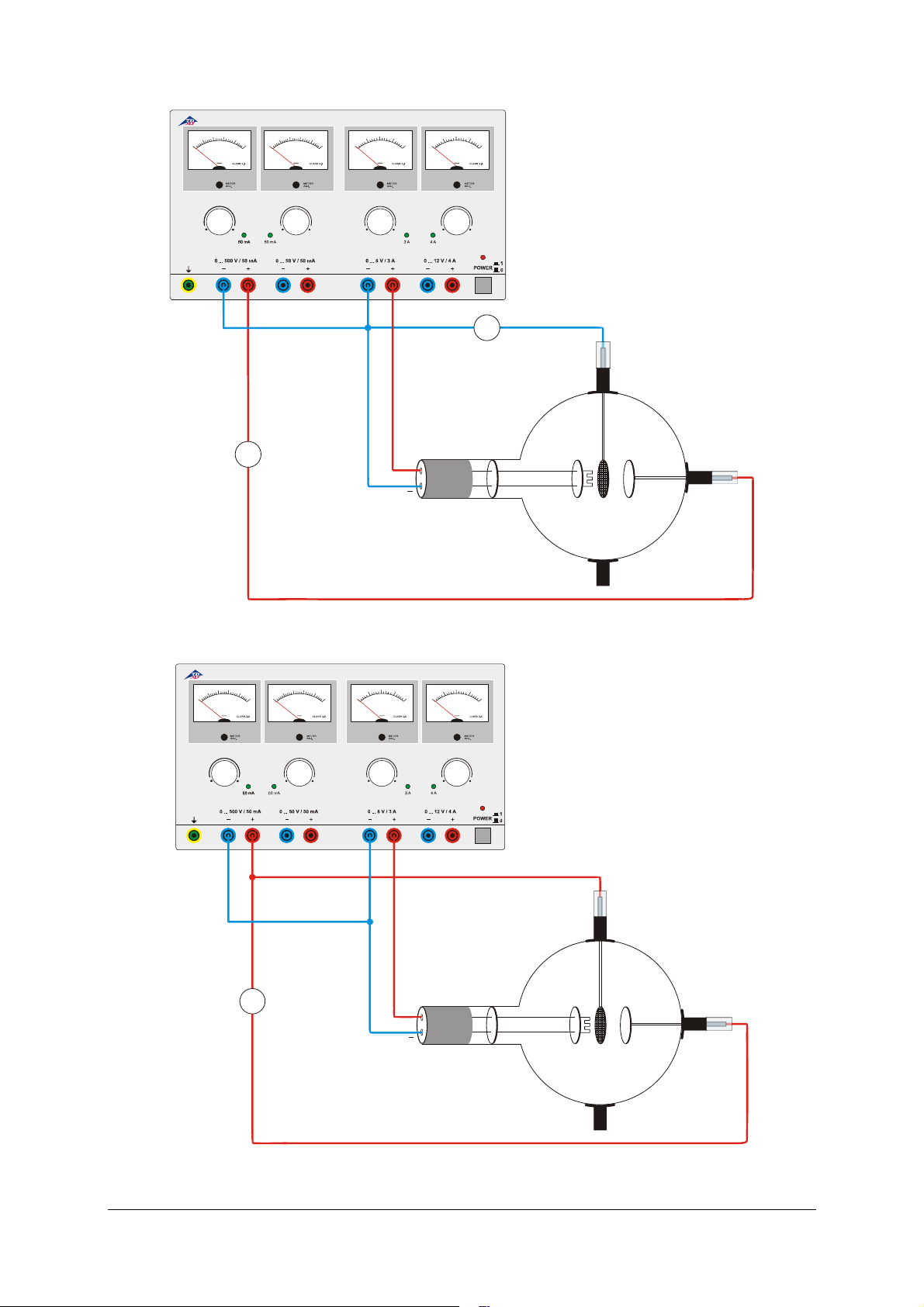
5.1 Discharge, evidence of positive charge
carriers
• Set up the circuit as in fig. 1.
• To demonstrate the existence of positive
charge carriers (He
at a maximum heater filament voltage U
measure the current I
+
ions) for gas discharge
taking note of the
G
,
F
sign.
5.2 Non-self-sustaining discharge
• Set up the circuit as in fig. 2.
• Record a characteristic curve of I
U
(= UG) for various filament voltages U
A
against
A
(5
F
V …7.5 V).
At about 25 V the anode current I
increases
A
considerably in the gas triode. This increase is
accompanied by the appearance of a blue luminescence. It is apparent that there are many
more charge carriers transporting charge than in
the vacuum triode (since there are He
+
ions as
well as thermal electrons).
5.3 Self-sustaining discharge
• Set up the circuit as in fig. 3.
• Gradually increase the anode voltage U
and determine the striking voltage U
for the
S
A
gas discharge.
• Reduce the anode voltage U
again until the
A
self-sustaining discharge ceases. Record
this extinguishing voltage U
.
E
5.4 Simplified Franck-Hertz-set-up
Experiment for demonstrating discontinuous
energy emission resulting from inelastic collisions between between electrons and helium
atoms. The electrons have to travel through a
decelerating reverse-potential field between the
grid and anode, so that they only arrive at the
anode if they possess sufficient kinetic energy.
Only then do they contribute to the current I
A
between anode and ground.
• Set up the circuit as in fig. 4.
• For a reverse polarity U
raise the accelerating potential U
to 70 V and measure the anode current I
• Plot a graph of the anode current as a func-
of 6 V, gradually
R
from 0 V
A
.
A
tion of the accelerating voltage.
Up to an accelerating potential of about 24 V,
the anode current increases but then it drops
suddenly. As the accelerating potential is further
increased the current increases once again but
after another 20 V or so it drops again.
A plot of the anode current should exhibit two
clear maxima. If this is not perceptible, the filament voltage should be lowered somewhat.
2
Page 3
DC POWER SUPPLY 0 ... 500 V
3
0
0
0
0
2
4
0
0
0
0
1
5
0
0
0
3
0
0
2
4
0
0
1
5
0
0
4
6
2
0
8
VV VV
6
9
3
1
0
2
0 ... 500 V 0 ... 50 V
U
A
I
A
Evidence of positive charge carriers
Fig. 1
3
0
0
0
0
2
4
0
0
0
0
1
5
0
0
0
0
VV VV
0 ... 12 V0 ... 8 V
U
F
I
G
DC POWER SUPPLY 0 ... 500 V
3
0
0
2
4
0
0
1
5
0
4
6
2
0
8
6
9
3
1
0
2
0 ... 500 V 0 ... 50 V
U
A
I
A
Evidence for positive charge carriers
Fig. 2
0 ... 12 V0 ... 8 V
U
F
3
Page 4

DC POWER SUPPLY 0 ... 500 V
3
0
0
0
0
2
4
0
0
0
0
1
5
0
0
3
0
0
2
4
0
0
1
5
0
0
0
4
6
2
0
6
3
8
0
VV VV
9
1
2
0 ... 500 V 0 ... 50 V
U
A
I
A
Fig.3 Self-sustaining discharge
3
0
0
0
0
2
4
0
0
0
0
1
0
VV VV
0 ... 12 V0 ... 8 V
DC POWER SUPPLY 0 ... 500 V
5
0
0
0
5
0
3
0
0
2
4
0
0
1
4
6
2
0
8
6
9
3
1
0
2
0 ... 500 V 0 ... 50 V
Fig. 4 Franck-Hertz set-up
0 ... 12 V0 ... 8 V
U
A
U
R
I
A
U
F
A TELTRON Product from UK3B Scientific Ltd. ▪ Suite 1 Formal House, Oldmixon Crescent ▪ Weston-super-Mare
Somerset BS24 9AY ▪ Tel 0044 (0)1934 425333 ▪ Fax 0044 (0)1934 425334 ▪ e-mail uk3bs@3bscientific.com
Technical amendments are possible
© Copyright 2012 3B Scientific GmbH
 Loading...