

Page 1
3B SCIENTIFIC
Instruction sheet
12/12 ALF
-
®
PHYSICS
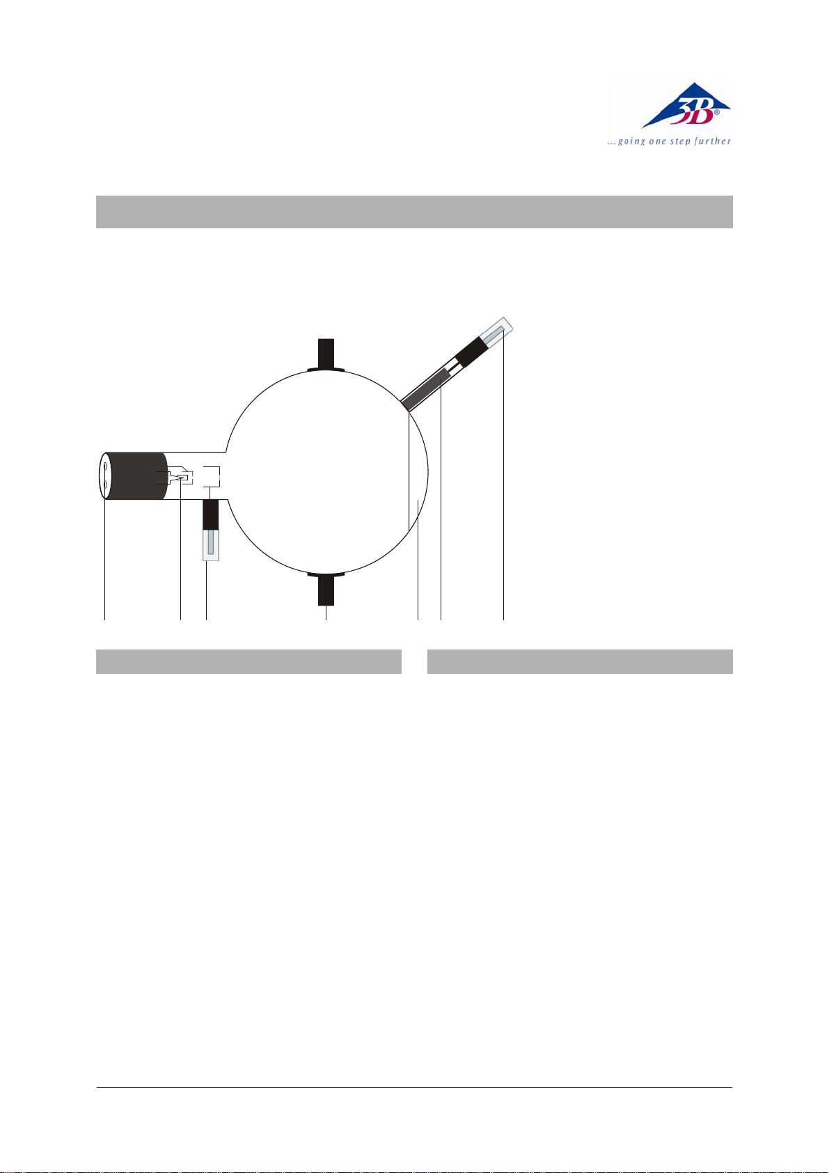
Perrin Tube D 1000650
1 4mm sockets connected to
cathode filament and heating
2 Heater filament
3 4mm plug for connecting
anode
4 Boss
5 Fluorescent screen
6 Faraday cage
7 4mm plug connected to
Faraday cage
1 4 7
Hot cathode tubes are thin-walled, highly
evacuated glass tubes. Treat them carefully as
there is a risk of implosion.
• Do not subject the tube to mechanical
stresses.
• Do not subject the connection leads to any
tension.
• The tube may only be used with tube holder D
(1008507).
If voltage or current is too high or the cathode is
at the wrong temperature, it can lead to the tube
becoming destroyed.
• Do not exceed the stated operating parameters.
• Only change circuit with power supply equip-
ment switched off.
• Only exchange tubes with power supply
equipment switched off.
When the tube is in operation, the stock of the
tube may get hot.
• If necessary, allow the tube to cool before
dismantling.
The compliance with the EC directive on electromagnetic compatibility is only guaranteed
when using the recommended power supplies.
23 56
1. Safety instructions
The Perrin tube serves to demonstrate the negative
polarity of electrons and to estimate the specific
electron charge e/m by magnetic deflection into a
Faraday cage, which is connected to an electroscope. It is also possible to investigate the deflection of electrons in two perpendicular magnetic
alternating fields and to demonstrate the effects, for
example by generating Lissajous figures.
The Perrin tube is a highly evacuated tube with
an electron gun, consisting of a pure tungsten
heater filament and a cylindrical anode contained
in a clear glass bulb, partly coated with a fluorescent screen. The electrons emitted by the electron gun form a narrow circular beam that can be
seen as a spot on the fluorescent screen. A glass
tube with a Faraday cage is set on the glass bulb
at about 45° to the undeflected beam.
2. Description
1
Page 2

3. Technical data
Filament voltage: ≤ 7.5 V AC/DC
Anode voltage: 2000 V - 5000 V
Anode current: typ. 1.8 mA at
U
= 4000 V
A
Beam current: 4 µA at U
= 4000 V
A
Glass bulb: 130 mm dia. approx.
Total length: 260 mm approx.
4. Operation
are visible as a round spot.
• Set up the Helmholtz coils and use them to
deflect the beam so that it falls within the
end of the Faraday cage. Alternatively the
beam can be deflected using a magnet
placed on one of the stanchions of the tube
holder.
The electroscope will open to indicate the presence of a charge.
• Turn off the voltage to the heater filament
and the anode.
The electroscope remains open.
If the charge on the Faraday cage were due to
the cathode beam being some kind of wave
To perform experiments using the Perrin tube,
the following equipment is also required:
1 Tube holder D 1008507
1 High voltage power supply 5 kV (115 V, 50/60 Hz)
1003309
or
1 High voltage power supply 5 kV (230 V, 50/60 Hz)
1003310
1 Helmholtz pair of coils S 1000611
1 DC Power Supply 20 V, 5 A (115 V, 50/60 Hz)
1003311
or
1 DC Power Supply 20 V, 5 A (230 V, 50/60 Hz)
1003312
1 Electroscope 1001027
1 Analogue multimeter AM50 1003073
Additionally recommended:
Protective Adapter, 2-Pole 1009961
4.1 Setting up the tube in the tube holder
• The tube should not be mounted or removed
unless all power supplies are disconnected.
• Push the jaw clamp sliders on the stanchion
of the tube holder right back so that the jaws
open.
• Push the bosses of the tube into the jaws.
• Push the jaw clamps forward on the stan-
chions to secure the tube within the jaws.
• If necessary plug the protective adapter onto
the connector sockets for the tube.
4.2 Removing the tube from the tube holder
• To remove the tube, push the jaw clamps
right back again and take the tube out of the
jaws.
5. Example experiments
5.1 Evidence of the particle nature of cath-
ode beam and establishment of their polarity
• Set up the experiment as in fig. 1.
• Apply a voltage to the anode between 3 kV
and 5 kV.
radiation, the charge should disappear when the
filament ceases to radiate. Because the experiment shows that the charge remains on the
cage when the filament is cold, the conclusion
must be that the beam comprises some constituent of matter which is electrically charged.
These particles are called electrons.
The negative polarity of the cathode beam can
be demonstrated if the electroscope is charged
by rubbing a plastic or a glass rod (so that they
are negatively and positively charged respectively).
5.2 Estimation of the specific electron charge e/m
• Set up the experiment as in fig. 3.
When the electron beam is deflected into the
Faraday cage, the following applies to the spe-
cific charge e/m:
⋅
2
e
m
can be read out directly, the curvature radius
U
A
U
A
=
()
(1)
2
⋅
rB
r derives from the geometric data of the tube
(bulb diameter 13 cm, Faraday cage at 45° to
the beam axis) to r = 16 cm approx. (refer to fig.
2).
With the coils at Helmholtz-geometry and the
coil current I, the following applies to the mag-
netic flux density B of the magnetic field
3
2
4
⎞
⎛
B ⋅=⋅
=
⎟
⎜
5
⎠
⎝
n
⋅μ
0
⋅
R
with k = at good approximation 4.2 mT/A, n =
320 (no. of turns) and R = 68 mm (coil radius).
• Substitute U
, r and B in equation 1 and
A
calculate e/m.
5.3 Deflection in crossed magnetic alternating fields (Lissajous figures)
The following equipment is also required:
1 Auxiliary coil 1000645
1 AC/DC power supply 12 V, 3 A (115 V, 50/60 Hz)
1002775
or
1 AC/DC power supply 12 V, 3 A (230 V, 50/60 Hz)
1002776
On the fluorescent screen the cathode beams
IkI
(2)
2
Page 3

A
1 Function generator FG100 (115 V, 50/60 Hz)
1009956
or
1 Function generator FG100 (230 V, 50/60 Hz)
1009957
• Set up the experiment as in fig. 4.
• Place the auxiliary coil on the upper fork of
the tube holder. Push the jaw clamp over the
lip of the coil to secure it in place.
• Connect the auxiliary coil to the alternating
current source.
• Connect the Helmholtz coils to the function
generator and choose a sinusoidal signal.
• Apply a voltage to the anode between 3 kV
and 5 kV.
• Apply an alternating voltage up to 15 V to
the auxiliary coil and observe the horizontal
deflection.
• Set a frequency of e.g. 50 Hz at the function
generator, vary the amplitude of the sinesignal and observe the Lissajous figures on
the fluorescent screen.
A
Z
-
DC POWER SUPPLY 0 ... 5 kV
3
2
4
1
5
0
KV
U
U
F
0 ... 5 kV
Z
A
6
5
4
3
2
1
0
Fig. 1 Evidence of the particle nature of cathode beam and establishment of their polarity
r
Fig. 2 Definition of the curvature radius r
3
Page 4

A
DC POWER SUPPLY 0 ... 5 kV
3
2
4
1
0
A
5
KV
0 ... 5 kV
Z
I
A
Z
A
Fig. 3 Estimation of the specific electron charge e/m
Control Voltage
Frequency
Amplitude
0 V 10 V
12 VAC
2 A
FUNCTION GENERATOR
Offset Sweep
Start/Stop
Trig. In/Out Output In/Out
U
A
U
F
-
DC POWER SUPPLY 0 ... 5 kV
3
2
4
1
5
0
KV
0 ... 5 kV
A
U
A
Z
U
F
-
0...12 V
0...12 V / 3 A
+
Z
Fig.4 Deflection in crossed magnetic alternating fields (Lissajous figures)
A TELTRON Product from UK3B Scientific Ltd. ▪ Suite 1 Formal House, Oldmixon Crescent ▪ Weston-super-Mare
Somerset BS24 9AY ▪ Tel 0044 (0)1934 425333 ▪ Fax 0044 (0)1934 425334 ▪ e-mail uk3bs@3bscientific.com
Technical amendments are possible
© Copyright 2012 3B Scientific GmbH
 Loading...