

Page 1
3B SCIENTIFIC
Luminescence Tube D 1000648
Instruction sheet
12/12 ALF
-
®
PHYSICS
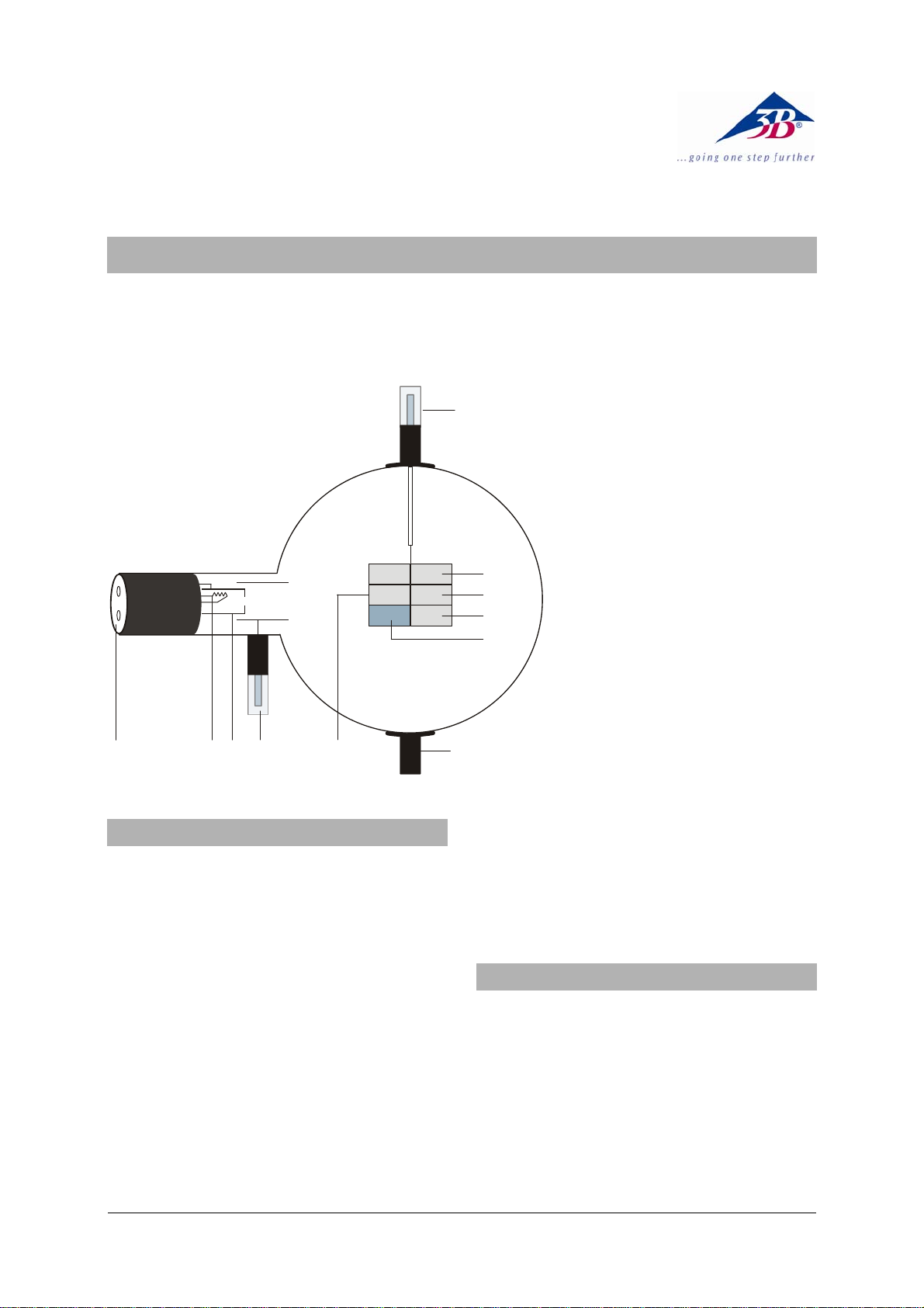
1 4-mm sockets for connecting
7
5.1
5.2
5.3
5.4
heater supply and cathode
2 Heater filament
3 Cathode
4 4-mm plug for connecting an-
ode
5 Luminescence screen
5.1 Zinc sulfide, activated with
silver
5.2 Yttrium vanadate, activated
with europium
5.3 Zinc sulfide, activated with
silver and cobalt
5.4 As 6.3 but graphite-coated back
to prevent heat radiation
6 Boss
7 4-mm plug for luminescence
screen
1345
Hot cathode tubes are thin-walled, highly evacuated glass tubes. Treat them carefully as there
is a risk of implosion.
• Do not subject the tube to mechanical
stresses.
• Do not subject the connection leads to any
tension.
• The tube may only be used with tube holder
D (1008507).
If voltage or current is too high or the cathode is
at the wrong temperature, it can lead to the tube
becoming destroyed.
• Do not exceed the stated operating parame-
ters.
• Only change circuits with power supply
equipment switched off.
• Only exchange tubes with power supply
equipment switched off.
2
1. Safety instructions
6
When the tube is in operation, the stock of the
tube may get hot.
• Allow the tube to cool before dismantling.
The compliance with the EC directive on electromagnetic compatibility is only guaranteed
when using the recommended power supplies.
2. Description
The luminescence tube serves to demonstrate
the luminescence of a phosphorous anode when
excited by electrons (cathodoluminescence) or
ultraviolet light (photoluminescence).
The luminescence tube is a highly evacuated
tube with an electron gun consisting of a pure
tungsten heater filament inside an apertured
“cathode can” and a cylindrical anode contained
in a clear glass bulb. A luminescence screen
with three mica flags with different phosphors is
mounted on a metal support.
1
Page 2

3. Technical data
Filament voltage: 6.3 V AC/DC (8.0 V max.)
Filament current: 1.8 A typical at U
= 6.3 V
F
Anode voltage: 2000 - 5000 V DC
Anode current: 180 µA typical at
U
= 4000 V
A
Screen current: 100 µA typical at
U
= 4000 V
S
Glass bulb: 130 mm diam. approx.
Total length: 260 mm approx.
Luminescence screen:
5.1: fluorescent blue, approx. 450 nm, medium decay time
5.2: fluorescent red, approx. 625 nm, medium short decay time
5.3: fluorescent green, approx. 510 nm fluorescent, approx. 515 nm phosphorescent,
long decay time
4. Operation
To perform experiments using the luminescence
tube, the following equipment is also required:
1 Tube holder D 1008507
1 High voltage power supply 5 kV (115 V, 50/60 Hz)
1003309
or
1 High voltage power supply 5 kV (230 V, 50/60 Hz)
1003310
1 Analogue multimeter AM51 1003074
1 High-pressure mercury vapour lamp 1000852
Spectrum tube power supply (115 V, 50/60 Hz)
1003195
or
Spectrum tube power supply (230 V, 50/60 Hz)
1003196
1 Infra-red light source
Additionally recommended:
Protective Adapter, 2-Pole 1009961
4.1 Setting up the tube in the tube holder
• The tube should not be mounted or removed
unless all power supplies are disconnected.
• Push the jaw clamp sliders on the stanchion
of the tube holder right back so that the jaws
open.
• Push the bosses of the tube into the jaws.
• Push the jaw clamps forward on the stan-
chions to secure the tube within the jaws.
• If necessary plug the protective adapter onto
the connector sockets for the tube.
4.2 Removing the tube from the tube holder
• To remove the tube, push the jaw clamps
right back again and take the tube out of the
jaws.
5.1 Excitation by cathode ray bombardment
• To better observe the afterglow effects
(phosphorescence), carry out the the last
step of the experiment in a darkened room.
• Set up the luminescence tube as shown in
fig.1.
• Connect both the screens and the anode to
earth for maximum safety.
• Set the voltage U
• Observe the luminescence.
The three phosphors fluoresce at different wavelengths (colours).
• Vary the voltage between 2000 V and 4000 V.
• Observe the change of the luminous phe-
nomenon.
While the intensity of the fluorescence varies
with the voltage, wavelength does not.
• With U
scope to view the emissions from each
phosphor.
Note that the emission from the red phosphor
comprises a number of discrete emission lines.
• Switch off the power supply and observe the
afterglow (phosphorescence).
The removal of the source of thermionic bombardment causes luminescence to cease. The
decay of emission from the phosphors is particularly apparent on the green phosphor.
5.2 Excitation by ultra-violet light
• Carry out the experiment in a darkened
room.
• Set up the luminescence tube as shown in
fig.2.
• Do not switch on the power supply.
Note that there is no visible photoluminescence
due to the ambient light levels.
• Illuminate the gun side of the screen with
ultra-violet light and note the initial time dependency of emission intensity.
The three phosphors fluoresce at the same
wavelength as when excited by cathode ray
bombardment.
• Vary the intensity of the ulta-violet light, ei-
ther by changing the distance between the
light source and the phosphor, or by interposing suitable filters.
While the intensity of the fluorescence varies
with the intensity and energy of the exciting radiation, wavelength does not.
• Remove the ultraviolet light and observe the
afterglow (phosphorescence).
The decay characteristic of the green phosphor
appears longer than was observed after removal
of cathode ray bombardment. The reason for
this is that the phosphorescence of this material
is quenched by infra-red radiation. When the
filament supply is switched off there remains
5. Example experiments
at 4000 V use a hand held spectro-
A
to about 3500 V.
A
2
Page 3

sufficient infra-red emission from the cooling
filament to partially quench phosphorescence.
• Set the voltage to about 4500 V and note
the current flowing (typically 0.02 µA due to
leakage on or through the glass bulb).
• Illuminate the phosphors with ultra-violet
light and note that there is no change in current.
Since there is no change in current, it is clear
that the emission from the phosphorous materials is due to excitation processes and not to
ionisation.
DC POWER SUPPLY 0 ... 5 kV
3
2
KV
4
5
0 ... 5 kV
1
0
5.3 Phosphorescence and quenching
• Remove all connecting leads from the tube
(refer to fig. 3).
• Set up a ultra-violet light source so that the
gun side of the screen can be illuminated.
• Set up a infra-red light source so that the
backside of the screen can be illuminated.
• Illuminate the phosphors with ultra-violet
light until the green phosphor has built up to
full intensity.
• Switch off the ultra-violet light source and
immediately switch on the infra-red light
source.
The phosphorescence of the unprotected half of
the green phosphor is quenched while the other
half remains unaffected.
U
A
U
F
-
Fig. 1 Excitation by cathode ray bombardment
3
Page 4

DC POWER SUPPLY 0 ... 5 kV
3
2
4
1
0
5
KV
0 ... 5 kV
U
A
I
A
-
Fig. 2 Excitation by ultraviolet light
-
IR UV
UV
Fig. 3 Phosphorescence and quenching
A TELTRON Product from UK3B Scientific Ltd. ▪ Suite 1 Formal House, Oldmixon Crescent ▪ Weston-super-Mare
Somerset BS24 9AY ▪ Tel 0044 (0)1934 425333 ▪ Fax 0044 (0)1934 425334 ▪ e-mail uk3bs@3bscientific.com
Technical amendments are possible
© Copyright 2012 3B Scientific GmbH
 Loading...