

Page 1
3B SCIENTIFIC
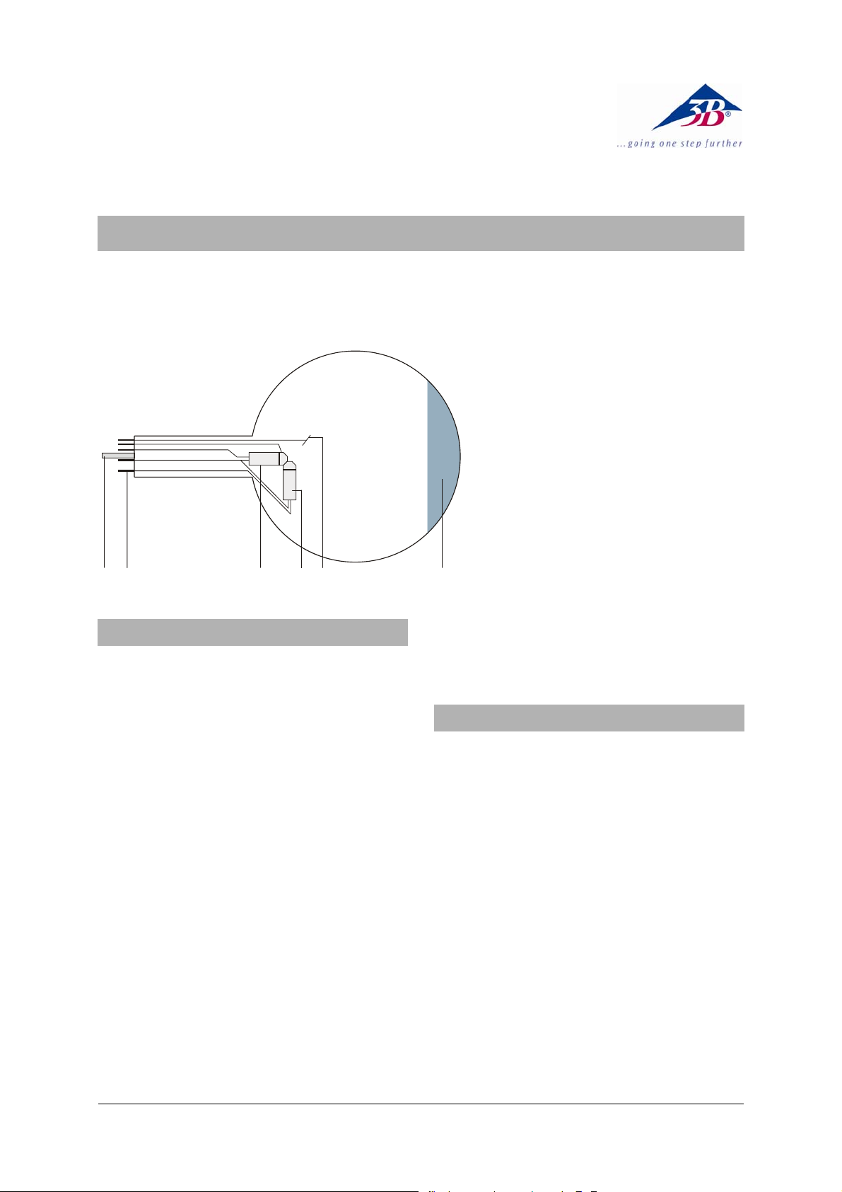
Dual Beam Tube S 1000622
Instruction sheet
12/12 ALF
®
PHYSICS
1 Guide pin
2 Connection pins
3 Axial electron gun
4 Perpendicular electron gun
5 Deflector plate
6 Fluorescent screen
12 3 4 65
1. Safety instructions
Hot cathode tubes are thin-walled, highly
evacuated glass tubes. Treat them carefully as
there is a risk of implosion.
• Do not subject the tube to mechanical stresses.
• Do not subject the cable connected with the
anode to any tension.
• The tube may only be used with tube holder S
(1014525).
If voltage or current is too high or the cathode is
at the wrong temperature, it can lead to the tube
becoming destroyed.
• Do not exceed the stated operating parameters.
When the tube is in operation, the terminals of
the tube may be at high voltages with which it is
dangerous to come into contact.
• Only use safety experiment leads for con-
necting circuits.
• Only change circuits with power supply
equipment switched off.
• Only exchange tubes with power supply
equipment switched off.
When the tube is in operation, the stock of the
tube may get hot.
• Allow the tube to cool before dismantling.
The EC directive on electromagnetic compatibility is only guaranteed when using the recommended power supplies.
2. Description
The dual beam tube can be used to determine
the specific charge e/m from the diameter of the
path followed by electrons fired into the tube
from a perpendicularly mounted gun with a vertically aligned magnetic field and observation of
the spiral path followed by electrons fired axially
into a co-axial magnetic field.
The dual beam tube is a partly evacuated electron tube, filled with helium at low pressure and
equipped with both axial and perpendicular electron guns. The electron beams are perpendicular to one another and a common deflector plate
is provided for both guns. The electron beam
source is an oxide cathode heated indirectly via
a heating coil. The electron paths show up as a
fine, slightly greenish beam due to impact excitation of the helium atoms.
1
Page 2

3. Technical data
R
μ
=
Filament voltage: 7.5 V AC/DC max.
Anode voltage: 100 V DC max.
Anode current: 30 mA max.
Deflector voltage: 50 V DC max
Glass bulb: 130 mm dia. approx.
Total length: 260 mm approx.
Gas filling: Helium at 0.1 torr
pressure
4. Operation
To perform experiments using the dual beam
tube, the following equipment is also required:
1 Tube holder S 1014525
1 Power supply 500 V (115 V, 50/60 Hz) 1003307
or
1 Power supply 500 V (230 V, 50/60 Hz) 1003308
1 Helmholtz pair of coils S 1000611
1 Analogue multimeter AM50 1003073
4.1 Setting up the tube in the tube holder
The tube should not be mounted or removed
unless all power supplies are disconnected.
• Press tube gently into the stock of the holder
and push until the pins are fully inserted. Take
note of the unique position of the guide pin.
4.2 Removing the tube from the tube holder
• To remove the tube, apply pressure with the
middle finger on the guide pin and the thumb
on the tail-stock until the pins loosen, then
pull out the tube.
5. Example experiments
5.1 Determination of e/m
An electron of charge e moving at velocity v perpendicularly through a magnetic field B experiences a force F that is perpendicular to both B
and v and the magnitude of which is given by:
evBF =
This causes the electron to follow a circular
electron path in a plane perpendicular to B. The
centripetal force for an electron of mass m is
2
F ==
mv
evB
which implies
v
B =
m
tesla
e
R
Rearranging the equation gives
v
e
m
=
BR
If the beam is subjected to a known magnetic
field of magnitude B, and v and R are both calculated then the ratio e/m can be determined.
The law of conservation of energy means that
the change in kinetic energy plus the change in
potential energy of a charge moving from point 1
to point 2 is equal to zero since no work is performed by external forces.
1
⎛
⎜
2
⎝
1
⎞
2
− eUeUmvmv
2
2
()
⎟
1
2
⎠
0
=−+
12
The energy of an electron in the dual beam tube
is given by:
1
=
A
2
mveU
2
By solving for v and replacing it in the equation
v
e
m
=
BR
the following emerges
2
U
e
m
A
=
22
RB
The term e/m is the specific charge of an elec-
tron and has the constant value (1.75888 ±
0.0004) x 10
11
C/kg.
5.1.1 Determination of B
The Helmholtz coils have a diameter of 138 mm
and give rise to a magnetic flux in Helmholtz
configuration as given by
I
tesla
H
and
262
where
HB
= (4.17 x 10⁻³)
0
−
1039.17
IB
⋅=
H
I is the current in the Helmholtz coils.
H
The following are also true
U
m
e
2
H
A
22
RI
H
U
A
=
kI
2
R
5
1015.1 ⋅⋅=
and
5.1.2 Determination of R
Referring to the diagram Fig. 1, the beam
emerges from the electron gun at C travelling
along the axis of the tube. The electron is then
deflected in a circular path with the tube axis
forming a tangent. The centre of this circle is at
B and it lies in the plane of DCD’ about 2 mm
behind the plane of EE’.
222
DCBCACBCAB ⋅−+= 2
2
Page 3

222
+
AC
ABBCR
22
⎡
2
=
R
⎢
⎢
⎣
⎤
+
yx
⎥
2
y
⎥
⎦
====
DC
2
yx
y
22
B
EA
D
2 mm
C
D’
E’ A’
Fig. 1 Derivation of R
R
x
y
2y
• Connect up the tube as in Fig. 3.
• Dim the room lighting.
• Assure the correct positioning of the Helm-
holtz coils in Helmholtz configuration.
• Set the heater voltage U
to 7 V and wait
F
about 1 minute for the heater temperature to
achieve thermal stability (see remarks in
section 7).
• Set the anode voltage U
age
U
= 0 V).
P
• Set the current in the coils I
to 90 V (plate volt-
A
so that the
H
deviated beam passes through point A on
the edge of the fluorescent screen of the
tube. Simultaneously focus the beam using
a plate voltage
• Mark point A on the tube using a felt-tip pen.
• Increase U
U
of no more than 6 V.
P
and set I
A
so that the deflected
H
beam always passes through A. Enter all the
values into a table.
U
in volts IH in amps I
A
2
H
90
100
110
120
• Increase I
so that the deflected beam al-
H
ways passes through point E and enter the
values in a corresponding table.
• Mark point E on the tube using a felt-tip pen.
• Plot the graphs of the values from both ta-
bles
• Use a vernier calliper to measure the diame-
ters AA’, EE’ and distance AE.
• Complete the table and calculate R².
AE
mm
x =
AE+
2 mm
2
x
mm
2
2y =
EE’
mm
y =
EE’ /
2 mm
y
mm
• Replace the values in the equation
U
e
m
A
22
RI
H
and calculate a mean value for
5
1015.1 ⋅⋅=
e/m.
5.2 Deflection in a circular path and the determination of e/m
• Connect up the tube as in Fig. 4.
• Assure the correct positioning of the Helm-
holtz coils in Helmholtz configuration.
• Set the anode voltage U
voltage
• Set the current in the coils I
U
= 0 V).
P
to 100 V (plate
A
so that the
H
deflected beam moves in a circular path with
the plane AA’ tangential to it.
It is practical in this instance to observe the
beam from above, from where it appears as a
straight line and can be focused using
mximum of 6 V.
Note: the axial non-linearity of the beam has the
effect of pushing the beam out of the plane of
the electron gun. In order to obtain more accurate results, the tube should be turned within the
brace that holds it so that the circular path is in
the plane of the gun.
so that plane AA’ makes a good tangent with the
I
should also be modified
H
path. A slight angle to the axis of the tube is
tolerable. The beam travels in a slightly spiralling path instead of an accurate circle.
• Increase U
and set I
A
so that the plane AA’
H
always forms a tangent to the deflected
beam. Tabulate
I
against U
H
and plot the
A
graph.
• Evaluate R = AE/2 and R² = AE²/4 like in
experiment 5.1.
• Replace the values in the equation
U
e
m
A
22
RI
H
and calculate a mean value for
5
1015.1 ⋅⋅=
e/m.
2
2
U
to a
P
2
R
mm
2
3
Page 4

5.3 The effect of an axial magnetic field
• Connect up the tube as in Fig. 5.
• Place one coil into the groove of the tube
holder from the front so that it encircles the
screen and connect it to the 12 V output of
the power supply.
• Set the anode voltage U
V (plate voltage
• Gradually increase the coil current I
U
P
With only one axial velocity vector
to no more than 60
A
= 0 V).
.
H
v
the axial
a
non-linearity of the beam is corrected and coincides with the true axis of the field.
• Mark the position of the beam with a felt-tip
pen.
• Set I
to 1.5 A and increase U
H
that a second velocity vector
gradually so
P
v
affects the
p
beam.
• View the beam end-on through the coil.
The beam path turns into a helix. The beam no
longer goes around the axis of the field but returns to a different position along the axis after
every loop.
6. Errors in the results
1. The circular beam path in experiment 5.2 is
visible because of photo-emission. The energy
involved in this process is lost and never replaced. This means that the beam actually tends
to follow a spiral path instead of a circle. For a
fixed radius
R and a real circle U
² would be
A/IH
larger than the values that we measure. For this
reason the error in the value of
e/m is always on
the negative side. Nevertheless results can be
achieved that are accurate to within 20%.
2. In experiments where the beams are de-
flected into semi-circular paths as in experiment
5.1 results are larger then the published value.
Points A and E, through which the beam is deflected, lie outside the homogeneous region of
the Helmholtz coils so that the magnetic flux is
reduced at these points. For a fixed radius
U
and a truly homogeneous field
² would be
A/IH
R
smaller than the values we measure. For this
reason the error in the value of
e/m is always on
the positive side. Nevertheless results can be
achieved that are accurate to within 20%.
7. Remarks
Fig. 2 Helical path of the deflected beam
Reverse the polarity of the magnetic field B
•
by reversing that of the Helmholtz coils and
observe what happens to the beam.
• Change the anode voltage and observe its
effect on the helical path of the beam. Then
restore the voltage to 60 V.
1. Limiting of anode current: to avoid an exces-
sive degree of emission of positive ions towards
the electron emitting chemicals of the cathode,
the anode current should be limited to below 20
mA wherever possible. Higher current may be
tolerated for a short time but over long periods it
reduces the lifespan of the tube.
2. Thermal stability of the cathode: for the same
reason, you should avoid starting the electron
gun when the cathode is cold and only just heating up.
3. Focussing the beam: Small voltages
plied to the deflector plates enable the beam to
be focussed. Voltages greater than 6 V cause
results to deteriorate.
U
ap-
P
4
Page 5

DC POWER SUPPLY 0 ... 500 V
A
A
3
0
0
0
0
2
4
0
0
0
0
1
5
0
0
0
3
0
0
2
4
0
0
1
5
0
0
4
6
2
0
8
6
3
0
VV VV
9
1
2
A
Z
A
Z
Fig. 3 Determining e/m using the axial electron gun
0 ... 500 V 0 ... 50 V
U
U
A
0 ... 12 V0 ... 8 V
P
U
F
U
H
I
A
Z
A
Z
Fig. 4 Determining e/m using the perpendicular electron gun
DC POWER SUPPLY 0 ... 500 V
3
0
0
0
0
2
4
0
0
0
0
1
5
0
0
0
3
0
0
2
4
0
0
1
5
0
0
4
6
2
0
8
6
3
0
VV VV
0 ... 500 V 0 ... 50 V
U
U
A
P
U
F
0 ... 12 V0 ... 8 V
U
H
I
9
1
2
5
Page 6

DC POWER SUPPLY 0 ... 500 V
3
0
0
0
0
2
4
0
0
0
1
0
0
5
0
0
3
0
0
2
4
0
0
1
0
5
0
4
6
2
0
8
6
9
3
0
VV VV
1
2
0 ... 500 V 0 ... 50 V
U
A
U
0 ... 12 V0 ... 8 V
P
U
F
U
H
I
A
ZA
Fig. 5 The effect of an axial magnetic field
A TELTRON Product from UK3B Scientific Ltd. ▪ Suite 1 Formal House, Oldmixon Crescent ▪ Weston-super-Mare
Somerset BS24 9AY ▪ Tel 0044 (0)1934 425333 ▪ Fax 0044 (0)1934 425334 ▪ e-mail uk3bs@3bscientific.com
Technical amendments are possible
© Copyright 2012 3B Scientific GmbH
 Loading...