

Page 1
3B SCIENTIFIC
Gas Discharge Tube S 1000624
Instruction sheet
12/12 ALF
®
PHYSICS
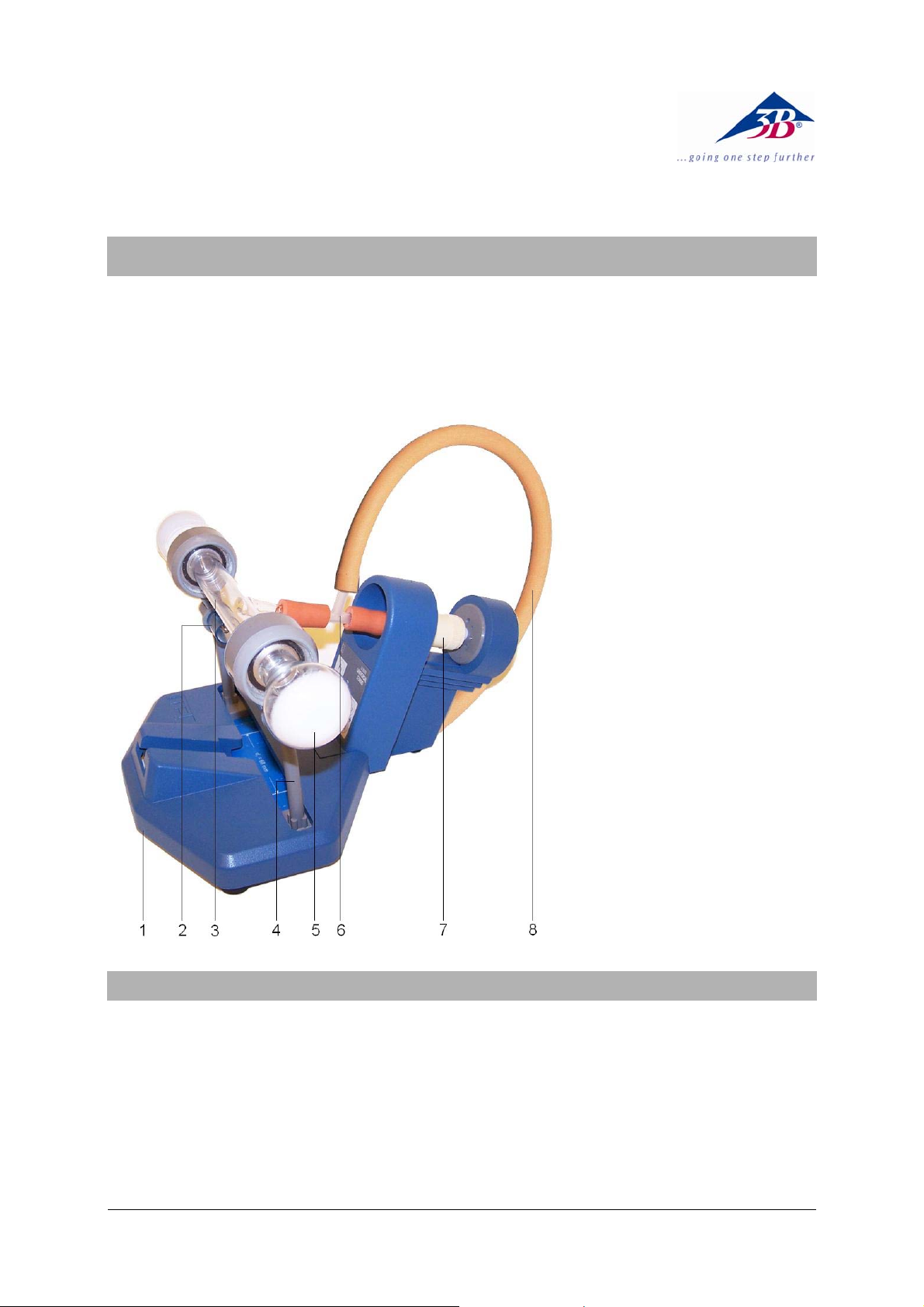
1 Tube holder S (not in-
cluded)
2 4 mm contact pins
3 Glass tube with pump
nozzles
4 Holder
5 End cap with fluorescent
screen
6 T tube connector
7 Vent valve
8 Vacuum hose
1. Safety instructions
Discharge tubes are capable of producing Xrays at operating voltages ≥ 5kV.
• Do not operate the discharge tubes with volt-
ages in excess of 5 kV.
The discharge tube is a thin-walled glass tube. A
damaged tube may implode when evacuated.
• Do not subject the discharge tube to any
mechanical stresses and use it with care.
• Check the tube for damage before using it in
an experiment.
When the discharge tube is in operation, high
voltages may be present at the electrodes.
• Do not attempt any wiring unless the power
supply is switched off.
1
Page 2
2. Description
The gas discharge tube S is used for observation of electrical discharges in gases under reduced pressure as well as for investigation of
cathode beams and canal rays, which appear at
low pressure outside the discharge path.
The gas discharge tube is a glass tube which
can be evacuated and which has luminescent
screens at either end. It is supplied in dismantled form and is intended to be set up on the Sseries tube holder (1014525).
3. Contents
1 Glass tube with pump nozzles
2 End caps with fluorescent screen
2 Holders with sealing washers, electrodes with
slotted apertures and 4-mm terminal pins
1 Vent valve
1 T-connector
3 Vacuum hoses (2x short, 1x long)
4. Technical data
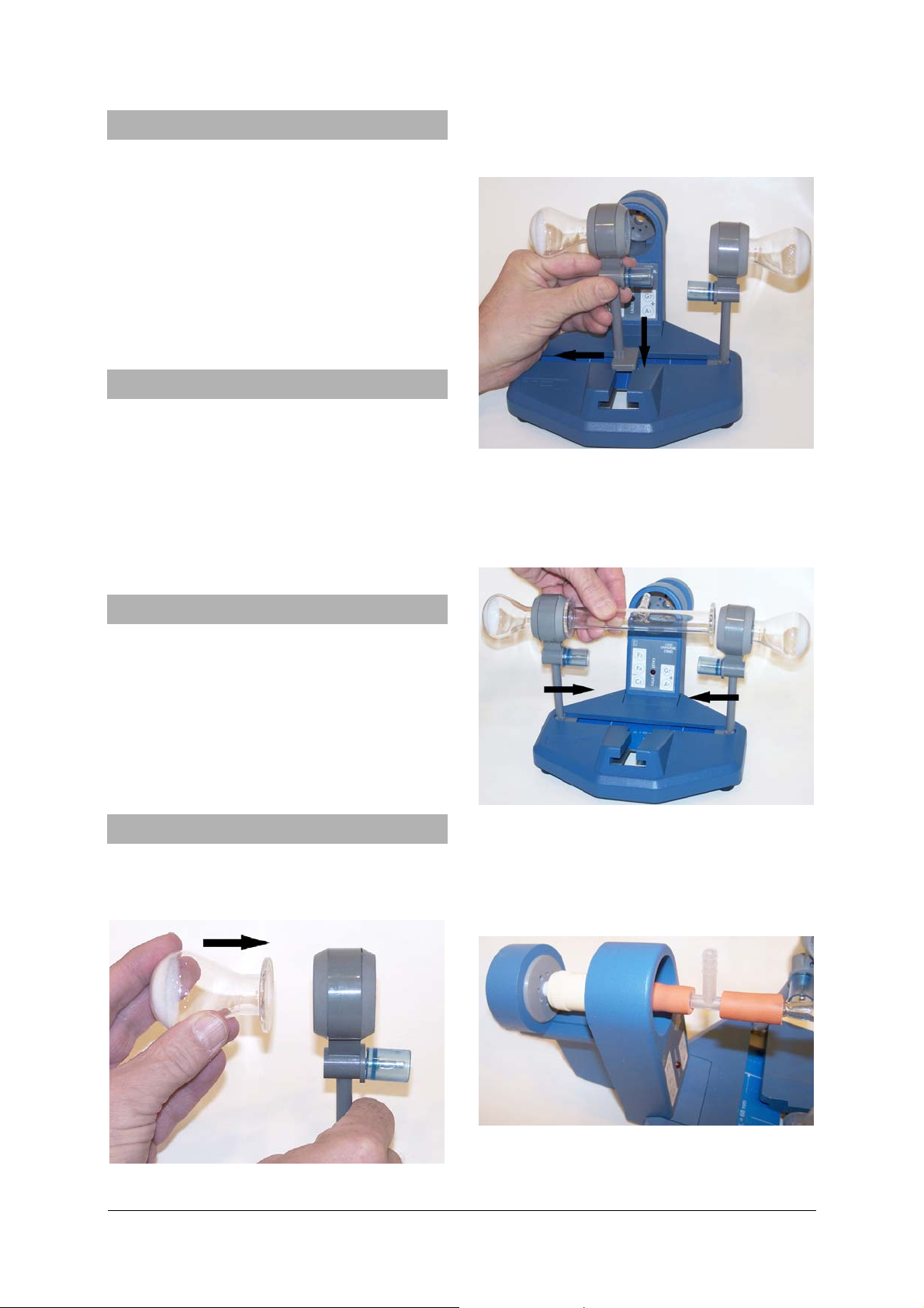
• Slot both holders into the slit in the tube holder
unit and move them all the way to the left or
right (see Fig. 2).
Fig. 2
•
Insert the glass tube into the holders. In order to
ensure that the glass tube is firmly held in place,
push the holders slightly towards the centre
(see Fig. 3).
Polarization voltage: ≤ 5 kV
Discharge current: 1.2 mA approx., de-
pending on gas pres-
sure
Connections: 4 mm contact pins
Tube length: 130 mm x 15 mm diam.
Total length: 280 mm approx.
5. Operation
5.1 Set-up for S-model discharge tube in S-
series tube holder (1014525)
• Fit the end caps into the holder (see Fig. 1).
Fig. 3
• Connect the vent valve to the T-connector using
a short hose and use the second short hose to
connect the connector to the glass tube. Insert
the vent valve into the central hole in the tube
(see Figs. 4 and 5).
holder
Fig. 1
Fig. 4
2
Page 3

5.2 Experiment instructions
To perform experiments using the gas discharge
tube S, the following equipment is also required:
1 Tube holder S 1014525
1 Rotary-vane vacuum pump, two-stage
1003317
2 Experiment lead, safety plug and socket
1002839
1 High voltage power supply, 5 kV (230 V, 50/60 Hz)
1003310
or
1 High voltage power supply, 5 kV (115 V, 50/60 Hz)
1003309
• Connect the hose to the vacuum pump.
• Connect the power supply to the 4-mm ter-
Gas discharges with various gases
• Allow a sequence of different gases into the
tubes.
The luminescent phenomena will differ depending
on the gas used.
• Use a spectroscope to view spectral lines.
Magnetic deflection of anode rays and cathode rays
• At pressures below 10
-2
millibars, move a permanent magnet towards the tube and observe
how it deflects the rays.
Due to the differing masses of the particles involved, the image of the slit on the fluorescent
screen does not move much for the anode rays, but
the cathode rays are deflected heavily
minal pins.
• Apply a voltage of 5 kV to demonstrate lumi-
nescent discharges.
• After the operating voltage is applied, evacuate
the tube and close the vent valve.
• Darken the room and observe the luminescent
phenomena.
• When the experiment is finished, turn off the
pump and open the vent valve to let air into the
discharge tube.
Gas discharge at low pressure
Depending on the range of pressure, various phenomena may be observed when high voltage is
applied:
Pressure range Phenomena
1013 mbar No discharge
30 – 10 mbar
10 – 1 mbar
Threads of light between
cathode and anode
Dark space in front of the
cathode
1 – 10-1 mbar Discharging in layers
10-1 – 10-2 mbar Glowing light
Anode rays and cathode rays,
10-2 mbar
(images of respective slits on
fluorescent screens)
A TELTRON Product from UK3B Scientific Ltd. ▪ Suite 1 Formal House, Oldmixon Crescent ▪ Weston-super-Mare
Somerset BS24 9AY ▪ Tel 0044 (0)1934 425333 ▪ Fax 0044 (0)1934 425334 ▪ e-mail uk3bs@3bscientific.com
Technical amendments are possible
© Copyright 2012 3B Scientific GmbH
Page 4

 Loading...