

Page 1
3B SCIENTIFIC
SW Set - Ultrasonics (230 V, 50/60 Hz) 1012845
SW Set - Ultrasonics (115 V, 50/60 Hz) 1012846
Instruction manual
08/12 TL
®
PHYSICS
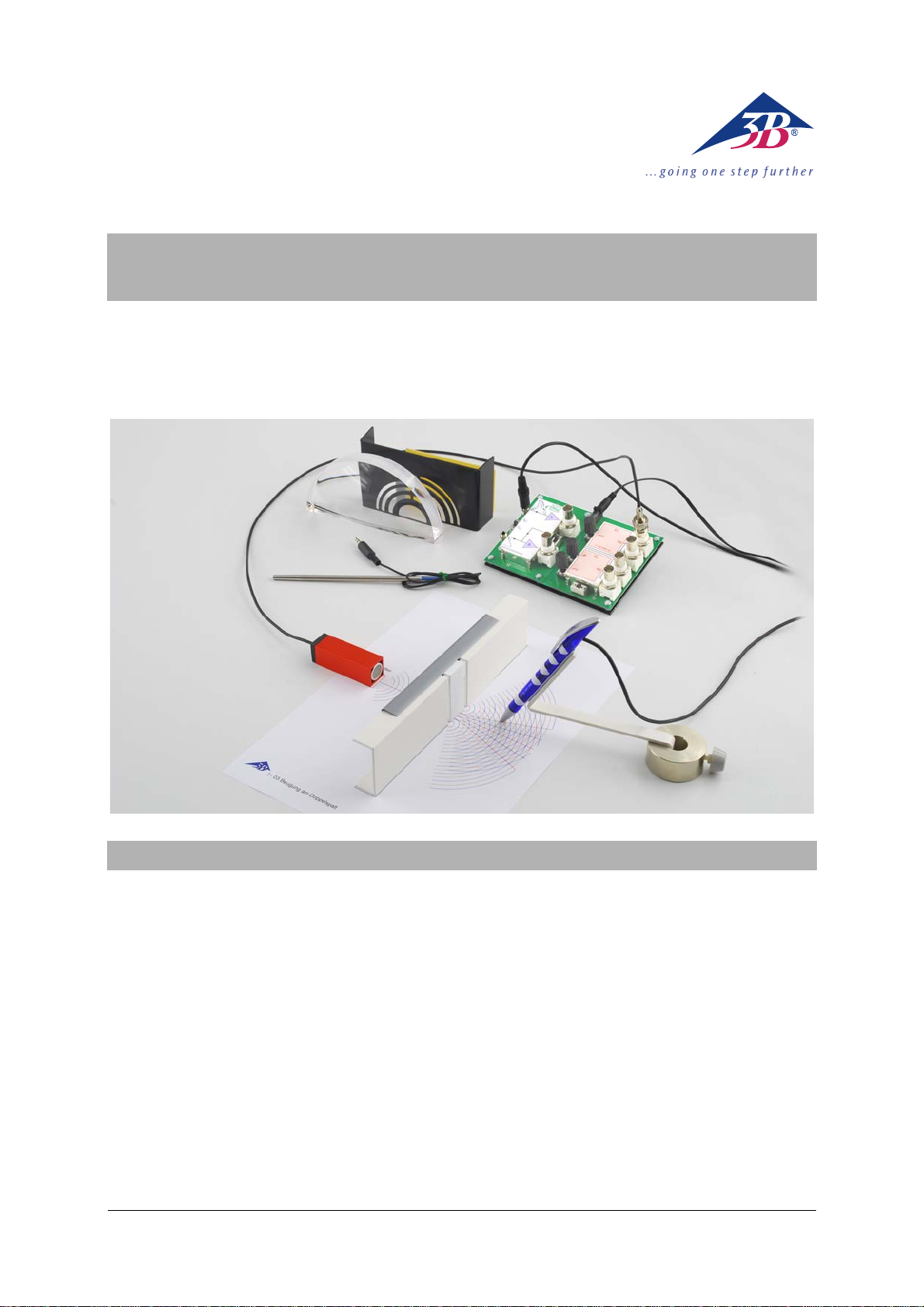
1. Description
The SW set for ultrasonics is designed to demonstrate the fundamental properties of waves in
the form of a space-saving table-top set-up,
using 40-kHz ultrasonic waves as an example.
The sound is propagated along the surface of
the table, to a good approximation. Diffraction
objects, plane and convex mirrors etc. are therefore designed to be set up in the plane above
the table top. This facilitates setting up easily
understood experiments using work templates
and overlays.
Suitable probes make it possible to record oscillations at any point of the wave and to measure
the field of sound after reflection, wave diffraction and interference. One of these probes, the
ultrasonic pen, also features a phase indicator in
the form of an LED, the brightness of which is
reduced to a minimum when the phase difference between the point where the measurement
is being made and a selected reference point is
a multiple of 360°. The ultrasonic pen can thus
be used to record wave fronts as lines of similar
phase, for example (isophases).
For some advanced experiments it is recommended that a multimeter with a suitable frequency response be used to measure the amplitude of ultrasonic waves. Connecting a dualchannel oscilloscope allows the ultrasonic oscillations at the location of the probe to be displayed.
The equipment set with the order no. 1012845 is
designed for mains voltage of 230 V (±10%),
while set no. 1012846 is for 115 V (±10%).
1
Page 2
2. Equipment supplied
1 Holder for ultrasonic pen
2 Ultrasonic pen
3 BNC cable, 1 m (2x)
4 Microphone probes (2x)
5 BNC/4-mm cable
6 Set for double slit
including 2 mirrors/reflectors
7 Electronics board
8 Fresnel zone plate
9 Semi-transparent mirror, 50%
10 Semi-transparent mirror, 25%
11 Ultrasonic absorber
12 Convex mirror
13 Ultrasonic transmitter, 40 kHz (2x)
14 Plug-in power supply (230 V, 50/60 Hz)
or
1 Plug-in power supply (115 V, 50/60 Hz)
not shown
1 Set of templates not shown
3. Electrical safety
The SW ultrasonics set conforms to safety regulations for electrical measurement, control and
laboratory equipment as specified in DIN EN
61010 part 1. It is designed for operation in dry
rooms suitable for electrical equipment.
Safe operation of the system is guaranteed if used
as stipulated. Safety cannot, however, be assured if
the equipment is treated incorrectly or carelessly.
4. CE compliance
The SW ultrasonics set (electronics board, ultrasonic pen and microphone probe) conform to
European guidelines for electromagnetic compatibility (EC 108/2004) and are therefore CE
compliant.
2
Page 3
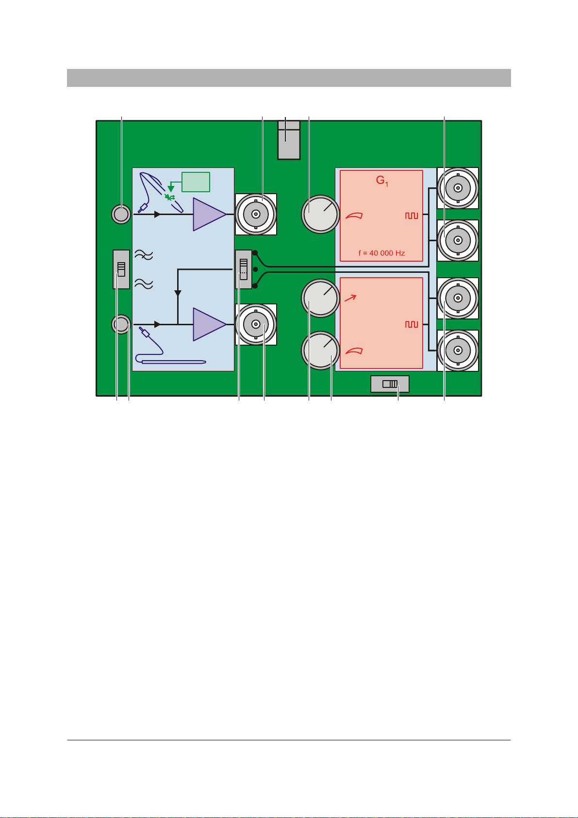
5.1 Electronics board
Δϕ
AB
A
5. Components
12 91013
11
12V AC
G
2
f
B
1 3 5 86 72 4
Fig. 1 Electronics board
1 Switch S1
2 Input for channel B
3 Switch S2
4 Output for channel B
5 Frequency trimmer for generator G2
6 Amplitude trimmer for generator G2
7 Switch S3
8 Outputs for generator G2
9 Outputs for generator G1
10 Amplitude trimmer for generator G1
11 Co-axial connector for plug-in power supply
12 Output for channel A
13 Input for channel A
40 kHz25 kHz
The electronics board for operating the equipment provides the power feed for the ultrasonic
transmitter and amplification for signals from the
microphone probes or ultrasonic pen, as well as
handling control of the phase indicator in the
ultrasonic pen.
The electronics board consists of a generator
block in two parts and a two-channel amplifier
block, which also includes a functional unit for
comparing phase between the two channels.
The AC voltages for the ultrasonic transmitter
are produced in the generator block. Generator
G1 is stabilised to 40.000 kHz by a quartz oscillator, while G2 can be switched between frequencies of 25 and 40 kHz, which can also be
varied by about ±0.5%. Both generators are
equipped with an amplitude trimmer and two
output sockets connected in parallel.
In the amplifier block, the voltages from the ultrasonic probes are amplified and output to the
BNC sockets. It is possible to connect a highpass filter into the circuit for both channels, in
order to filter out low-frequency components of
the sound.
After the input amplifiers there is a functional
block which compares the signals from channels
3
Page 4

A and B and converts the results into a DC current proportional to the phase difference. This
current is then fed via the input socket of channel A to the ultrasonic pen. If the phase difference is a multiple of 360°, the brightness of the
LED on the pen will be reduced to a minimum.
Generator G1:
Frequency: 40.000 kHz,
stabilised by quartz os-
cillator
Amplitude: Adjustable
Output: 2 BNC sockets,
connected in parallel
Generator G2:
Frequency range 1: 38 … 42 kHz approx.
Frequency range 2: 24 … 26 kHz approx.
Frequency ranges: Switchable
Amplitude: Adjustable
Output: 2 BNC sockets,
connected in parallel
Amplifiers (channels A and B):
Input resistance: 10 kΩ
Bias: 8 V
Gain 100 approx.
Output resistance: 1 kΩ
Frequency range: 2 kHz … 43 kHz
(± 3 dB) with high-pass
filter
2 Hz … 43 kHz
(± 3 dB) without high-
pass filter
Inputs: Jack sockets
Outputs: BNC sockets
Phase comparison between A and B:
Control current for
ultrasonic pen: 0 …15 mA (DC)
Coupling with B: Generator signal G1,
Generator signal G2
or off
General data:
Power supply: 12 V AC, 500 mA
from plug-in transformer
Dimensions: 100x140x45 mm approx.
Weight: 530 g approx. including
plug-in power supply
Plug-in power supply for 1012845:
Primary side: 230 V, 50/60 Hz
Secondary side: 12 V AC; 750 mA
Plug-in power supply for 1012846:
Primary side: 115 V, 50/60 Hz
Secondary side: 12 V AC; 500 mA
5.2 Ultrasonic transmitter, 40 kHz
Ultrasonic transmitter for setting up on a table
top with an ultrasonic transducer located flush
with the exit opening inside a square aluminium
tube. Gently curved resonance characteristic for
operation in frequency range 1 of Generator G2
or at a frequency of 40.000 kHz.
Note: Frequency range 2 on the ultrasonic elec-
tronics board can only be output using a separate ultrasonic transducer which is not included
in the SW ultrasonics set.
Input voltage: 20 V AC RMS/
70 Vpp max.
Impedance: > 500 Ω
Acoustic pressure: 110 dB at 10 V
Band width: > 7 kHz/-90 dB
Frequency: 40 kHz (±1 kHz)
Connectors: BNC plugs
Dimensions: 20 x 20 x 60 mm approx.
Cable length: 1 m approx.
5.3 Microphone probe
Warning: The transducer in the microphone
probe is sensitive to moisture and mechanical
effects.
• Do not subject the transducer to any me-
chanical stresses and do not let it come into
contact with liquids.
Microphone probe for setting up on a table top
with transducer positioned flush with the entry
opening in a thin metal tube.
Frequency range: 1 Hz to 43 kHz
Output: Signal for
channel A or B
Connectors: 3.5-mm jack plugs
(tip)
Cable length: 1 m approx.
Dimensions: 6 mm x 150 mm approx.
Weight: 25 g approx.
4
Page 5

5.4 Ultrasonic pen (including holder)
Warning: The transducer in the ultrasonic pen
is sensitive to moisture and mechanical effects.
• Do not subject the transducer to any me-
chanical stresses and do not let it come into
contact with liquids.
Ultrasonic probe with built-in transducer and
additional phase indicator in the form of an LED,
controlled by a current generated by the electronics board from the signal voltages of channels A and B. The brightness of the LED is reduced to a minimum when the phase difference
between the point where the measurement is
being made and a selected reference point is a
multiple of 360°.
The equipment can be held and moved by hand
or, in order to avoid interference from reflections, in the supplied holder.
Phase indicator input
(from channel A only): 0 … 15 mA (DC)
Frequency range: 1 Hz to 43 kHz
Output: Signal for
channel A or B
Connectors: 3.5-mm jack plugs,
input: ring
output: tip
Cable length: 1 m approx.
Dimensions: 10 mm x 150 mm approx.
Weight: 32 g approx. without
holder
5.5 Convex mirror
Transparent plastic convex mirror designed for
the space above a table top.
Focal length: 100 mm
Radius of curvature: 200 mm
Dimensions: 140 x 20 x 70 mm approx.
5.6 Fresnel zone plate
Plastic Fresnel zone plate designed for the
space above a table top.
Focal length: 35 mm
Dimensions: 140 x 20 x 50 mm approx.
5.7 Ultrasonic absorber
Component for demonstrating sound insulation
or for suppressing sound travelling directly from
transmitter to microphone probe in some experiments.
Surface: Fleece textile
Dimensions: 80 x 15 x 50 mm approx.
5.8 Set for double slit
Set of equipment for setting up a double or single slit or for use as individual reflectors or mirrors.
Surface: Plastic coated
Dimensions: 100 x 20 x 50 mm approx.
or
20 x 20 x 50 mm approx.
5.9 Semi-transparent mirror (50%) and
Semi-transparent mirror (25%)
Partially transparent and partially reflecting mirrors made of perforated plastic (50%) or expanded aluminium (25%).
Dimensions: 100 x 20 x 60 mm approx.
5.10 BNC cable
For connecting amplifier outputs to an oscilloscope.
Cable length: 1 m approx.
5.11 BNC/4-mm cable
For connecting amplifier outputs to an analog
voltmeter.
Cable length: 1 m approx.
5.12 Set of work templates
Work templates for experiments:
• Diffraction at an edge
• Propagation of waves beyond a slit
• Diffraction by a double slit
• Constructive und destructive interference
arising from diffraction by a double slit
• Lloyd’s mirror
• Set-up for a simple interferometer
• Set-up for a Michelson interferometer
5
Page 6

6. Operation
6.1 Ultrasonics experiments at 40.000 kHz
Fig. 2 Measurement of ultrasonic amplitude using a
multimeter
Required:
1 Electronics board with plug-in power supply
1 Ultrasonic transmitter, 40 kHz
1 Microphone probe
or
1 Ultrasonic pen
1 BNC cable
or
1 BNC/4-mm cable
Additionally required:
1 USB oscilloscope, 2x40 MHz 1012845
or
1 Analog oscilloscope, 2x20 MHz 1008695
or
1 ESCOLA 10 multimeter 1006810
• Connect the supplied plug-in transformer to
provide power to the equipment.
• Turn on the high-pass filter by means of
switch S1 (
• Connect the 40-kHz ultrasonic transmitter to
) and set switch S2 to .
the output of Generator G1.
• Place the microphone probe opposite the
transmitter and connect it to channel A or B
on the electronics board.
Note: The ultrasonic pen can be used instead of the microphone probe and connected to channel A or B. Its tip should point
towards the sound source.
• Connect the output of the channel to an
oscilloscope (measuring ranges 1 V/div, 2
µs/div) or a multimeter (measuring range:
AC, 10 V).
• Observe the amplitudes of the oscillations
with the oscilloscope or via the deflection of
the multimeter and vary the amplitude of the
ultrasound from the transmitter using the
amplitude trimmer.
Note: the deflection of the multimeter needle
is initially proportional to the set amplitude.
At higher amplitudes the amplifier becomes
overdriven and the output voltage takes on a
square-wave character, since the voltage
level at Output A merely switches between
the negative and positive operating voltages
of the electronics board. The oscilloscope
displays a trapezoidal or square curve.
6.2 Ultrasonic experiments with variable
frequencies
Required:
1 Electronics board and plug-in power supply
1 Ultrasonic transmitter, 40 kHz
1 Microphone probe
or
1 Ultrasonic pen
1 BNC cable
Additionally required:
1 USB oscilloscope, 2x40 MHz 1012845
or
1 Analog oscilloscope, 2x20 MHz 1008695
• Connect the supplied plug-in transformer to
provide power to the equipment.
• Turn on the high-pass filter by means of
switch S1 (
• Connect the 40-kHz ultrasonic transmitter to
) and set switch S2 to .
the output of Generator G2.
• Place the microphone probe opposite the
transmitter and connect it to channel A or B
on the electronics board.
Note: The ultrasonic pen can be used instead of the microphone probe and connected to channel A or B. Its tip should point
towards the sound source.
• Connect the output of the channel to an
oscilloscope (measuring ranges 1 V/div, 2
µs/div).
• Observe the amplitudes of the oscillations
with the oscilloscope and vary the amplitude
of the ultrasound from the transmitter using
the amplitude trimmer.
• Observe the period of oscillation with the
oscilloscope and vary the frequency of the
transmitter using the frequency trimmer.
6
Page 7

6.3 Investigation of phase differences using the phase indicator on the ultrasonic pen
Required:
1 Electronics board and plug-in power supply
1 Ultrasonic transmitter, 40 kHz
1 Ultrasonic pen
2 BNC cables
Additionally required:
1 USB oscilloscope, 2x40 MHz 1012845
or
1 Analog oscilloscope, 2x20 MHz 1008695
• Connect the supplied plug-in transformer to
provide power to the equipment.
• Connect the ultrasonic transmitter to Gen-
erator G1 or alternatively to Generator G2.
• Connect the ultrasonic pen to channel A.
• Turn on the high-pass filter by means of
switch S1 (
in order to couple to Generator G1 or
) and either set switch S2 to
in
order to couple to Generator G2.
• Connect the channel outputs to the oscillo-
scope..
• Move the ultrasonic pen to a position where
the LED acting as a phase indicator is lit to
its maximum intensity and compare the
phase differences between the two signals.
Note: the phase indicator shows the difference between the generator signal and the
signal received from the ultrasonic pen.
The phase relationship between two arbitrary points on the ultrasonic wave are analysed when a microphone probe is connected to channel A and switch S2 is set to
.
6.4 Recording of isophases or determination of wavelength with the ultrasonic
pen
Fig. 3 Positioning of ultrasonic pen on work base and
alignment towards sound source
Required:
1 Electronics board and plug-in power supply
1 Ultrasonic transmitter, 40 kHz
1 Ultrasonic pen
1 Holder for ultrasonic pen
• Use a plain sheet of paper as a base.
• Connect the supplied plug-in transformer to
provide power to the equipment.
• Connect the ultrasonic transmitter to Gen-
erator G, for example.
• Connect the ultrasonic pen to channel A and
set it up in its holder in such a way that the
tip is only about 1 mm from the paper with
the holder pointing towards the sound
source.
• Turn on the high-pass filter by means of
switch S1 (
) and set switch S2 to in or-
der to couple to Generator G1.
• Move the ultrasonic pen to a position where
the LED is only lit to its minimum intensity.
• Use a fine pen to mark the position of the
ultrasonic pen’s tip on the paper.
To record isophases:
• Move the ultrasonic pen across the line of
the beam until the phase indicator is once
again at its minimum, making sure you keep
the pen pointing towards the transmitter.
• Use a fine pen to mark the new position of
the ultrasonic pen on the paper.
To determine wavelength:
• Move the ultrasonic pen in the direction of
the beam until the phase indicator is once
again at a minimum.
• Use a fine pen to mark the new position of
the ultrasonic pen on the paper.
7
Page 8

7. Experiments
7.1 Lloyd’s mirror
Fig. 4 Reflection from Lloyd’s mirror
Required:
1 Electronics board and plug-in power supply
1 Ultrasonic transmitter, 40 kHz
1 Microphone probe
1 Reflector
1 BNC/4-mm cable
Additionally required:
1 ESCOLA 10 multimeter 1006810
• Connect the supplied plug-in transformer to
provide power to the equipment.
• Connect the ultrasonic transmitter to Gen-
erator G1.
• Connect the microphone probe to channel A
and set it up some distance in front of the
transmitter.
• Connect the output of the channel to the
multimeter (measuring range: AC, 10 V).
• Turn on the high-pass filter by means of
switch S1 (
• Set up the reflector parallel to the main
) and set switch S2 to .
beam.
• Change the distance of the reflector from the
main beam and observe the maxima and
minima in the measured sound amplitude.
Note: If the distance between the plane between
the transmitter and receiver and reflecting surfaces such as the base plate is equal to certain
specific values, then the direct beam and the
one reflected from the surface may be superimposed in such a way that destructive interference ensues. With Lloyd’s mirror it is possible to
determine the minimum distance at which this
effect occurs. The effect does not occur at all if
the transmitter and receiver are set up so close
together on the base plate that they are nearer
to each other than this minimum distance.
7.2 Reflection from a convex mirror
Fig. 5 Reflection of a diverging sound beam by a
convex mirror
Required:
1 Electronics board and plug-in power supply
1 Ultrasonic transmitter, 40 kHz
1 Ultrasonic pen with holder
or
1 Microphone probe
1 Convex mirror
1 Absorber
1 BNC/4-mm cable
Additionally required:
1 ESCOLA 10 multimeter 1006810
• Connect the supplied plug-in transformer to
provide power to the equipment.
• Connect the ultrasonic transmitter to Gen-
erator G1.
• Connect the ultrasonic pen, or alternatively a
microphone probe, to channel A and set it
up some distance in front of the transmitter.
• Connect the output of the channel to the
multimeter (measuring range: AC, 10 V).
• Turn on the high-pass filter by means of
switch S1 (
• Set up the convex mirror and point the
) and set switch S2 to .
transmitter towards it.
• Set up the reflector parallel to the direct
beam.
• Find the optimum position for the receiver by
using a geometric construction and position
the ultrasonic pen at that point.
• Move the ultrasonic pen until the received
signal is at a maximum.
Note: The alignment of the receiver and transmitter with the convex mirror is comparable to a
domestic satellite dish.
8
Page 9

7.3 Diffraction by an edge
Fig. 6 Recording isophases when plane waves are
diffracted by an edge
Required:
1 Electronics board and plug-in power supply
1 Ultrasonic transmitter, 40 kHz
1 Ultrasonic pen with holder
1 Convex mirror
1 Reflector
• Connect the supplied plug-in transformer to
provide power to the equipment.
• Set up the convex mirror and mark the focal
point (focal length 100 mm).
• Connect the ultrasonic transmitter to Gen-
erator G1 and set it up facing the convex
mirror at the mirror’s focal point.
• Turn on the high-pass filter by means of
switch S1 (
) and set switch S2 to in or-
der to couple to Generator G1.
• Connect the ultrasonic pen to channel A and
set it up in its holder in such a way that the
tip is only about 1 mm from the template.
• Set up the ultrasonic pen in its holder behind
the transmitter such that it is pointing towards the convex mirror.
• Move the ultrasonic pen until the phase indi-
cator goes out and then mark the position of
the ultrasonic pen on the template.
• To record the wave fronts after reflection
from the convex mirror move the ultrasonic
pen across the axis of the beam and mark
the points where the brightness of the phase
indicator is art a minimum.
• Move the ultrasonic pen in the direction of
the beam and record the following isophase.
• Set up the reflector such that diffraction oc-
curs at its edge and determine the altered
isophases due to the diffraction.
Note: The isophases (points where the brightness is at a minimum) correspond to a “snapshot” of the wave fronts. The distance between
two isophases is equal to one wavelength.
7.4 Diffraction by a double slit
Fig. 7 Diffraction by a double slit
Note: New circular wave fronts emerge from
both slits. The template already has such wave
fronts drawn on it with a separation of half a
wavelength. The points where these lines cross
form lines (hyperbolae) indicating constructive
and destructive interference.
Required:
1 Electronics board and plug-in power supply
1 Ultrasonic transmitter, 40 kHz
1 Ultrasonic pen with holder
1 Set for double slit
1 Absorber
1 BNC/4-mm cable
Additionally required:
1 ESCOLA 10 multimeter 1006810
• Connect the supplied plug-in transformer to
provide power to the equipment.
• Use the appropriate template.
• Set up the double slit, making sure the slits
are the same width (about 5 mm).
• Connect the 40-kHz ultrasonic transmitter to
Generator G1 and align it with the middle of
the double slit.
• Turn on the high-pass filter by means of
switch S1 (
) and set switch S2 to in or-
der to couple to Generator G1.
9
Page 10

•
Connect the ultrasonic pen to channel A and
set it up in its holder in such a way that the
tip is only about 1 mm from the template.
• Place the ultrasonic pen in its holder behind
the double slit on one of the pre-drawn wave
fronts.
• Move the ultrasonic transmitter in the direc-
tion of the beam till the phase indicator goes
out.
• Confirm the locations of the wave fronts are
as drawn on the template by moving the ultrasonic pen appropriately.
• Position the ultrasonic pen at a point on one
of the blue hyperbolae, carefully align it towards the middle of the double slit and identify by the minimal needle deflection on the
multimeter that this is a diffraction minimum.
• Move the ultrasonic pen parallel to the dou-
ble slit and look for diffraction minima and
maxima.
Note: If the ultrasonic pen is at the position of
one of the first diffraction minima, covering one
or other of the slits should cause the intensity at
the measuring point to increase markedly. In
addition, it is possible to demonstrate with the
help of an oscilloscope that the measured
curves from the two slits have the same amplitude but are phase-shifted by 180°.
8. Disposal
Should the equipment need
to be scrapped, it must not
be disposed of in normal
household waste.
• Packaging and compo-
nents should be disposed of at local recycling centres.
3B Scientific GmbH ▪ Rudorffweg 8 ▪ 21031 Hamburg ▪ Germany ▪ www.3bscientific.com
Subject to technical amendments
© Copyright 2012 3B Scientific GmbH
 Loading...