

Page 1
3B SCIENTIFIC
SW Set – String Pendulum 1012854
Instruction manual
09/13 TL/ALF
®
PHYSICS
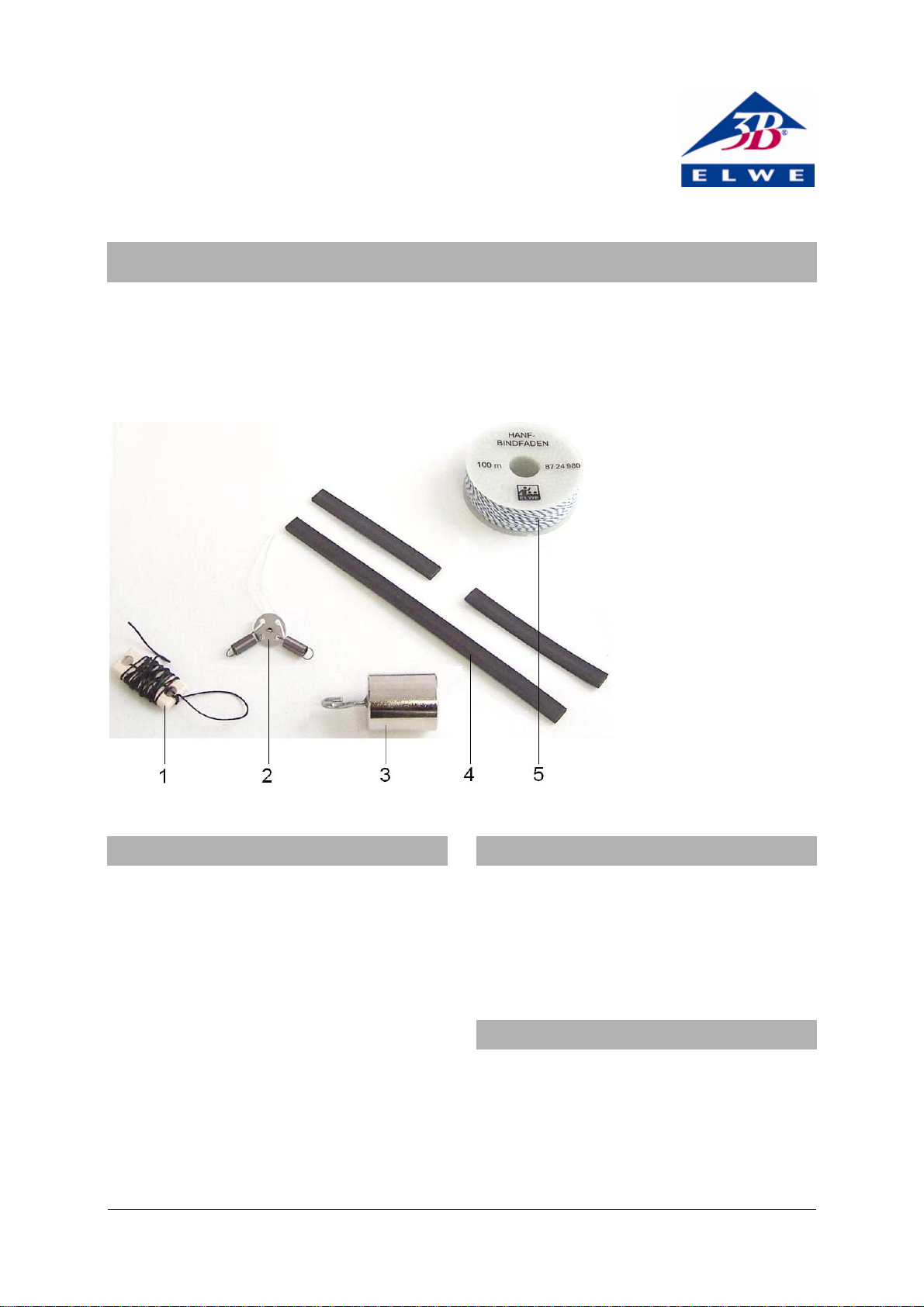
1 String with length adjust-
ment slider
2 Spring module with vector
plate
3 Weight
4 Set of magnetic strips
5 Roll of string
1. Description
The SW string pendulum set has everything you
need to build a string pendulum and carry out
extensive experiments on harmonic and chaotic
oscillations using a space-saving table-top setup.
It features a roll of string, a weight, a movable
plastic slider for changing the length of the pendulum and magnetic strips for the purpose of
creating chaotic oscillations. A spring module
makes it possible to connect the pendulum to
the dynamic force sensors from the SW sensors
set in order to record and analyse oscillations
with two degrees of freedom by means of an
oscilloscope.
2. Equipment
1 String, 100 m
1 Weight 100 g
1 Long magnetic strip
2 Short magnetic strips
1 Spring module
3. Technical data
Spring constant of
individual springs: 80 N/m approx.
Maximum force permitted
on pendulum string: 10 N
Maximum recommended
deflection of pendulum: 25°
1
Page 2
4. Functioning principle
In a stationary position, the only forces acting on
the hook of the dynamometer are those of the
opposing tension springs (cf. Fig. 2). All motion
of the string pendulum about the effectively stable eyelet hole from which it is suspended is
resolved into two vectors and detected by the
dynamic force sensors. For small angles, the
output voltage from the amplifier board is almost
proportional to the deflection of the pendulum
(cf. Fig. 5).
A circular motion of the pendulum creates sinusoidal AC voltages at both amplifier outputs,
which are out of phase with one another by 90°or
-90° depending on the direction of rotation.
5. Operation
5.1 General information
The following additional equipment is necessary
in order to carry out the experiments:
1 SW stand equipment set 1012849
1 SW sensors set (@230V) 1012850
or
1 SW sensors set (@115V) 1012851
1 USB oscilloscope 2x 50 MHz 1017264
1 PC, operating system Win XP, Vista, Win 7
or
1 Analogue oscilloscope 2x 30 MHz 1002727
Caution: Dynamic force sensors must not be
subjected to mechanical overloading
• Neither sensor hook may be loaded with
more than 5N in the axial direction and 1 N
in transverse direction.
• Be especially careful with the maximum load-
ing force when assembling the system or
suspending loops or springs from the hook.
• Make sure stand rods are firmly fitted into
the base and that all other mounting elements are also firmly fitted to the stands.
5.2 Set-up for string pendulum
• Screw the stand rods with both external and
internal threads into the outer threaded
sockets of the base plate.
• Extend both rods by screwing rods with ex-
ternal thread only onto the ends of them.
• Attach double clamps near the top of both
stand rods and turn them to point inwards so
that the slots are vertical and facing one another.
• Attach both springs from the spring module
to the lugs on the cross bar (angled side).
• Hang the large loop of string from the lug on
the flat side.
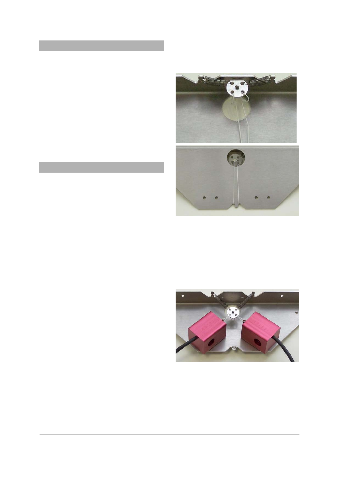
Fig. 1 Assembly of spring module
• Connect the springs and vector plate to the
hook of a dynamic force sensor with a small
loop of string and carefully pull everything
taut.
• Attach the force sensor with the screw tight-
ened by hand.
• Attach the second force sensor in the same
way.
Fig. 2 Attachment of dynamic force sensors to spring
module
• Pull the string through the eyelet of the spring
module (in the middle of the metal disc).
• Thread the end of the string through the two
holes of the length adjustment slider.
2
Page 3

Fig. 3 Set up of string
• Clamp the cross bar into the slots of the two
double clamps, suspend a weight from the
end of the string and set up the height of the
pendulum using the length adjustment
slider.
Fig. 4 Attachment of cross bar in double clamp
• Connect the force sensors to the inputs for
channels A and B of the MEC amplifier
board.
• Connect the outputs to an oscilloscope and
start the experiment.
5.3. Set up for chaotic pendulum
• Set up the pendulum as previously de-
scribed.
• In order to make the pendulum chaotic,
place magnetic strips on the base plate under the pendulum bob.
6. Disposal
• Packaging and compo-
nents should be disposed of, where necessary, at local recycling
centres.
Fig. 5 Measured voltage as a function of pendulum deflection
3
Page 4

Fig. 6 String pendulum with USB oscilloscope
3B Scientific GmbH ▪ Rudorffweg 8 ▪ 21031 Hamburg ▪ Germany ▪ www.3bscientific.com
Subject to technical amendments
© Copyright 2013 3B Scientific GmbH
 Loading...