

Page 1
3B SCIENTIFIC® PHYSICS
Basic solar energy set 1000839
Instruction sheet
03/12 ALF
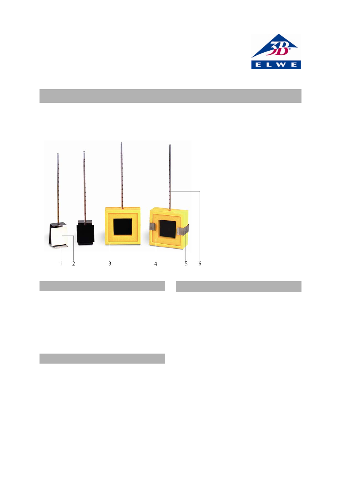
1 Holder for metering panel
2 Solar metering panel
3 Insulating case
4 Acrylic plate
5 Clamp
6 Thermometer
1. Safety instructions
The metering panels and halogen lights get hot during the experiments so that there is a risk of burns.
• Let the sample panels and halogen lights cool
down when the experiment is finished.
The thermometers are sensitive instruments, made
from glass. Caution, they are fragile!
• Do not expose to mechanical stress.
2. Description
The basic solar energy set is an equipment set for
experiments on utilisation of solar energy.
The equipment set consists of four sample solar
metering panels, with which it is possible to make
four simultaneous measurements during an experiment lasting about 25 minutes. Comparing the four
sets of measurements allows conclusions to be
drawn about the change in temperature and the
maximum temperature that can be reached by the
sample panels, which all differ in terms of surface
coating, heat insulation and covering.
3. Contents / Technical data
4 Solar metering panels
Material: Copper
Dimensions: 60 x 60 mm
2
Colour: 1 white, 3 black
Weight: 50 g approx.
2 Insulating cases
Material: Foam
Dimensions: 1 120 x 120 x 50 mm
1 Acrylic plate 100 x 100 mm
2
4 Thermometers -10° C – +100° C
2 Holders for metering panels
2 Clamps
1 Storage box
3
1
Page 2
4. Experimental set-up
T
If the experiment cannot be conducted in direct
sunlight, a 500 W halogen lamp has to be used as a
substitute.
Recommended accessories:
1 Halogen lamp, 500 W (230 V, 50/60 Hz) 1000894
or
1 Halogen lamp, 500 W (115 V, 50/60 Hz) 1000893
1 Tripod stand 1002835
• Position one black and one white sample panel
in each of the holders and place the other two
black panels in an insulating case. The smooth,
coloured side should point towards the light
source.
• Put the thermometer through the drill hole in
the holder or the insulating case, respectively,
and into the bottom hole at the rear of the metering panel.
• Mount the acrylic plate with the clamps to one
of the insulating cases.
• Position the metering panels at the same dis-
tance and angle to the light source.
5. Experimental protocol
• Position the halogen lamp at a distance of ap-
proximately 30 to 40 cm from the metering panels.
• Read thermometer before the experiment, and
take a note of the reading.
• Switch on lamp.
• Read the temperature every minute, enter it into
a table and plot a graph of the results.
The various metering panels reach their maximum
temperature within different periods of time.
The covered metering panel reaches its maximum
temperature after approximately 25 min.
The experiment can be halted once the maximum
temperature has been reached.
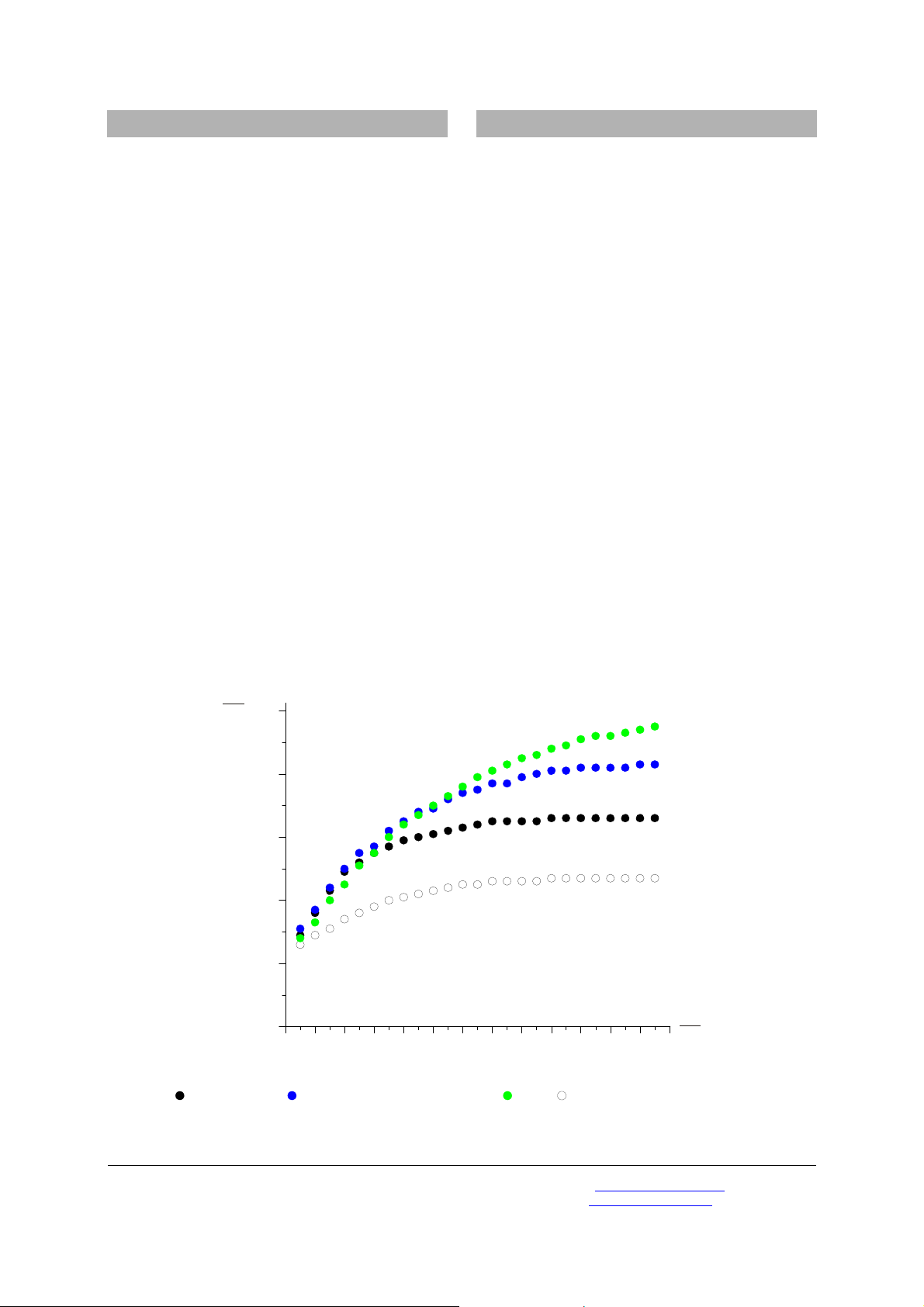
It can easily be seen (Fig. 1) that black surfaces lead
to a much higher rate of temperature increase than
white ones.
The thermal insulation of the insulating case prevents energy losses from the rear of the metering
panel. Adding the acrylic plate improves utilisation
of the radiant power, since the “greenhouse effect”
prevents cooling of the meter panel by atmospheric
convection and by long-wave heat dissipation from
the front. This “greenhouse effect” even compensates
for the losses due to absorption by the acrylic plate,
which are reflected in the slightly shallower initial
slope of the measured curve. The black metering
panel, furnished with thermal insulation and a
cover, has all the physical attributes of a solar collector panel for a hot water heater.
100
° C
80
60
40
20
0
Fig. 1 Temperature increase in the solar meter panels
Black (
),black, insulated ( ),black, insulated, with acrylic plate ( ),white ( )
0 2 4 6 8 10 12 14 16 18 20 22 24 26
min
t
Elwe Didactic GmbH • Steinfelsstr. 5 • 08248 Klingenthal • Germany • www.elwedidactic.com
3B Scientific GmbH • Rudorffweg 8 • 21031 Hamburg • Germany • www.3bscientific.com
Subject to technical amendments
© Copyright 2012 3B Scientific GmbH
 Loading...