

Page 1
3B SCIENTIFIC
Sine Wave Generator U8533550
Instruction Sheet
01/08 SP/ALF
®
PHYSICS
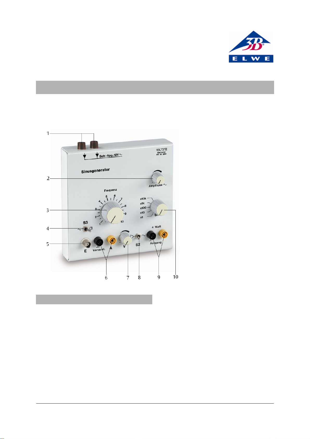
1 Supply voltage input
2 Amplitude control
3 Frequency control
4 Microphone/amplifier selector
switch (S3)
5 Amplifier input
6 Pre-amplifier output
7 Amplification control
8 Generator/preamplifier
selector switch (S2)
9 Power amplifier output
10 Frequency range selector
switch (S1)
1. Safety instructions
The sine wave generator conforms to safety
regulations for electrical measuring, control and
laboratory equipment as specified in DIN EN 61010
Part 1 and is designed to meet protection
classification I. It is to be operated in dry rooms as
appropriate for the use of electrical equipment.
Safe operation of this equipment is guaranteed as
long as it is used as stipulated. However, there is no
guarantee of safety if the equipment is used
incorrectly or carelessly. If there is any suspicion that
the equipment can no longer be operated without
risk (e.g. if visible damage is detected), the equipment
must immediately be withdrawn from use and
secured in such a way as to prevent its inadvertent
operation.
In schools and other educational institutions, the
instrument must only be used under the supervision
of a responsible person.
• Before operating the sine wave generator it needs
to be examined and tested. If it fails to function
correctly or if there is visible damage it must
immediately be withdrawn from use and secured
in such a way as to prevent its inadvertent
operation.
• Only use the instrument in a dry environment.
• Do not apply any external voltage to the output
terminals.
• Do not allow the instrument to be opened by
anyone other than an electrically qualified
specialist.
1
Page 2
2. Description
The sine wave generator is used to generate
sinusoidal voltages in a frequency range from 1Hz to
100kHz. A selector switch allows the instrument to be
Input: AC coupled, microphone
Max. output voltage: 10 Vpp
Max. output current: 15 mA, short-circuit
used either as a sine wave generator with power
output or as a power amplifier with a pre-amplifier
stage.
The frequency can be selected over a range of 5
decades, each of which is continuously adjustable on
a scale from 1 to 10. The power amplifier has a robust
output stage and a large reserve of power. The output
stage is thermally protected and proof against shortcircuiting, and the output is current-limited.
With the mode selector switch (S3) in the microphone
position
, the socket marked E is supplied with +8V
Output impedance: 1 kΩ
Power amplifier:
Voltage amplification: 0 - 8.5
Operating voltage: 12 V AC
Dimensions: 160×160×50 mm
Weight: 1.1 kg approx.
via a 10kΩ resistor. This bias voltage is suitable for
direct connection to an electret microphone or
carbon microphone.
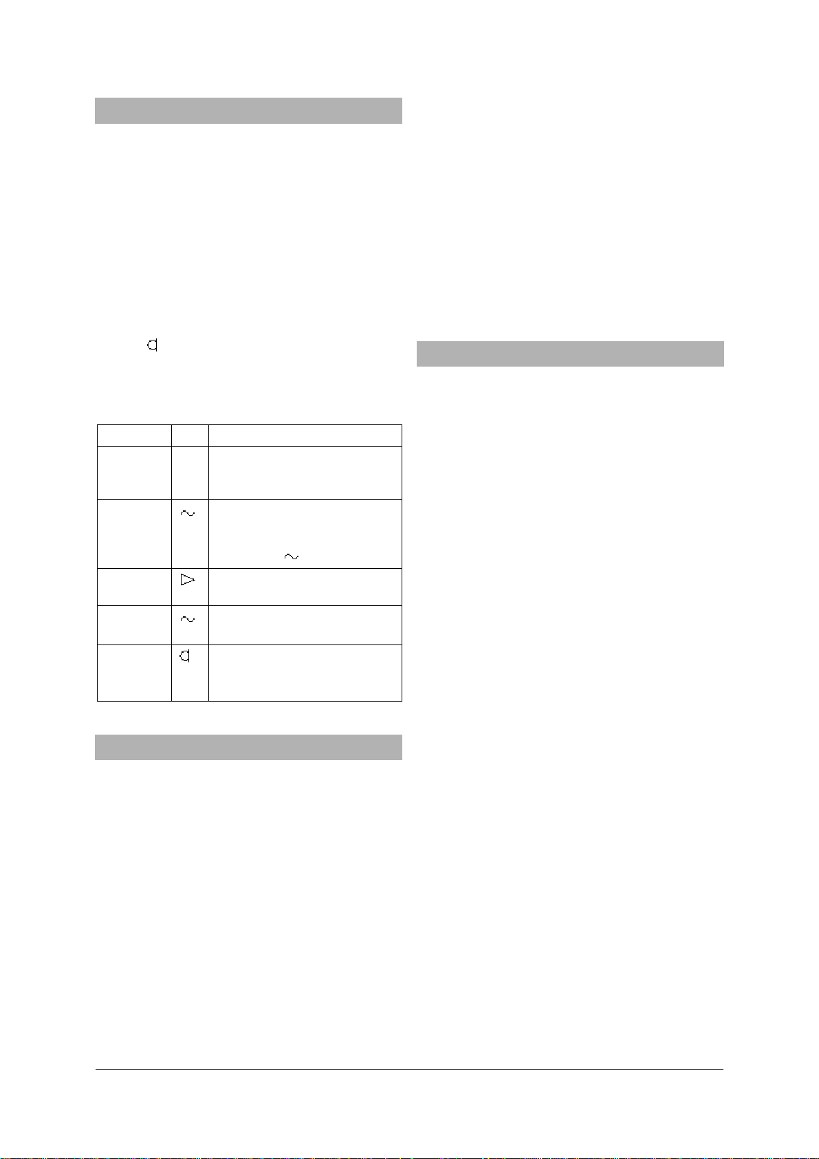
Modes of operation:
Switch Function
S1 Frequency decade switch (acts
as multiplier to the “Frequency”
adjustment)
S2
Sinusoidal voltage available at
power amplifier output –
output adjustable via
“Amplitude
Pre-amplifier output is fed to
“ knob
power amplifier output stage
S3
Input to preamplifier through
100 μF capacitor
Bias voltage (8 V, 10 kΩ); input
to preamplifier through 1 μF
capacitor
3. Technical data
Sine wave generator with power output
Frequency range: 1 Hz - 100 kHz in 5
decades, continuously
adjustable by linear
marked dial
Frequency deviation: < 5%
Recommended voltage supply source:
Transformer, 12 V, 25 VA U8475430-230
or
Transformer, 12 V, 25 VA U8475430-115
The output stage is very robust and can be relied on
to work safely in physics experiments. However, when
working with inductive loads (coils, transformers,
motors, etc.) the following precautions need to be
taken:
Switching onto an inductive load may only be done
when there is no signal (i.e., with the “Amplitude”
and/or “V” control knobs fully to the left).
Speakers can be damaged if the equipment is
switched on when there is already a signal voltage.
Therefore, before switching on, set the signal level to
zero (amplification control knob “V” fully to the left).
When the unit is operating at a high power level the
housing can become hot. Although the output stage is
not likely to be damaged by heat, under such
conditions a longer cooling period should be allowed
for.
To avoid excessive heating when operating
continuously for a long period, it is advisable to keep
the load resistance above 3Ω.
• Connect the mains adapter transformer to the
4.1 Operation as a power amplifier with pre-
Output voltage: 0 - 6 V, adjustable
Max. output current: 10 A, short-circuit
• Set switch S3 (4) to either the microphone
protected
Max. output power: 16 W continuous, 30 W for
short periods
Input resistance: 100 kΩ
Pre-amplifier
• Turn the amplification control knob (7) fully to
• Connect the pair of output sockets (9) to the load
Amplification factor: 1- 250, continuously
adjustable
voltage switch
protected
3
approx.
4. Operation
supply voltage input terminals.
amplifier stage
position (right) or the amplifier position (left) as
required, and switch S2 (8) to the pre-amplifier
position (left).
the left (zero).
(e.g., low frequency speaker U8432780, horn
speaker U8432680, etc.).
2
Page 3

•
Increase the amplitude using the amplification
control (7) (do not exceed the maximum
permitted power for the equipment that is
connected).
4.2 Operation as a sine wave generator with power
output
• Set switch S2 (8) to the generator position (right).
• Turn the amplitude control knob (2) fully to the
left.
• Connect the pair of output sockets (9) to the load
(e.g., low frequency loudspeaker U8432780, horn
loudspeaker U8432680, vibration generator
U56001, 12V DC motor U8552330, etc.).
• Increase the amplitude using the amplitude
control (2) (do not exceed the maximum
permitted power for the equipment that is
connected).
Elwe Didactic GmbH • Steinfelsstr. 6 • 08248 Klingenthal • Germany • www.elwedidactic.com
3B Scientific GmbH • Rudorffweg 8 • 21031 Hamburg • Germany • www.3bscientific.com
Subject to technical amendment
© Copyright 2008 3B Scientific GmbH
Page 4

 Loading...