

Page 1
3B SCIENTIFIC® PHYSICS
U20600 Kundt’sche Röhre
U20601 Mikrofonsonde
U20602 Batteriekasten
Bedienungsanleitung
11/02 ALF
®
Der Gerätesatz Kundt’sche Röhre und Zubehör dient zur
Darstellung stehender Schallwellen mit offenen oder geschlossenen Rohrenden sowie zur Bestimmung der Wellenlängen in Luft oder anderen Gasen.
1. Sicherheitshinweise
• Mikrofon und Lautsprecher vor Feuchtigkeit schützen.
• Fremdspannung an der Anschlussleitung des Mikro-
fons max. 5V .
• Acrylglaskörper nicht mit aggressiven Reinigern oder
Lösungsmitteln säubern.
2. Beschreibung, technische Daten
2.1 Kundt’sche Röhre
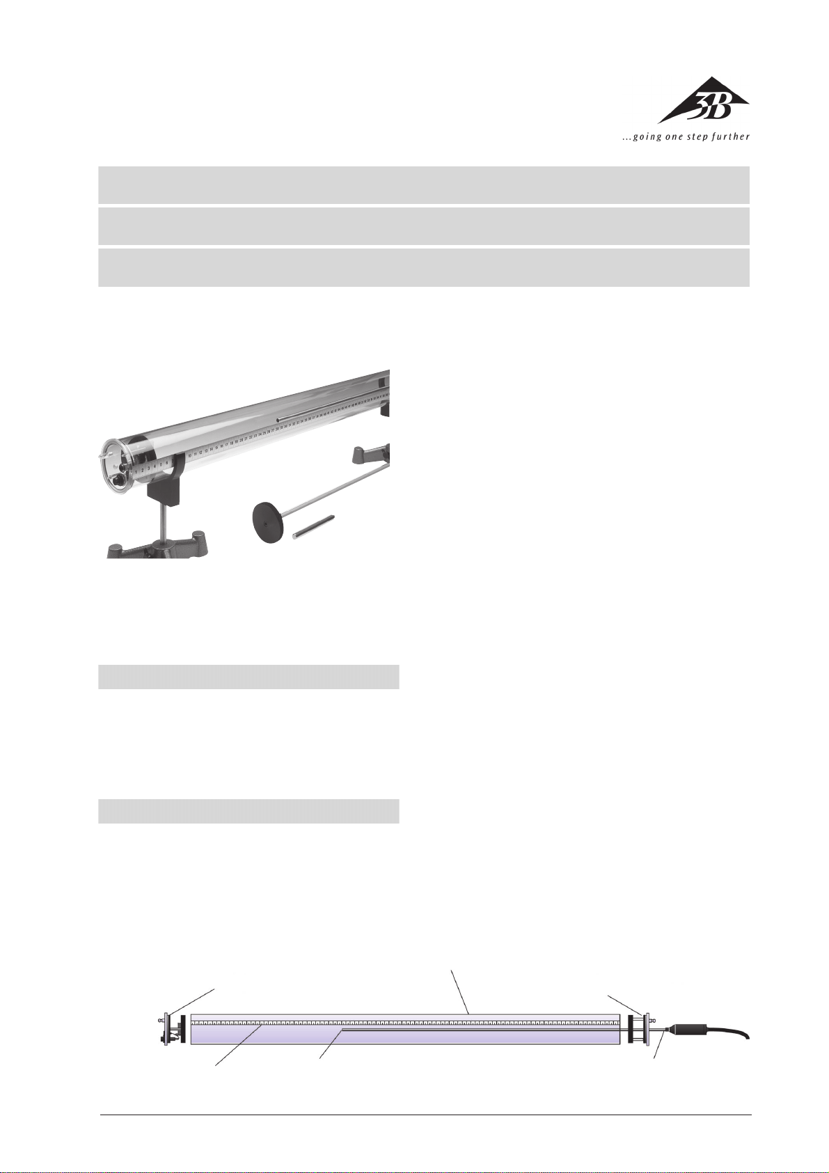
Der Gerätesatz Kundt’sche Röhre besteht aus einer
Acrylglasröhre mit Skala und zwei abnehmbaren Endplatten mit eingebauten Schlaucholiven zum Befüllen
des Rohres mit verschiedenen Gasen. An einem Ende
ist ein Lautsprecher eingebaut, am anderen Ende befin-
1
det sich eine Bohrung mit Führung zur Aufnahme des
beweglichen Stempels oder der Mikrofonsonde
(U20601).
Zwei Halteklammern zur Aufnahme der Kundt’schen
Röhre in Stativmaterial sowie Anschlusskabel für Lautsprecher vervollständigen den Gerätesatz.
Länge: 1000 mm
Durchmesser: 70 mm
Schlaucholive: 7 mm Ø
Maßstab: 1000 mm
Teilung: mm und cm
Abbildung:
1 Endplatte mit Lautsprecher, 4-mm-Buchsen und
Schlaucholive
2 Resonanzröhre
3 Endplatte mit Bohrung und Führung zur Aufnahme
des Stempels oder der Mikrofonsonde
4 Mikrofonsonde
5 Mikrofon
6 Skala
2
3
6
5
4
1
Page 2
2.2 Mikrofonsonde
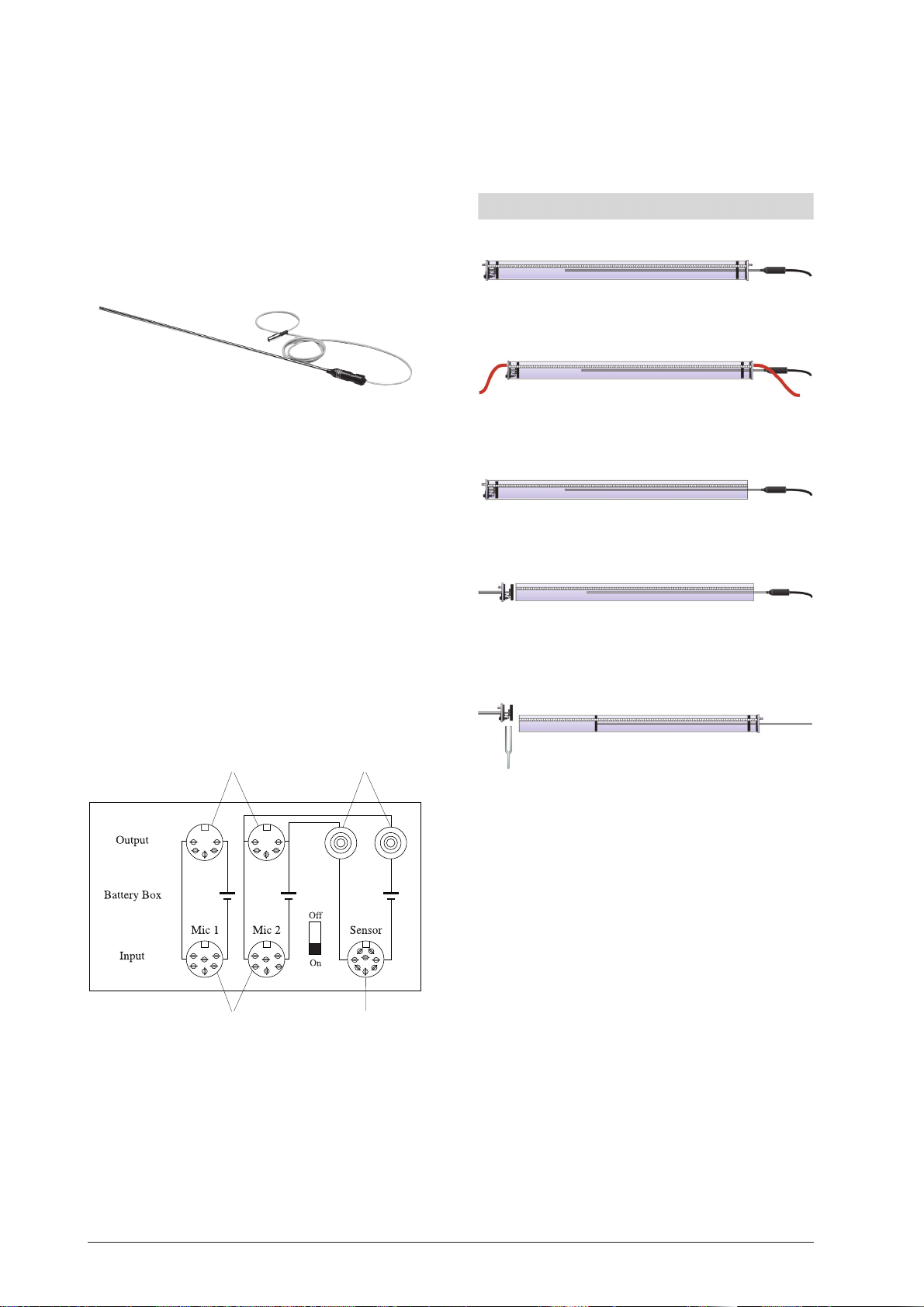
Die Mikrofonsonde dient zur Messung von Schalldruckveränderungen in der Kundt’schen Röhre.
Ein Miniaturmikrofon ist am Ende eines langen Stabs aus
rostfreiem Stahl befestigt. Es wird mit einem 5-poligenDIN-Stecker mit dem Batteriekasten (U20602) verbunden.
Der Batteriekasten bietet die Anschlussmöglichkeit eines
Oszilloskops oder eines Voltmeters. Über den Adapter
U20603 kann die Mikrofonsonde direkt an den Digitalzähler (U21000) angeschlossen werden.
Hinweis: Bei gleichzeitiger Verwendung der Mikrofonsonde U20601 und eines Oszilloskops Mikrofonsonde am
Eingang Sensor (3) und Oszilloskop am Ausgang (2) anschließen.
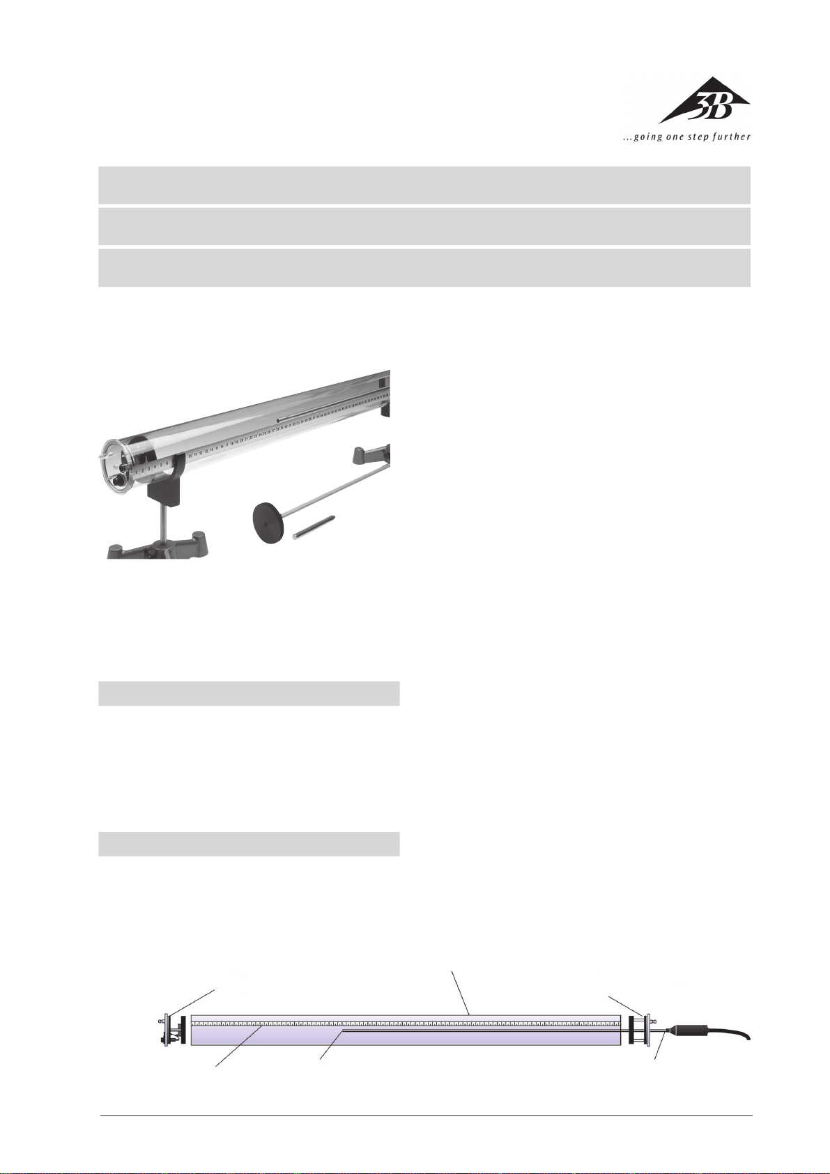
3. Versuchsbeispiele
3.1 Stehende Wellen in einer geschlossenen Röhre
3.2 Stehende Wellen in Kohlendioxyd
Frequenzbereich des Mikrofons: 20 Hz bis 20000 Hz
Abmessungen der Sonde: 740 mm x 8 mm Ø
Länge des Anschlusskabels: 2 m
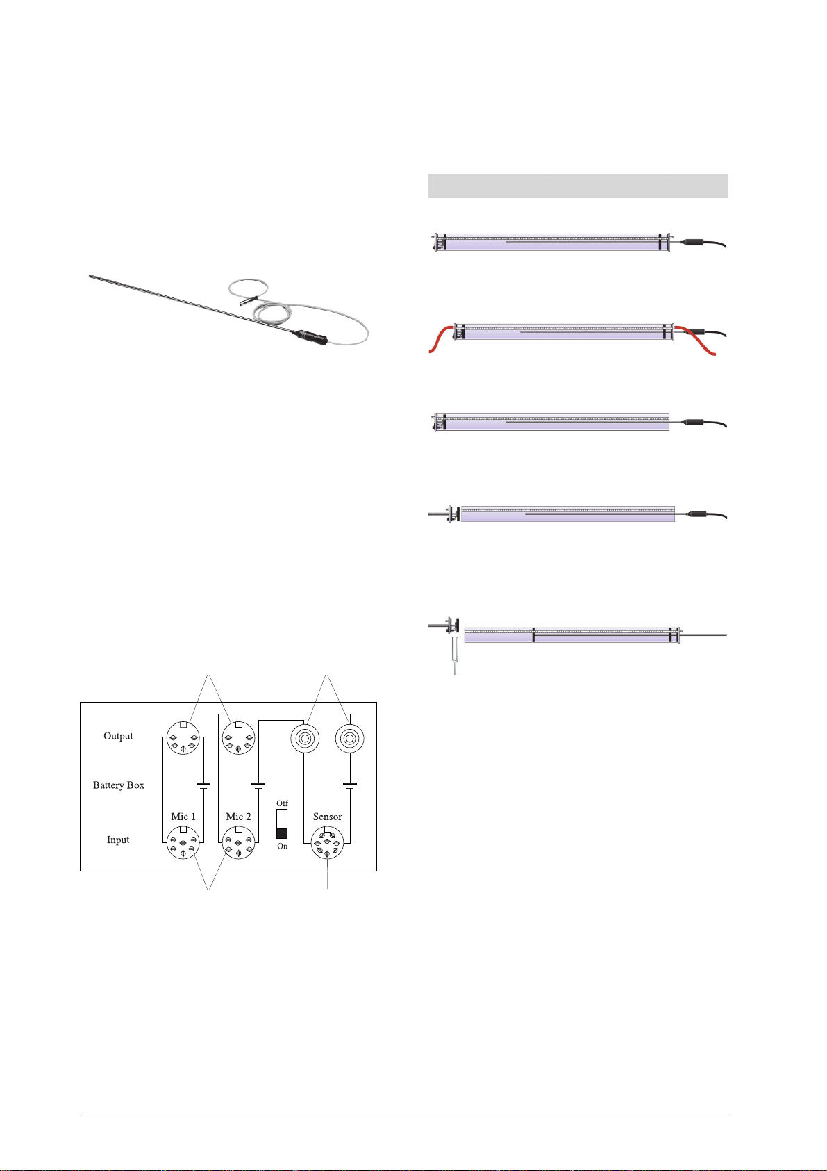
2.3 Batteriekasten
Der Batteriekasten dient zur Stromversorgung von Mikrofonen (z.B. U20601 oder U18030) und anderen analogen Sensoren mit einer Versorgungsspannung von 5 V
DC, um sie direkt an ein Messgerät oder ein Oszilloskop
anzuschließen.
Das Gerät verfügt über ein Batteriefach für eine 9 V AlkaliBatterie, die über einen Regler die benötigte 5 V DC liefert. Als Eingangskanäle stehen zwei 6-polige DIN-Buchsen (180°) sowie eine 8-polige DIN-Buchse (270°) zur Verfügung. Zum Anschluss von Messgeräten dienen zwei 5polige DIN-Buchsen und zwei 4-mm-Sicherheitsbuchsen.
Abmessungen: 143 mm x 84 mm x 37 mm
1
2
3.3 Stehende Wellen in einer Röhre mit einem
offenen Ende
3.4 Stehende Wellen in einer offenen Röhre
3.5 Veränderung der Luftsäule
Schallquelle: Stimmgabel oder Lautsprecher
Zusätzlich erforderlich zur Durchführung der Versuche
sind ein Funktionsgenerator (z.B. U21015) zur Anregung
des Lautsprechers und ein Oszilloskop (z.B. U11175) zur
Darstellung der Schwingungsknoten und -bäuche.
3.6 Bestimmung der Schallgeschwindigkeit in Luft
• Aufbau der Kundt’schen Röhre in Stativmaterial mit
geschlossenen Enden und der Mikrofonsonde sowie
Anschluss eines Funktionsgenerators (z.B. U21015)
und eines Oszilloskops (z.B. U11175).
• Anlegen einer Frequenz f von 2700 Hz an den Laut-
4
3
1 DIN-Buchsen zum Anschluss von Messgeräten
2 4-mm-Sicherheitsbuchsen zum Anschluss eines Os-
zilloskops, eines Voltmeters oder eines Interfaces
3 DIN-Buchse zum Anschluss verschiederner Sensoren
oder Ausgang für LabPro Interface über Adapter
4 DIN-Buchsen zum Anschluss von Mikrofonen
3B Scientific GmbH • Rudorffweg 8 • 21031 Hamburg • Deutschland • www.3bscientific.com • Technische Änderungen vorbehalten
2
sprecher .
• Mit der Mikrofonsonde die Knotenpunkte abfahren
und die Entfernung mittels des Maßstabs bestimmen.
• Man erhält einen mittleren Abstand benachbarter
Knoten von ca. 6,3 cm.
• Daraus ergibt sich die Wellenlänge λ = 12,6 cm.
• Die Schallgeschwindigkeit lässt sich mittels der For-
mel c = f · λ berechnen.
c = 2,7 · 103 · 12,6 · 10–2 m/s = 340 m/s
Page 3
3B SCIENTIFIC® PHYSICS
U20600 Kundt’s tube
U20601 Microphone probe
U20602 Battery box
Operating instructions
11/02 ALF
®
The equipment set comprising Kundt’s tube and
accessories is meant to display stationary sound waves
with open or closed tube ends and determine
wavelengths in air and other gases.
1. Safety instructions
• Protect the microphone and loudspeaker against
moisture.
• The external voltage through the microphone’s
connection line should not exceed 5V .
• Do not clean the acrylic glass body with aggressive
agents or solvents.
2. Description, technical data
The equipment set designated Kundt’s tube consists of
an acrylic-glass tube with a scale, two removable end
plates and an integrated hose nipple for filling the tube
with various gases. One end plate is furnished with a
loudspeaker, the other with a bore and guide for
1
mounting a movable piston or microphone probe
(U20601).
The equipment set includes two clamps for mounting
Kundt’s tube on a tripod, and cables for connecting the
loudspeaker.
Length: 1000 mm
Diameter: 70 mm
Hose nipple: 7 mm Ø
Scale: 1000 mm
Division: mm and cm
Drawing:
1 End plate with loudspeaker, 4-mm jacks and hose
nipple
2 Resonance tube
3 End plate with bore and guide for mounting a piston
or microphone probe
4 Microphone probe
5 Microphone
6 Scale
2
3
6
5
4
3
Page 4
2.2. Microphone probe
The microphone probe is used to measure changes in
sound pressure inside Kundt’s tube.
A miniature microphone is attached to the end of a long
rod made of stainless steel. It is connected by means of
a 5-pole DIN plug to the battery box (U20602). This battery
box also has a terminal for connecting an oscilloscope or
voltmeter. The microphone probe can be connected
directly to the digital counter (U21000) via the adapter
U20603.
Microphone’s frequency range: 20 Hz to 20000 Hz
Probe’s dimensions: 740 mm x 8 mm Ø
Connection cable’s length: 2 m
2.3. Battery box
The battery box supplies the microphones (for instance,
U20601 or U18030) and other analog sensors with a power of 5 V DC so that they can be connected directly with
a measuring device or an oscilloscope.
The box consists of a compartment for a 9-V alkaline
battery which supplies the required 5 V DC via a regulator.
Two 6-pole DIN jacks (180°) and one 8-pole DIN jack (270°)
are available as input channels. Two 5-pole DIN jacks and
two 4-mm safety jacks serve for connecting measuring
devices.
Dimensions: 143 mm x 84 mm x 37 mm
Note:In order to make simultaneous use of the microphone probe U20601 and an oscilloscope, connect the
microphone probe to the sensor input (3) and the oscilloscope to the output (2).
3. Sample experiments
3.1 Stationary waves in a closed tube
3.2 Stationary waves in carbon dioxide
3.3 Stationary waves in a tube with one closed end
3. Stationary waves in an open tube
3.5 Changes in the air column
Sound source: Tuning fork or loudspeaker
1
4
2
3
1 DIN jacks for connecting measuring devices
2 4-mm safety jacks for connecting an oscilloscope,
voltmeter or interface
3 DIN jack for connecting various sensors or a LabPro
interface via an output adapter
4 DIN jacks for connecting microphones
To perform these experiments, additional use is required of a function generator (for example, U21015)
to excite the loudspeaker , and an oscilloscope (for
instance, U11175) to display the oscillation nodes
and antinodes.
3.6 Determination of the speed of sound in air
• Install Kundt’s tube with closed ends and the microphone probe on a tripod; connect a function
generator (for instance, U21015) and an oscilloscope
(for instance, U11175).
• Apply a frequency f = 2700 Hz to the loudspeaker.
• Move the microphone probe past the nodes and
measure the intervals between them using the scale.
• The average interval between two neighbouring
nodes turns out to be 6.3 cm.
• This results in a wavelength λ = 12.6 cm.
• The speed of sound c is calculated with the for-
mula c = f ·
c = 2,7 · 103 · 12,6 · 10–2 m/s = 340 m/s
λ
3B Scientific GmbH • Rudorffweg 8 • 21031 Hamburg • Germany • www.3bscientific.com • Technical amendments are possible
4
Page 5

3B SCIENTIFIC® PHYSICS
U20600 Tube de Kundt
U20601 Sonde de microphone
U20602 Boîtier à pile
Instructions d’utilisation
11/02 ALF
®
Le jeu d’appareils constitué du tube de Kundt et de ses
accessoires permet d’illustrer les ondes acoustiques stationnaires avec des extrémités de tube ouvertes ou fermées ainsi que de déterminer la longueur d’onde dans
l’air ou dans d’autres gaz.
1. Consignes de sécurité
• Protéger le microphone et le haut-parleur contre l’humidité.
• Tension externe de max. 5 V sur le câble de raccord du
microphone.
• Ne pas nettoyer le corps en verre acrylique avec des
nettoyants agressifs ou des solvants.
2. Description, caractéristiques techniques
2.1 Tube de Kundt
Le jeu d’appareils « tube de Kundt » comprend un tube
en verre acrylique avec graduation et deux plaques finales amovibles à olives intégrées pour le remplissage du
tube avec différents gaz. Un haut-parleur est incorporé à
1
une extrémité ; de l’autre se trouve une perforation avec
un guidage pour recevoir le piston mobile ou la sonde
du microphone (U20600).
Deux fixations pour loger le tube de Kundt dans un trépied ainsi qu’un câble de raccord pour le haut-parleur
complètent le jeu.
Longueur : 1 000 mm
Diamètre : 70 mm
Olive : Ø 7 mm
Echelle : 1 000 mm
Pas : mm et cm
Image :
1 Plaque finale avec haut-parleur, douilles de 4 mm et
olive
2 Tube de résonance
3 Plaque finale avec perforation et guidage pour le lo-
gement du piston ou de la sonde du microphone
4 Sonde de microphone
5 Microphone
6 Graduation
2
3
6
5
4
5
Page 6

2.2 Sonde de microphone
La sonde du microphone permet de mesurer les variations de la pression acoustique dans le tube de Kundt.
Un microphone miniature est fixé à l’extrémité d’une
longue tige en acier inoxydable. Il est relié au boîtier à
pile (U20602) à l’aide d’un connecteur DIN à 5 pôles. Ce
boîtier à pile permet le branchement d’un oscilloscope
ou d’un voltmètre. L’adaptateur U20603 permet de relier
directement la sonde du microphone au compteur numérique (U21000).
Gamme de fréquence du micro : 20 Hz à 20 000 Hz
Dimensions de la sonde : 740 mm x Ø 8 mm
Longueur du câble de raccord : 2 m
2.3 Boîtier à pile
Le boîtier à pile permet d’alimenter des microphones
(par ex. U18030 ou U20601) et d’autres capteurs analogiques avec une tension de 5 V CC, permettant ainsi une
connexion directe à un instrument de mesure ou à un
oscilloscope.
L’appareil dispose d’un compartiment pour une pile alcaline 9 V qui fournit les 5 V CC requis via un régulateur .
Deux douilles DIN à 6 pôles (180°) et une à 8 pôles (270°)
sont disponibles comme canaux d’entrée. Deux douilles
DIN à 5 pôles et deux douilles de sécurité de 4 mm permettent la connexion d’instruments de mesure.
Dimensions : 143 mm x 84 mm x 37 mm
Remarque :
Si la sonde de microphone U20601 est utilisée en même
temps qu’un oscilloscope, raccorder la sonde à l’entrée
du capteur (3) et l’oscilloscope à la sortie (2).
3. Exemples d’expériences
3.1 Ondes stationnaires dans un tube fermé
3.2 Ondes stationnaires en dioxyde de carbone
3.3 Ondes stationnaires dans un tube avec une
extrémité ouverte
3.4 Ondes stationnaires dans un tube ouvert
3.5 Modification de la colonne d’air
Source acoustique : diapason ou haut-parleur
1
4
2
3
1 Douilles DIN pour la connexion d’instruments de me-
sure
2 Douilles de sécurité de 4 mm pour la connexion d’un
oscilloscope, d’un voltmètre ou d’une interface
3 Douille DIN pour la connexion de différents capteurs
ou la sortie pour l’interface LabPro via un adaptateur
4 Douilles DIN pour la connexion de microphones
La réalisation des expériences nécessite en outre un générateur de fonctions (par ex. U21015) pour exciter le hautparleur et un oscilloscope (par ex. U11175) pour représenter les nœuds et les ventres d’oscillation.
3.6 Déterminer la vitesse du son dans l’air
• Montage du tube de Kundt dans un trépied avec
extrémités fermées et de la sonde du microphone
ainsi que connexion d’un générateur de fonctions
(par ex. U21015) et d’un oscilloscope (par ex. U11175).
• Application d’une fréquence f de 2 700 Hz sur le
haut-parleur .
• Avec la sonde du microphone, explorer les nœuds
et déterminer la distance à l’aide de la tige.
• On obtient une distance moyenne des nœuds voisins d’env. 6,3 cm.
• Il en résulte la longueur d’onde λ = 12,6 cm.
• La vitesse du son peut être calculée à l’aide de la
formule c = f · λ .
c = 2,7 · 103 · 12,6 · 10–2 m/s = 340 m/s
3B Scientific GmbH • Rudorffweg 8 • 21031 Hamburg • Allemagne • ww w .3 bscientific.com • Sous réserve de modifications techniques
6
Page 7

3B SCIENTIFIC® PHYSICS
U20600 Tubo di Kundt
U20601 Sonda microfono
U20602 Alloggiamento batteria
Istruzioni d’uso
11/02 ALF
®
Il kit per il tubo di Kundt unitamente agli accessori serve
per la dimostrazione delle onde sonore stazionarie con
estremità aperte o chiuse del tubo , e per la determinazione delle lunghezze d’onda nell’aria o in altri gas.
1. Istruzioni di sicurezza
• Proteggere il microfono e l’altoparlante dall’umidità.
• La tensione esterna sulla linea di allacciamento del
microfono non deve superare i 5V .
• Non pulire i corpi in vetro acrilico con detergenti aggressivi o solventi.
2. Descrizione, caratteristiche tecniche
2.1 Tubo di Kundt
Il kit per il tubo di Kundt è costituito da un tubo in vetro
acrilico con scala e due piastre terminali rimovibili con
nippli per tubi incorporati per riempire il tubo con gas
diversi. Su un’estremità è incorporato un altoparlante,
1
sull’altra sono presenti un foro e una guida per accogliere il pistone mobile oppure la sonda microfono (U20601).
Il kit comprende infine due morsetti di supporto per
accogliere il tubo di Kundt nello stativo e un cavo di
collegamento per l’altoparlante.
Lunghezza: 1000 mm
Diametro: 70 mm
Nipplo per tubo: 7 mm Ø
Scala: 1000 mm
Divisione: mm e cm
Figura:
1 piastra terminale con altoparlante, prese da 4 mm e
nipplo per tubi
2 tubo di risonanza
3 piastra terminale con foro e guida per accogliere il
pistone oppure la sonda microfono
4 sonda microfono
5 microfono
6 scala
2
3
6
5
4
7
Page 8

2.2 Sonda microfono
La sonda microfono serve per misurare le alterazioni della
pressione acustica nel tubo di Kundt.
Un microfono miniaturizzato è fissato ad un’estremità di
una lunga asta di acciaio inox. È collegato
all’alloggiamento batteria (U20602) con un connettore
DIN a 5 poli. L’alloggiamento batteria offre la possibilità
di collegare un oscilloscopio oppure un voltmetro . Tramite l’adattatore U20603 la sonda microfono può essere
collegata direttamente al contatore digitale (U21000).
Frequenza del microfono: da 20 Hz a 20000 Hz
Dimensioni della sonda: 740 mm x 8 mm Ø
Lunghezza del cavo
di collegamento: 2 m
2.3 Alloggiamento batteria
L’alloggiamento batteria serve per fornire corrente ai
microfoni (ad es. U20601 o U18030) e ad altri sensori analogici con una tensione di alimentazione di 5 V DC, e per
collegarli direttamente ad un apparecchio di misura o ad
un oscilloscopio.
L’apparecchio dispone di uno scomparto per una batteria alcalina da 9 V, che fornisce la corr ente necessaria da 5
V DC tramite un regolatore. I canali d’ingresso sono costituiti da due prese DIN da 6 poli (180°) e da una presa DIN
da 8 poli (270°). Il collegamento di apparecchi di misura è
realizzato grazie a due prese DIN a 5 poli e due jack di
sicurezza da 4 mm.
Dimensioni: 143 mm x 84 mm x 37 mm
Nota: Se si utilizzano contemporaneamente la sonda microfono U20601 e un oscilloscopio, collegare la sonda
microfono al sensore di ingresso (3)
e l’oscilloscopio all’uscita (2).
3. Esempi di esperimenti
3.1 Onde stazionarie in un tubo chiuso
3.2 Onde stazionarie in anidride carbonica
3.3 Onde stazionarie in un tubo con un’estremità
aperta
3.4 Onde stazionarie in un tubo aperto
3.5 Variazione della colonna d’aria
Sorgente sonora: diapason o altoparlante
1
4
2
3
1 Prese DIN per il collegamento di apparecchi di misura
2 Jack di sicurezza da 4 mm per il collegamento di un
oscilloscopio, un voltmetro o un’interfaccia
3 Presa DIN per il collegamento di diversi sensori o per
l’uscita di LabPro Interface tramite adattatore
4 Prese DIN per il collegamento di microfoni
Per eseguire gli esperimenti sono inoltre necessari un
generatore di funzione (ad es. U21015) per l’eccitazione
dell’altoparlante e un oscilloscopio (ad es. U11175) per la
dimostrazione dei nodi di oscillazione e degli antinodi.
3.6 Determinazione della velocità del suono
nell’aria
• Montaggio del tubo di Kundt nello stativo con estremità chiuse e della sonda microfono, nonché collegamento di un generatore di funzione (ad es. U21015)
e di un oscilloscopio (ad es. U11175).
• Applicazione di una frequenza f di 2700 Hz all’alto-
parlante.
• Con la sonda microfono rilevare i punti nodali e
determinare la distanza tramite la scala.
• Si ottiene una distanza media dei nodi vicini di circa
6,3 cm.
• Da ciò risulta la lunghezza d’onda λ = 12,6 cm.
• La velocità del suono può essere calcolata tramite
la formula c = f · λ .
c = 2,7 · 103 · 12,6 · 10–2 m/s = 340 m/s
3B Scientific GmbH • Rudorffweg 8 • 21031 Hamburg • Germania • www. 3bscientific.com • Con riserva di modifiche tecniche
8
Page 9

3B SCIENTIFIC® PHYSICS
U20600 Tubo de Kundt
U20601 Sonda de micrófono
U20602 Caja de pilas
Instrucciones de uso
11/02 ALF
®
El equipo Tubo de Kundt y accesorios sirve para la representación de ondas sonoras estacionarias con los extremos del tubo abiertos o cerrados, así como para determinar longitudes de onda en el aire o en otros gases.
1. Aviso de seguridad
• El micrófono y el altavoz se deben proteger de la
humedad.
• Tensión externa al cable de conexión del micrófono ,
máx. 5 V.
• El cuerpo de cristal acrílico no se debe limpiar con
elementos corrosivos ni con disolventes.
2. Descripción, datos técnicos
1.1 Tubo de Kundt
El equipo Tubo de Kundt costa de un tubo de vidrio
acrílico, con escala y dos placas terminales removibles,
con boquilla para manguera, para llenar el tubo con diferentes gases. En un extremo se ha incorporado un altavoz, y en el otro se encuentra una perforación con guía
1
para el alojamiento del émbolo móvil o de la sonda de
micrófono (U20601).
Dos sujetadores para el alojamiento del tubo de Kundt
en el material de soporte, así como el cable de conexión
para el altavoz completan el equipo .
Longitud: 1000 mm
Diámetro: 70 mm
Boquilla para manguera: 7 mm Ø
Escala: 1000 mm
División: mm y cm
Figura:
1 Placa terminal con altavoz, clavijero de 4 mm y
boquilla para manguera
2 Tubos de resonancia
3 Placa terminal con perforación y guía para alojamiento
del émbolo o de la sonda de micrófono
4 Sonda de micrófono
5 Micrófono
6 Escala
2
3
6
5
4
9
Page 10

2.2 Sonda de micrófono
La sonda de micrófono sirve para la medición de las
variaciones de presión acústica en el tubo de Kundt.
Se ha fijado un micrófono en miniatura en el extremo de
una larga varilla de acero inoxidable. La conexión a la caja
de pilas (U20602) se realiza por medio de un conector
DIN de 5 polos. La caja de pilas brinda la posibilidad de
conectar un osciloscopio o un voltímetro. La sonda de
micrófono se puede conectar al contador digital (U21000)
por medio del adaptador U20603.
Rango de frecuencia del micrófono: 20 Hz a 20000 Hz
Dimensiones de la sonda: 740 mm x 8 mm Ø
Longitud del cable de conexión: 2 m
2.3 Caja de pilas
La caja de pilas sirve para la alimentación de corriente de
los micrófonos (p. ej.: U20601 ó U18030) y otros sensor es
analógicos con una tensión de alimentación de 5 V DC,
para conectarlos directamente a un instrumento de medición o a un oscilocopio.
El equipo dispone de un compartimento para una batería
alcalina de 9 V , la cual suministra la tensión necesaria de
5 V DC a través de un regulador . Como canales de entrada
se dispone de dos clavijeros DIN de 6 polos (180°) así como
de un clavijero DIN de 8 polos (270°). Para la conexión de
instrumentos de medición se tienen 2 clavijeros DIN de 5
polos y 2 clavijeros de seguridad de 4 mm.
Dimensiones: 143 mm x 84 mm x 37 mm
Nota: Si se utiliza simultáneamente la sonda de micrófono U20601 y un osciloscopio, se conecta la sonda a la
entrada sensor (3) y el osciloscopio a la salida (2).
3. Ejemplos de experimentos
3.1 Ondas estacionarias en un tubo cerrado
3.2 Ondas estacionarias en dióxido de carbono
3.3 Ondas estacionarias en un tubo con un extremo
abierto
3.4 Ondas estacionarias en un tubo abierto
3.5 Variación de la columna de aire
Fuente sonora: diapasón o altavoz
1
4
2
3
1 Clavijeros DIN para conexión de instrumentos de me-
dición
2 Clavijeros de seguridad de 4-mm para conexión de
un oscloscopio, un voltímetr o o una interfaz
3 Clavijeros DIN para conexión de diferentes sensores
o salida para la interfaz LabPro a través del adaptador
4 Clavijeros DIN para conexión de micrófonos
Para la ejecución de los experimentos se necesita,
adicionalmente, un generador de funciones (p. ej.: U21015)
para activar el altavoz y un osciloscopio (p. ej.: U11175)
para representación de los nudos y vientres de oscilaciones.
3.6 Determinación de la velocidad del sonido en el
aire
• Montaje del tubo de Kundt sobre el trípode, con los
extremos cerrados, y la sonda de micrófono, así
como la conexión de un generador de funciones (p.
ej.: U21015) y un osciloscopio (p. ej.: U11175).
• Aplicar al altavoz una frecuencia f de 2700 Hz.
• Recorrer los puntos de nodos con la sonda de mi-
crófono y determinar la distancia por medio de la
escala.
• Se obtiene una distancia media entre los nodos contiguos de aproximadamente 6,3 cm.
• De ello resulta la longitud de onda λ = 12,6 cm.
• La velocidad del sonido se calcula a partir de la fór-
mula c = f · λ.
c = 2,7 · 103 · 12,6 · 10–2 m/s = 340 m/s
3B Scientific GmbH • Rudorffweg 8 • 21031 Hamburg • Alemania • w ww . 3bscientific.com • Se reservan las modificaciones técnicas
10
Page 11

3B SCIENTIFIC® PHYSICS
U20600 Tubos de Kundt
U20601 Sonda microfone
U20602 Caixa de baterias
Manual de instruções
11/02 ALF
®
O conjunto de aparelhos tubos de Kundt e acessórios é
utilizado na representação de ondas sonoras estacionárias com tubos fechados ou abertos, bem como para a
determinação dos comprimentos das ondas no ar ou
em outros gases.
1. Indicações para a segurança
• Proteger o microfone e os alto-falantes da humidade.
• Tensão externa máxima de 5V no cabo de conexão
do microfone.
• Não limpar os elementos de acrílico transparente com
produtos de limpeza agrassivos ou solventes.
2. Descrição, dados técnicos
1.1 Tubos de Kundt
O conjunto de aparelhos tubos de Kundt é constituído
de um tubo de acrílico escalonado e duas placas de fundo removíveis, incluindo uma mangueira de conexão
para o preenchimento do tubo com diversos gases. Numa
1
das pontas encontra-se um alto-falante incluído, na outra ponta encontram-se orifícios e guias para a recepção
do êmbolo móvel ou da sonda microfone (U20601).
Dois grampos de fixação incluídos para a recepção do
tubo de Kundt no suporte, assim como um cabo de conexão e um alto-falante completam o conjunto de aparelhos.
Comprimento: 1000 mm
Diâmetro: 70 mm
Mangueira: 7 mm Ø
Escala: 1000 mm
Divisão em: mm e cm
Figura:
1 Placa de fundo com alto-falante, conector de 4 mm e
mangueira
2 Tubos de resonância
3 Placa de fundo com orifícios e guias para a recepção
do êmbolo ou da sonda microfone
4 Sonda microfone
5 Microfone
6 Escala
2
3
6
4
5
11
Page 12

2.2 Sonda microfone
A sonda microfone serve para medir as variações da pressão acústica no tubo de Kundt.
Um microfone miniaturizado encontra-se instalado na
ponta de uma longa haste fabricada com aço inoxidável.
Esta haste está conectada à caixa de bateria (U20602) através de uma conector DIN de 5 pólos. A caixa da bateria
oferece a possibilidade de conectar um osciloscópio ou
um voltímetro. Através do adaptador U20603, a sonda
microfone pode ser diretamente conectada ao contador
digital (U21000).
Indicação: Em caso de uso paralelo da sonda microfone
U20601 e de um ociloscópio, conectar a sonda microfone
na entrada para sensor (3) e o ociloscópio na saída (2).
3. Exemplos de experiências
3.1 Ondas estacionárias num tubo fechado
3.2 Ondas estacionárias em dióxido de carbono
Área de frequência do microfone: 20 Hz bis 20000 Hz
Medidas da sonda: 740 mm x 8 mm Ø
Comprimento do cabo de conexão: 2 m
2.3 Caixa de bateria
A caixa de bateria serve para o abastecimento de energia
dos microfones (por exemplo, U20601 ou U18030) ou de
outros sensores análogos com um abastecimento de 5 V
DC, para que possam ser diretamente conectados a um
aparelho de medição ou a um osciloscópio .
O aparelho possui um compartimento para uma bateria
alcalina de 9 V que fornece, através de um regulador , os 5 V
DC necessários. Como canais de entrada, estão à disposição
dois conectores DIN (180°) de 6 pólos, assim como um
conector DIN (270°) de oito pólos. Para a conexão de aparelhos de medição, estão disponíveis dois conector es DIN de
cinco pólos e duas tomadas de segurança de 4 mm.
Medidas: 143 mm x 84 mm x 37 mm
1
2
3.3 Ondas estacionárias num tubo com uma
extremidade aberta
3.4 Ondas estacionárias num tubo aberto
3.5 Mudanças da coluna de ar
Fonte geradora de som: diapasão ou alto-falante
Para poder efetuar as experiências é nescessário em suplemento um gerador de funções (por exemplo, U21015)
para ativar o alto-falante e um ociloscópio (por exemplo,
U11175) para a visualização dos nós de vibração e dos
anti-nós de vibração.
3.6 Determinação da velocidade do som no ar
• Montagem do tubo de Kundt nos elementos do
tripé com a extremidade fechada junto com a sonda microfone, assim como com a conexão de um
gerador de funções (por exemplo, U21015) e um
ociloscópio (por exemplo, U11175).
4
3
1 Conector DIN para a conexão de aparelhos de medição
1 Tomadas de segurança de 4 mm para a conexão de
um ociloscópio, um voltímetr o e uma interface
1 Conector DIN para a conexão de diversos sensores ou
como saída para uma interface LabPro através de
um adaptador
1 Tomadas DIN para a conexão de microfones
3B Scientific GmbH • Rudorffweg 8 • 21031 Hamburg • Alemanha • w ww . 3bscientific.com • Sob reserva de modificações técnicas
• Definir uma frequência de 2700 Hz no alto-falante.
• Passar pelos nós com a sonda microfone e logo
determinar a distância entre eles por meio da escala.
• Obtem-se assim uma distância entre os nós vizinhos de aprox. 6,3 cm.
• O que resulta no comprimento de onda λ = 12,6 cm.
• A velocidadde do som pode ser então medida por
meio da fórmula c = f · λ .
c = 2,7 · 103 · 12,6 · 10–2 m/s = 340 m/s
12
 Loading...