

Page 1
3B SCIENTIFIC
Bedienungsanleitung
07/08 ALF
®
PHYSICS
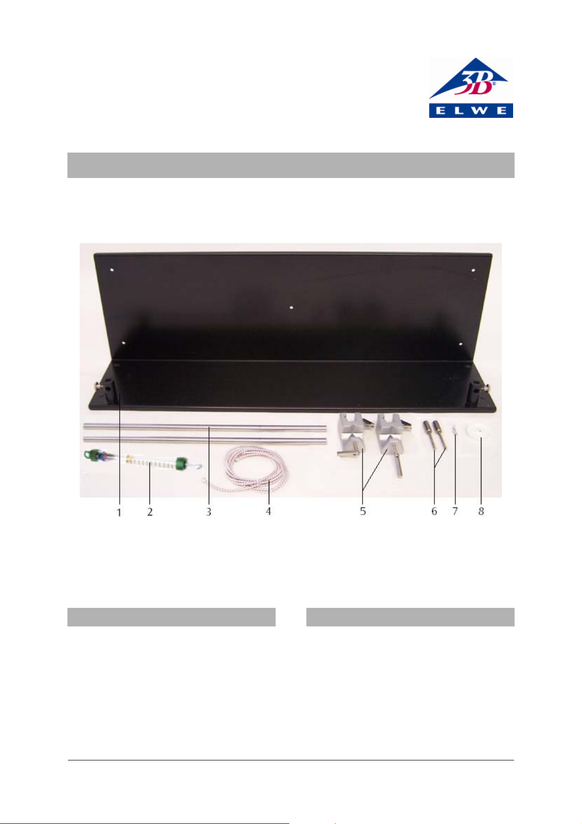
Seilwellengerät U8431776
1 Grundplatte
2
Kraftmesser
3 Stativstange
4 Gummiband
5 Universalmuffe
1. Beschreibung
Das Seilwellengerät dient zur Demonstration stehender Transversalwellen an einem Seil und zur
Untersuchung ihrer Wellenlänge in Abhängigkeit
der Seilspannung bei konstanter Frequenz.
Das gespannte Seil wird über einen von einem
Sinusgenerator angesteuerten Gleichstrommotor
zur Schwingung angeregt.
Mit dem Gerätesatz lässt sich zeigen, dass die Wellenlänge λ eines mit der Kraft F gespannten Seils
halb so groß ist wie bei vierfacher Spannkraft.
6
Achszapfen
7
Achsklemmen
8 Umlenkrolle
2. Lieferumfang
1 Grundplatte zum Seilwellengerät
1 Gummiband
2 Achszapfen
1 Umlenkrollen
1 Achsklemme
2 Vierkantmuffen
2 Stativstangen, 400 mm
1 Kraftmesser 5 N
1
Page 2
3. Bedienung
Zur Durchführung der Experimente sind folgende
Geräte zusätzlich erforderlich:
1 Gleichstrommotor U8552330
1 Sinusgenerator U8533550
1 Transformator (230 V, 50/60 Hz) U8475430-230
oder
1 Transformator (115 V, 50/60 Hz) U8475430-115
Experimentierkabel
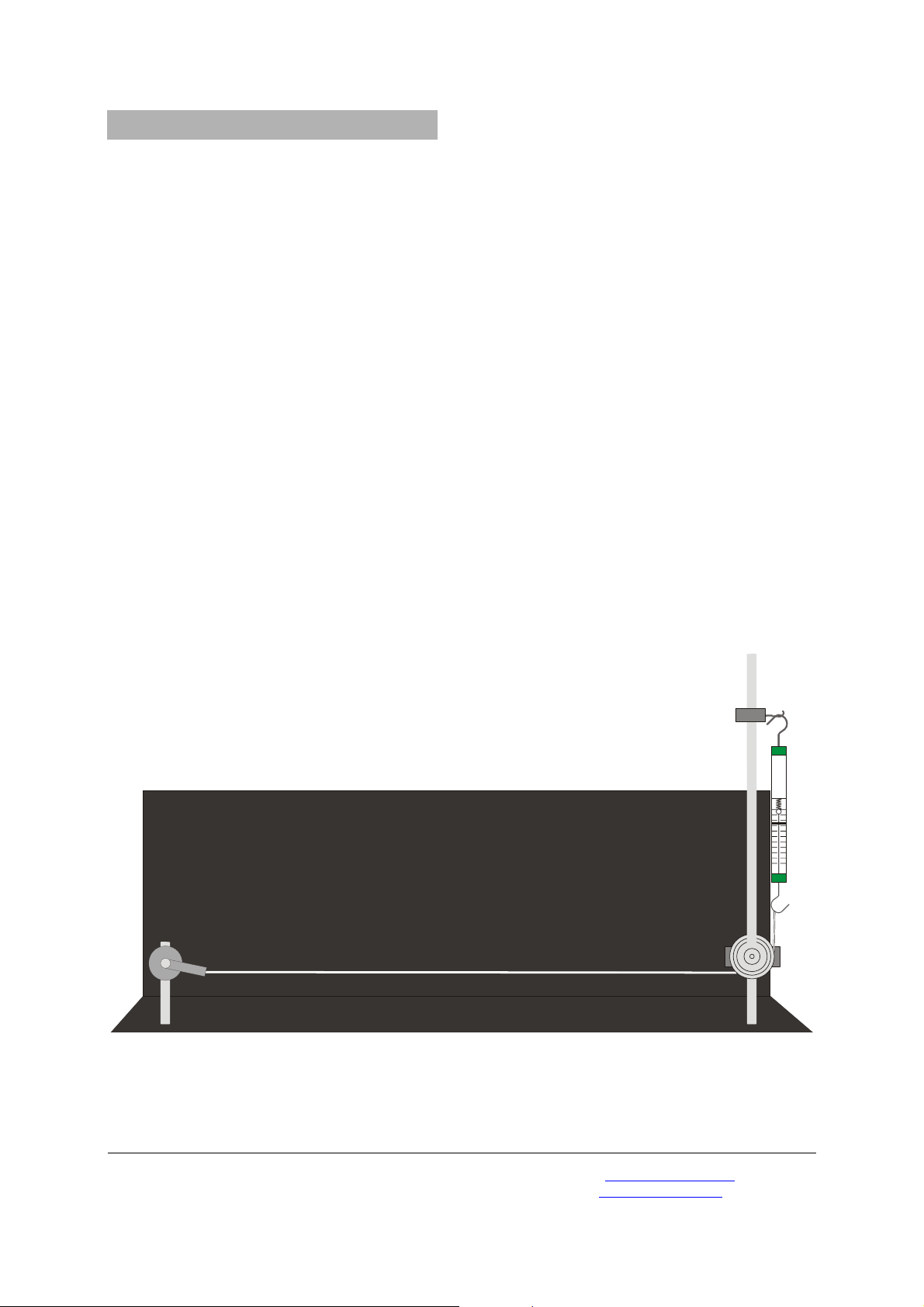
3.1 Aufbau
• Experimentellen Aufbau gemäß Fig. 1 herstel-
len.
• Gleichstrommotor in den linken Sockel für
Stativstangen einsetzen und festklemmen.
• Stativstangen zusammen schrauben, in den
rechten Sockel einsetzen und festklemmen.
• Universalmuffen an der Stativstange befesti-
gen.
• Umlenkrolle auf den Achszapfen schieben,
mittels der Achsklemme sichern und in der unteren Universalmuffe anbringen.
• Zweiten Achszapfen in der oberen Universal-
muffe befestigen und Kraftmesser anhängen.
• Gummiband am Gleichstrommotor befestigen,
unter der Umlenkrolle nach oben führen und
an den Kraftmesser hängen.
• Höhe der Umlenkrolle so einstellen, dass das
Gummiband parallel zur Grundplatte verläuft.
• Gleichstrommotor mit Sinusgenerator verbin-
den und diesen an den Transformator anschließen.
3.2 Durchführung
• Schalter S2 und S3 am Sinusgenerator auf Ge-
nerator (rechts) stellen.
• Seil mittels des Kraftmessers spannen.
• Frequenz am Sinusgenerator so einstellen, dass
sich 4 Schwingungsbäuche ausbilden. Mittels
Amplitudensteller Feineinstellung vornehmen.
Die Wellenlänge beträgt nun die halbe Seillänge.
• Kraftmesser am Stativstab nach oben verschie-
ben, bis die Seilspannung viermal so groß ist.
Am Seil bilden sich nun 2 Schwingungsbäuche aus.
Die Wellenlänge ist gleich der Seillänge.
Folgende Parameter liefern gute Ergebnisse:
Frequenz 42-43 Hz, anfängliche Seilspannung 0,5 N
Fig. 1 Experimenteller Aufbau
Elwe Didactic GmbH • Steinfelsstr. 6 • 08248 Klingenthal • Deutschland • www.elwedidactic.com
3B Scientific GmbH • Rudorffweg 8 • 21031 Hamburg • Deutschland • www.3bscientific.com
Technische Änderungen vorbehalten
© Copyright 2008 3B Scientific GmbH
Page 3
3B SCIENTIFIC
®
PHYSICS
Apparatus for Demonstrating Waves along a Cord U8431776
Instruction Sheet
07/08 ALF
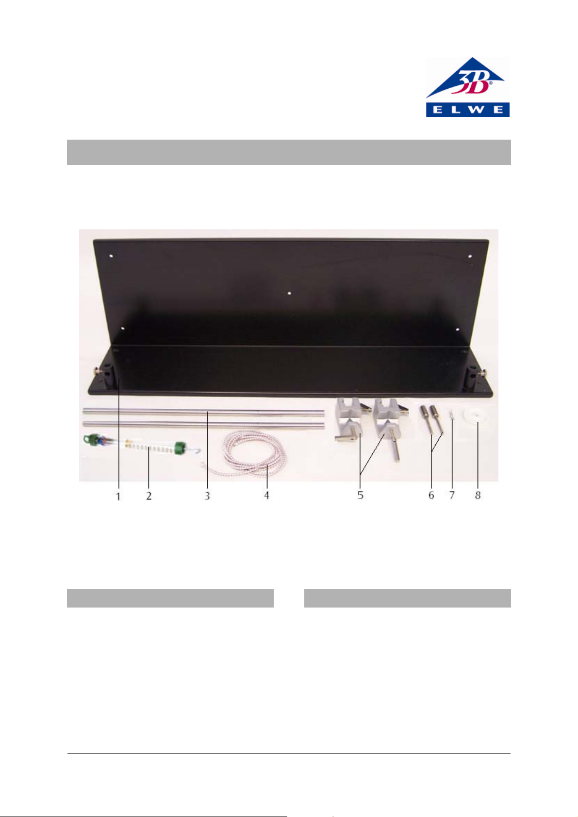
1 Base-plate
2 Dynamometer
3 Stand rods
4 Elastic cord
1. Description
The apparatus for demonstrating waves along a
cord shows how transverse standing waves can be
induced on a cord or string, and can be used to
investigate how their wavelength at a constant
frequency depends on the tension.
The stretched cord is induced to vibrate by a DC
motor driven by a sine-wave generator.
The instrument and accessories can be used to
show that the wavelength
under a tension F is halved when the tension is
increased by a factor of four.
λ
of a vibrating cord
5 Universal clamps
6 Axle rods
7 Axle clip
8 Pulley
2. Equipment supplied
1 Base-plate for apparatus
1 Elastic cord
2 Axle rods
1 Pulley
1 Axle clip
2 Universal clamps
2 Stand rods, 400 mm
1 Dynamometer, 5 N
1
Page 4
3. Operation
The following additional equipment is needed to
carry out the experiments:
1 DC motor U8552330
1 Sine-wave generator U8533550
1 Transformer, 12 V, 25 VA U8475430-230
or
1 Transformer, 12 V, 25 VA U8475430-115
Experiment leads
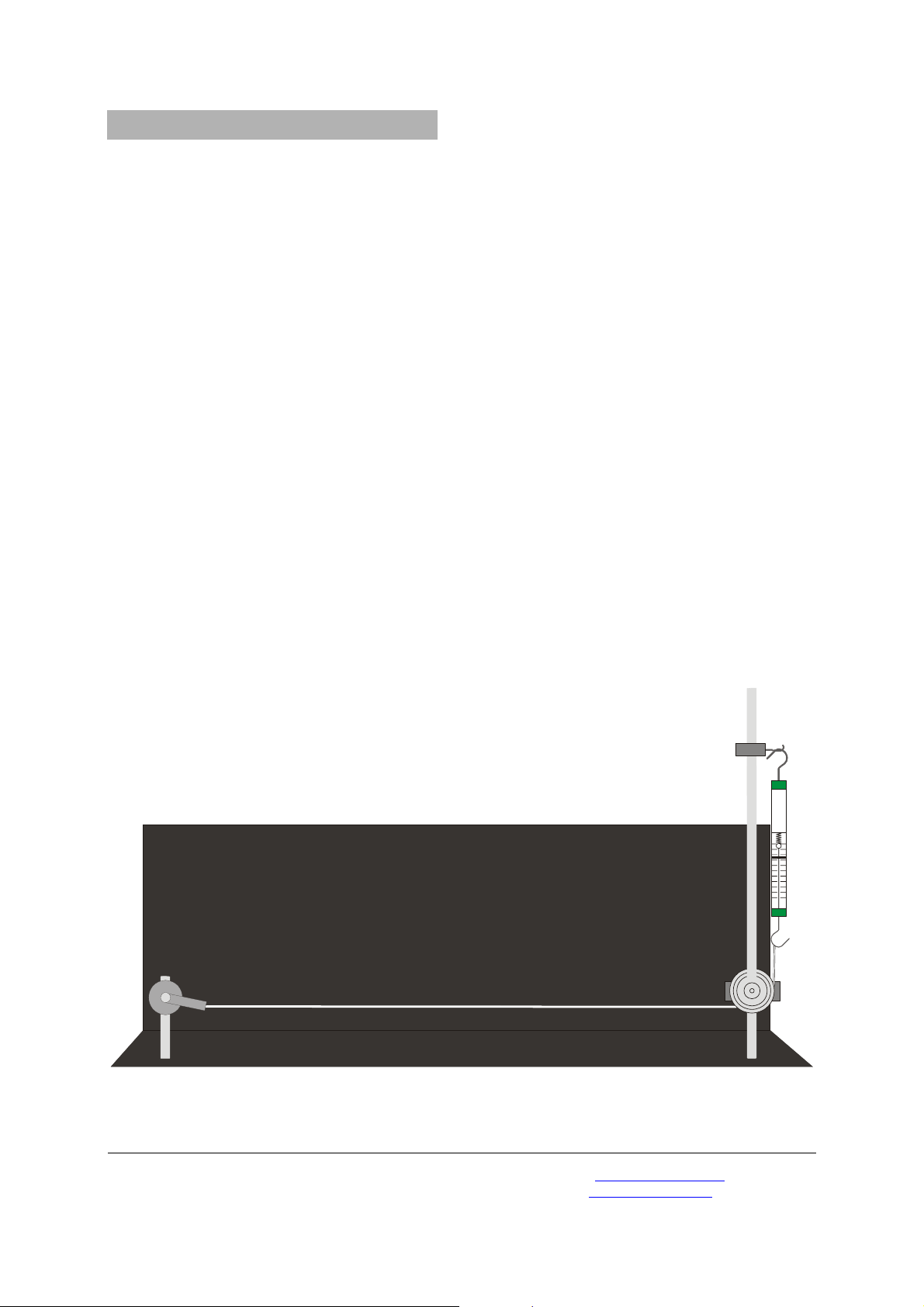
3.1 Setting up
• Set up the experiment as shown in Figure 1.
• Insert the DC motor into the left-hand rod
socket and secure it.
• Screw the two stand rods together, insert into
the right-hand socket, and secure them.
• Fix the two universal clamps to the rods.
• Push the pulley onto an axle-rod, secure it with
the axle clip, and fix it in the lower universal
clamp.
• Fix the second axle rod in the upper universal
clamp and suspend the dynamometer from it.
• Attach the elastic cord to the DC motor, pass it
under the pulley then up to attach it to the
dynamometer.
• Adjust the height of the pulley so that the
elastic cord runs parallel to the base-plate.
• Connect the DC motor to the sine-wave
generator and connect the latter to the
transformer.
3.2 Experiment procedure
• Set switches S2 and S3 of the sine-wave
generator to the “generator” position (right).
• Apply no tension to the cord other than by
means of the dynamometer.
• Adjust the frequency of the sine-wave
generator until a standing-wave vibration with
four peaks and troughs (two each) settles in.
Use the amplitude control to make fine
adjustments.
The wavelength is now half the length of the cord.
• Move the dynamometer higher up the rod until
the tension is four times the previous value.
The band now vibrates with just one peak and one
trough. The wavelength is therefore equal to the
length of the band.
The following parameters are found to give good
results:
Frequency: 42-43 Hz, initial cord tension: 0.5N.
Fig. 1 Experiment set-up
Elwe Didactic GmbH • Steinfelsstr. 6 • 08248 Klingenthal • Germany • www.elwedidactic.com
3B Scientific GmbH • Rudorffweg 8 • 21031 Hamburg • Germany • www.3bscientific.com
Subject to technical amendments
© Copyright 2008 3B Scientific GmbH
Page 5

3B SCIENTIFIC
Appareil à ondes de corde U8431776
Instructions d'utilisation
07/08 ALF
®
PHYSICS
1 Plaque d'assise
2 Dynamomètre
3 Barre de support
4 Bande en caoutchouc
1. Description
L'appareil à ondes de corde sert à la démonstration
des ondes transversales sur une corde et à l'étude
de leur longueur d'onde en fonction de la tension
de la corde à fréquence constante.
La corde tendue se met à osciller par l'action d'un
moteur à courant continu activé par un générateur
d'ondes sinusoïdales.
L'ensemble montre que la longueur d'onde λ
d'une corde tendue avec la force F est deux fois
moins grande que si la corde était tendue à une
force quatre fois plus élevée.
5 Noix universelle
6
Pivots
7
Fixations
8 Poulie de renvoi
2. Matériel fourni
1 plaque de base de l'appareil
1 bande en caoutchouc
2 pivots
1 poulie de renvoi
1 fixation
2 manchons carrés
2 barres de support 400 mm
1 dynamomètre 5 N
1
Page 6

3. Manipulation
Pour réaliser les expériences, vous nécessitez le
matériel supplémentaire suivant :
1 moteur à courant continu U8552330
1 générateur d'ondes sinusoïdales U8533550
1 transformateur U8475430-230
ou
1 transformateur U8475430-115
Câble d'expérimentation
3.1 Montage
• Réalisez le montage expérimental comme le
montre la figure 1.
• Insérez et fixez le moteur à courant continu
dans le socle gauche pour les barres de
support.
• Assemblez les barres de support en les vissant,
placez et fixez-les dans le socle de droite.
• Fixez les noix universelles à la barre de
support.
• Glissez la poulie de renvoi sur le pivot, serrez-la
avec la fixation et disposez-la dans la noix
universelle inférieure.
• Fixez le second pivot dans la noix universelle
supérieure et accrochez le dynamomètre.
• Fixez la bande en caoutchouc au moteur à
courant continu, faites-la passer vers le haut
sous la poulie de renvoi et accrochez-la au
dynamomètre.
• Réglez la hauteur de la poulie de renvoi de
manière à ce que la bande en caoutchouc soit
parallèle à la plaque de base.
• Connectez le moteur à courant continu au
générateur d'ondes sinusoïdales et branchez
celui-ci au transformateur.
3.2 Réalisation
• Réglez les interrupteurs S2 et S3 du générateur
d'ondes sinusoïdales sur Générateur (à droite).
• Tendez la corde avec le dynamomètre.
• Réglez la fréquence sur le générateur d'ondes
sinusoïdales de sorte qu'il se forme 4 ventres
d'oscillation. Procédez au réglage fin avec un
régulateur d'amplitude.
À présent, la longueur d'onde ne représente
qu'une demi-longueur de corde.
• Déplacez le dynamomètre sur la barre de
support vers le haut, jusqu'à ce que la tension
de la corde soit quatre fois plus élevée.
Sur la corde, il se forme désormais 2 ventres
d'oscillation. La longueur d'onde est égale à la
longueur de corde.
Les paramètres suivants fournissent de bons
résultats :
fréquence 42-43 Hz, tension de corde initiale 0,5 N.
Fig. 1 Montage expérimental
Elwe Didactic GmbH ▪ Steinfelsstr. 6 ▪ 08248 Klingenthal ▪ Allemagne ▪ www.elwedidactic.com
3B Scientific GmbH ▪ Rudorffweg 8 ▪ 21031 Hamburg ▪ Allemagne ▪ www.3bscientific.com
Sous réserve de modifications techniques
© Copyright 2008 3B Scientific GmbH
Page 7

3B SCIENTIFIC
Apparecchio per onde di corda U8431776
Istruzioni per l'uso
07/08 ALF
®
PHYSICS
1 Piastra di base
2 Dinamometro
3 Asta di supporto
4 Nastro di gomma
1. Descrizione
L’apparecchio per onde di corda serve per la
dimostrazione delle onde stazionarie trasversali su
una corda e per l’analisi della relativa lunghezza
d’onda in funzione della tensione della corda a
frequenza costante.
La corda tesa viene messa in oscillazione mediante
un motore a corrente continua azionato da un
generatore sinusoidale.
Con il kit è possibile dimostrare che la lunghezza
d’onda λ di una corda tesa con forza F è pari alla
metà del valore raggiunto con una forza di
tensione quattro volte superiore.
5 Manicotto universale
6
Perni assiali
Morsetto assiale
7
8 Rullo di rinvio
2. Fornitura
1 piastra di base dell’apparecchio per onde di
corda
1 nastro di gomma
2 perni assiali
1 rullo di rinvio
1 morsetto assiale
2 manicotti quadrati
2 aste di supporto, 400 mm
1 dinamometro 5 N
1
Page 8

3. Utilizzo
Per l'esecuzione degli esperimenti sono inoltre
necessari i seguenti apparecchi:
1 motore a corrente continua U8552330
1 generatore sinusoidale U8533550
1 trasformatore (230 V, 50/60 Hz) U8475430-230
o
1 trasformatore (115 V, 50/60 Hz) U8475430-115
Cavo per esperimenti
3.1 Struttura
• Realizzare una struttura sperimentale come
indicato in Fig. 1.
• Inserire e fissare il motore a corrente continua
nell’attacco sinistro per le aste di supporto.
• Avvitare l’una all’altra le aste di supporto,
inserirle nell’attacco destro e bloccarle.
• Fissare i manicotti universali all'asta di
supporto.
• Infilare il rullo di rinvio nel perno assiale,
assicurarlo con il morsetto assiale e fissare il
tutto al manicotto universale inferiore.
• Fissare il secondo perno assiale al manicotto
universale superiore e agganciare il
dinamometro.
• Fissare il nastro di gomma al motore a corrente
continua, farlo passare sotto al rullo di rinvio
portandolo verso l’alto e agganciarlo al
dinamometro.
• Regolare l’altezza del rullo di rinvio in modo
che il nastro di gomma scorra parallelamente
alla piastra di base.
• Collegare il motore a corrente continua con il
generatore sinusoidale e allacciare
quest’ultimo al trasformatore.
3.2 Esecuzione
• Posizionare gli interruttori S2 e S3 del
generatore sinusoidale su Generatore (a
destra).
• Tendere la corda mediante il dinamometro.
• Impostare la frequenza del generatore
sinusoidale in modo che si formino 4 ventri di
oscillazione. Eseguire la regolazione fine con il
regolatore di ampiezza.
La lunghezza d’onda è ora pari alla metà della
lunghezza della corda.
• Spostare il dinamometro verso l’alto lungo il
supporto stativo, fino a quadruplicare il valore
della tensione della corda.
Sulla corda si formano ora 2 ventri di oscillazione
e la lunghezza d’onda è pari alla lunghezza della
corda.
I seguenti parametri forniscono buoni risultati:
frequenza 42-43 Hz, tensione iniziale della corda
0,5 N
Fig. 1 Struttura sperimentale
Elwe Didactic GmbH • Steinfelsstr. 6 • 08248 Klingenthal • Germania • www.elwedidactic.com
3B Scientific GmbH • Rudorffweg 8 • 21031 Amburgo • Germania • www.3bscientific.com
Con riserva di modifiche tecniche
© Copyright 2007 3B Scientific GmbH
Page 9

3B SCIENTIFIC
Aparato de ondas en cuerdas U8431776
Instrucciones de uso
07/08 ALF
®
PHYSICS
1 Placa base
2 Dinamómetro
3 Varilla soporte
4 Banda de goma
1. Descripción
El aparato de ondas en cuerdas sirve para la
demostración de ondas transversales estacionarias
en una cuerda y para estudiar su longitud de onda
en dependencia con la tensión de la cuerda con
frecuencia constante.
En la cuerda tensa se excita una oscilación por
medio de un generador senoidal controlado por un
motor de corriente continua.
Con el juego de aparatos se puede demostrar que
la longitud de onda de una cuerda tensa por una
fuerza F se reduce a la mitad al cuadruplicar la
fuerza de tensión.
5 Nuez universal
6 Clavija de eje
7 Pinza de eje
8 Roldana de desviación
2. Volumen de entrega
1 Placa base para el aparato de ondas en cuerdas
1 Banda de goma
2 Clavija de eje
1 Roldana de desviación
1 Pinza de eje
2 Nuces cuadradas
2 Varillas soporte, 400 mm
1 Dinamómetro 5 N
1
Page 10

3. Manejo
Para la realización de experimentos se requieren
adicionalmente los siguientes aparatos:
1 Motor de continua U8552330
1 Generador senoidal U8533550
1 Transformador (230 V, 50/60 Hz) U8475430-230
o
1 Transformador (115 V, 50/60 Hz) U8475430-115
Cables de experimentación
3.1 Montaje
• Realice el montaje experimental según la Fig.
1.
• El motor de corriente continua se coloca y se
fija en el zócalo izquierdo para varillas soporte.
• Se atornillan entre sí las varillas soporte, se
colocan y se fijan en el zócalo derecho.
• Se fijan las nueces universales en la varilla
soporte.
• Se desliza la roldada de desviación en la clavija
de eje y se asegura por medio de la pinza de
eje y se lleva a la nuez universal inferior.
• Se fija la segunda clavija de eje en la nuez
universal superior y se cuelga de ella el
dinamómetro.
• Se fija la banda de goma en el motor de
corriente continua, se pasa por debajo de la
roldana de desviación, se conduce hacia arriba
y se cuelga del dinamómetro.
• Se ajusta la altura de la roldada de desviación
para que la banda de goma quede paralela a la
placa base.
• Se conecta el motor de continua con el
generador senoidal y éste último con el
transformador.
3.2 Realización
• Los conmtadores S2 y S3 en el generador
senoidal se ajustan en generador (a la
derecha).
• Se tensa la cuerda con el dinamómetro.
• Se ajusta la frecuencia en el generador
senoidal para que se creen cuatro vientres de
oscilación. Se hace un ajuste fino con el ajuste
de amplitud.
La longitud de onda es igual a la mitad de la
longitud de la cuerda.
• Se desplaza el dinamómetro hacia arriba hasta
que la tensión de la cuerda se cuadruplique.
En la cuerda se forman 2 vientres de oscilación. La
longitud de onda es igual a la longitud de la
cuerda.
Los siguientes parámetros entregan buenos
resultados: Frecuencia 42 – 43 Hz; tensión inicial
de la cuerda 0,5 N
Fig. 1 Experimenteller Aufbau
Elwe Didactic GmbH • Steinfelsstr. 6 • 08248 Klingenthal • Alemania • www.elwedidactic.com
3B Scientific GmbH • Rudorffweg 8 • 21031 Hamburgo • Alemania • www.3bscientific.com
Se reservan modificaciones técnicas
© Copyright 2008 3B Scientific GmbH
Page 11

3B SCIENTIFIC
Dispositivo de onda U8431776
Manual de instruções
07/08 ALF
®
PHYSICS
1 Placa base
2 Dinamômetro
3 Vara do tripé
4 Elástico
5 Pinos universais
1. Descrição
O dispositivo de onda serve para demonstrar as
ondas estáticas transversais em uma corda e para a
verificação do seu comprimento de onda em
dependência da tensão da corda em uma
freqüência constante.
A corda tensionada é levada a ondular através de
um gerador de onda de seno.
Com o conjunto da aparelhagem demonstra-se que
uma corda tensionada com o comprimento de
onda λ por uma força F é a metade do tamanho do
que quando são tensionadas quatro vezes mais.
6
Pino de eixo
7 Presilhas de eixo
8 Rolo direcional
2. Acessórios
1 Placa base para o dispositivo de onda
1 Elástico
2 Pinos de eixo
1 Rolo direcional
1 Presilha de eixo
2 Pinos de quatro cantos
2 Estruturas do tripé, 400 mm
1 Dinamômetro 5 N
1
Page 12

3. Operação
Para se realizar o experimento são necessários os
seguintes aparelhos:
1 Motor de corrente continua U8552330
1 Gerador de onda de seno U8533550
1 Transformador(230 V, 50/60 Hz) U8475430-230
ou
1 Transformador (115 V, 50/60 Hz) U8475430-115
Cabos para experiências
3.1 Montagem
• Montagem experimental conforme Fig. 1.
• Colocar o motor de corrente contínua no
soquete esquerdo da vara de tripé e prender.
• Aparafusar conjuntamente as varas de tripé,
posicionar no soquete direito e prender.
• Fixar os pinos universais nas varas de tripé.
• Empurrar o rolo direcional sobre os pinos de
eixo, assegurar através do prendedor de eixo e
colocar nos pinos universais inferior.
• Prender dois pinos de eixo no pino universal
superior e engatar o dinamômetro.
• Fixar o elástico no motor de corrente continua,
conduzir por baixo do rolo direcional para
cima e engatar no dinamômetro.
• Posicionar o rolo direcional de tal modo, que o
elástico fique paralelo á placa base.
• Conectar o motor de corrente contínua ao
gerador de onda de seno e ligar este no
transformador.
3.2 Execução
• Colocar os interruptores S2 e S3 no gerador de
onda seno em gerador (direita).
• Tencionar a corda através do dinamômetro.
• Colocar a freqüência no gerador de onda seno
de tal modo, que se formem 4 ondas de
oscilação. Realizar a sintonia fina através do
sintonizador de amplitude.
O comprimento de onda consiste agora da metade
do comprimento da corda.
• Empurrar o dinamômetro na vara do tripé para
cima, até que a tensão da corda seja
multiplicada por quatro.
Na corda vão se formar duas ondas. O
comprimento de onda é igual o comprimento da
corda.
Os seguintes parâmetros dão bons resultados:
Freqüência 42-43 Hz, tensão inicial da corda 0,5 N
Fig. 1 Montagem experimental
Elwe Didactic GmbH • Steinfelsstr. 6 • 08248 Klingenthal • Alemanha • www.elwedidactic.com
3B Scientific GmbH • Rudorffweg 8 • 21031 Hamburgo • Alemanha • www.3bscientific.com
Sob reserva de alterações técnicas
© Copyright 2008 3B Scientific GmbH
 Loading...