

Page 1
3B SCIENTIFIC
®
PHYSICS
Assembly Kit “Bell, Relay and Bimetallic Switch” U8497700
Instruction Sheet
06/08 SP/ALF
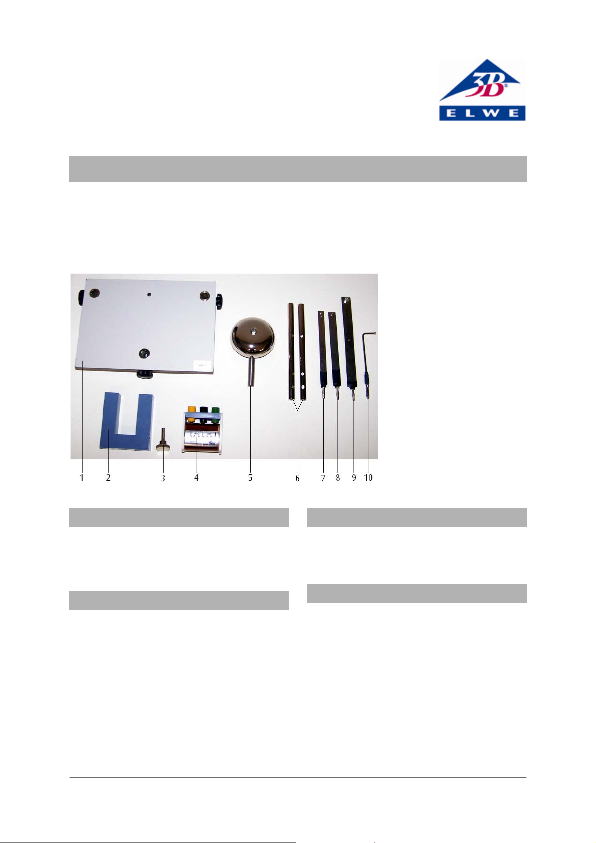
1 Base plate
2 U-core
3 Fixing screw for U-core
4 Coil
5 Bell
6 Contact rods
7 Bimetallic strip
Armature
8
9 Leaf spring
10 Contact pin
1. Description
The bell, relay and bimetallic switch assembly kit is
used to construct different types of electromagnetic
switches and bimetallic strip switches.
2. Equipment supplied
1 Base-plate with three fixing positions
1 Bell, 70 mm diameter
2 Contact rods, each with three 4 mm holes
1 Leaf spring with plug
1 Bimetallic strip with plug
1 Armature with plug
1 Contact pin with plug
1 U-core, 20 × 20 mm²
1 Fixing screw for U-core
1 Coil, 800 turns.
3. Technical data
Base plate dimensions: 200×140×40 mm3 approx.
Weight: 1.6 kg approx.
4. Example switch assemblies
To assemble the switches the following additional
equipment is needed:
1 Transformer with rectifier (230 V, 50/60 Hz)
U33300-230
or
1 Transformer with rectifier (115 V, 50/60 Hz)
U33300-115
1 Lamp socket E14 U8495320
1 Filament lamp, 12 V, 25 W, E14, as typical consumer item
1
Page 2
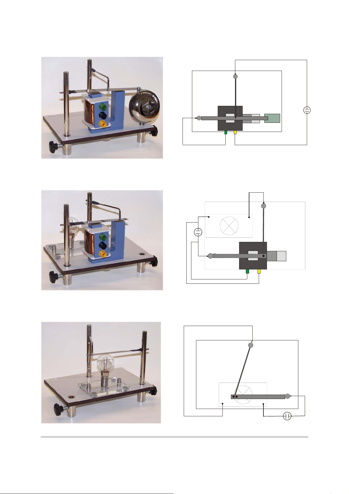
4.1 Assembly of a bell circuit
Fig 1 Assembly of a bell circuit
4.2 Assembly of a relay
Fig. 2 Circuit diagram for a bell
Fig 3 Assembly of a relay
4.3 Assembly of a bimetallic switch circuit
Fig. 5 Assembly of a bimetallic switch circuit
Elwe Didactic GmbH ▪ Steinfelsstr. 6 ▪ 08248 Klingenthal ▪ Germany ▪ www.elwedidactic.com
3B Scientific GmbH ▪ Rudorffweg 8 ▪ 21031 Hamburg ▪ Germany ▪ www.3bscientific.com
Subject to technical amendments
© Copyright 2008 3B Scientific GmbH
Fig. 4 Circuit diagram for a relay
Fig. 6 Circuit diagram for a bimetallic switch
 Loading...