

Page 1
U17451 Analog Multimeter
Instruction sheet
10/04 MC/ALF
3
4
5
2
1
Handheld meter used to measure
current, voltage and resistance as
well as gain levels or attenuation e.g.
in chains of quadripoles.
1. Safety instructions
• Before using the analog multime-
ter, make sure you read the operating instructions carefully and
that you comply with them completely.
• The safety of the multimeter and
the person operating it can only
be guaranteed if it is used in accordance with the instructions. Do
not operate or handle this unit
incorrectly or inappropriately.
• The device may only be used by
persons, who are aware of the hazards of contact (for voltages over
30 V rms) and can undertake the
appropriate safety precautions.
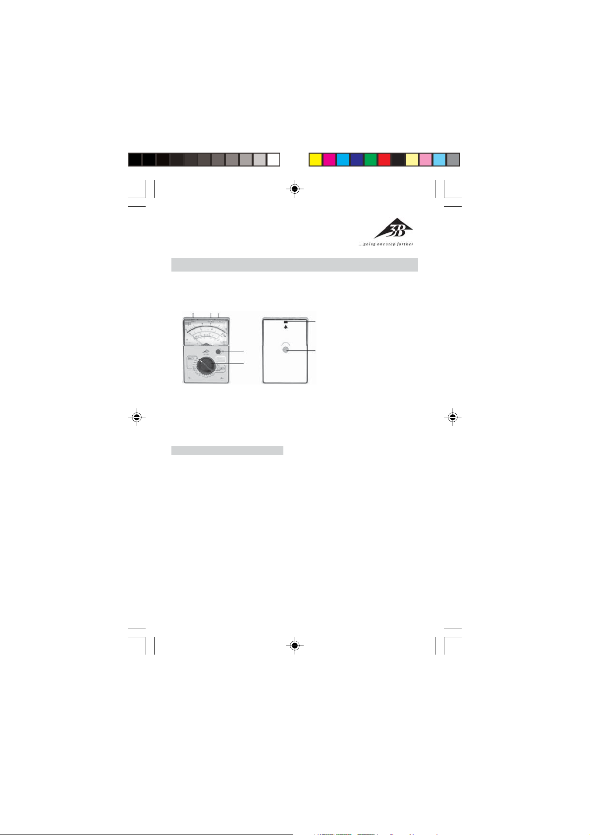
1 Rotary switch to select
measurement range
2 Rotary knob to set full-scale
7
deflection for 0 Ω
3 Connection for voltage
measurement
4 Connection for current and
6
This also includes the appearance
of unforeseen voltages e.g. in defective units or charged capacitors.
• In the case of voltage and current
measurements the nominal voltage between the phase and neutral conductor may not exceed 300
V according to CAT II (in circuits
that are directly connected to the
mains) and CAT III (in building wiring installations) 300 V.
• The analog multimeter may not be
used for measurements in circuits
with corona discharge (high voltage).
• In measurements involving RF cir-
cuits special care must be taken
due to the existence of dangerous
hybrid voltages.
• The appropriate permissible mea-
surement range may not be exceeded. Always change from a
resistance measurement
5 Connection for ground
6 Adjustment screw for
mechanical zero-point
setting
7 Nub to latch the housing
shut
6
Page 2
higher measurement range to a
lower measurement range.
• Before using the device, check the
housing and the measurement
cables for any damage.
• Do not conduct measurements in
a damp environment. Workplace,
hands, shoes and floor must be dry.
• Before opening the housing all
measurement leads are disconnected from the device.
2. Description, technical data
Passive analog multimeter with a
rotary switch for selecting the measurement ranges and a scale with
mirrored background for parallaxfree readings. The device is extremely robust in terms of load capacity
and is equipped with excellent overload protection due to its two antiparallel diodes as well as moving coil
movement, which is not sensitive to
external electromagnetic fields. The
safety connection sockets offer protection against accidental touch contact. The robust plastic housing and
the spring-connected bearing jewels
of the movement guarantee protection against damage caused by mechanical stress.
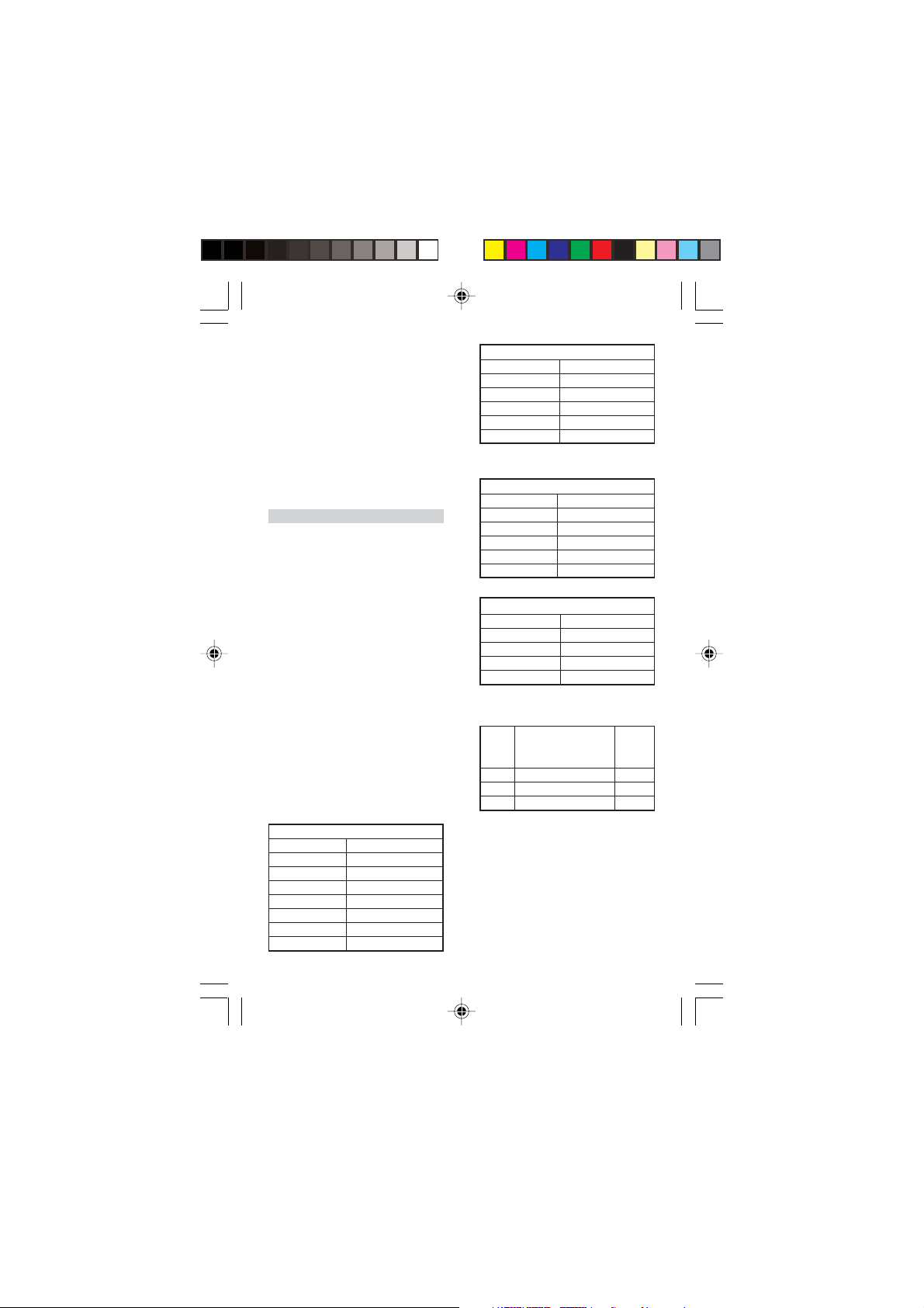
Measurement ranges:
Voltage measurement:
DC
Meas. range Int. resistance
100 mV 2 kΩ
1 V 20 kΩ
10 V 200 kΩ
30 V 600 kΩ
100 V 2 MΩ
300 V 6 MΩ
600 V 12 MΩ
Meas. range Int. resistance
AC
10 V 66,7 kΩ
30 V 200 kΩ
100 V 667 kΩ
300 V 2 MΩ
600 V 4 MΩ
Current measurement:
DC
Meas. range Voltage drop
50 µA 100 mV
1 mA 500 mV
10 mA 500 mV
100 mA 500 mV
1 A 190 mV
AC
Meas. range Voltage drop
3 mA 1.5 V
30 mA 1.6 V
300 mA 1.6 V
3 A 1.8 V
Resistance measurement:
Max.
Rotary Meas. range meas.
switch and scale center current
Ω x 1 1 Ω...35 kΩ...5 kΩ 45 mA
Ω x 10 10 Ω...350 kΩ...50 kΩ 4.5 mA
Ω x 100100 Ω...3.5 kΩ...500 kΩ 0.45 mA
Accuracy: Class 2,5
Influencing variables and nominal
operating ranges:
Temperature 0 – 40° C:
± 1% / 10 K for DC; ± 2.5% / 10 K
for 100 mV/50 µA DC; ± 1.5% / 10 K
for AC
Frequency (30 Hz...1 kHz): ± 2.5%
Reference conditions:
7
Page 3

Ambient temperature: + 23° C
1
V
50
A
+
+
Frequency:50...60 Hz
Waveform: Sinusoidal
Electrical safety:
Safety stipulations: EN 61010-1
Overvoltage category:
CAT III max. 300 V; CAT II max. 600 V
Degree of pollution: 2
Overload protection: F3 fuse, 15 A/
500 V (IEC127)
Electromagnetic compatibility:
Jamming: EN 500081-2
Interference immunity: EN 500082-2
Power supply: 1 x 1.5 V Batterie IEC
R6
Dimensions: 98x138x35 mm
Ground: approx. 0,25 kg
3. Operation
3.1 Readying for use
• Insert battery into the battery
compartment. To do this open the
appropriate section of the housing
by pressing in the nub (7), e.g. using a screwdriver. Then insert the
battery and connected it to the
battery clip. Replace the section of
housing and snap it into place.
• Check the mechanical zero-point.
The measuring instrument may
not be connected to anything at
this time. The needle must be located in the zero-point position
when the multimeter is in a horizontal position. If necessary make
the corresponding adjustments by
means of the adjustment screw (6).
• Check the full scale deflection setting for 0 Ω. To do this set the rotary switch (1) to “x 1 Ω”. Shortcircuit the connection sockets
“COM” (5) and “
µ
A, Ω” (4). Set
00m
the full scale deflection by turning the knob (2).
• If full scale deflection cannot be
set or the needle no longer stays
still, the battery must be replaced.
3.2 General instructions
• When performing measurements
always set the rotary switch (1) to
the highest measurement range.
Then turn to lower ranges until the
optimum needle deflection is obtained.
• When the multimeter is not in use,
disconnect all measurement leads
from the meter, reset the rotary
switch (1) to the highest range and,
if necessary, remove the battery.
3.3 Voltage measurement
3.3.1 DC voltage up to 100 mV
_
V
COM
AΩ
• Set the rotary switch (1) to the
measurement range “50 µA,
100 mV”.
• Connect the multimeter and take
a reading from the V, A DC scale.
3.3.2 DC voltage up to 600 V
_
V
COM
• Using the rotary switch (1) select
the corresponding measurement
range “600,...,1 V DC”.
AΩ
8
Page 4

• Connect the multimeter and take
~
+
~
1
V
50
A
a reading from the V, A DC scale.
3.3.3 AC voltage up to 600 V
V
COM
AΩ
• Using the rotary switch (1) select
the corresponding measurement
range “600,...,10 V AC”.
• Connect the multimeter and take
a reading from the V, A AC scale.
3.4 Current measurement
• When taking any current measurements connect the multimeter in
series to the load in the circuit,
which has the least potential with
respect to ground.
• Measurements conducted in the 3
A range may not take longer than
1 min.
3.4.1 Direct current up to 1 A
_
V
COM
• Using the rotary switch (1) select
the corresponding measurement
range “1 A,...,50 µA DC”.
• Connect the multimeter and take
a reading on the V, A, DC scale.
3.4.2 Alternating current up to 3 A
AΩ
• Using the rotary switch (1) select
the corresponding measurement
range “3 A,...,3 mA AC”.
• Connect the multimeter and take
a reading on the V, A, AC scale.
3.5 Measuring resistance
_
COM
+
V
AΩ
• Using the rotary switch (1) select
the corresponding measurement
range “x 100 Ω,..., x 1 Ω”.
• Connect the multimeter and take
a reading on the Ù scale.
• When performing measurement
on semiconductors use the following terminals: positive pole connected to “COM” and negative pole
connected “
• Resistance measurement is carried
00m
µ
A, Ω”.
out using the DC voltage from the
battery being used. Since the battery is under extreme loading during measurements in the “x 1 Ω”
range, the measurement should
only be of a brief duration.
• Only measure zero-voltage ele-
ments due to the fact that external voltages falsify measured values.
• When resistances measurements
are carried out involving longer
periods and switchover to other
measurement ranges is complete
check for 0 Ω full scale deflection
and adjust, if necessary.
V
COM
AΩ
9
Page 5

3.6 Attenuation and gain
~
measurement
V
COM
AΩ
• In communications engineering
the gain or attenuation of a signal
is specified in decibels as the logarithm of the ratio between the
measured voltage and a defined
reference voltage. Positive values
correspond to a gain and negative
values reflect attenuation. The reference voltage of the multimeter
amounts to 0.775 V (= 1 mW at
600 Ω). With this voltage there is
a gain of 0 dB.
• Using the rotary switch (1) select
the corresponding measurement
range “600,..., 10 V AC”.
• Connect the multimeter and take
a reading on the dB scale.
• Since this scale is only valid for the
10 V measurement range, in the
other measurement ranges a relative constant must be added to the
value obtained from the scale:
Meas. range Constants
30 V 10 dB
100 V 20 dB
300 VB 30 dB
600 V 36 dB
4 Maintenance
4.1 Cleaning
• Only use a paintbrush or soft tow-
el to clean the multimeter. If static electrical charging occurs on the
view window this can be eliminated using a damp rag or an antistatic agent.
4.2 Battery
• Test the battery from time to time.
If it is dead or it has started to decompose, it must be removed from
the device. The battery is replaced
in accordance with 3.1.
• If the multimeter remains idle
over a long period of time, the
battery should be removed from
the unit.
4.3 Replacing the fuse
• The multimeter is equipped with
a safety fuse F3,15 A/500 V. To replace the fuse the device must be
opened as described in section 3.1.
Remove the fuse and replace it
with a fuse of identical type. Then
replace the section of housing and
snap it back into place securely.
3B Scientific GmbH • Rudorffweg 8 • 21031 Hamburg • Ger many • www.3bscientific.com • Technical amendments are possible
10
 Loading...