

Page 1

3B SCIENTIFIC3B SCIENTIFIC
3B SCIENTIFIC®
3B SCIENTIFIC3B SCIENTIFIC
PHYSICSPHYSICS
PHYSICS
PHYSICSPHYSICS
U17450 Analog-Multimeter Nullpunkt Mitte/links
Bedienungsanleitung
10/04 MC/ALF
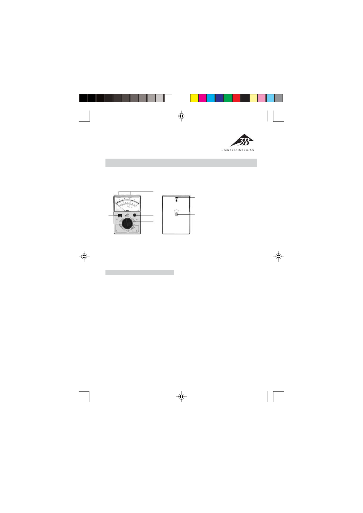
1 Drehschalter zur Wahl des
3
4
2
1
Messbereichs
2 Drehknopf zur elektrischen
6
Nullpunktseinstellung in
Skalenmitte
3Sicherheits-Anschlussbuchsen
5
4 Schiebeschalter zur Wahl der
Betriebsart
5 Stellschraube zur
mechanischen Nullpunktseinstellung
6 Nase zur Verriegelung des
Gehäuses
Handmessgerät zur Messung von
Strom und Spannung.
1. Sicherheitshinweise
• Vor Einsatz des Analog-Multimeters
ist die Bedienungsanleitung sorgfältig und vollständig durchzulesen
und in allen Punkten zu befolgen.
• Die Sicherheit des Multimeters und
des Bedienenden sind bei bestimmungsgemäßer Verwendung gewährleistet. Gerät nicht unsachgemäß oder unachtsam behandeln.
• Das Gerät darf nur von Personen
verwendet werden, die Berührungsgefahren (bei Spannungen über 30 V
Effektivwert) erkennen und entsprechende Sicherheitsvorkehrungen
treffen können. Dazu zählen auch
unvorhergesehene Spannungsauftretung z.B. bei defekten Geräten
oder geladenen Kondensatoren.
• Die Nennspannung zwischen Pha-
se und Nulleiter darf bei Spannungs- und Strommessungen nach
CAT II (in Stromkreisen, die elektrisch direkt mit dem Netz verbunden sind) und CAT III (in der Gebäudeinstallation) 300 V nicht überschreiten.
• Das Analog-Multimeter darf nicht
zur Messung in Stromkreisen mit
Koronaentladung (Hochspannung)
eingesetzt werden.
• Bei Messungen in HF-Stromkreisen
besondere Vorsicht walten lassen,
da das Vorhandensein gefährlicher
Mischspannungen besteht.
• Der zulässige Messbereich darf
nicht überschritten werden. Von
einem höheren Messbereich in einen niedrigeren wechseln.
• Vor Einsatz des Geräts sind das Ge-
1
Page 2
häuse und die Messleitungen auf
Beschädigung zu untersuchen.
• Keine Messungen in feuchter Um-
gebung durchführen. Arbeitsplatz,
Hände, Schuhe und Fußboden
müssen trocken sein.
• Bevor das Gehäuse geöffnet wird
sind die Messleitungen vom Gerät
zu trennen.
2. Beschreibung, technische Daten
Aktives Analog-Multimeter mit einem Schiebeschalter für die Betriebsart und einem Drehschalter für
die Messbereichsauswahl sowie
spiegelunterlegter Skala für parallaxenfreie Ablesung und einstellbarem Skalennullpunkt Mitte / links.
Durch die Einstellung des elektrischen Nullpunkts in Skalenmitte
können bipolare Gleichspannungsund Gleichstrommessungen ohne
Beachtung der Polarität durchgeführt werden. Das Gerät ist hochbelastbar und verfügt über einen ausgezeichneten Überlastschutz durch
zwei antiparallele Dioden sowie ein
gegenüber Fremdfeldern unempfindliches Drehspulmesswerk. Die
Sicherheits-Anschlussbuchsen bieten Schutz vor zufälligem Berühren.
Nach ca. 45 min erfolgt automatische Batterieabschaltung. Wiederherstellung der Stromversorgung
geschieht durch Aus- und Einschalten des Betriebsart-Schiebeschalters. Das robuste Kunststoffgehäuse
und die gefederten Lagersteine des
Drehspulmesswerks gewährleisten
Schutz vor Beschädigung und mechanischer Beanspruchung.
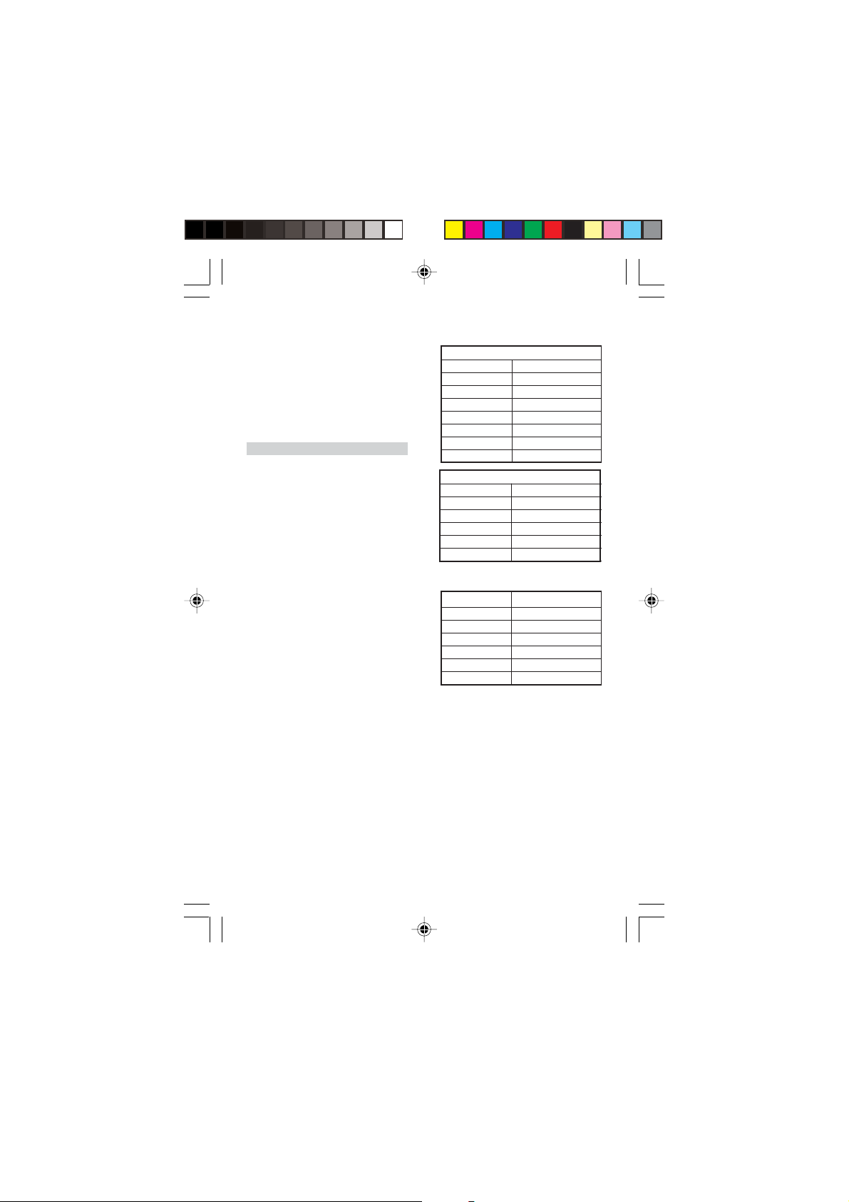
Messbereiche:
Spannungsmessung:
DC
Messbereich Innenwiderstand
100 mV 10 MΩ
300 mV 10 MΩ
1 V 10 MΩ
3 V 10 MΩ
10 V 10 MΩ
100 V 10 MΩ
300 V 10 MΩ
AC
Messbereich Innenwiderstand
3 V 1 MΩ
10 V 1 MΩ
30 V 1 MΩ
100 V 1 MΩ
300 V 1 MΩ
Strommessung AC/DC:
Messbereich Spannungsabfall
0,1 mA 55 mV
1 mA 55 mV
10 mA 55 mV
100 mA 55 mV
1 A 53 mV
3 A 51 mV
Genauigkeit: DC Klasse 2; AC Klasse 3
Einflussgrößen und Nenngebrauchsbereiche:
Temperatur 0 – 40° C: ± 2% / K
Frequenz für sämtliche
Messbereiche: ± 2,5% bei 30 Hz
bis 1,5 kHz
± 5% bei 1,5 kHz
bis 3 kHz
Referenzbedingungen:
Umgebungstemperatur: + 23° C ± 2 K
Frequenz: 50 bis 60 Hz
Kurvenform: Sinus
2
Page 3
Überlastschutz:
+
Sicherung F3, 15 H/250 V nach DIN
VDE 0820 Teil 22/EN 60 127-2 als
Stromkreisschutz bei Überlastung;
Messwerk geschützt mit 2
antiparallel geschalteten Dioden
Schutzklasse:
IEC 1010-1/EN 61010-1/ VDE 0411-1
Überspannungskategorie: CAT III
Nennspannung: 300 V
Verschmutzungsgrad: 2
Prüfspannung: 3,7 kV~
EMV:Elektromagnetische
Verträglichkeit
Störsendung: EN 50081-1:1992
Störfestigkeit: EN 50082-1:1992
Stromversorgung: 1 x 9 V Flachzellenbatterie, IEC 6F22
Abmessungen: 98x138x35 mm
Masse: ca. 0,3 kg
3. Bedienung
3.1 Inbetriebnahme
• Batterie ins Batteriefach einset-
zen. Dazu Gehäuseteil abnehmen,
indem die Nase (6) z.B. mit einem
Schraubenzieher nach innen gedrückt wird. Dann die Batterie einsetzen und mit dem Batterieclip
verbinden. Gehäuseteil wieder
aufsetzen und einrasten lassen.
• Mechanischen Nullpunkt kontrol-
lieren. Dabei darf das Messgerät
nicht angeschlossen sein. Schiebeschalter (4) in Position „0" bringen.
Zeiger muss bei waagerechter Lage
des Mulimeters in Position „
OFF” stehen. Gegebenenfalls mit
der Stellschraube (5) entsprechend
einstellen.
• Elektrischen Nullpunkt kontrollie-
ren. Schiebeschalter (4) in Position „ ” bringen. Messbereich wählen, Zeiger muss auf Nullpunkt in
Skalenmitte stehen, sonst mit dem
Drehknopf (2) korrigieren.
• Kontrolle der Batterie. Dazu Schie-
beschalter (4) in Position „ ”
bringen, Drehschalter (1) in Position „ ” stellen. Wenn der Zeiger nicht in das mit „ ” gekennzeichnete Batterietestfeld ausschlägt, muss ein Batteriewechsel
vorgenommen werden.
3.2 Allgemeine Hinweise
• Bei Messungen den Drehschalter
(1) immer auf den höchsten Messbereich stellen. Dann solange auf
niedrigere Bereiche drehen, bis optimaler Zeigerausschlag erreicht ist.
• Bei Unterbrechung der Stromver-
sorgung durch automatische Batterieabschaltung (nach ca.
45 min.) Schiebeschalter (4) erneut
aus- und einschalten.
• Bei Nichtbenutzung des Multime-
ters alle Messleitungen vom Messgerät entfernen, Drehschalter (1)
wieder auf den höchsten Bereich
einstellen, Schiebeschalter (4) in
Position „0" bringen, gegebenenfalls Batterie entnehmen.
3.3 Gleichspannungsmessung
_
3.3.1 Betriebsart: Elektrischer Nullpunkt links
• Schiebeschalter (4) in Position
„ ” bringen.
• Mittels Drehschalter (1) den ent-
sprechenden Messbereich „V...”
auswählen.
• Multimeter anschließen und Wert
3
Page 4
auf der oberen Skala ablesen.
_
+
3.3.2 Betriebsart: Elektrischer Nullpunkt Mitte
• Schiebeschalter (4) in Position
„ ” bringen.
• Mittels Drehschalter (1) den ent-
sprechenden Messbereich „V ...”
auswählen.
• Zeiger muss in Skalenmitte ste-
hen.
• Multimeter anschließen und Wert
auf der unteren Skala ablesen.
3.4 Wechselspannungsmessung,
direkt bis 300 V
~
• Schiebeschalter (4) in Position
„ ” bringen.
• Mittels Drehschalter (1) den ent-
sprechenden Messbereich „V~”
auswählen.
• Multimeter anschließen und Wert
auf der oberen Skala ablesen.
• Zur Verringerung des Frequenzein-
flusses wird die Anschlussbuchse
⊥⊥
„
⊥” direkt mit dem Erdpotential
⊥⊥
oder mit dem gegenüber Erdpotential niedrigsten Punkt verbunden.
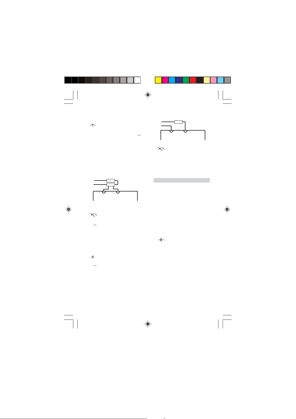
3.5 Messung der Wechselspan-
nung mit überlagerter Gleichspannung
~
• Mit Hilfe eines Kondensators
(empfohlen: 4,7 µF/630 V) kann
die z.B. bei einer Verstärkungsendstufe vorkommende Gleichspannungskomponente abgetrennt
werden. Der entstehende Messfehler liegt unter 0,2% bei einer Messfrequenz von 50 Hz.
• Gemessen wird wie unter 3.4 be-
schrieben.
• Messung der Gleichspannungs-
komponente erfolgt wie unter 3.3
beschrieben.
• Um Überlastung zu vermeiden
muss der eingestellte Messbereich
größer sein als die zuerst ermittelte Gleichspannungskomponente.
• Achtung: Vor Umschaltung in ei-
nen niedrigeren Messbereich müssen beide Spannungskomponenten geprüft werden.
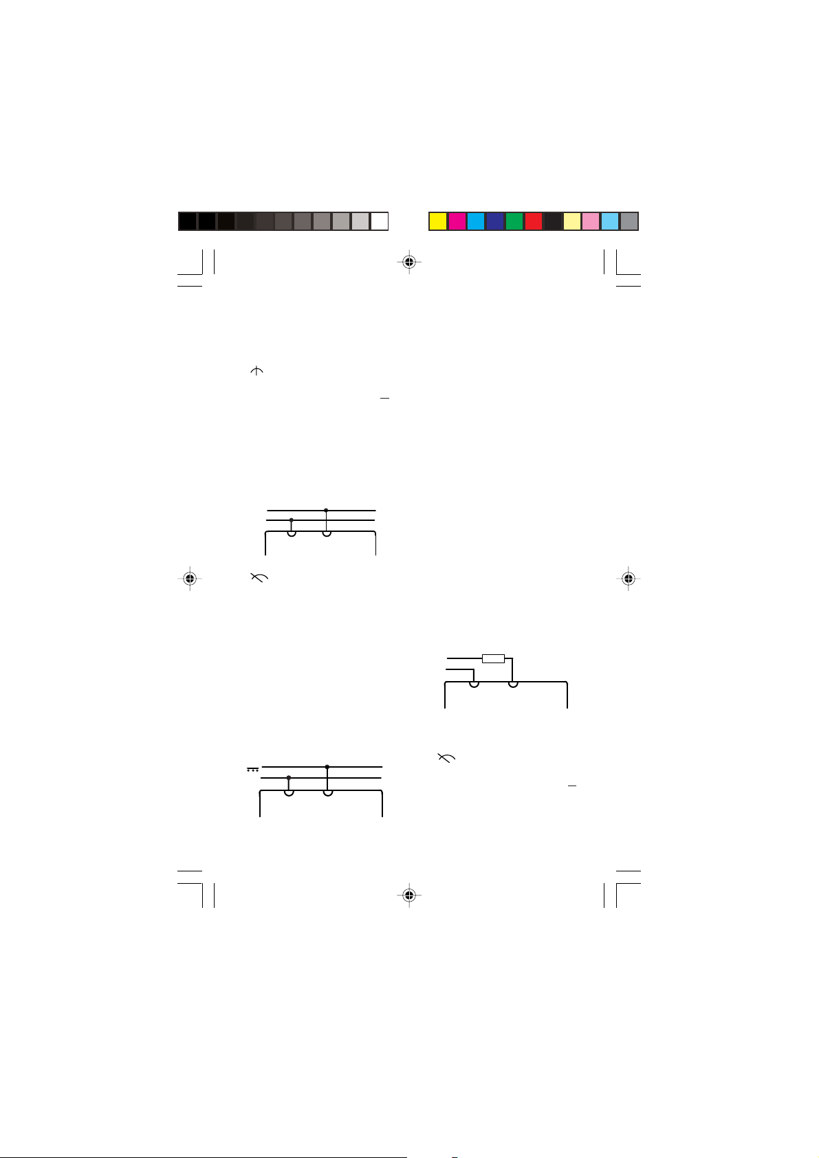
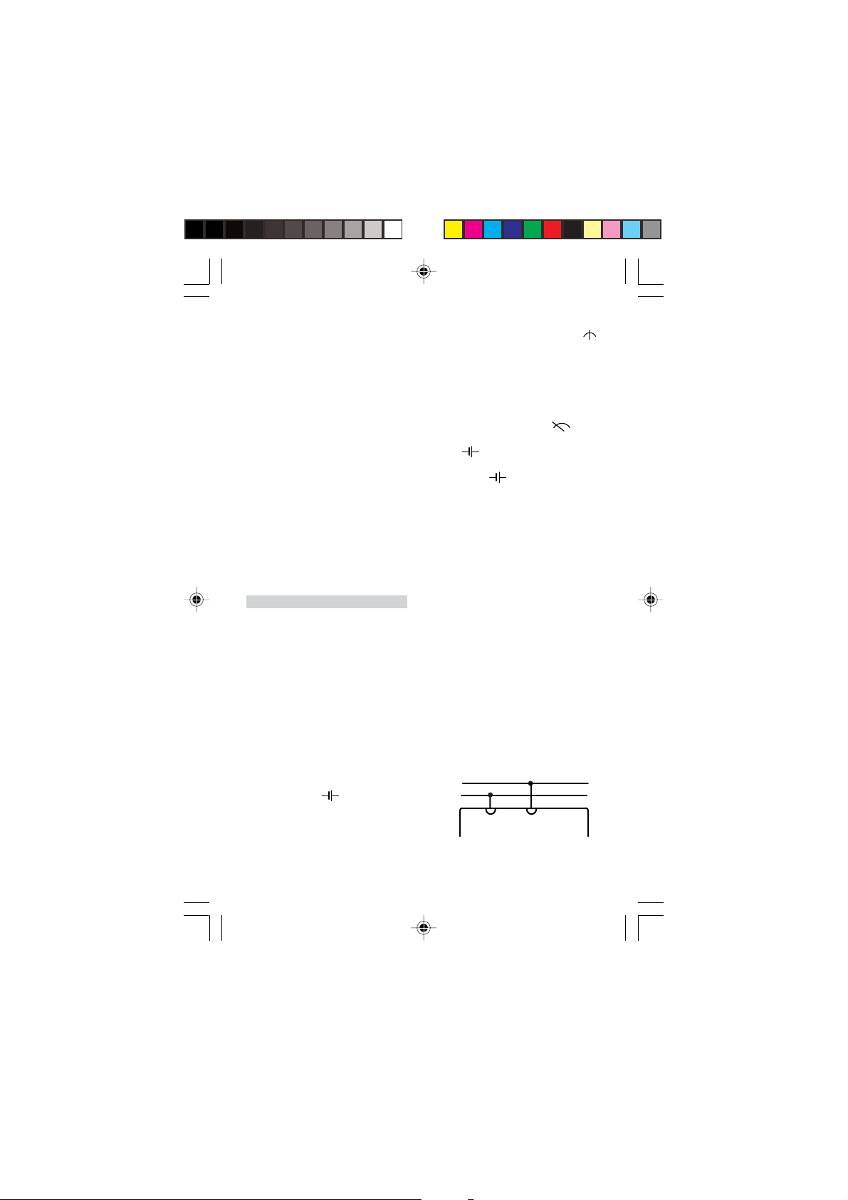
3.6 Strommessung
• Bei allen Strommessungen das
Multimeter in Reihe mit dem Verbraucher in die Leitung schalten,
die das geringste Potential gegen
Erde hat.
3.6.1 Gleichstrommessung, direkt
3.6.1.1 Betriebsart: Elektrischer
Nullpunkt links
• Schiebeschalter (4) in Position
„ ” bringen.
• Mittels Drehschalter (1) den ent-
sprechenden Messbereich „A ...”
auswählen.
• Multimeter anschließen und Wert
auf der oberen Skala ablesen.
4
Page 5
3.6.1.2 Betriebsart: Elektrischer
_
+
~
Nullpunkt Mitte
• Schiebeschalter (4) in Position
„ ” bringen.
• Mittels Drehschalter (1) den ent-
sprechenden Messbereich „A ...”
auswählen.
• Zeiger muss in Skalenmitte ste-
hen.
• Multimeter anschließen und Wert
auf der unteren Skala ablesen.
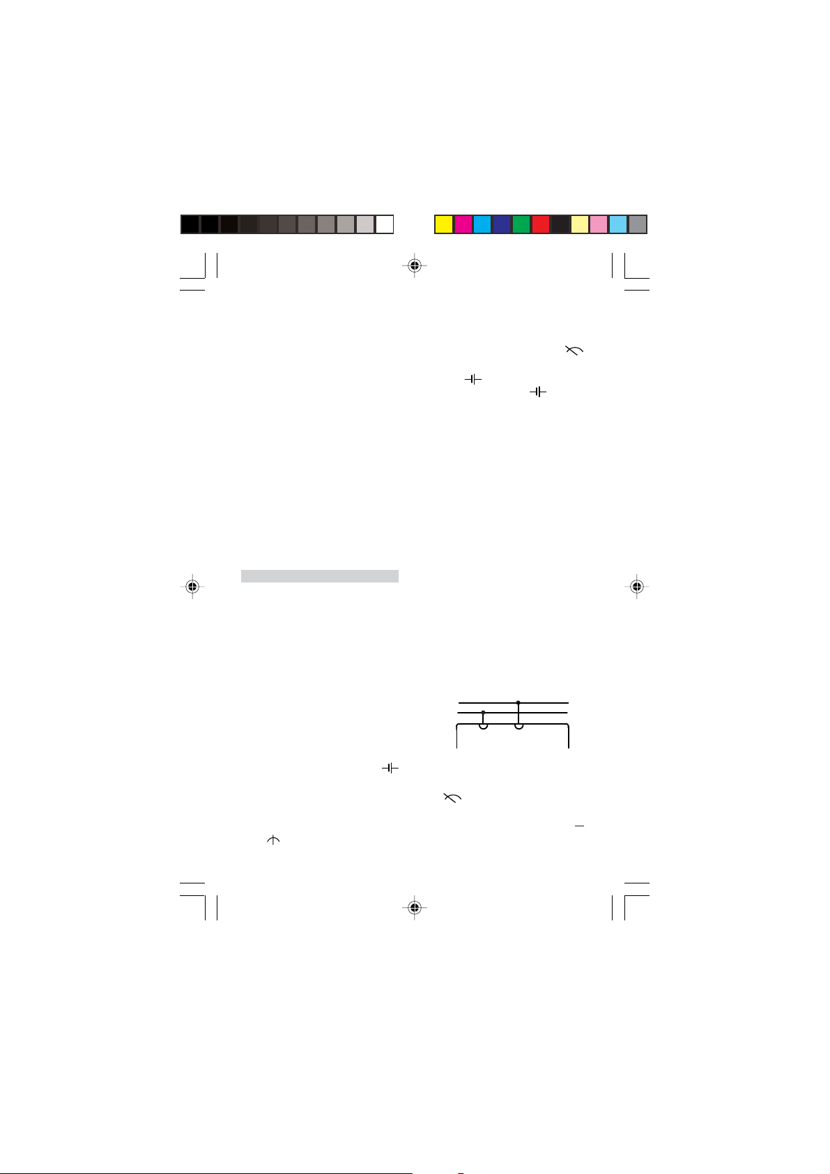
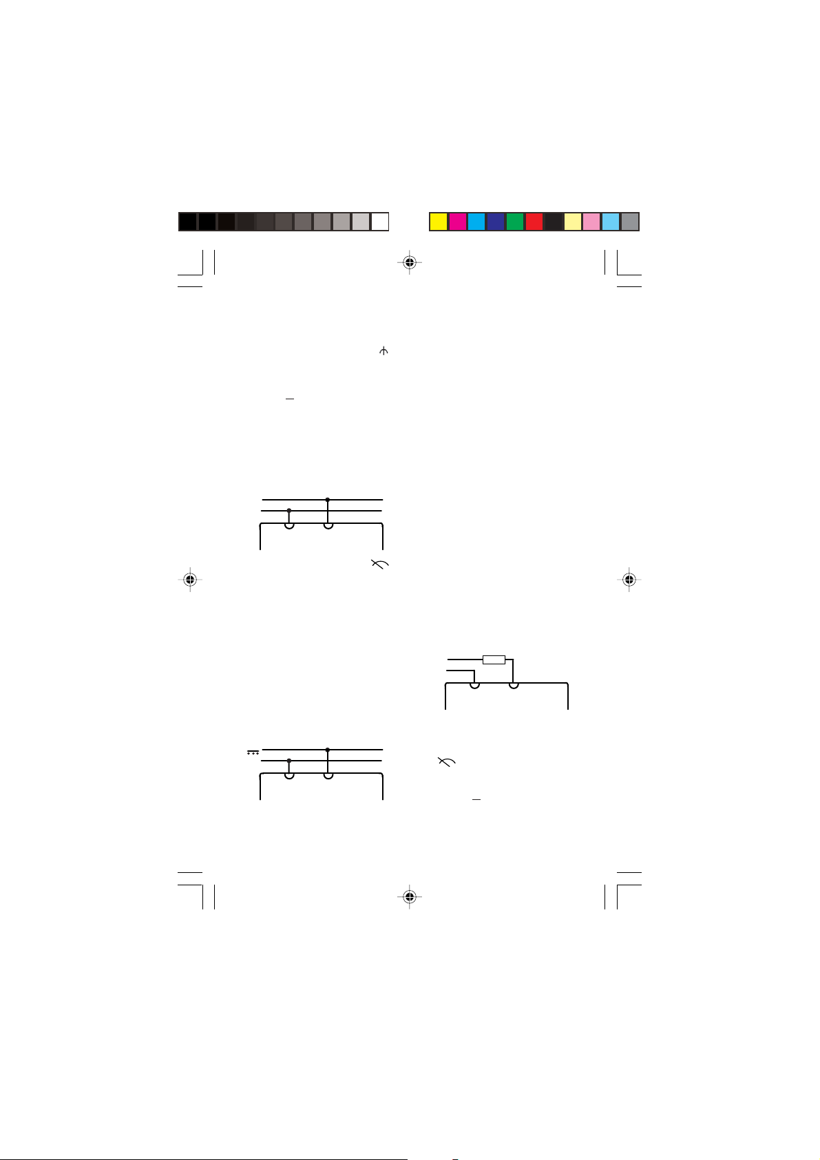
3.6.2 Gleichstrommessung über
Nebenwiderstände (Shunts)
3.6.2.1 Betriebsart: Nullpunkt links
• Schiebeschalter (4) in Position
„ ” bringen.
• Drehschalter (1) in die Position
„V ... 100 mV” stellen.
• Multimeter anschließen und Wert
auf oberer Skala ablesen.
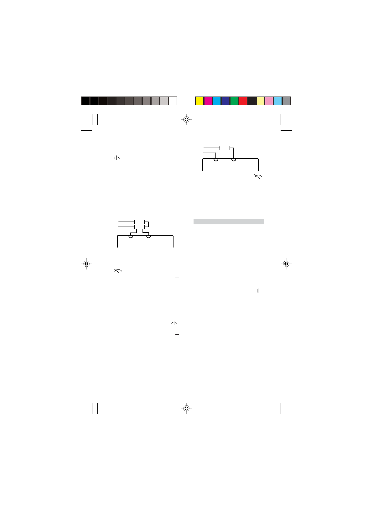
3.6.2.2 Betriebsart: Nullpunkt Mitte
• Schiebeschalter (4) in Position
„ ” bringen.
• Drehschalter (1) in die Position
„V ... 100 mV” stellen.
• Zeiger muss auf Skalenmitte zei-
gen.
• Multimeter anschließen und Wert
auf der unteren Skala ablesen.
3.6.3 Wechselstrommessung
• Schiebeschalter (4) in Position
„ ” bringen.
• Mittels Drehschalter (1) den ent-
sprechenden Messbereich „A~”
auswählen.
• Multimeter anschließen und Wert
auf der oberen Skala ablesen.
4 Wartung
4.1 Reinigung
• Das Multimeter nur mit einem
Pinsel oder weichem Tuch reinigen. Bei Auftreten von statischer
Aufladung des Sichtfensters kann
diese mit einem feuchtem Tuch
oder Antistatikmittel beseitigt werden.
4.2 Batteriewechsel
• Schlägt der Zeiger bei der Batte-
riekontrolle nicht mehr in das mit
„ ” gekennzeichnete Batterietestfeld aus, so ist die Batterie zu
wechseln (siehe 3.1).
4.3 Sicherungswechsel
• Das Multimeter ist mit einer
Schmelzsicherung F3,15/250 ausgestattet. Die Sicherungshalter
befinden sich auf der Platine. Zum
Wechseln der Sicherung Gerät wie
unter 3.1 beschrieben öffnen.
3B Scientific GmbH • Rudorffweg 8 • 21031 Hamburg • Deutschland • www.3bscientific.com • Technische Änderungen vorbehalten
5
Page 6
3B SCIENTIFIC3B SCIENTIFIC
3B SCIENTIFIC®
3B SCIENTIFIC3B SCIENTIFIC
PHYSICSPHYSICS
PHYSICS
PHYSICSPHYSICS
U17450 Analog Multimeter with Zero-point Center/Left
Instruction Sheet
10/04 MC/ALF
1 Rotar y switch to select the
3
4
2
1
measurement range
2 Rotary knob to set the
6
electrical zero-point in the
center of the scale
3 Safety connection sockets
5
4 Slide switch to select the
operating mode
5 Adjustment screw to set the
zero-point mechanically
6 Nub to latch the housing
shut
Handheld meter for current and
voltage measurement.
1. Safety instructions
• Before using the analog multime-
ter, make sure you read the operating instructions carefully and
that you comply with them completely.
• The safety of the multimeter and
the person operating it can only
be guaranteed if it is used in accordance with the instructions. Do
not operate or handle this unit
incorrectly or inappropriately.
• The device may only be used by
persons, who are aware of the hazards of contact (for voltages over
30 V rms) and can undertake the
appropriate safety precautions.
This also includes the appearance
of unforeseen voltages e.g. in defective units or charged capacitors.
• In the case of voltage and current
measurements the nominal voltage between the phase and neutral conductor may not exceed 300
V according to CAT II (in circuits
that are directly connected to the
mains) and CAT III (in building wiring installations) 300 V.
• The analog multimeter may be
used for measurements in circuits
with corona discharge (high voltage).
• In measurements involving RF cir-
cuits special care must be taken
due to the existence of dangerous
hybrid voltages.
• The appropriate permissible mea-
surement range may not be exceeded. Always change from a
higher measurement range to a
6
Page 7

lower measurement range.
• Before using the device, check the
housing and the measurement
cables for any damage.
• Do not conduct measurements in
a damp environment. Workplace,
hands, shoes and floor must be
dry.
• Before opening the housing all
measurement leads are disconnected from the device.
2. Description, technical data
Active analog multimeter with a
slide switch for selection of the operating mode and a rotary switch to
select the measurement range as
well as a scale with the mirrored
background for parallax-free readings with a zero-point adjustable to
the center or the left of the scale.
By adjusting the electrical zero-point
to the center of the scale bipolar DC
voltage and current measurements
can be conducted without worrying
about polarity. The device is extremely robust in terms of load capacity and is equipped with excellent overload protection due to its
two anti-parallel diodes as well as
moving coil movement which is not
sensitive to external electromagnetic fields. The safety connection sockets offer protection against accidental touch contact. After approx. 45
mins the battery is automatically
switched off. The power can be reestablished by turning off and on
using the slide switch for the operating mode. The robust plastic housing and the spring-connected bearing jewels of the movement guarantee protection against damage
caused by mechanical stress.
Measurement ranges:
Voltage measurement:
DC
Meas. range Internal resistance
100 mV 10 MΩ
300 mV 10 MΩ
1 V 10 MΩ
3 V 10 MΩ
10 V 10 MΩ
100 V 10 MΩ
300 V 10 MΩ
AC
Meas. range Internal resistance
3 V 1 MΩ
10 V 1 MΩ
30 V 1 MΩ
100 V 1 MΩ
300 V 1 MΩ
Current measurement AC/DC:
Meas. range Voltage drop
0.1 mA 55 mV
1 mA 55 mV
10 mA 55 mV
100 mA 55 mV
1 A 53 mV
3 A 51 mV
Accuracy: DC class 2; AC class 3
Effective variables and nominal operating ranges:
Temperature 0 – 40° C: ± 2% / K
Frequency for all measurement
ranges: ±2.5% at 30 Hz up to
1.5 kHz ± 5% at 1.5 kHz
up to 3 kHz
Reference conditions:
Ambient temperature: +23° C ± 2 K
Frequency: 50 to 60 Hz
Waveform: Sinusoidal
7
Page 8
Overload protection:
+
F3 fuse, 15 H/250 V in accordance
with DIN VDE 0820 Section 22/EN 60
127-2 as circuit protection in the
case of overload; movement protected by 2 antiparallel-connected diodes
Protection class:
IEC 1010-1/EN 61010-1/ VDE 0411-1
Overvoltage category: CAT III
Nominal voltage: 300 V
Degree of pollution: 2
Test voltage: 3.7 kV~
EMV: Electromagnetic compatibility
Jamming: EN 50081-1:1992
Interference
immunity: EN 50082-1:1992
Power supply: 1 x 9 V flat cell battery, IEC 6F22
Dimensions: 98 x 138 x 35 mm
Weight: approx. 0.3 kg
3. Operation
3.1 Readying for use
• Insert battery into the battery
compartment. To do this remove
the section of housing by pressing
in the nub (6), e.g. using a screwdriver. Then insert the battery and
connected it to the battery clip.
Replace the housing section and
snap it into place.
• Check the mechanical zero-point.
The measuring instrument may
not be connected at this time. Set
the sliding switch (4) to the “0”
position. The needle must be located in the “ OFF” position
when the multimeter is in a horizontal position. If necessary make
the corresponding adjustments
with the adjustment screw (5).
• Check the electrical zero-point. Set
the slide switch (4) into the “ ”
position. Select the measurement
range, the needle must be set to
zero-point in the center of the
scale, otherwise correct using the
rotary knob (2).
• Check the battery. To do this set
the slide switch (4) to “ ” , and
then adjust the rotary switch (1)
to“ ”. If the needle does not deflect into the battery test zone designated “ ” the battery must be
replaced.
3.2 General instructions
• When performing measurements
always set the rotary switch (1) to
the highest measurement range.
Then turn the switch to lower ranges until you obtain optimum needle deflection.
• When the power supply is inter-
rupted by the automatic battery
switch-off (after approx. 45 min.)
switch the slide switch (4) on and
off again.
• When the multimeter is not in use,
disconnect all measurement leads
from the meter, reset the rotary
switch (1) to the highest range, set
the slide switch (4) to the “0” setting and, if necessary, remove the
battery.
3.3 DC voltage measurement
_
8
Page 9
3.3.1 Operating mode: electrical
_
+
3.3.2 Operating mode: electrical
zero-point center
• Set the slide switch (4) to the “ ”
setting.
• Using the rotary switch (1) select
the corresponding measurement
range “V ...”.
• The needle should now be posi-
tioned in the center of the scale.
• Connect the multimeter and take
a reading from the lower scale.
3.4 Measuring alternating
voltage, directly up to 300 V
~
• Set the slide switch (4) to “ ”
setting.
• Using the rotary switch (1) select
the corresponding measurement
range “V~”.
• Connect the multimeter and take
a reading from the upper scale.
• To reduce the effects of the fre-
quency, connect the socket “
directly to ground or to the point
with the lowest potential with respect to ground.
3.5 Measuring AC voltage with
superimposed DC voltage
⊥⊥
⊥”
⊥⊥
~
• With the aid of a capacitor (recom-
mended: 4.7 µF/630 V) it is possi-
ble to isolate DC-voltage components in an amplifier output stage,
for example. The resultant measurement error is less than 0.2%
at a measurement frequency of
50 Hz.
• Proceed with the measurement as
stated in point 3.4.
• Measurement of the DC voltage
components is performed as described under 3.3.
• To avoid overloading, the set mea-
surement range must be greater
than the initially determined DC
voltage components.
• Caution: before switching to a low-
er measurement range both voltage components must be checked.
3.6 Current measurement
• When performing current mea-
surements the multimeter must
be connected in series with the
load in the circuit, which has the
lowest potential with respect to
ground.
3.6.1 DC measurement, directly
3.6.1.1 Operating mode: electrical
zero-point left
• Switch the slide switch (4) to the
“ ” setting.
• Using the rotary switch (1), select
the corresponding measurement
range “A ...”.
• Connect the multimeter take a
reading from the upper scale.
9
Page 10
3.6.1.2 Operating mode: electrical
_
+
~
zero-point center
• Adjust the slide switch (4) to the
“ ” setting.
• Using the rotary switch (1), select
the corresponding measurement
range “A ...”.
• The needle should be located in
the center of the scale.
• Connect the multimeter and take
a reading from the lower scale.
3.6.2 Measuring DC current using
shunts
3.6.2.1 Operating mode: Zero-point
left
• Set the slide switch (4) to the
“ ”.
• Set the rotary switch (1) to the “V ...
100 mV” setting.
• Connect the multimeter and the
take a reading from the upper
scale.
3.6.2.2 Operating mode: Zero-point
center
• Set the slide switch (4) to the “ ”
setting.
• Set the rotary switch (1) to the “V ...
100 mV” position.
• The needle should now point to
the center of the scale.
• Connect the multimeter and take
a reading from the lower scale.
3.6.3 Measuring AC current
• Set the slide switch (4) to the “ ”
setting.
• Use the rotary switch (1) to select
the corresponding measurement
range “A~”.
• Connect the multimeter and take
a reading from the upper scale.
4 Maintenance
4.1 Cleaning
• Only use a paintbrush or soft tow-
el to clean the multimeter. If static electrical charge builds up on
the view window, this can be eliminated using a damp rag or an antistatic agent.
4.2 Replacing the battery
• If during the battery test the nee-
dle no longer deflects to the battery test zone depicted with “ ”,
the battery must be replaced (see
3.1).
4.3 Replacing the fuse
• The multimeter is equipped with
a safety fuse F3,15/250. The fuse
holder is located on the printed
circuit board. To replace the fuse
the device must be opened as described in section 3.1.
3B Scientific GmbH • Rudorffweg 8 • 21031 Hamburg • Ger many • www.3bscientific.com • Technical amendments are possible
10
Page 11

3B SCIENTIFIC3B SCIENTIFIC
3B SCIENTIFIC®
3B SCIENTIFIC3B SCIENTIFIC
PHYSICSPHYSICS
PHYSICS
PHYSICSPHYSICS
U17450 Multimètre analogique point zéro centre/gauche
Manuel d’utilisation
10/04 MC/ALF
1 Sélecteur de la plage de
3
4
2
1
Appareil de mesure manuel pour la
mesure de courant et de tension.
1. Consignes de sécurité
• Avant d’utiliser le multimètre ana-
logique, lisez attentivement et intégralement le manuel d’utilisation et observez-le en tous points.
• Un emploi conforme garantit la
sécurité du multimètre et de son
utilisateur. Evitez toute manipulation incorrecte ou négligente de
l’appareil.
• Seules ont le droit d’utiliser cet
appareil des personnes sachant
reconnaître les dangers émanant
d’un contact (avec des tensions supérieures à une valeur effective de
30 V) et prendre les mesures de
sécurité appropriées. Parmi les
dangers, il faut également citer
l’apparition imprévue de tensions,
• Lors des mesures de tension et de
• Le multimètre analogique ne doit
• Lors de mesures dans des circuits
• La plage de mesure autorisée ne
mesure
2 Bouton pour le réglage du
6
point zéro électrique au
milieu de la graduation
3 Douilles de connexion de
5
sécurité
4 Sélecteur de la plage du
mode de service
5 Vis pour le réglage du point
zéro mécanique
6 Taquet de verrouillage du
boîtier
par ex. sur des appareils défectueux ou des condensateurs chargés.
courant d’après CAT II (dans des
circuits électriques qui sont directement reliés au secteur) et CAT III
(dans l’installation des bâtiments),
la tension nominale entre la phase et le conducteur neutre ne doit
pas dépasser 300 V.
pas être utilisé pour la mesure
dans des circuits électriques à décharge en effet corona (haute tension).
HF, une prudence particulière
s’impose en raison du risque de
tensions composées dangereuses.
doit pas être dépassée. Passez
d’une plage de mesure élevée à
11
Page 12

une plage inférieure.
• Avant d’employer l’appareil, véri-
fiez que le boîtier et les câbles de
mesure sont en bon état.
• N’effectuez pas de mesures dans
un environnement humide. Le
lieu de travail, les mains, les
chaussures et le sol doivent être
secs.
• Avant d’ouvrir le boîtier, séparez
les câbles de mesure de l’appareil.
2. Description,
caractéristiques techniques
Multimètre analogique actif avec interrupteur à coulisse pour le mode
de service et sélecteur des plages de
mesure, ainsi que graduation à miroir pour la lecture sans parallaxe et
le point zéro réglable de l’échelle
centre / gauche. Le réglage du point
zéro électrique au milieu de la graduation permet de réaliser des mesures bipolaires de tension continue
et de courant continu sans tenir
compte de la polarité. Supportant de
fortes charges, l’appareil dispose
d’une protection contre les surcharges grâce à deux diodes antiparallèles ainsi qu’un dispositif de mesure
magnéto-électrique insensible aux
champs parasites. Les douilles de
sécurité offrent une protection contre tout contact involontaire. La batterie est automatiquement désactivée après environ 45 minutes. Pour
rétablir l’alimentation électrique, il
suffit de mettre l’interrupteur à coulisse du mode de service hors, puis
de nouveau en circuit. Le boîtier robuste en plastique et les vis à pierre
à ressort du dispositif de mesure
magnéto-électrique garantissent
une protection contre les endommagements et les sollicitations mécaniques.
Plages de mesure :
Mesure de tension :
CC
Plage de mes. Résistance int.
100 mV 10 MΩ
300 mV 10 MΩ
1 V 10 MΩ
3 V 10 MΩ
10 V 10 MΩ
100 V 10 MΩ
300 V 10 MΩ
CA
Plage de mes. Résistance int.
3 V 1 MΩ
10 V 1 MΩ
30 V 1 MΩ
100 V 1 MΩ
300 V 1 MΩ
Mesure de tension CC/CA :
Meas. range Chute de tension
0,1 mA 55 mV
1 mA 55 mV
10 mA 55 mV
100 mA 55 mV
1 A 53 mV
3 A 51 mV
Précision : CC classe 2 ; CA classe 3
Grandeurs d’influence et plages de
service nominales :
Température 0 – 40° C: ± 2% / K
Fréquence pour toutes les plages
de mesure : ±2,5% pour 30 Hz à
1,5 kHz
± 5% pour 1,5 kHz à
3 kHz
12
Page 13

Conditions de référence :
+
Température ambiante : +23° C ± 2 K
Fréquence : 50 à 60 Hz
Forme de courbe : sinus
Protection contre les surcharges :
fusible F3, 15 H/250 V d’après DIN
VDE 0820 partie 22/EN 60 127-2
comme protection de circuit en cas
de surcharge ; dispositif de mesure
protégé par 2 diodes antiparallèles
Classe de protection :
IEC 1010-1/EN 61010-1/ VDE 0411-1
Catégorie de surtension : CAT III
Tension nominale : 300 V
Degré d’encrassement : 2
Tension de contrôle : 3,7 kV~
CEM : compatibilité
électromagnétique
Emission parasite : EN 50081-
1:1992
Résistance aux parasites :
EN 50082-1:1992
Alimentation : 1 x batterie cellule
plate 9 V, IEC 6F22
Dimensions: 98 x 138 x 35 mm
Masse : approx. 0,3 kg
3. Manipulation
3.1 Mise en service
• Insérez la batterie dans son com-
partiment. Pour cela, retirez le
boîtier en pressant le taquet (6)
vers l’intérieur, par ex. au moyen
d’un tournevis. Puis, insérez la
batterie et reliez-la au clip. Replacez le boîtier.
• Contrôlez le point zéro mécanique.
L’appareil de mesure n’a pas encore le droit d’être connecté. Réglez l’interrupteur à coulisse (4) en
position « 0 ». Lorsque le multimètre est en position horizontale,
l’aiguille doit se trouver sur «
OFF ». Le cas échéant, ajustez-le
avec la vis de réglage (5).
• Contrôlez le point zéro électrique.
Réglez l’interrupteur à coulisse (4)
en position « ». Sélectionnez la
plage de mesure. L’aiguille doit se
trouver sur le point zéro au centre
de la graduation, sinon corrigezla avec le bouton (2).
• Contrôlez la batterie. Pour cela, ré-
glez l’interrupteur à coulisse (4) en
position « » et le bouton (1)
sur « ». Si l’aiguille ne dévie
pas dans le champ de contrôle
marqué de « », remplacez la
batterie.
3.2 Remarques générales
• Si vous effectuez des mesures avec
le sélecteur (1), réglez toujours la
plage de mesure maximale. Puis,
tournez le sélecteur vers les plages inférieures, jusqu’à ce que
vous obteniez une parfaite déviation de l’aiguille.
• Si l’alimentation est interrompue
par une mise hors service automatique (après environ 45 min), remettez l’interrupteur à coulisse (4)
hors, puis de nouveau en circuit.
• Si vous n’utilisez pas le multimè-
tre, retirez tous les câbles de mesure de l’appareil, remettez le sélecteur (1) sur la plage maximale,
réglez l’interrupteur (4) sur « 0 »,
le cas échéant, remplacez la batterie.
3.3 Mesure de tension continue
_
13
Page 14

3.3.1 Mode de service : Point zéro
_
+
électrique gauche
• Réglez l’interrupteur à coulisse (4)
en position « ».
• Avec le sélecteur (1), choisissez la
plage de mesure « V... ».
• Branchez le multimètre et lisez la
valeur sur la graduation du haut.
3.3.2 Mode de service : Point zéro
électrique centre
• Réglez l’interrupteur à coulisse (4)
en position « ».
• Avec le sélecteur (1), choisissez la
plage de mesure « V ... ».
• L’aiguille doit se trouver au centre
de la graduation.
• Branchez le multimètre et lisez la
valeur sur la graduation du bas.
3.4 Mesure de tension alternative,
directement jusqu’à 300 V
~
• Réglez l’interrupteur à coulisse (4)
en position « ».
• Avec le sélecteur (1), choisissez la
plage de mesure « V~ ».
• Branchez le multimètre et lisez la
valeur sur la graduation du haut.
• Pour réduire l’influence de la fré-
quence, reliez la douille «
rectement au potentiel de terre ou
au point le plus bas contre le potentiel de terre.
⊥⊥
⊥ » di-
⊥⊥
3.5 Mesure de la tension
alternative avec une tension
continue superposée
~
• A l’aide d’un condensateur (recom-
mandé : 4,7 µF/630 V),vous pouvez séparer les composantes d’une
tension continue apparaissant par
ex. à l’étage final d’une amplification. L’erreur de mesure est inférieure à 0,2 % avec une fréquence
de mesure de 50 Hz.
• Effectuez la mesure comme décrit
au point 3.4.
• Effectuez la mesure des compo-
santes de la tension continue comme décrit au point 3.3.
• Pour éviter une surcharge, la pla-
ge de mesure réglée doit être supérieure à la première composante de tension continue déterminée.
• Attention : avant de passer à une
plage de mesure inférieure, vérifiez les deux composantes de tension.
3.6 Mesure de courant
• Lors de toutes les mesures de cou-
rant, montez le multimètre en série avec le consommateur de la ligne qui présente le plus faible
potentiel contre la terre.
3.6.1 Mesure de courant continu
directe
14
Page 15

3.6.1.1 Mode de service : Point zéro
_
+
~
électrique gauche
• Réglez l’interrupteur à coulisse (4)
en position « ».
• Avec le sélecteur (1), choisissez la
plage de mesure « A ... ».
• Branchez le multimètre et lisez la
valeur sur la graduation du haut.
3.6.1.2 Mode de service : Point zéro
électrique centre
• Réglez l’interrupteur à coulisse (4)
en position « ».
• Avec le sélecteur (1), choisissez la
plage de mesure «A ... ».
• L’aiguille doit se trouver au centre
de la graduation.
• Branchez le multimètre et lisez la
valeur sur la graduation du bas.
3.6.2 Mesure de courant continu
via des résistances en shunts
3.6.2.1 Mode de service : Point zéro
gauche
• Réglez l’interrupteur à coulisse (4)
en position « ».
• Réglez le sélecteur (1) en position
« V ... 100 mV ».
• Branchez le multimètre et lisez la
valeur sur la graduation du haut.
3.6.2.2 Mode de service : Point zéro
centre
• Réglez l’interrupteur à coulisse (4)
en position « ».
• Réglez le sélecteur (1) en position
« V ... 100 mV ».
• L’aiguille doit se trouver au centre
de la graduation.
• Branchez le multimètre et lisez la
valeur sur la graduation du bas.
3.6.3 Mesure de courant alternatif
• Réglez l’interrupteur à coulisse (4)
en position « ».
• Avec le sélecteur (1), choisissez la
plage de mesure « A~ ».
• Branchez le multimètre et lisez la
valeur sur la graduation du haut.
4 Entretien
4.1 Nettoyage
• Nettoyez le multimètre unique-
ment avec un pinceau ou un chiffon doux. Eliminez une éventuelle charge statique sur la fenêtreregard à l’aide d’un chiffon humide ou d’un agent antistatique.
4.2 Changement de batterie
• Si l’aiguille ne dévie plus dans la
plage de test « » lors du contrôle de batterie, remplacez celleci (cf. 3.1).
4.3 Changement de fusible
• Le multimètre est équipé d’un fu-
sible F3,15/250. Le porte-fusible se
trouve sur la platine. Pour remplacer le fusible, ouvrez le boîtier
comme décrit au point 3.1.
3B Scientific GmbH•Rudorffweg 8•21031 Hamburg•Allemagne•www.3bscientific.com•Sous réserve de modifications techniques
15
Page 16

3B SCIENTIFIC3B SCIENTIFIC
3B SCIENTIFIC®
3B SCIENTIFIC3B SCIENTIFIC
PHYSICSPHYSICS
PHYSICS
PHYSICSPHYSICS
U17450 Multimetro analogico zero centro/sinistra
Istruzioni per l’uso
10/04 MC/ALF
3
4
2
1
Misuratore manuale per la misurazione di corrente e tensione.
1. Avvertenze per la sicurezza
• Prima di utilizzare il multimetro
analogico, leggere accuratamente
l’intero manuale di istruzioni e seguire tutti i punti riportati.
• La sicurezza del multimetro e del-
l’utente sono garantite solo se l’apparecchio viene utilizzato per lo
scopo previsto dal produttore. Non
maneggiare l’apparecchio impropriamente o incautamente.
• L’apparecchio deve essere utilizza-
to esclusivamente da persone in
grado di riconoscere i pericoli di
folgorazione (a tensioni superiori
al valore di picco di 30 V) e di adottare misure di sicurezza corrispondenti. Tra questi pericoli possono
1 Interruttore rotante per la
2 Manopola per la regolazione
6
3 Jack di raccordo di sicurezza
5
4 Interruttore a scorrimento
5 Vite di registro per la
6 Sporgenza per il bloccaggio
essere elencati anche picchi di tensione imprevisti, causati ad es. da
apparecchi difettosi o condensatori carichi.
• Durante le misurazioni di tensio-
ne e corrente, la tensione nominale tra fase e conduttore neutro
secondo CAT II (in circuiti elettrici
collegati direttamente alla rete) e
CAT III (in installazioni di edifici)
non deve superare 300 V.
• Non utilizzare il multimetro ana-
logico per misurazioni in circuiti
elettrici con effetto corona (alta
tensione).
• Durante le misurazioni in circuiti
elettrici ad alta frequenza, operare con particolare cautela a causa
dell’eventuale presenza di tensioni miste pericolose.
• Non superare il range di misura
consentito. Passare da un range di
selezione del range di misura
elettrica del punto zero a
centro scala
per la selezione della
modalità operativa
regolazione meccanica del
punto zero
dell’alloggiamento
16
Page 17

misura elevato ad uno più basso.
• Prima dell’utilizzo dell’apparec-
chio, verificare l’assenza di danni
all’alloggiamento e alle linee di
misura.
• Non effettuare misurazioni in
ambienti umidi. Assicurarsi che
luogo di lavoro, mani, scarpe e pavimento siano asciutti.
• Prima di aprire l’alloggiamento,
scollegare le linee di misura dall’apparecchio.
2. Descrizione, dati tecnici
Multimetro analogico attivo con un
interruttore a scorrimento per la
selezione della modalità operativa
e un interruttore rotante per la selezione del range di misura, nonché
scala a specchio per lettura priva di
parallasse e punto zero centro/sinistra della scala regolabile. La regolazione del punto zero elettrico a
centro scala consente di misurare
tensioni e correnti continue bipolari a prescindere dalla polarità. L’apparecchio è provvisto di ottima protezione da sovraccarico fornita da
due diodi contrapposti nonché di
uno strumento a bobina mobile insensibile ai campi esterni. I jack di
raccordo di sicurezza offrono protezione da contatti involontari. Dopo
ca. 45 minuti, l’apparecchio disattiva automaticamente la batteria. Per
ripristinare l’alimentazione di corrente, disattivare e attivare l’interruttore a scorrimento della modalità operativa. Il robusto alloggiamento in plastica e il supporto ammortizzante dello strumento a bobina
mobile garantiscono una protezione ottimale dai danni e dalle sollecitazioni meccaniche.
Range di misura:
Misurazione della tensione:
CC
Range di mis. Resistenza int.
100 mV 10 MΩ
300 mV 10 MΩ
1 V 10 MΩ
3 V 10 MΩ
10 V 10 MΩ
100 V 10 MΩ
300 V 10 MΩ
CA
Range di mis. Resistenza int.
3 V 1 MΩ
10 V 1 MΩ
30 V 1 MΩ
100 V 1 MΩ
300 V 1 MΩ
Misurazione della corrente CA/CC:
Range di mis. Caduta di tens.
0,1 mA 55 mV
1 mA 55 mV
10 mA 55 mV
100 mA 55 mV
1 A 53 mV
3 A 51 mV
Precisione: CC classe 2; CA classe 3
Fattori di influenza e campi d’impiego nominali:
Temperatura 0 – 40 °C: ± 2% / K
Frequenza per tutti i range di
misura:± 2,5% da 30 Hz a 1,5 kHz
± 5% da 1,5 kHz a 3 kHz
Condizioni di riferimento:
Temperatura ambiente: + 23 °C ± 2 K
Frequenza: da 50 a 60 Hz
Forma d’onda: sinusoidale
Protezione da sovraccarico: fusibile
F3, 15 H/250 V secondo DIN VDE
0820, parte 22/EN 60 127-2 come
17
Page 18

protezione del circuito elettrico da
+
sovraccarico; strumento di misura
protetto con 2 diodi contrapposti
Classe di protezione:
IEC 1010-1/EN 61010-1/ VDE 0411-1
Categoria di sovratensione: CAT III
Tensione nominale : 300 V
Grado di inquinamento: 2
Tensione di prova: 3,7 kV~
EMV: compatibilità elettromagnetica
Emissione di interferenze:
EN 50081-1:1992
Immunità ai disturbi:
EN 50082-1:1992
Alimentazione elettrica: 1 batteria
a celle piatte da 9 V, IEC 6F22
Dimensioni: 98 x 138 x 35 mm
Peso: ca. 0,3 kg
3. Utilizzo
3.1 Messa in funzione
• Inserire la batteria nell’apposito
vano. A tale scopo, rimuovere il
coperchio dell’alloggiamento premendo la sporgenza (6) verso l’interno, ad es. con un cacciavite.
Quindi inserire la batteria e collegarla al connettore rispettivo. Ricollocare il coperchio dell’alloggiamento in posizione e farlo scattare in sede.
• Controllare il punto zero meccani-
co. Per fare ciò, assicurarsi che il
misuratore non sia collegato. Portare l’interruttore a scorrimento (4)
nella posizione “0”. Con il multimetro in posizione orizzontale,
l’indicatore deve trovarsi su “
OFF”. Eventualmente, regolare con
la vite di registro (5).
• Controllare il punto zero elettrico.
Portare l’interruttore a scorrimento (4) nella posizione “ ”. Sele-
zionare il range di misura, l’indicatore deve trovarsi sul punto zero
a centro scala. In caso contrario
correggere con la manopola (2).
• Controllo della batteria. A tale sco-
po portare l’interruttore a scorrimento (4) nella posizione “ ”,
girare l’interruttore rotante (1) sulla posizione “ ”. Se l’indicatore
non devia sul campo di prova della batteria contrassegnato dal simbolo “ ”, sostituire la batteria.
3.2 Indicazioni generali
• Durante le misurazioni, portare
sempre l’interruttore rotante (1)
sul range di misura più elevato.
Quindi, ruotarlo verso range inferiori fino ad ottenere una deviazione ottimale dell’indicatore.
• In caso di interruzione dell’ali-
mentazione per spegnimento automatico (dopo ca. 45 min.), disattivare e riattivare l’interruttore a
scorrimento (4).
• In caso di mancato utilizzo del
multimetro, scollegare tutte le linee di misura dal misuratore, riportare l’interruttore rotante (1)
sul range più elevato, portare l’interruttore a scorrimento (4) nella
posizione “0” ed eventualmente
rimuovere la batteria.
3.3 Misurazione di tensione
continua
_
3.3.1 Modalità operativa: punto zero
elettrico sinistra
18
Page 19

• Portare l’interruttore a scorrimen-
_
+
to (4) nella posizione “ ”.
• Con l’interruttore rotante (1) sele-
zionare il range di misura corrispondente “V...”.
• Collegare il multimetro e leggere
il valore sulla scala superiore.
3.5 Misurazione della tensione
alternata con tensione
continua sovrapposta
~
3.3.2 Modalità operativa: punto zero
elettrico centro
• Portare l’interruttore a scorrimen-
to (4) nella posizione “ ”.
• Con l’interruttore rotante (1) sele-
zionare il range di misura corrispondente “V ... ”.
• L’indicatore deve trovarsi a centro
scala.
• Collegare il multimetro e leggere
il valore sulla scala inferiore.
3.4 Misurazione diretta di tensione
alternata, fino a 300 V
~
• Portare l’interruttore a scorrimen-
to (4) nella posizione “ ”.
• Con l’interruttore rotante (1) sele-
zionare il range di misura corrispondente “V~”.
• Collegare il multimetro e leggere
il valore sulla scala superiore.
• Per ridurre i disturbi di frequen-
za, collegare il jack di raccordo “
direttamente al conduttore di terra o al punto più basso rispetto al
conduttore di terra.
⊥⊥
⊥”
⊥⊥
• Con l’ausilio di un condensatore
(consigliato: 4,7 µF/630 V) è possibile separare i componenti che
operano in tensione continua ad
es. in uno stadio finale di amplificazione. L’errore di misurazione
risultante è inferiore allo 0,2% con
una frequenza di misura di 50 Hz.
• Per la misurazione, procedere
come descritto al punto 3.4.
• Per la misurazione di componenti
a tensione continua, procedere
come descritto al punto 3.3.
• Per evitare sovraccarichi, il range
di misura impostato deve essere
maggiore del componente in tensione continua rilevato per primo.
• Attenzione: prima di commutare
ad un range di misura inferiore,
controllare i due componenti sotto tensione.
3.6 Misurazione di corrente
• Durante le misurazioni di corren-
te, collegare il multimetro in serie con l’utenza nella linea che
presenta il potenziale a terra più
ridotto.
3.6.1 Modalità operativa: punto
zero elettrico sinistra
19
Page 20

3.6.1.1 Modalità operativa: punto
_
+
~
zero elettrico sinistra
• Portare l’interruttore a scorrimen-
to (4) nella posizione “ .
• L’indicatore deve trovarsi a centro
scala.
• Collegare il multimetro e leggere
il valore sulla scala inferiore.
• Con l’interruttore rotante (1) sele-
zionare il range di misura corrispondente “A ... ».
3.6.3 Misurazione di corrente al-
ternata
• Collegare il multimetro e leggere
il valore sulla scala inferiore.
3.6.1.2 Modalità operativa: punto
zero elettrico centro
• Portare l’interruttore a scorrimen-
to (4) nella posizione “ ”.
• Con l’interruttore rotante (1) sele-
zionare il range di misura corrispondente “A ... “.
• L’indicatore deve trovarsi a centro
scala.
• Collegare il multimetro e leggere
il valore sulla scala inferiore.
3.6.2 Misurazione di corrente continua mediante derivatori (shunt)
• Portare l’interruttore a scorrimen-
to (4) nella posizione “ ”.
• Con l’interruttore rotante (1) sele-
zionare il range di misura corrispondente “A~”.
• Collegare il multimetro e leggere
il valore sulla scala superiore.
4 Manutenzione
4.1 Pulizia
• Pulire il multimetro esclusivamen-
te con un pennello o con un panno morbido. In caso di accumulo
di elettricità statica nella finestra
di ispezione, eliminare la carica
con un panno inumidito o con un
3.6.2.1 Modalità operativa: punto
zero sinistra
• Portare l’interruttore a scorrimen-
to (4) nella posizione “ ”.
• Portare l’interruttore rotante (1)
nella posizione “V ... 100 mV”.
• Collegare il multimetro e leggere
il valore sulla scala superiore.
3.6.2.2 Modalità operativa: punto
zero centro
• Portare l’interruttore a scorrimen-
to (4) nella posizione “ ”.
• Portare l’interruttore rotante (1)
nella posizione “V ... 100 mV”.
3B Scientific GmbH • Rudorffweg 8 • 21031 Hamburg • Germ ania • www.3bscientific.com • Con riserva di modifiche tecniche
detergente antistatico.
4.2 Sostituzione della batteria
• Se durante il controllo della bat-
teria l’indicatore non devia più nel
campo contrassegnato dal simbolo “ ”, sostituire la batteria (vedere 3.1).
s
4.3 Sostituzione del fusibile
• Il multimetro è dotato di una val-
vola a fusibile F3,15/250. I portafusibili sono situati sulla scheda.
Per sostituire il fusibile, aprire l’apparecchio come descritto al punto 3.1.
20
Page 21

3B SCIENTIFIC3B SCIENTIFIC
3B SCIENTIFIC®
3B SCIENTIFIC3B SCIENTIFIC
PHYSICSPHYSICS
PHYSICS
PHYSICSPHYSICS
U17450 Multímetro analógico con punto cero al centro/izquierda
Instrucciones de servicio
10/04 MC/ALF
4
3
2
1
1 Conmutador giratorio para
selección del rango de
medición
2 Botón giratorio para el ajuste
6
eléctrico del punto cero en el
centro de la escala
3 Clavijeros de conexión de
5
seguridad
4 Conmutador deslizante para
selección del modo de
servicio
5 Tornillo para ajuste
mecánico del punto cero
6 Botón para enclave de la caja
Instrumento de medición manual
de corriente y tensión.
1. Aviso de seguridad
• Antes del empleo del multímetro
analógico se deben leer cuidadosa y completamente las instrucciones de uso y se deben observar
todas sus indicaciones.
• Un empleo adecuado a lo deter-
minado garantiza la seguridad del
multímetro y de quien lo utiliza.
El equipo no se debe tratar de
manera incorrecta o descuidada.
• El equipo sólo debe ser usado por
personas que reconozcan los peligros de contacto (con tensiones
mayores a 30 V de valor eficaz) y
que puedan implementar las correspondientes medidas de seguridad. Entre los peligros se cuenta
la aparición de tensiones no esperadas, por ejemplo, en el caso de
equipos defectuosos o de condensadores bajo carga.
• La tensión nominal entre fase y
conductor neutro no debe sobrepasar los 300 V, para mediciones
de tensión y de corriente, según
CAT II (en circuitos de corriente
que no se encuentren conectados
directamente con la red) y CAT III
(en las instalaciones de edificios).
• El multímetro analógico no se
debe emplear para mediciones en
circuitos de corriente con descargas de corona (alta tensión).
• Debe ponerse especial cuidado
durante las mediciones de circuitos de corriente de alta frecuencia, puesto que en este caso se encuentran presentes las peligrosas
tensiones mixtas.
21
Page 22

• No se debe sobrepasar el rango de
medición permitido. Conmutar de
un rango más alto de medición a
uno más pequeño.
• Antes de emplear el equipo se
debe revisar la caja y los cables de
medición en previsión de daños.
• No se debe realizar ninguna me-
dición en un entorno húmedo. El
sitio de trabajo, las manos, zapatos y el suelo deben estar secos.
• Antes de abrir la caja se deben se-
parar los cables de medición del
equipo.
2. Descripción, datos técnicos
Multímetro analógico activo con un
conmutador deslizante, para el
modo de operación, y un conmutador giratorio, para la selección del
rango de medición, así como con
una escala de base especular para
lectura libre de paralaje, y un escala con punto cero ajustable al centro y a la izquierda. Por medio del
ajuste del punto cero eléctrico, en
el centro de la escala, se pueden llevar a cabo mediciones de tensión
continua y de corriente continua
despreciando la polaridad. El equipo soporta altas carga y dispone de
una excelente protección contra sobrecargas por medio de dos diodos
antiparalelos, así como de un sistema de medida de cuadro móvil insensible a los campos externos. Los
clavijeros de conexión de seguridad
brindan protección contra un eventual contacto. Después de aprox. 45
minutos, la batería se desconecta
automáticamente. La reposición de
la alimentación de corriente se rea-
liza conmutando a “Off” y a “On” el
conmutador deslizante de modo de
operación. La robusta caja de plástico y las piedras de cojinete con
muelles del sistema de medición de
bobina móvil aseguran protección
contra daños y contra esfuerzos mecánicos.
Rangos de medida:
Medición de tensión:
DC
Rango de med. Resistencia int.
100 mV 10 MΩ
300 mV 10 MΩ
1 V 10 MΩ
3 V 10 MΩ
10 V 10 MΩ
100 V 10 MΩ
300 V 10 MΩ
CA
Rango de med. Resistencia int.
3 V 1 MΩ
10 V 1 MΩ
30 V 1 MΩ
100 V 1 MΩ
300 V 1 MΩ
Medición de corriente AC/DC:
Rango de med. Caída de tensión
0,1 mA 55 mV
1 mA 55 mV
10 mA 55 mV
100 mA 55 mV
1 A 53 mV
3 A 51 mV
Precisión: DC clase 2; AC clase 3
Magnitudes de influencia y rangos
de consumo nominal:
Temperatura 0 – 40° C: ± 2% / K
22
Page 23

Frecuencia para todos los rangos de
medida: ± 2,5% para 30 Hz
hasta 1,5 kHz
± 5% para 1,5 kHz
hasta 3 kHz
Condiciones de referencia:
Temp. ambiente: + 23° C ± 2 K
Frecuencia: 50 a 60 Hz
Forma de las curvas: sinusoidal
Protección contra sobrecarga:
Fusible F3, 15 H/250 V según DIN
VDE 0820 Parte 22/EN 60 127-2,
como protección de circuito de corriente contra sobrecargas; medidor
protegido con dos diodos conectados antiparalelamente
Clase de protección:
IEC 1010-1/EN 61010-1/VDE 0411-1
Categoría de sobretensión: CAT III
Tensión nominal: 300 V
Grado de polución: 2
Tensión de prueba: 3,7 kV~
EMV: resistencia a las perturbaciones electromagnéticas
Emisión de perturbaciones:
EN 50081-1:1992
Resistencia a las perturbaciones:
EN 50082-1:1992
Alimentación de corriente:
1 x 9 V pila de célula plana, IEC 6F22
Dimensiones: 98x138x35 mm
Peso: aprox. 0,3 kg
3. Servicio
3.1 Puesta en servicio
• Colocar la pila en el compartimen-
to respectivo. Para ello, retirar la
caja, presionando el botón (6) hacia adentro, por ejemplo, con un
destornillador. A continuación, insertar la pila y conectarla con el
clip de batería. Volver a colocar la
caja y enclavar el botón.
• Controlar el punto cero mecánico.
Durante este paso, el equipo de
medición no debe estar conectado. Llevar el conmutador deslizante (4) a la posición “0”. El indicador debe encontrarse en la posición “ OFF” si el multímetro
descansa horizontalmente. Dado
el caso, se debe realizar un ajuste
con el tornillo de regulación (5).
• Controlar el punto cero eléctrico.
Llevar el conmutador deslizante
(4) a la posición “ ”. Seleccionar
el rango de medición; el indicador debe encontrarse en el punto
cero del centro de la escala; si esto
no es así, se debe corregir dicha
posición con el botón giratorio (2).
• Control de la pila. Para este con-
trol, llevar el conmutador deslizante (4) a la posición “ ”, colocar el conmutador giratorio (1)
en la posición “ ”. Si el indicador no llega al campo de comprobación de la batería, rotulado con
“ ”, se debe llevar a cabo un
recambio de pila.
3.2 Notas generales
• Durante las mediciones siempre se
debe ajustar el conmutador giratorio (1) al más alto nivel de medida. A continuación, se debe bajar el rango hasta que se alcance
el tope óptimo del indicador.
• Tras la interrupción de la alimen-
tación de corriente, producida por
la desconexión automática de la
pila (después de aprox. 45 min), el
conmutador deslizante (4) se debe
llevar nuevamente a “OFF” y a
“ON” .
• Cuando el multímetro se encuen-
tre fuera de uso, se deben retirar
todos los cables de medición del
23
Page 24

equipo, el conmutador giratorio (1)
+
se debe volver a posicionar en el
más alto rango, el conmutador
deslizante (4) se debe llevar a la
posición “0” y, dado el caso, retirar la pila.
3.3 Medición de tensión continua
_
3.3.1 Modo de operación: Punto cero
eléctrico a la izquierda
• Llevar el conmutador deslizante
(4) a la posición “ ”.
• Por medio del conmutador girato-
rio (1), seleccionar el correspondiente rango de medida “V...”.
• Conectar el multímetro y leer el
valor en la escala superior.
3.3.2 Modo de operación: Punto cero
eléctrico en el centro
• Llevar el conmutador deslizante
(4) a la posición “ ”.
• Por medio del conmutador girato-
rio (1), seleccionar el correspondiente rango de medida “V ... ”.
• El indicador debe encontrarse en
la mitad de la escala.
• Conectar el multímetro y leer el
valor en la escala inferior.
3.4 Medición directa de tensión
continua, hasta 300 V
~
• Llevar el conmutador deslizante
(4) a la posición “ ”.
• Por medio del conmutador girato-
rio (1), seleccionar el correspondiente rango de medida “V~”.
• Conectar el multímetro y leer el
valor en la escala superior.
• Para disminuir la influencia de la
frecuencia, se conecta el clavijero
de conexión “
el potencial de tierra o con el punto más bajo en relación al potencial de tierra.
3.5 Medición de la tensión
alterna con tensión alterna
superpuesta
⊥⊥
⊥” directamente con
⊥⊥
~
• Con ayuda de un condensador (se
recomienda: 4,7 µF/630 V) se puede aislar la componente de tensión continua proveniente, por
ejemplo, de una etapa final de
amplificación. El error de medida
originado se encuentra por debajo de 0,2%, con una frecuencia de
medición de 50 Hz.
• La medición se realiza como se
describió en 3.4.
• La medición de la componente de
tensión continua se realiza como
se describió en 3.3.
• Para evitar sobrecargas, el rango
de medición ajustado debe ser
mayor que la componente de tensión continua determinada primeramente.
24
Page 25

• Atención: Antes de conmutar a un
_
+
_
+
~
rango de medición más bajo se
deben comprobar ambas componentes de tensión.
3.6 Medición de corriente
• Para todas las mediciones de co-
rriente, el multímetro se debe conectar en serie con la carga en el
conductor que tenga el menor
potencial de tierra.
3.6.1 Medición directa de corriente continua
3.6.1.1 Modo de operación: Punto
cero eléctrico a la izquierda
• Llevar el conmutador deslizante
(4) a la posición “ ”.
• Por medio del conmutador girato-
rio (1), seleccionar el correspondiente rango de medida “A ... ».
• Conectar el multímetro y leer el
valor en la escala superior.
3.6.1.2 Modo de operación: Punto
eléctrico cero en el centro
• Llevar el conmutador deslizante
(4) a la posición “ ”.
• Por medio del conmutador girato-
rio (1), seleccionar el correspondiente rango de medida “A ... “.
• El indicador debe encontrarse en
el centro de la escala.
• Conectar el multímetro y leer el
valor en la escala inferior.
3.6.2 Medición de corriente continua por medio de resistencias de
derivación en serie (shunts)
3.6.2.1 Modo de operación: Punto
cero a la izquierda
• Llevar el conmutador deslizante
(4) a la posición “ ”.
• Colocar el conmutador giratorio (1)
en la posición “V ... 100 mV”.
• Conectar el multímetro y leer el
valor en la escala superior.
3.6.2.2 Modo de operación: Punto
cero al centro
• Llevar el conmutador deslizante
(4) a la posición “ ”.
• Colocar el conmutador giratorio (1)
en la posición “V ... 100 mV”.
• El indicador debe señalar hacia el
centro de la escala.
• Conectar el multímetro y leer el
valor en la escala inferior.
3.6.3 Medición de corriente continua
• Llevar el conmutador deslizante
(4) a la posición “ ”.
• Por medio del conmutador girato-
rio (1), seleccionar el correspondiente rango de medida “A~”.
25
Page 26

• Conectar el multímetro y leer el
valor en la escala superior.
4 Mantenimiento
4.1 Limpieza
• Limpiar el multímetro únicamen-
te con un pincel o un paño seco.
Si se presentan cargas estáticas de
la ventana de mira, esto se puede
solucionar con un paño húmedo
o con un agente antiestático.
4.2 Recambio de pila
• Si el indicador de control de la pila
ya no llega al campo marcado con
“ ”, se debe reemplazar la pila
(véase 3.1).
4.3 Recambio de fusible
• El multímetro está provisto de un
fusible tipo F3,15/250. El portafusibles se encuentra sobre la placa.
Para reemplazar el fusible se debe
abrir el equipo como se describe
en 3.1.
3B Scientific GmbH•Rudorffweg 8•21031 Hamburg•Alemania • www.3bscientific.com • Se reservan las modificaciones técnicas
26
Page 27

3B SCIENTIFIC3B SCIENTIFIC
3B SCIENTIFIC®
3B SCIENTIFIC3B SCIENTIFIC
PHYSICSPHYSICS
PHYSICS
PHYSICSPHYSICS
U17450 Multímetro análogo de ponto zero meio/esquerda
Manual de instruções
10/04 MC/ALF
4
3
2
1
1 Comutador rotativo para a
escolha da faixa de medição
2 Botão rotativo para o ajuste
a zero elétrico no meio da
6
escala
3 Tomadas de conexão de
segurança
5
4 Comutador deslizante para a
escolha do tipo de operação
5 Parafuso de ajuste para a
regulagem mecânica do
ponto zero
6 Botão de fechamento da
armação
Aparelho de mão para a medição da
corrente e da tensão.
1. Indicações de segurança
• Antes de utilizar o multímetro aná-
logo, deve-se ler o manual de instruções com cuidado e integralmente, seguindo as indicações em
todos os pontos.
• A segurança do multímetro e do
utilizador está garantida em caso
de utilização conforme às normas.
Não manipule o aparelho de forma inadequada ou descuidada.
• O aparelho só pode ser utilizado
por pessoas que sejam conscientes dos riscos ao tocar o aparelho
(com tensões com valor efetivo de
até mais de 30 V) e que possam
tomar as precauções de segurança correspondentes. Entre outros,
estão incluídas descargas inesperadas de tensão, como por exemplo com aparelhos defeituosos ou
condensadores carregados.
• Durante as medições de tensão e
de corrente, a tensão nominal entre a fase e o condutor neutro não
deve superar 300 V, conforme CAT
II (em circuitos que se encontram
diretamente conectados com a
rede elétrica) e CAT III (na instalação do prédio).
• O multímetro análogo não deve
ser utilizado para medições em
circuitos com descarga por efeito
Corona (alta-tensão).
• Tomar particularmente cuidado ao
efetuar medições em circuitos HF,
já que perigosas tensões mistas
podem estar presentes.
• A faixa permitida de medição não
deve ser ultrapassada. Passar de
27
Page 28

uma faixa superior de medição a
uma inferior.
• Antes de utilizar o aparelho, deve-
se verificar a integridade da armação e das conexões de medição.
• Não realizar qualquer medição em
ambiente úmido. O local de trabalho, o calçado e o chão devem
estar secos.
• Antes de abrir a armação, deve-se
desconectar os cabos de medição
do aparelho.
2. Descrição, dados técnicos
Multímetro análogo com um comutador deslizante para o tipo de operação e um comutador rotativo para
a seleção da faixa de medição, assim como uma escala sobre espelho
para uma medição sem paralaxe e
ponto zero da escala meio / esquerda ajustável. Graças ao ajuste do
ponto zero elétrico no meio da escala, podem ser realizadas medições
bipolares de tensão e corrente contínua sem levar em conta a polaridade. O aparelho é altamente resistente e dispõe de uma proteção contra sobrecarga excelente através de
dois diodos antiparalelos, assim
como um dispositivo de medição do
pulso rotativo, insensível a campos
alheios. As tomadas de conexão de
segurança garantem a proteção em
caso de um contato ocasional. Após
aproximadamente 45 minutos ocorre o desligamento automático da pilha. O restabelecimento da alimentação elétrica ocorre ligando e desligando o comutador deslizante de
tipo de operação. A armação robusta de material plástico e os elementos de rolamento com suspensão do
dispositivo de medição de pulso ro-
tativo garantem a proteção contra
danos e esforço mecânico.
Faixa de medição:
Medição da tensão:
DC
Faixa de med. Resistência int.
100 mV 10 MΩ
300 mV 10 MΩ
1 V 10 MΩ
3 V 10 MΩ
10 V 10 MΩ
100 V 10 MΩ
300 V 10 MΩ
AC
Faixa de med. Resistência int.
3 V 1 MΩ
10 V 1 MΩ
30 V 1 MΩ
100 V 1 MΩ
300 V 1 MΩ
Medição de corrente AC/DC:
Faixa de med. Tensão residual
0,1 mA 55 mV
1 mA 55 mV
10 mA 55 mV
100 mA 55 mV
1 A 53 mV
3 A 51 mV
Precisão: DC classe 2; AC classe 3
Grandezas de influência e áreas de
utilização nominais:
Temperatura 0 – 40° C: ± 2% / K
Freqüência para todas as
faixas de medição: ± 2,5% de 30 Hz
até 1,5 kHz
± 5% de 1,5 kHz
até 3 kHz
Condições de referência:
Temperatura ambiente: + 23° C ± 2 K
Freqüência: 50 a 60 Hz
28
Page 29

Forma da curva: Seno
+
Proteção sobrecarga: fusível F3, 15
H/250 V conforme DIN VDE 0820
parte 22/EN 60 127-2 como proteção de circuito contra sobrecarga;
dispositivo de medição protegido
por dois diodos conectados de modo
antiparalelo
Classe de proteção: IEC 1010-1/EN
61010-1/VDE 0411-1
Categoria de sobretensão: CAT III
Tensão nominal: 300 V
Grau de poluição: 2
Tensão de teste: 3,7 kV~
EMV: aceitação eletromagnética
Distorção emitida: EN 50081-1:1992
Resistência à distorção:
EN 50082-1:1992
Alimentação elétrica: 1 x 9 V pilhas
chatas, IEC 6F22
Dimensões: 98x138x35 mm
Massa: aprox. 0,3 kg.
3. Utilização
3.1 Entrada em operação
• Colocar as pilhas no compartimen-
to para pilhas. Para tal, retirar o
compartimento empurrando o
botão de fechamento (6) para dentro com, por exemplo, uma chave
de fenda. Logo, colocar as pilhas e
conectá-las com o clip de conexão.
Colocar de volta o compartimento
para pilhas encaixando-o.
• Controlar o ponto zero mecânico.
Ao fazê-lo, o aparelho de medição
não deve estar conectado. Levar o
comutador deslizante (4) à posição
“0". O indicador deve encontrarse na posição “ OFF”com o
multímetro em posição horizontal.
Caso for necessário, ajustar conforme for preciso com o parafuso de
ajuste (5).
• Controlar o ponto zero elétrico.
Levar o comutador deslizante (4)
à posição “ ”. Selecionar a faixa
de medição, o indicador deve encontrar-se no ponto zero no meio
da escala, caso contrário, corrigir
com o botão rotativo (2).
• Controle das pilhas. Para tal, levar
o comutador deslizante (4) à posição “ ”, por o comutador rotativo (1) na posição “ ”. Se o
indicador não se deslocar para a
área de teste de pilhas designada
com “ ”, então devem ser substituídas as pilhas.
3.2 Recomendações gerais
• Durante as medições, manter sem-
pre o comutador rotativo (1) na
faixa de medição mas alta. Depois,
reduzir para faixas mais baixas até
o indicador atingir a posição ideal.
• Em caso de interrupção da alimen-
tação elétrica pelo desligamento
automático da pilha (após 45 minutos), desligar e ligar novamente o comutador deslizante (4).
• Quando o multímetro não estiver
sendo utilizado, retirar todas as conexões de medição do aparelho,
posicionar o comutador rotativo (1)
novamente na faixa mais alta, colocar o comutador deslizante (4) na
posição “0", se for o caso, retirar
as pilhas.
3.3 Medição de tensão contínua
_
29
Page 30

3.3.1 Modo de operação: ponto zero
elétrico à esquerda
• Levar o comutador deslizante (4)
à posição “ ”.
• Selecionar a faixa de medição “V...”
correspondente com o comutador
rotativo (1).
• Conectar o multímetro e ler o va-
lor na escala superior.
3.3.2 Modo de operação: ponto zero
elétrico no meio
• Levar o comutador deslizante (4)
à posição “ ”.
• Selecionar a faixa de medição
“V ...” correspondente com o comutador rotativo (1).
• O indicador deve estar no meio da
escala.
• Conectar o multímetro e ler o va-
lor na escala inferior.
3.4 Medição de tensão alternada,
direto até 300 V
~
• Levar o comutador deslizante (4)
à posição “ ”.
• Selecionar a faixa de medição “V
correspondente com o comutador
rotativo (1).
• Conectar o multímetro e ler o va-
lor na escala superior.
• Para reduzir a influência da fre-
qüência, a tomada de conexão “
é conectada diretamente com o
potencial de terra ou com o ponto
⊥⊥
⊥”
⊥⊥
mais baixo em relação ao potencial de terra.
3.5 Medição da tensão alternada
com tensão contínua
sobreposta
~
• Com a ajuda de um condensador
(recomendado: 4,7 µF/630 V)
pode-se separar os componentes
de tensão contínua que podem
ocorrer, por exemplo, no caso de
nível máximo de amplificação. A
margem de erro que assim resulta é de menos de 0,2% a uma freqüência de medição de 50 Hz.
• A medição é efetuada como des-
crito em 3.4.
• A medição dos componentes de
tensão contínua ocorre como descrito em 3.3.
• Para se evitar sobrecarga, a faixa
de medição ajustada deve ser
maior do que os componentes de
tensão contínua que foram medidos anteriormente.
• Atenção: antes de se efetuar a pas-
”
~
sagem à uma faixa inferior, ambos
componentes de tensão devem ser
verificados.
3.6 Medição de corrente
• Em todas as medições, conectar o
multímetro em seqüência com o
consumidor pela conexão que tem
o menor potencial contra terra.
30
Page 31

3.6.1 Medição de corrente contí-
_
+
_
+
~
nua, diretamente
3.6.1.1 Modo de operação: ponto
zero elétrico à esquerda
• Levar o comutador deslizante (4)
à posição “ ”.
• Selecionar a faixa de medição
“A ...” correspondente com o comutador rotativo (1).
• Conectar o multímetro e ler o va-
lor na escala superior.
3.6.1.2 Modo de operação: ponto
zero elétrico no meio
• Levar o comutador deslizante (4)
à posição “ ”.
• Selecionar a faixa de medição
“A ...” correspondente com o comutador rotativo (1).
• O indicador deve estar no meio da
escala.
• Conectar o multímetro e ler o va-
lor na escala inferior.
3.6.2 Medição de corrente contínua por meio de resistores shunts
3.6.2.1 Modo de operação: ponto
zero à esquerda
• Levar o comutador deslizante (4)
à posição “ ”.
• Colocar o comutador rotativo (1)
na posição “V ... 100 mV”.
• Conectar o multímetro e ler o va-
lor na escala superior.
3.6.2.2 Modo de operação: ponto
zero no meio
• Levar o comutador deslizante (4)
à posição “ ”.
• Colocar o comutador rotativo (1) na
posição “V ... 100 mV”.
• O indicador deve estar no meio da
escala.
• Conectar o multímetro e ler o va-
lor na escala inferior.
3.6.3 Medição de corrente alter-
nada
• Levar o comutador deslizante (4)
à posição “ ”.
• Selecionar a faixa de medição “A
correspondente com o comutador
rotativo (1).
• Conectar o multímetro e ler o va-
lor na escala superior.
4 Manutenção
4.1 Limpeza
• Limpar o multímetro só com um
pincel ou com um pano suave.
”
~
31
Page 32

Caso ocorra uma carga estática da
janela de visualização, esta pode
ser eliminada com um pano úmido ou um produto anti-estático.
4.2 Troca da pilha
• Se durante o controle da pilha o
indicador não apontar para o campo de teste de pilha marcado com
“ ”, então deve-se trocar a pilha (ver 3.1).
4.3 Troca do fusível
• O multímetro está equipado de
um fusível de derretimento do tipo
F3,15/250. O suporte do fusível
encontra-se sobre a placa. Para
trocar o fusível, abrir o aparelho
como indicado em 3.1.
3B Scientific GmbH•Rudorffweg 8•21031 Hamburg•Alemanha • www.3bscientific.com • Sob reserva de modificações técnicas
32
 Loading...