

Page 1
3B SCIENTIFIC3B SCIENTIFIC
3B SCIENTIFIC®
3B SCIENTIFIC3B SCIENTIFIC
PHYSICSPHYSICS
PHYSICS
PHYSICSPHYSICS
U17450 Analog Multimeter with Zero-point Center/Left
Instruction Sheet
10/04 MC/ALF
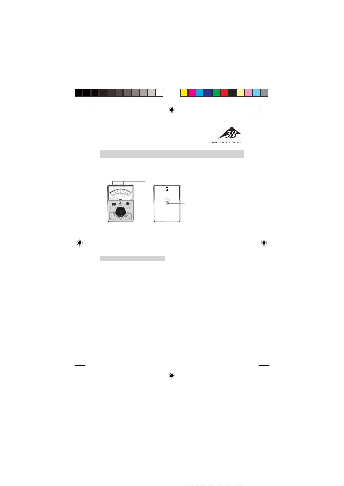
1 Rotary switch to select the
3
4
2
1
measurement range
2 Rotary knob to set the
6
electrical zero-point in the
center of the scale
3 Safety connection sockets
5
4 Slide switch to select the
operating mode
5 Adjustment screw to set the
zero-point mechanically
6 Nub to latch the housing
shut
Handheld meter for current and
voltage measurement.
1. Safety instructions
• Before using the analog multime-
ter, make sure you read the operating instructions carefully and
that you comply with them completely.
• The safety of the multimeter and
the person operating it can only
be guaranteed if it is used in accordance with the instructions. Do
not operate or handle this unit
incorrectly or inappropriately.
• The device may only be used by
persons, who are aware of the hazards of contact (for voltages over
30 V rms) and can undertake the
appropriate safety precautions.
This also includes the appearance
of unforeseen voltages e.g. in defective units or charged capacitors.
• In the case of voltage and current
measurements the nominal voltage between the phase and neutral conductor may not exceed 300
V according to CAT II (in circuits
that are directly connected to the
mains) and CAT III (in building wiring installations) 300 V.
• The analog multimeter may be
used for measurements in circuits
with corona discharge (high voltage).
• In measurements involving RF cir-
cuits special care must be taken
due to the existence of dangerous
hybrid voltages.
• The appropriate permissible mea-
surement range may not be exceeded. Always change from a
higher measurement range to a
6
Page 2
lower measurement range.
• Before using the device, check the
housing and the measurement
cables for any damage.
• Do not conduct measurements in
a damp environment. Workplace,
hands, shoes and floor must be
dry.
• Before opening the housing all
measurement leads are disconnected from the device.
2. Description, technical data
Active analog multimeter with a
slide switch for selection of the operating mode and a rotary switch to
select the measurement range as
well as a scale with the mirrored
background for parallax-free readings with a zero-point adjustable to
the center or the left of the scale.
By adjusting the electrical zero-point
to the center of the scale bipolar DC
voltage and current measurements
can be conducted without worrying
about polarity. The device is extremely robust in terms of load capacity and is equipped with excellent overload protection due to its
two anti-parallel diodes as well as
moving coil movement which is not
sensitive to external electromagnetic fields. The safety connection sockets offer protection against accidental touch contact. After approx. 45
mins the battery is automatically
switched off. The power can be reestablished by turning off and on
using the slide switch for the operating mode. The robust plastic housing and the spring-connected bearing jewels of the movement guarantee protection against damage
caused by mechanical stress.
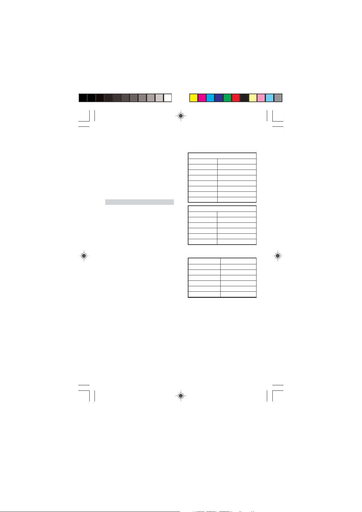
Measurement ranges:
Voltage measurement:
DC
Meas. range Internal resistance
100 mV 10 MΩ
300 mV 10 MΩ
1 V 10 MΩ
3 V 10 MΩ
10 V 10 MΩ
100 V 10 MΩ
300 V 10 MΩ
AC
Meas. range Internal resistance
3 V 1 MΩ
10 V 1 MΩ
30 V 1 MΩ
100 V 1 MΩ
300 V 1 MΩ
Current measurement AC/DC:
Meas. range Voltage drop
0.1 mA 55 mV
1 mA 55 mV
10 mA 55 mV
100 mA 55 mV
1 A 53 mV
3 A 51 mV
Accuracy: DC class 2; AC class 3
Effective variables and nominal operating ranges:
Temperature 0 – 40° C: ± 2% / K
Frequency for all measurement
ranges: ±2.5% at 30 Hz up to
1.5 kHz ± 5% at 1.5 kHz
up to 3 kHz
Reference conditions:
Ambient temperature: +23° C ± 2 K
Frequency: 50 to 60 Hz
Waveform: Sinusoidal
7
Page 3

Overload protection:
+
F3 fuse, 15 H/250 V in accordance
with DIN VDE 0820 Section 22/EN 60
127-2 as circuit protection in the
case of overload; movement protected by 2 antiparallel-connected diodes
Protection class:
IEC 1010-1/EN 61010-1/ VDE 0411-1
Overvoltage category: CAT III
Nominal voltage: 300 V
Degree of pollution: 2
Test voltage: 3.7 kV~
EMV: Electromagnetic compatibility
Jamming: EN 50081-1:1992
Interference
immunity: EN 50082-1:1992
Power supply: 1 x 9 V flat cell battery, IEC 6F22
Dimensions: 98 x 138 x 35 mm
Weight: approx. 0.3 kg
3. Operation
3.1 Readying for use
• Insert battery into the battery
compartment. To do this remove
the section of housing by pressing
in the nub (6), e.g. using a screwdriver. Then insert the battery and
connected it to the battery clip.
Replace the housing section and
snap it into place.
• Check the mechanical zero-point.
The measuring instrument may
not be connected at this time. Set
the sliding switch (4) to the “0”
position. The needle must be located in the “ OFF” position
when the multimeter is in a horizontal position. If necessary make
the corresponding adjustments
with the adjustment screw (5).
• Check the electrical zero-point. Set
the slide switch (4) into the “ ”
position. Select the measurement
range, the needle must be set to
zero-point in the center of the
scale, otherwise correct using the
rotary knob (2).
• Check the battery. To do this set
the slide switch (4) to “ ” , and
then adjust the rotary switch (1)
to“ ”. If the needle does not deflect into the battery test zone designated “ ” the battery must be
replaced.
3.2 General instructions
• When performing measurements
always set the rotary switch (1) to
the highest measurement range.
Then turn the switch to lower ranges until you obtain optimum needle deflection.
• When the power supply is inter-
rupted by the automatic battery
switch-off (after approx. 45 min.)
switch the slide switch (4) on and
off again.
• When the multimeter is not in use,
disconnect all measurement leads
from the meter, reset the rotary
switch (1) to the highest range, set
the slide switch (4) to the “0” setting and, if necessary, remove the
battery.
3.3 DC voltage measurement
_
8
Page 4

3.3.1 Operating mode: electrical
_
+
3.3.2 Operating mode: electrical
zero-point center
• Set the slide switch (4) to the “ ”
setting.
• Using the rotary switch (1) select
the corresponding measurement
range “V ...”.
• The needle should now be posi-
tioned in the center of the scale.
• Connect the multimeter and take
a reading from the lower scale.
3.4 Measuring alternating
voltage, directly up to 300 V
~
• Set the slide switch (4) to “ ”
setting.
• Using the rotary switch (1) select
the corresponding measurement
range “V~”.
• Connect the multimeter and take
a reading from the upper scale.
• To reduce the effects of the fre-
quency, connect the socket “
directly to ground or to the point
with the lowest potential with respect to ground.
3.5 Measuring AC voltage with
superimposed DC voltage
⊥⊥
⊥”
⊥⊥
~
• With the aid of a capacitor (recom-
mended: 4.7 µF/630 V) it is possi-
ble to isolate DC-voltage components in an amplifier output stage,
for example. The resultant measurement error is less than 0.2%
at a measurement frequency of
50 Hz.
• Proceed with the measurement as
stated in point 3.4.
• Measurement of the DC voltage
components is performed as described under 3.3.
• To avoid overloading, the set mea-
surement range must be greater
than the initially determined DC
voltage components.
• Caution: before switching to a low-
er measurement range both voltage components must be checked.
3.6 Current measurement
• When performing current mea-
surements the multimeter must
be connected in series with the
load in the circuit, which has the
lowest potential with respect to
ground.
3.6.1 DC measurement, directly
3.6.1.1 Operating mode: electrical
zero-point left
• Switch the slide switch (4) to the
“ ” setting.
• Using the rotary switch (1), select
the corresponding measurement
range “A ...”.
• Connect the multimeter take a
reading from the upper scale.
9
Page 5

3.6.1.2 Operating mode: electrical
_
+
~
zero-point center
• Adjust the slide switch (4) to the
“ ” setting.
• Using the rotary switch (1), select
the corresponding measurement
range “A ...”.
• The needle should be located in
the center of the scale.
• Connect the multimeter and take
a reading from the lower scale.
3.6.2 Measuring DC current using
shunts
3.6.2.1 Operating mode: Zero-point
left
• Set the slide switch (4) to the
“ ”.
• Set the rotary switch (1) to the “V ...
100 mV” setting.
• Connect the multimeter and the
take a reading from the upper
scale.
3.6.2.2 Operating mode: Zero-point
center
• Set the slide switch (4) to the “ ”
setting.
• Set the rotar y switch (1) to the “V ...
100 mV” position.
• The needle should now point to
the center of the scale.
• Connect the multimeter and take
a reading from the lower scale.
3.6.3 Measuring AC current
• Set the slide switch (4) to the “ ”
setting.
• Use the rotary switch (1) to select
the corresponding measurement
range “A~”.
• Connect the multimeter and take
a reading from the upper scale.
4 Maintenance
4.1 Cleaning
• Only use a paintbrush or soft tow-
el to clean the multimeter. If static electrical charge builds up on
the view window, this can be eliminated using a damp rag or an antistatic agent.
4.2 Replacing the battery
• If during the battery test the nee-
dle no longer deflects to the battery test zone depicted with “ ”,
the battery must be replaced (see
3.1).
4.3 Replacing the fuse
• The multimeter is equipped with
a safety fuse F3,15/250. The fuse
holder is located on the printed
circuit board. To replace the fuse
the device must be opened as described in section 3.1.
3B Scientific GmbH • Rudorffweg 8 • 21031 Hamburg • Ger many • www.3bscientific.com • Technical amendments are possible
10
 Loading...