

Page 1
PHYSICAL EXPERIMENTS
ON THE
AIR-CUSHION TABLE
U15420
Page 2

Physical Experiments on the Air-Cushion Table
Table of Contents
Introduction ........................................................................................................................ 5
1. Setup and Possible Uses of the Air-Cushion Table ........................................................... 6
1.1 Components of the experimenting apparatus ......................................................................... 6
1.2 Principle Uses of the Air-Cushion Table ............................................................................. 11
1.3 Setup of the Air-Cushion Table ............................................................................................ 11
1.4 Instructions for Usage .......................................................................................................... 12
1.5 Maintenance and Care .......................................................................................................... 13
2 Description of the Experiments ........................................................................................ 14
2.1 Structure and Properties of Gases ...................................................................................... 14
2.1.1 Motion of a Molecule in High Vacuum ............................................................................... 14
2.1.2 Motion of the Molecules in a Gas ........................................................................................ 14
2.1.3 Dependence of the Number of Impacts with the Vessel Wall on the
Velocity of the Molecules .................................................................................................... 15
2.1.4 Dependence of the Number of Impacts with the Vessel Wall on the Volume...................... 15
2.1.5 Mean Velocity of the Molecules – Temperature of a Gas .................................................... 16
2 1.6 Mean Velocity of the Molecules – Influence on Foreign Molecules ................................... 17
2.1.7 Velocity of Molecules in a Gas Compound ......................................................................... 17
2.1.8 Mixing Temperature of Gases .............................................................................................. 18
2.1.9 Increase of Temperature in Gases when Supplying Energy ................................................. 19
2.1.10 Form and Volume Properties of Gases ................................................................................. 20
2.1.11 Adiabatic Compression and Expansion of Gases ................................................................ 21
2.1.12 Dependence of the Pressure on the Temperature ................................................................. 22
2.1.13 Dependence of the Pressure on the Number of Molecules .................................................. 22
2.1.14 Diffusion of Gases................................................................................................................ 23
2.1.15 Diffusion of a Gas through a Porous Partition ..................................................................... 24
2.1.16 Brownian Motion in a Gas ................................................................................................... 25
2.1.17 Density Distribution in a Gas in the Gravitational Field ..................................................... 26
2.1.18 Local Distribution of the Molecules in a Gas ...................................................................... 27
2.2 Structure and Properties of the Liquids ............................................................................. 29
2.2.1 Configuration and Motion of Molecules in a Liquid ........................................................... 29
2.2.2 Increase of Temperature in Liquids when Supplying Energy .............................................. 29
2.2.3 Diffusion of Liquids ............................................................................................................. 30
2.2.4 Brownian Motion in a Liquid............................................................................................... 31
2.2.5 Evaporation of a Liquid ....................................................................................................... 31
2.2.6 Liquefaction of a Gas through Pressure ............................................................................... 32
2.2.7 Solidification of a Liquid ..................................................................................................... 32
3
Page 3

Physical Experiments on the Air-Cushion Table
2.3 Structure and Properties of Solids ...................................................................................... 34
2.3.1 Configuration and Motions of the Lattice Elements in a Solid ............................................. 34
2.3.2 Melting a Solid ....................................................................................................................... 34
2.3.3 Change of the Aggregation State of a Gas through Compression and Cooling ..................... 35
2.3.4 Heat Conduction in Solids ..................................................................................................... 36
2.4 Processes of Electric Conduction ....................................................................................... 37
2.4.1 Motion of an Electron in a Vacuum Under the Influence of an Electric Field
(Demonstrated By Means of Mechanical Forces)................................................................ 37
2.4.2 Deflection of an Electron Radiation in the Electric Field .................................................... 37
2.4.3 Motion of Electrons in a Vacuum Under the Influence of an Electric Field........................ 38
2.4.4 Principle of Electric Conduction .......................................................................................... 39
2.4.5 Influence of Lattice Elements on the Motions of Electrons in an Electric Field ................. 39
2.4.6 Motion of an Electron in a Metal Lattice Under the Influence of the Electric Field
– Ohmic Resistance (Demonstrated By Means of Mechanical Forces)............................... 40
2.4.7 Motion of the Free Electrons in a Metal .............................................................................. 41
2.4.8 Thermal Emission ................................................................................................................ 41
2.4.9 Bound Charge Carriers in an Insulator................................................................................. 42
2.4.10 Behavior of a Free Charge Carrier in an Insulator ............................................................... 43
2.4.11 Electric Conduction in a Semiconductor – Intrinsic Conduction
(Demonstrated By Means of Mechanical Forces)................................................................ 43
2.4.12 Electric Conduction in a Semiconductor – N-Type Conduction
(Demonstrated By Means of Mechanical Forces)................................................................ 44
2.4.13 Electric Conduction in a Semiconductor – P-Type Conduction
(Demonstrated By Means of Mechanical Forces)................................................................ 45
2.5 Nuclear Physics ................................................................................................................... 47
2.5.1 Scattering of Positively Charged Particles Near an Atomic Nucleus .................................... 47
2.5.2 Scattering of Alpha Particles When Passing Through a Metal Foil ...................................... 47
2.5.3 The Rutherford Atomic Model .............................................................................................. 48
2.6 Mechanical Motions............................................................................................................ 49
2.6.1 Vertical, Horizontal and Diagonal Projection ...................................................................... 49
2.6.2 Elastic Collision ................................................................................................................... 49
2.6.3 Change in the Direction of Motion of an Object with a Force ............................................ 50
4
Page 4

Introduction
Physical Experiments on the Air-Cushion Table
Air cushions are produced and sustained by
means of air continuously emitted from jets in
one of the objects as they move against one another. This prevents any contact between the two
objects. As a “lubricant”, there is a thin gas cushion between them, similar to the oil film frequently used. Due to the much lower viscosity of the
air, friction is reduced to negligible levels.
Using the air cushion makes it possible to conduct many experiments in a much better quality.
A large number of experiments, however, are only
possible by making use of the air cushion.
A disadvantage of the common two-dimensional
air-cushion arrangement is limited visibility. To
observe the motions in two dimensions, it is necessary to step up closely to the setup. Such systems are furthermore very difficult to handle because of complicated stabilization and adjustment
procedures. The use of projection offers new
opportunities. It allows both an expedient reduction in the size of all parts of the experiment setup and a considerable improvement in visibility.
Finally, mechanical collisions proved to be too
inefficient. Since in this case only part of the energy is transmitted, it would have been necessary to take additional measures to compensate
for the loss of kinetic energy. Making use of the
forces between ceramic magnets allows the production of virtually fully elastic collisions. The
fact that an immediate contact between the colliding partners does not occur is no disadvantage
in most cases. This method is highly suited for
model demonstrations, e.g. of the force relations
on a microphysical level.
The gas cushion principle, use of projection and
use of magnetic forces make the air-cushion table a high-quality teaching aid, characterized by
simple operation, high reliability, universal usage and excellent methodological qualities. Some
of the experiments basically cannot be carried out
better with other currently known methods.
The air-cushion table is used mainly in model
demonstrations of microphysical procedures. The
characteristic vividness of models and the excel-
lent visibility make this demonstration a kind of
“window into the microcosm”. However, it is necessary to mind the shortcomings and limits of
modeling. Not only are the procedures highly simplified and represented in a purely mechanical
way, also the motions of the real objects are in
many cases determined by other forces. Furthermore, all procedures occur on one level. Finally,
models contain additional misrepresentations,
which become visible e.g. in the shape and color
of the hover discs.
Due to the relatively high throughput of air and
the small size of the hover discs additional driving mechanisms occur. The effect of these is that
the motion of the small, hover discs will not stop
as long as the airflow continues. This has the great
didactic benefit that many processes can be observed for any required duration, without any
need of intervention.
On the other hand, the limited force effect between the hover discs and between them and the
magnetic barriers determines a specific maximum
speed, which, in the case of very quick hover
discs, has practically been reached already after
one collision.
With the help of these mechanisms, optimal, wellvisible motions usually begin by themselves. The
driving mechanism increases the velocity; the not
fully elastic collisions limit it.
However, both mechanisms can also have an adverse effect by misrepresenting the motions of
interest. Only the knowledge of these processes
and their well directed usage or inclusion by the
experimenter allow full utilization of the great
potential of this valuable teaching aid.
On the following pages you will find a description of the setup and possible uses of the air-cushion table. Then you will find instructions for conducting important experiments.
The illustrations are meant to assist you in your
work. They are taken from the perspective from
which the teacher views the experiment setup on
the air-cushion table.
5
Page 5
Physical Experiments on the Air-Cushion Table
1. Setup and Possible Uses of the Air-Cushion Table
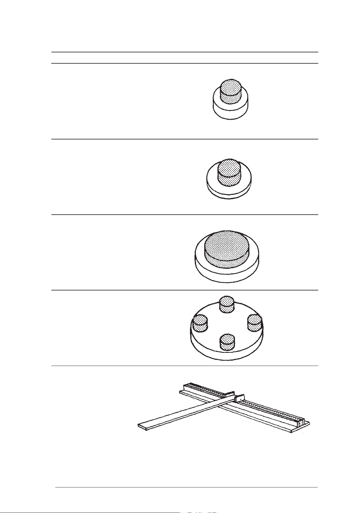
1.1 Components of the experimenting apparatus
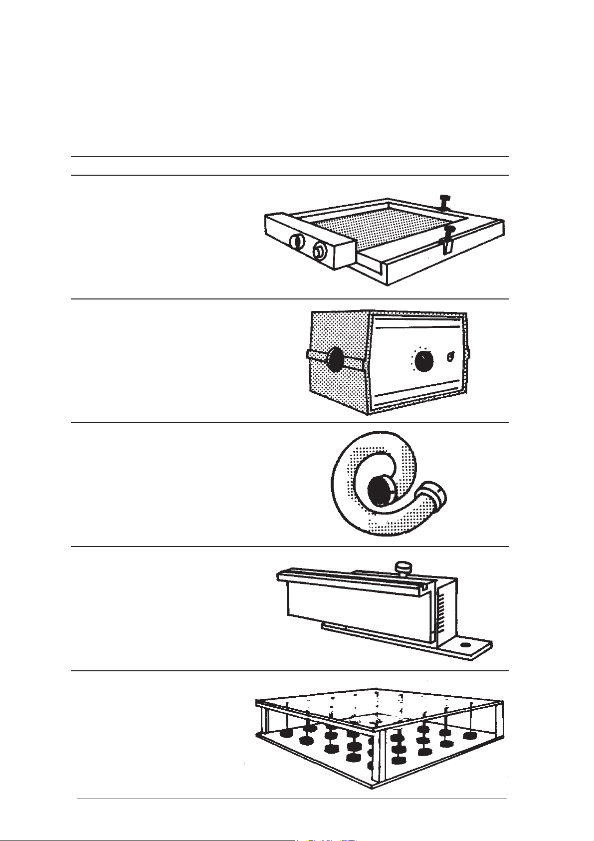
Item Quantity Drawing
Air-cushion table 1
Air source 1
Tube 1
Holding device 1
Lattice model 1
6
Page 6
Physical Experiments on the Air-Cushion Table
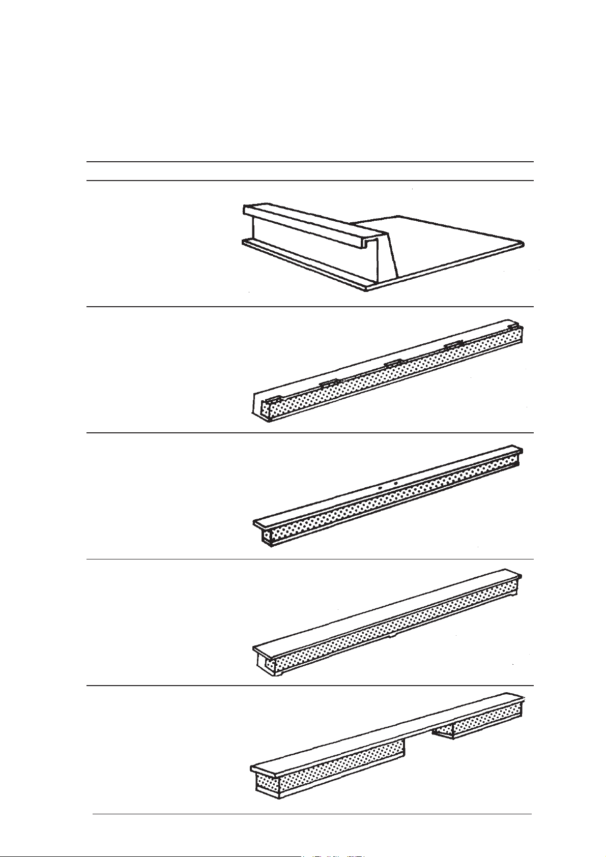
Item Quantity Drawing
Plexiglas plate 1
Magnetic barrier 2
253 mm (no. 3 and no. 4)
Magnetic barrier 1
233 mm (no. 2)
Magnetic barriere 1
233 mm with slit for airflow
from the side (no. 1)
Magnetic barrier 1
233 mm with opening
7
Page 7
Physical Experiments on the Air-Cushion Table
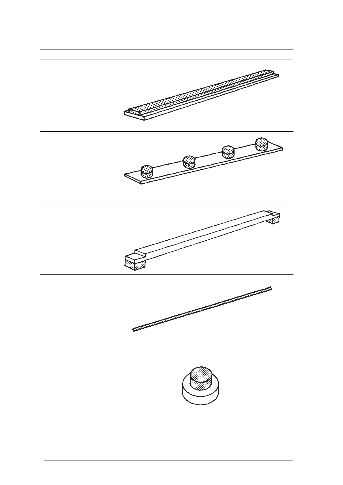
Item Quantity Drawing
Flat magnetic barrier 1
Magnetic barrier made 1
of 4 magnets
Electrodes 2
Manipulating rod 1
Magnetic hover disc 30
Ø 16 mm, red
8
Page 8
Physical Experiments on the Air-Cushion Table
Item Quantity Drawing
Magnetic hover disc 25
Ø 16 mm, green
Magnetic aluminum 5
hover disc, Ø 21 mm
Magnetic hover disc 25
Ø 28 mm, orange
Magnetic hover disc 2
Ø 48 mm, blue
Magnetic piston 1
9
Page 9

Physical Experiments on the Air-Cushion Table
Item Quantity Drawing
Guide piece for the 1
magnetic piston
Fastening screws for 2
the holding device
Plastic tweezers 1
Aufbewahrungskasten 1
10
Page 10

1.2. Principle Uses of the Air-Cushion Table
The system kit allows for
- nearly frictionless movement of the hover
discs
- through the air cushion
- modeling the interactions between the microobjects and the field
- through magnetic forces
- through electrical forces
- by tilting the experiment surface
- excellent visibility of all experiments
- due to projection with the overhead projector
- little preparation work
- due to clear and simple system setup
- since only few adjustments required
The experimenter can continually adjust the influence factors and directly intervene in the experimental procedure.
All of this ensures a large variety of uses, preferably to demonstrate the behavior of individual
microobjects or microobject systems. Therefore
it becomes possible to create moving, vivid and
highly simplified models of complicated physical objects and phenomena, which one cannot observe directly.
Some of the forces taking effect in model experiments vary considerably from those occurring
between the real objects. In many cases, however, the force-distance relations are very similar,
so that special attention only needs to be paid to
them in quantitative experiments.
Despite this limitation, the air-cushion table is a
versatile, effective and appealing teaching aid
when handled by a qualified and methodologically skilled experimenter. When teachers have
fully understood the operation of the system and
follow the operating instructions for the system
described below, they can demonstrate experiments with physically convincing and effective
results.
1.3. Setup of the Air-Cushion Table
air-cushion table is made up of a frame and
The
a pressure chamber. The cover plate of the pres-
sure chamber has 1089 holes (ø 0.8 mm). This is
the experiment surface. The side of the pressure
Physical Experiments on the Air-Cushion Table
chamber where the impulse valve is located is
connected to the fan using the tube. The experiment surface can be set to the horizontal or inclined position by means of two adjusting screws.
.
.
Five different types of
with the air-cushion table. They are made of colored, transparent plastic or aluminum discs, onto
which cylindrical, ceramic magnets are attached.
Carried by the air cushion, these hover discs simulate the moving objects.
The experiment surface is delimited by a flat plastic frame. It is also possible to attach magnetic
barriers allowing for almost fully elastic collisions of the hover discs. Therefore it becomes
possible to demonstrate interactions with the vessel walls.
To create an electric field, two rod-type electrodes
can be placed on the experiment surface. A model effect of an electric field can also be attained
by inclining the air-cushion table to the desired
degree.
The impulse valve can be used to create an airflow parallel to the experiment surface influencing the motion of the hover discs. This can be
used to increase the speed of the hover discs.
The fan ensures a sufficient air cushion over the
experiment surface. Its performance is continuously adjustable and can be adapted to the conditions of the experiment. The fan is equipped with
a delivery connection and a suction connection.
While experimenting with the air-cushion table,
the delivery connection is used, the suction connection can be used for other physical experiments (e.g. with the transparency panel apparatus).
The lattice model is made up of 25 ceramic magnets, which are suspended by thin steel wires. This
system oscillates with little absorption. It is used
to demonstrate e.g. the interaction of a metal lattice with the moving charge carriers as a model.
It is inserted into the holding device in the same
way as the Plexiglas plate. The height in which
these components are located above the experiment surface can be adjusted as individually suited for each experiment by means of the setscrew.
The settings can be easily reproduced using the
scale marks.
hover discs are supplied
11
Page 11
Physical Experiments on the Air-Cushion Table
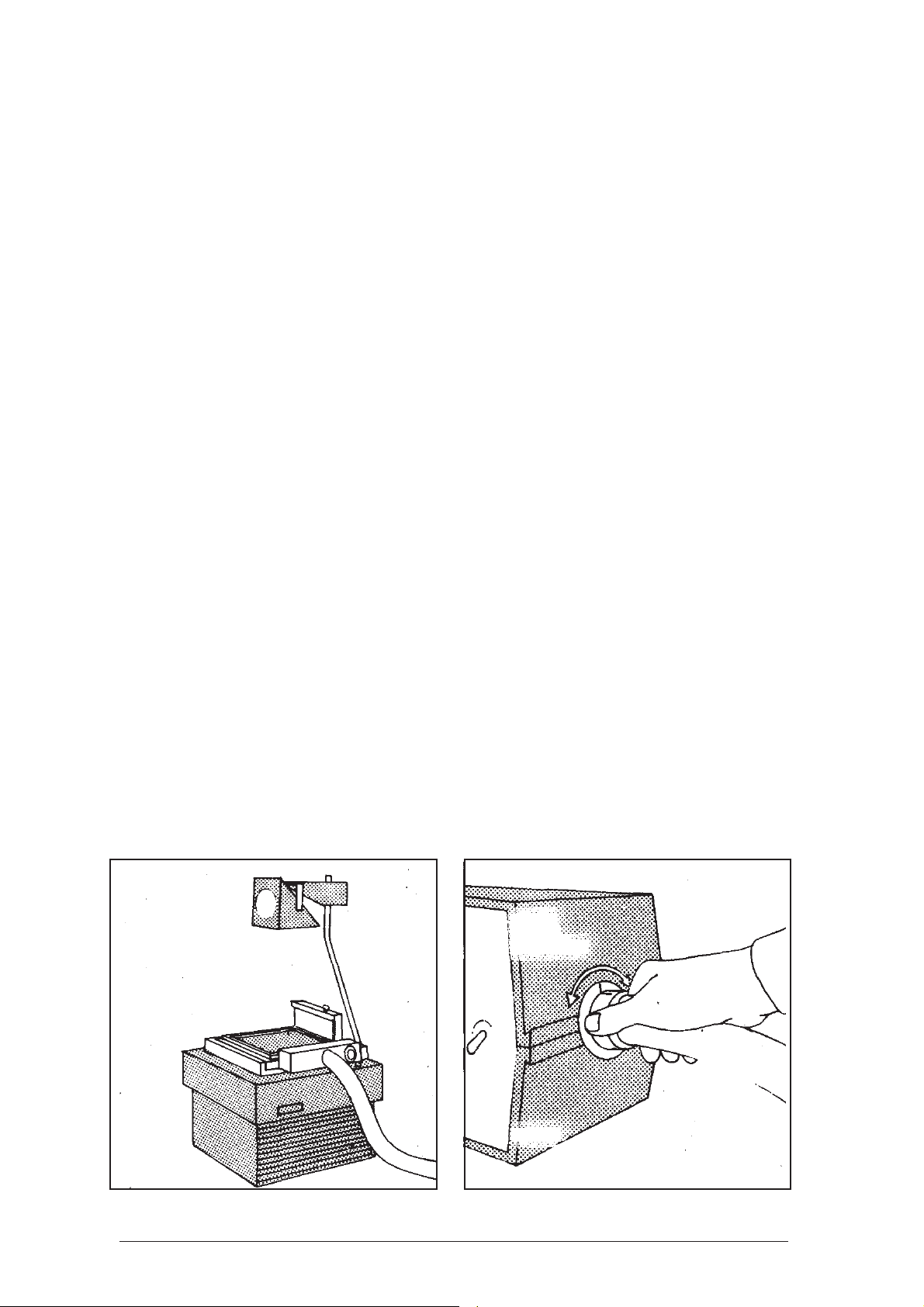
1.4. Instructions for Usage
The air-cushion table is placed onto the overhead
projector so that the arrow on the pressure chamber points to the projection screen. The magnetic
barriers (fig. 1) are placed onto the air-cushion
table so that their numbers (no. 1 to no. 4) match
the markings at the edges of the experiment surface. The magnetic barrier with the slit at the
bottom is arranged at the side of the table where
the tube of the fan connects. The air flows through
the slit and over the experiment surface when
activating the impulse valve.
The pressure chamber and the fan are connected
by the tube (fig. 2). The tube should run as straight
as possible. Only one position is possible when
connecting it to each of the devices. This is why
both ends of the tube and the connectors of the
devices are marked with a line. The tube is connected to the device so that both lines meet. Then
it is turned slightly to the right or to the left.
Next, the experiment surface is aligned horizontally by means of the adjusting screws at sides 2
and 4 by means of the spirit levels.
When needed, the impulse valve is pressed several times for approx. 1 second. The fan has to be
set to a sufficient performance level, since otherwise the pressure of the air cushion is too low
and the hover discs will sink onto the experiment
surface.
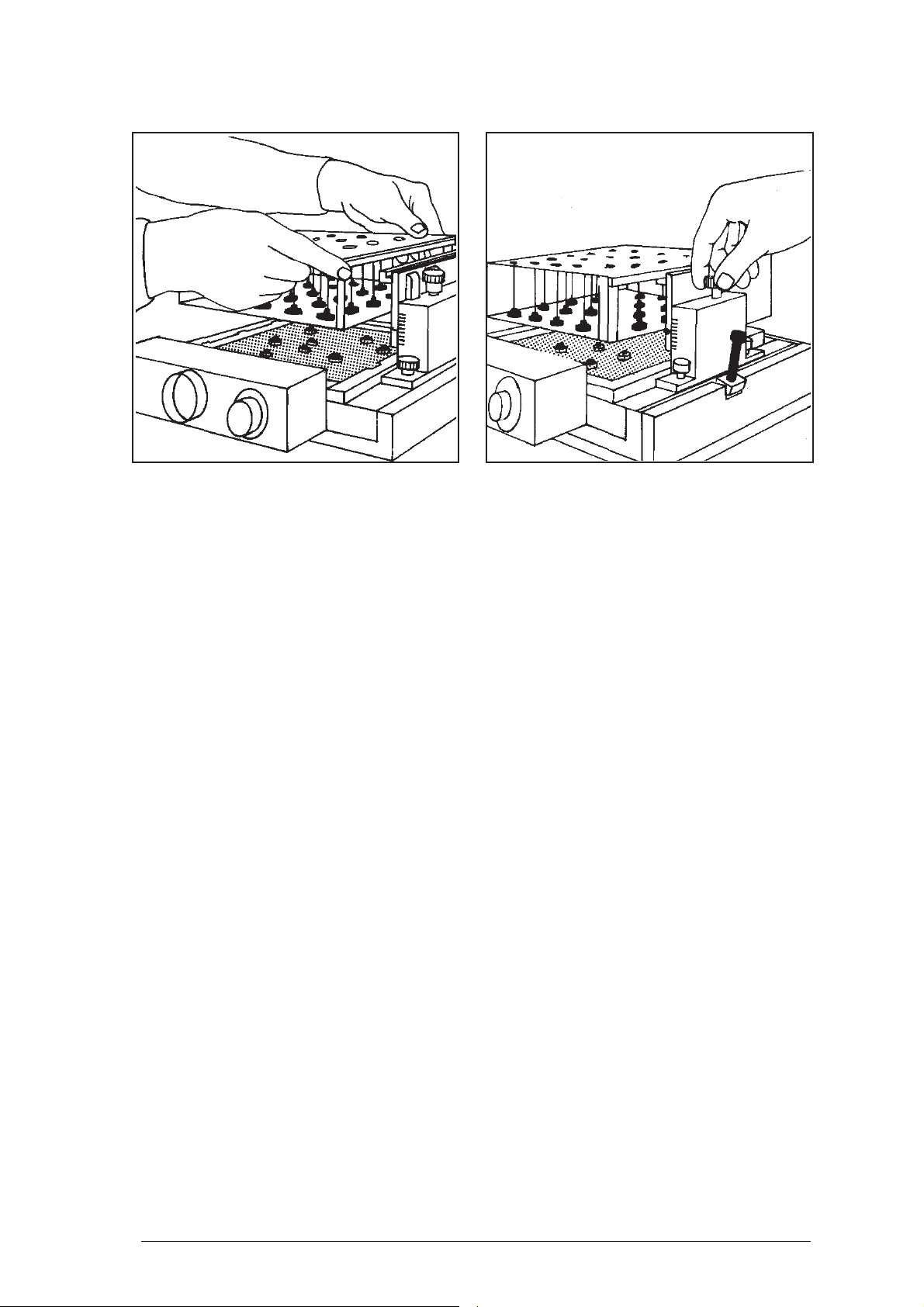
To install the lattice model, the holding device is
screwed onto the frame of the air-cushion table.
The lattice model is then inserted into the groove
of the holding device (fig. 3) The influence of
the lattice model on the motion of the hover discs
strongly depends on the height of the lattice over
the experiment surface. The holding device,
which is marked with a scale (fig. 4) can be infinitely adjusted to the appropriate height using a
setscrew.
This allows for demonstrations of the behavior
of conductors, semi-conductors and insulators.
The electrodes are used to create an electric field.
They can be applied in two positions. Placing
them onto their base will create a gap between
the experiment surface and the electrodes. This
gap is large enough for the aluminum hover discs
to fit through. These are then charged in accordance with the polarity of the respective electrode.
The electrodes can also be turned around so that
their bases point upwards. Then the aluminum
parts touch the experiment surface and the hover
discs contact the electrodes.
The voltage applied should be over 20 000 V.
When the voltage is lower, the electrodes have to
be arranged closer to each other.
An especially well-suited voltage source is the
electrostatic generator.
The influence of the electric field on the motion
of the hover discs can also be demonstrated by
slightly tilting the experiment surface. The degree of inclination then corresponds to the
strength of the electric field.
The strength of the fan is adjusted until the hover
discs just begin to move freely. This ensures a
relatively low level of noise. When the airflow is
stronger, disturbance caused by the noise of the
fan cannot be avoided. For this reason, it should
12
Page 12
Physical Experiments on the Air-Cushion Table
be positioned behind the experimenting table or
inside it. This will reduce the noise level reaching the classroom. Further
be reached by wrapping sponge rubber around
the fan or lining it with Piatherm or the like. Special care should be taken, though, to ensure that
the air can enter the suction nozzle unimpeded.
1.5. Maintenance and Care
The air-cushion table is a high-quality apparatus, which requires special care. Its stability has
certain limits because of the consistency of the
necessarily transparent material.
noise reduction can
- Avoid damage caused by dropping, hitting,
bumping, dragging or sliding.
- Keep all parts clean and free from dust.
- Remove dust with an anti-static cloth. Strong
rubbing of the table surface causes electrostatic charging which may considerably affect
the experiments.
- To keep the pressure chamber clean, do not
place the airflow generator near dust accumulations.
- Keep the bottom sides of the hover discs clean
at all times. They can be easily cleaned using
ethyl alcohol.
13
Page 13
Physical Experiments on the Air-Cushion Table
2 Description of the Experiments
2.1 Structure and Properties of Gases
2.1.1 Motion of a Molecule in High Vacuum
Components:
Air-cushion table with fan
Overhead projector
Magnetic barrier, long 2 Pieces
Magnetic barrier, short 2 Pieces
Hover discs l Piece
Model simulation
Real Object Model
Vessel containing Experiment surface of
the gas the air-cushion table
Walls of the vessel Magnetic barriers
Gas melecules Hover discs
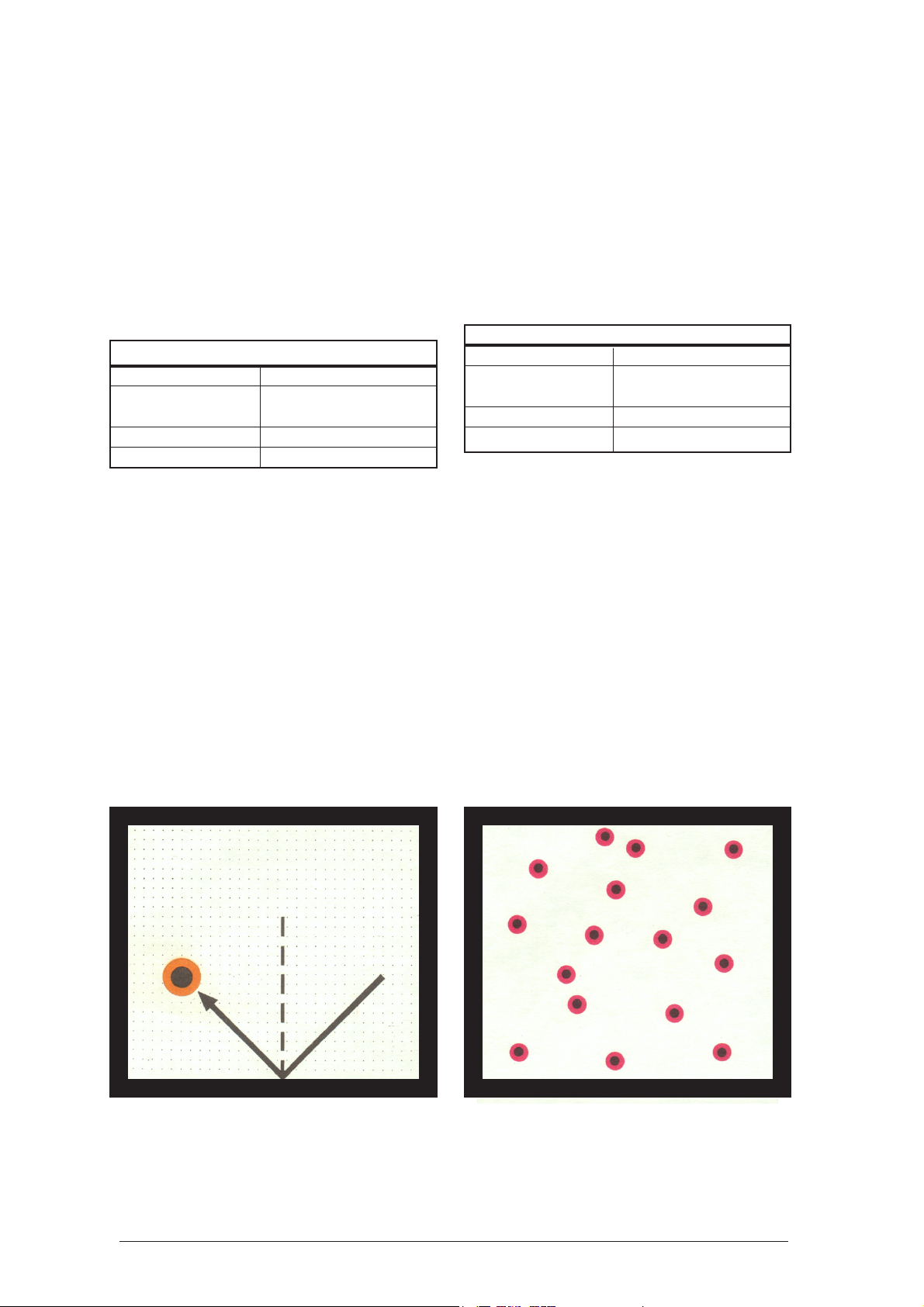
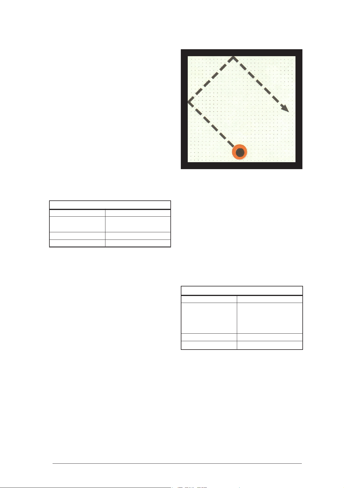
How to proceed:
Align the air-cushion table horizontally and attach
the magnetic barriers.
Turn the fan to a medium setting. Place the hover
disc onto the experiment surface and give it an
impact so that it hits a magnetic barrier in the
middle at an angle of 45°.
Result:
The motion of the hover disc is straight and uniform. When it hits a barrier, the direction of its
motion changes. The speed is unchanged. The
hover disc rebounds at the same angle at which it
hits the barrier. The law of reflection applies.
2.1.2 Motion of the Molecules in a Gas
Components:
Air-cushion table with fan
Overhead projector
Magnetic barrier, long 2 Pieces
Magnetic barrier, short 2 Pieces
Hover disc, red 16 Pieces
Model simulation
Real Object Model
Vessel containing Experiment surface of
the gas the air-cushion table
Walls of the vessel Magnetic barriers
Gas molecules Hover discs
How to proceed:
Align the air-cushion table horizontally and attach
the magnetic barriers.
Place the 16 red hover discs anywhere on the
experiment surface so that the spaces between them
are approximately 1 cm. Then turn the fan to a
setting in which all hover discs are sure to lift off.
Result:
Each hover disc moves in a straight and uniform
way as long as it does not hit any other hover disc
or a magnetic barrier. When two hover discs
collide, their speed and direction of velocity usually
changes. These collisions cause a transmission of
kinetic energy. When hitting the magnetic barrier,
only the direction of velocity changes.
Interpretation:
The gas molecule moves in accordance with the
laws of classical mechanics.
Interpretation:
Elastic collisions occur between the molecules
of a gas and when molecules hit the vessel wall.
Along the distance covered between two collisions, the “free length of path”, the motion of the
molecules is straight and uniform.
14
Page 14
Note:
This experiment can be developed from the one
described above in 2.1.1. by placing three additional
orange hover discs onto the experiment surface one
after the other while keeping the fan turned on. The
collisions between the discs and the transfer of
kinetic energy caused by them can be especially well
observed when using a low number of discs.
2.1.3 Dependence of the Number of Impacts
with the Vessel Wall on the Velocity of
the Molecules
Components:
Air-cushion table with fan
Overhead projector
Magnetic barrier, long 2 Pieces
Magnetic barrier, short 2 Pieces
Hover discs 2 Pieces
Stop watch or master clock l Piece
Physical Experiments on the Air-Cushion Table
Note:
The hover disc can also be set into motion so that
it hits the barriers at a perpendicular angle.
Model simulation
Real Object Model
Vessel containing Experiment surface of
the gas the air-cushion table
Walls of the vessel Magnetic barriers
Gas molecules Hover discs
How to proceed:
After aligning the air-cushion table horizontally,
attach the magnetic barriers.
Turn the fan to a setting in which two hover discs
placed above each other are sure to lift off. Give
this doubled hover disc an impact so that it hits
one of the barriers in the middle at an angle of
45°. Count the impacts with the wall occurring
within a given period of time (10 seconds).
Then repeat the experiment with only one of the
hover discs at a higher velocity.
Result:
The higher the velocity of the hover disc is, the
more often it will hit the magnetic barrier within
a specific period of time.
Interpretation:
The higher the velocity of the molecules is, the
more impacts of the gas molecules will occur with
the vessel wall. Since these impacts cause the
pressure, higher molecule velocities cause higher pressure.
2.1.4 Dependence of the Number of Impacts
with the Vessel Wall on the Volume
Components:
Air-cushion table with fan
Overhead projector
Magnetic barrier, long 2 Pieces
Magnetic barrier, short 2 Pieces
Hover disc, red l Piece
Hover disc, grün l Piece
Stop watch or master clock
Model simulation
Real Object Model
Vessel containing Experiment surface of
the gas the air-cushion table
surrounded by magnetic
barriers
Walls of the vessel Magnetic barriers
Gas molecules Hover discs
How to proceed:
Align the air-cushion table horizontally and attach
the magnetic barriers.
Turn the fan to a setting in which the hover discs
are sure to lift off. Then place both hover discs
into one corner of the experiment surface, first
holding them with two fingers and then quickly
releasing them. Count the number of impacts one
of the discs performs with the vessel walls within
a specific period of time (5 seconds).
15
Page 15
Physical Experiments on the Air-Cushion Table
Then reduce the area available for the hover discs
to half its size. To do this, lift up magnetic barrier
no. 2 and reattach it so that it separates the
experiment surface into two halves, with its ends
snapping into the recesses provided in barriers
no. 3 and no. 4. Now set both hover discs into
motion in the same way. Count the number of
impacts one of the hover discs performs with the
magnetic barriers within the same period of time
as in the previous experiment.
Result:
In the first experiment, the number of impacts with
the barriers is lower than in the second. By reducing
the area to half its size, the number of impacts
increases to approximately the double amount.
Interpretation:
Reducing the volume of a vessel containing a gas
causes an increase in the number of impacts of
the gas molecules with the vessel walls within a
specific period of time. Since the number of impacts occurring in a specific period of time with
a specific wall is an indicator of pressure, the
conclusion is that reducing the volume increases
the pressure.
Note:
Evaluation is easier when counting only the
impacts with magnetic barrier no. 2 in each of
the experiments. This, however, requires longer
times of measurement.
It is also possible to ascertain the total amount of
impacts of both discs. In this case it is recommended that one student counts the impacts of
the red disc while another student counts those
of the green. The results are then added up.
2.1.5 Mean Velocity of the Molecules
– Temperature of a Gas
Components:
Air-cushion table with fan
Overhead projector
Magnetic barrier, long 2 Pieces
Magnetic barrier, short 2 Pieces
Hover discs, red 16 Pieces
Model simulation
Real Object Model
Vessel containing Experiment surface of
the gas the air-cushion table
Walls of the vessel Magnetic barriers
Gas molecules Hover discs
How to proceed:
Align the air-cushion table horizontally and attach
the magnetic barriers.
Position all hover discs in one corner of the
experiment surface so that the spaces between
them are approximately 1 cm.
The fan is turned to a medium setting.
Sequentially observe the motions of each of the
hover discs. Draw attention to the velocity of each
disc in relation to the velocity of all other discs.
Gradually turn down the fan so that all hover discs
come to a stop and then turn it up again so that
they are sure to lift off. The same observations
are repeated at a lower velocity.
Result:
The velocity of each hover disc changes with each
impact. While an impact with the vessel wall
16
Page 16

Physical Experiments on the Air-Cushion Table
causes only a change in direction, a collision of
two hover discs usually causes a change in speed
as well.
At any given point in time, the majority of the hover
discs move at a mean velocity. Only few hover
discs have a high and few a very low velocity.
Interpretation:
The molecules in a gas have different velocities.
The velocity of each gas molecule changes with
each impact. Many molecules move at a velocity
that is close to the mean velocity. Only few molecules have a very low or high velocity. The distribution of velocity is constant over time in a large
number of molecules. The mean kinetic energy of
the molecules characterizes the temperature of the
gas. A low mean kinetic energy corresponds to a
low temperature, a large mean kinetic energy to a
high temperature. In each case there are molecules whose velocity is very low and others which
are especially fast.
Note:
To ensure better visibility of the motions of a
specific hover disc, use 15 red hover discs and 1
green one rather than 16 red ones.
Model simulation
Real Object Model
Vessel containing Experiment surface of
the gas the air-cushion table
Walls of the vessel Magnetic barriers
Gas molecules Green hover disc
Foreign gas Red hover disc
molecule
How to proceed:
Align the air-cushion table horizontally and attach
the magnetic barriers. Closely arrange the green
hover discs in one corner of the experiment
surface so that the spaces between them are
approximately 1 cm.
Turn up the fan so that all hover discs are sure to
lift off.
Place the red hover disc in the middle of the
experiment surface, holding it with the finger and
then releasing it so that it is not in motion at first.
Observe the motion it subsequently performs.
Then place the red hover disc directly into one
corner of the experiment surface, holding it with
the pointer and then quickly releasing it so that it
moves in the direction of the center at high
velocity.
Result:
In the first experiment, the red hover disc
repeatedly receives impacts from the green discs.
Its motion then no longer differs from that of the
others. In the second experiment, the velocity of
the red hover disc is reduced by collisions with
the green ones, so that its motion then also
corresponds to theirs.
Interpretation:
If a foreign gas molecule penetrates into a gas it
cannot continue in its state of motion. The interaction with the other gas molecules adapts its
motion to theirs after a short time.
2 1.6 Mean Velocity of the Molecules
– Influence on Foreign Molecules
Components:
Air-cushion table with fan
Overhead projector
Magnetic barrier, long 2 Pieces
Magnetic barrier, short 2 Pieces
Hover disc, green 12 Pieces
Hover disc, red l Piece
2.1.7 Velocity of Molecules in a Gas
Compound
Components:
Air-cushion table with fan
Overhead projector
Magnetic barrier, long 2 Pieces
Magnetic barrier, short 2 Pieces
Hover disc, red 12 Pieces
Hover disc, orange 2 Pieces
17
Page 17

Physical Experiments on the Air-Cushion Table
Model simulation
Real Object Model
Vessel containing Experiment surface of
the gas the air-cushion table
Walls of the vessel Magnetic barriers
Gas molecules Red hover disc
with small mass
Gas molecules Orange Hover discs
with large mass
How to proceed:
Align the air-cushion table horizontally and attach
the magnetic barriers. Place the hover discs anywhere
onto the experiment surface, so that the spaces
between them are not much more than 1 cm.
Turn the fan up to a setting at which all hover discs
are sure to lift off. Observe the motions of both
types of hover discs with regard to their velocity.
Result:
The mean velocity of the orange hover disc is
much lower than the mean velocity of the red
ones.
Interpretation:
In a compound of two gases whose molecules
have different masses, the molecules have different mean velocities. The molecules with the lesser mass move much faster than those with the
greater mass.
Since the temperature of the gas compound corresponds to the mean kinetic energy of
all mole-
cules, the mean kinetic energy of the molecules
−
2
1
Emv
with the lesser mass
=
has to be equal to
k
kk
2
the mean kinetic energy of the molecules with the
−
2
1
Emv
greater mass
=
This leads to the conclu-
g
gg
2
sion that in a gas compound of a given temperature the molecules of different masses have different mean velocities.
2.1.8 Mixing Temperature of Gases
Components:
Air-cushion table with fan
Overhead projector
Magnetic barrier, long 2 Pieces
Magnetic barrier, short 2 Pieces
Magnetic piston l Piece
Guide piece for the l Piece
magnetic piston
Hover disc, orange 4 Pieces
18
Page 18

Physical Experiments on the Air-Cushion Table
Model simulation
Real Object Model
Vessel containing Experiment surface
the gas of the air-cushion
Walls of the vessel Magnetic barriers
Partition Magnetic piston
Gas molecules Hover discs
How to proceed:
Align the air-cushion table horizontally and attach
the magnetic barriers. Divide the experiment
surface in half using the magnetic piston, parallel to the barriers nos. 1 and 2. For guidance of
the piston rod, place the guide piece for the
magnetic piston onto barrier no. 2.
Place two hover discs into each half.
Increase the fan setting so that both hover discs are
sure to float even when the impulse valve is opened.
Open the impulse valve repeatedly in order to set
the hover discs in the adjacent half of the experiment
surface into strong motion, while ensuring lesser
motion of the other two discs, if necessary by
slowing them down manually. Now quickly remove
the magnetic piston from the experiment surface
and observe the motion of all hover discs.
the resulting temperature is between the two initial temperatures. The reason for this is that the
molecules of the gas with the higher temperature
transfer part of their kinetic energy to the molecules of the gas with the lower temperature.
Note:
The experiment can also be carried out with 8
green and 8 red hover discs. This is a better demonstration of the conditions in a gas due to the
larger number of hover discs. However, it is more
difficult to maintain the difference in velocity.
For this reason, it is necessary to (manually)
accelerate the hover discs in one half and to slow
them down in the other.
2.1.9 Increase of Temperature in Gases when
Supplying Energy
Components:
Air-cushion table with fan
Overhead projector
Magnetic barrier, long 2 Pieces
Magnetic barrier, short 2 Pieces
Hover disc, red 12 Pieces
Hover disc, green 4 Pieces
Result:
The fast discs partially transfer their energy onto
the slow ones. The mean velocity of all four hover
discs is lower after the removal of the piston than
the velocity of the two fast discs in the one half
and higher than that of the two slow ones in the
other half.
Interpretation:
When mixing two gases of different temperatures,
Model simulation
Real Object Model
Vessel containing Experiment surface
the gas of the air-cushion
Walls of the vessel Magnetic barriers
Gas molecules Red hover disc
Molecules with Green hover disc
higher energy
How to proceed:
After aligning the air-cushion table horizontally,
19
Page 19

Physical Experiments on the Air-Cushion Table
attach the magnetic barriers and spread the red
hover discs evenly on the experiment surface.
Provide an airflow just ensuring that all hover
discs lift off. This keeps the mean velocity of the
red discs low. Shortly afterwards, make the 4
green hover discs shoot between the red ones at
the highest possible speed. This can be done in
quick succession from one corner, using the
pointer to hold each hover disc directly in the
corner and then quickly releasing it.
It is also possible to press all 4 hover discs against
a barrier at the same time, holding them with the
fingers and then releasing them so that they hit
the red hover discs at high speed.
Result:
The green hover discs shooting in at high speed
cause a noticeable increase of the mean velocity
of the red hover discs.
2.1.10 Form and Volume Properties of Gases
Components:
Air-cushion table with fan
Overhead projector
Magnetic barrier, long 2 Pieces
Magnetic barrier, short 2 Pieces
Magnetic piston l Piece
Hover disc, green 12 Pieces
Model simulation
Real Object Model
Vessel containing Experiment surface of
the gas the air-cushion table
surrounded by the
magnetic barriers and
the magnetic piston
Walls of the vessel Magnetic barriers
Piston to change the Magnetic piston
form and volume of
the area available
for the gas
Gas molecules Hover disc
Interpretation:
When supplying energy to a gas, its temperature
will rise. The energy supply can be interpreted as
shooting in of particles with high velocity, mixing
with a gas of higher temperature or heating.
Note:
Energy can also be supplied by repeatedly
opening the impulse valve for a short time. To
ensure that the hover discs will float safely even
when the valve is opened, a stronger airflow will
be necessary.
To repeat the experiment, slowly reduce the
airflow until the motions stop and then return to
the original setting.
How to proceed:
Align the air-cushion table horizontally and attach
the magnetic barriers. Attach the magnetic piston
to divide the experiment surface in two halves.
Closely arrange the hover discs in one half so
that the spaces between them are not much more
than 1 cm.
The fan is turned up to a setting in which all hover
discs are sure to lift off. The area available for
the hover discs is increased by quickly removing
the piston.
The piston is placed back onto the experiment
surface near a barrier and its rod is moved back
and forth to the right and left so that the shape of
the experiment surface available for the hover
discs changes.
Observe the reaction of the hover discs to the
change in area in both cases.
Result:
In both experiments, the hover discs completely
fill out the available area. They are quickly dispersed across the entire area.
Interpretation:
In beiden Experimenten füllen die Hover disc
die zur Verfügung stehende Fläche voll aus. Sie
verteilen sich dabei schnell auf die ganze
Fläche.
20
Page 20

Physical Experiments on the Air-Cushion Table
Note:
The experiments can be repeated using different
initial positions of the piston and different mean
velocities of the hover discs. The more closely
the discs are arranged at the beginning and the
higher their mean velocity is, the quicker they
will fill out the entire area.
2.1.11 Adiabatic Compression and Expansion
of Gases
Components:
Air-cushion table with fan
Overhead projector
Magnetic barrier, long 2 Pieces
Magnetic barrier, short 2 Pieces
Magnetic piston 1 Pieces
Guide piece for magnetic piston l Piece
Hover disc, red 10 Pieces
Model simulation
Real Object Model
Vessel containing Experiment surface of
the gas the air-cushion table
surrounded by the
magnetic barriers and
the magnetic piston
Walls of the vessel Magnetic barriers
Piston to change the Magnetic piston
volume of the gas
Gas molecules Hover disc
between them are approximately 2.5 cm. Then
increase the fan setting so that all hover discs are
floating properly.
Rapidly move the piston to the opposite side so
that the area available for the hover discs is
reduced to approximately one fifth. Observe the
motion of the hover discs with regard to velocity
and impacts.
Then increase the area in the same way by moving
the piston back. Observe the motion of the hover
discs again.
Result:
When reducing the size of the area both the mean
velocity of the hover discs and the number of
impacts among each other and with the barriers
increase. When increasing the area, their mean
velocity decreases and the number of impacts is
reduced.
How to proceed:
Align the air-cushion table horizontally and attach
the magnetic barriers. Place the piston at the edge
of the experiment surface. To guide the piston
rod, place the guide piece for the magnetic piston
onto barrier no. 2. Spread the 10 hover discs
across the experiment surface so that the spaces
Interpretation:
Quick compression of a gas increases the mean
21
Page 21

Physical Experiments on the Air-Cushion Table
velocity of the molecules and the number of impacts. The temperature and pressure of the gas
increase. When expanding a gas adiabatically,
the mean velocity of the molecules decreases and
there is a drop in pressure and temperature.
2.1.12 Dependence of the Pressure on the
Temperature
Components:
Air-cushion table with fan
Overhead projector
Magnetic barrier, long 2 Pieces
Magnetic barrier, short 2 Pieces
Magnetic piston l Piece
Guide piece for magnetic piston l Piece
Hover discs 8 Pieces
Model simulation
Real Object Model
Vessel containing Experiment surface of
the gas the air-cushion table
surrounded by the
magnetic barriers and
the magnetic piston
Walls of the vessel Magnetic barriers
Piston limiting the Magnetic piston
volume of the gas
Gas molecules Hover disc
How to proceed:
Align the air-cushion table horizontally and attach
the magnetic barriers. Place the piston on the
experiment surface parallel to magnetic barrier
no. 2. To provide a lateral boundary for the piston
rod and to ensure its successful guidance, place
the guide piece for the magnetic piston onto
barrier no. 2. Place the hover discs onto the
experiment surface near barrier no. 1 with the
slit for the airflow entering the experiment surface
from the side. Move the piston towards this
barrier as far as possible.
Turn the fan to a setting that provides a strong
airflow. Increase the mean velocity of the hover
discs by repeatedly opening the impulse valve
for a short period. Observe the motions of the
hover discs and the piston.
Result:
The piston shifts through the impacts of the hover
discs at the rate at which the mean velocity of the
hover discs rises. This causes an enlargement of
the area available to the hover discs.
Interpretation:
Increasing the temperature of a gas causes a rise
in pressure when the volume is constant. If the
vessel containing the gas is equipped with a moving piston, a rise in temperature will increase the
volume of the gas.
Note:
The force acting on the piston from the outside
due to air pressure can also be demonstrated in
this experiment by slightly tilting the experiment
surface so that the hover discs have to push the
piston up a slope.
2.1.13 Dependence of the Pressure on the
Number of Molecules
Components:
Air-cushion table with fan
Overhead projector
Magnetic barrier, long 2 Pieces
Magnetic barrier, short 2 Pieces
Magnetic piston l Piece
Guide piece for the magnetic piston l Piece
Hover discs 8 Pieces
Model simulation
Real Object Model
Vessel containing Experiment surface of
the gas the air-cushion table
surrounded by the
magnetic barriers and
the magnetic piston
Walls of the vessel Magnetic barriers
Piston limiting the Magnetic piston
volume of the gas
Gas molecules Hover disc
22
Page 22

Physical Experiments on the Air-Cushion Table
How to proceed:
Align the air-cushion table horizontally and attach
the magnetic barriers around the experiment
surface. Arrange the piston parallel to magnetic
barrier no. 2. The piston rod rests on the guide
piece for the magnetic piston, which has been
attached onto magnetic barrier no. 2 and ensures
its guidance. Arrange three of the hover discs near
barrier no. 1, the barrier with the slit for air entering from the impulse valve. Move the piston as
far as possible towards this barrier.
Turn the fan to a setting providing a strong airflow.
Now bring one of the remaining discs after the
other onto the experiment surface, making each
shoot in at the highest possible speed starting from
barrier no. 1. Observe the motions of the hover
discs and the piston.
Result:
The piston shifts through the impacts of the hover
discs at the rate at which the number of discs
increases. This causes an enlargement of the area
available to the hover discs.
Interpretation:
Increasing the number of molecules in a specific
gas volume causes a rise in pressure. If the vessel containing the gas is equipped with a moving
piston, the volume of the gas will increase when
the number of molecules rises.
Note:
It is also possible to demonstrate the force acting
on the piston from the outside due to air pressure.
This is done by slightly tilting the experiment
surface so that the hover discs have to push the
piston up a slope to increase the area in size.
2.1.14 Diffusion of Gases
Components:
Air-cushion table with fan
Overhead projector
Magnetic barrier, long 2 Pieces
Magnetic barrier, short 2 Pieces
Magnetic piston l Piece
Hover disc, red 6 Pieces
Hover disc, green 6 Pieces
Model simulation
Real Object Model
Vessel containing Experiment surface
the gas of the air-cushion table
Walls of the vessel Magnetic barriers
Partition Magnetic piston
Molecules of Green hover disc
one gas
Molecules of the Red hover disc
other gas
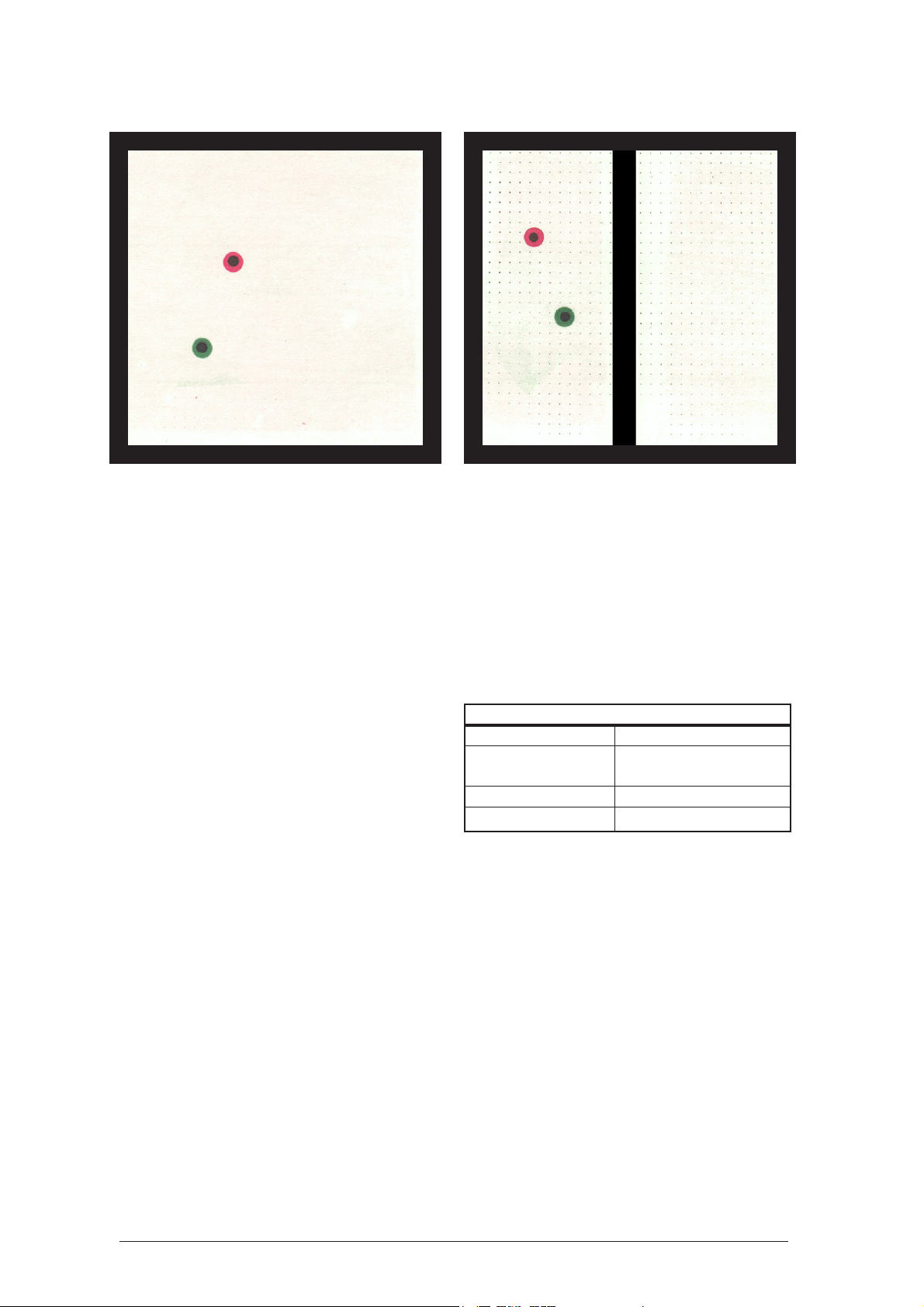
How to proceed:
Align the air-cushion table horizontally and insert
the magnetic barriers. Place the red discs in one
half of the experiment surface, near magnetic
barrier no. 1, and the green discs in the other half,
near barrier no. 2. Place the magnetic piston in
the center as a partition running parallel to barriers
no. 1 and 2.
Turn the fan to a low setting so that the hover discs
just lift off. Then quickly remove the piston and
observe the motions of the red and green discs.
Repeat the experiment using a stronger airflow
after placing the red discs close to barrier no. 1
and the green ones close to barrier no. 2.
23
Page 23

Physical Experiments on the Air-Cushion Table
Result:
After removing the partition, the hover discs mix
evenly as a result of their own motions. This will
occur more rapidly the higher the mean velocity
is.
Interpretation:
When removing the partition separating two gases contained in a vessel, these gases will mix by
themselves (diffusion). This process is caused by
the thermal motion of the molecules. The higher
the temperature, the higher the diffusion speed.
The reason for this is the higher velocity of the
molecules at higher temperatures.
As a result of diffusion, the system changes from
a state of a higher order to that of a lower order.
The entropy increases.
2.1.15 Diffusion of a Gas through a Porous
Partition
Components:
Air-cushion table with fan
Overhead projector
Magnetic barrier, long 2 Pieces
Magnetic barrier, short 2 Pieces
Magnetic barrier with opening l Piece
Hover disc, green 4 Pieces
Hover disc, red 6 Pieces
Model simulation
Real Object Model
Vessel containing Experiment surface
die Gase befinden of the air-cushion table
Walls of the vessel Magnetic barriers
Porous partition Magnetic barrier with
opening
Molecules of one gas Red hover disc
Molecules of the Green hover disc
other gas
How to proceed:
Align the air-cushion table horizontally and attach
the magnetic barriers. The magnetic barrier with
the opening divides the experiment surface in two
halves with its ends latching into the recesses provided in barriers nos. 3 and 4. The red discs are
placed in the half that is delimited by magnetic
barrier no. 1 with the slit for the airflow entering
from the side.
Select the lowest possible airflow at which the
discs are sure to float and observe their movement
through the opening of the middle barrier.
Repeat the experiment using a stronger airflow,
increasing the mean velocity of the hover discs
by repeatedly opening the impulse valve for a
short time, as opposed to the first experiment.
For the next experiment, place 4 green discs in
one half of the experiment surface and 4 red ones
24
Page 24

Physical Experiments on the Air-Cushion Table
in the other.
After turning the fan on, observe the movement
of the hover discs through the opening. Increase
the mean velocity of the hover discs by repeatedly
opening the impulse valve for a short time.
Result:
In all experiments hover discs move through the
opening at irregular intervals. As a result in the
first two experiments, each half contains
approximately the same amount of discs after
some time. In the last experiment the hover discs
penetrate the opening in both directions, so that
both types of discs mix. These procedures will
occur more rapidly the higher the mean velocity
of the hover discs is.
Interpretation:
The molecules of a gas can penetrate a porous
partition. If the gas is initially contained in one
chamber of a vessel with a porous partition, the
diffusion through the partition causes an equalization of pressure so that eventually both chambers contain the same amount of molecules. If the
two chambers of a vessel divided by a porous partition contain different gases, these gases will mix
through the partition. Diffusion will occur more
rapidly the higher the temperature of the gases is.
2.1.16 Brownian Motion in a Gas
Components:
Air-cushion table with fan
Overhead projector
Magnetic barrier, long 2 Pieces
Magnetic barrier, short 2 Pieces
Hover disc, red 16 Pieces
Hover disc, blue l Piece
Model simulation
Real Object Model
Vessel containing Experiment surface
the gas of the air-cushion
Walls of the vessel Magnetic barriers
Gas molecules Red hover discs
Particle showing the Blue hover disc
Brownian motion
How to proceed:
Align the air-cushion table horizontally and attach
the magnetic barriers around the experiment
surface.
Arrange the red discs near the magnetic barriers
of the air-cushion table. Place the blue disc at the
center of the experiment surface.
Set the fan to a medium setting. Observe the
motions of the blue disc.
25
Page 25

Physical Experiments on the Air-Cushion Table
Result:
The red discs hit the blue one at irregular
intervals, setting it into motion. Its speed and
direction of velocity change permanently,
resulting in a zigzag path.
Its average speed over time is much lower than
that of the red discs.
barriers.
Turn the fan to a medium setting. Use the
adjusting screw on barrier no. 4 to tilt the
experiment surface of the apparatus more and
more towards the projecting wall. Observe the
changing distribution of the hover discs on the
experiment surface.
Result:
At first, the hover discs are evenly distributed
across the entire experiment surface. As the inclination increases, the density of the hover discs
decreases from the bottom to the top.
Interpretation:
Small particles (dust, smoke particles, water
droplets), which are visible under the microscope,
perform a Brownian motion in gases. It is caused
by the disordered motion of the gas molecules.
2.1.17 Density Distribution in a Gas in the
Gravitational Field
Components:
Air-cushion table with fan
Overhead projector
Magnetic barrier, long 2 Pieces
Magnetic barrier, short 2 Pieces
Hover disc, red 20 Pieces
Model simulation
Real Object Model
Part of the earth’s Experiment surface
atmosphere of the air-cushion table
Gas molecules in the Hover discs
earth’s atmosphere
Gravitational field Inclination of the
experiment surface
How to proceed:
Align the air-cushion table horizontally and attach
the magnetic barriers on the experiment surface.
Arrange the hover discs near the magnetic
Interpretation:
Where gases are contained in the gravitational
field of the earth, the density of the gas decreases with increasing distance to the earth’s surface.
Note:
The experiment can also be evaluated
quantitatively. Divide the experiment surface e.g.
in 5 parallel horizontal strips of equal width. This
can be done by drawing lines on a transparency
inserted under the air-cushion table. Turn off the
fan and count the number of discs contained in
each strip. When the average numbers of discs
contained in each strip calculated in several
measurements are depicted graphically as a
function of height, the slope of the graph will be
nearly exponential.
The deviations occur because each hover disc
takes up a relatively large area and the repulsive
forces have a noticeable influence on the motion
even from a distance of several centimeters.
26
Page 26

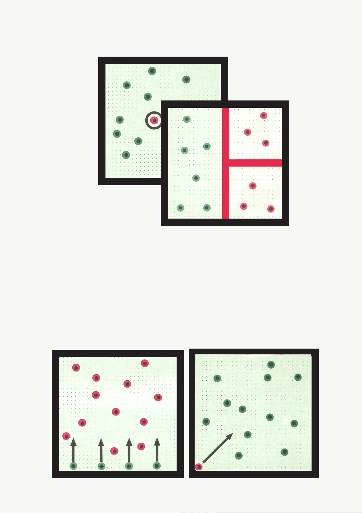
2.1.18 Local Distribution of the Molecules in
a Gas
Components:
Air-cushion table with fan
Overhead projector
Magnetic barrier, long 2 Pieces
Magnetic barrier, short 2 Pieces
Manipulating rod 1 Piece
Hover disc, red 4 Pieces
Stop watch or master clock
Model simulation
Real Object Model
Vessel containing Experiment surface
the gas of the air-cushion
Walls of the vessel Magnetic barriers
Halves of the vessel Halves of the
experiment surface
Gas molecules Hover discs
Physical Experiments on the Air-Cushion Table
and finally, considerably less often, the 4:0 and
0:4 distributions. The frequencies of the 3:1 and
1:3 distributions are approximately equal, as are
the 4:0 and 0:4 distributions.
How to proceed:
After aligning the air-cushion table horizontally,
attach the magnetic barriers at the edges of the
experiment surface. The experiment surface is
divided in half by placing the manipulating rod
onto the middle of barriers nos. 3 and 4. Spread
the discs anywhere across the experiment surface
and turn the fan to a medium setting.
Increase the motion of the hover discs to a high
mean velocity by repeatedly opening the impulse
valve for a short time. When a specified period
of time has elapsed, examine the distribution of
the 4 hover discs in both spaces. This is done by
covering the connector opening of the fan with
the hand. Record the calculated distribution in
table 1. Then release the opening again and open
the impulse valve several times. Cover the
opening again after the specified period of time,
record the distribution, etc.
Depict the relative frequency of each possible
distribution in a bar chart after 20 experiments,
40 experiments, etc. (Fig. 5)
Result:
Although the hover discs move in a completely
disorderly fashion, the result obtained from a
large number of experiments is that the
distribution across both halves is subject to certain
rules. The distribution occurring most frequently
is 2:2, followed by the 3:1 and 1:3 distributions
Interpretation:
The distribution of the molecules in a gas is governed by the laws of statistics. In the case of 4
molecules distributed onto 2 half spaces, the 0:4,
1:3, 2:2, 3:1 and 4:0 distributions occur at a ratio of 1 : 4 : 6 : 4 : 1. This corresponds to the
relative frequencies of 6.25 % : 25 % : 37.5 % :
25% : 6.25%.
Note:
An easier method to determine the individual
distributions is to calculate and record the
distribution after a specified period of time (e.g.
5 seconds). It is sufficient to observe only one
half of the experiment surface and to determine
how many hover discs it contains at the specified
points in time.
The number of hover discs contained in the other
half is obtained by deduction from 4.
The ratio of distributions given above is
applicable under the assumption that the
molecules have a very low volume and that the
repulsive forces are effective only in the immediate proximity of the molecules. These
conditions are not given in the case of the hover
discs used for demonstration. This is why the 2:2
distribution is overrepresented in the experiment,
while the other distributions occur less often than
expected.
27
Page 27

Physical Experiments on the Air-Cushion Table
Table 1
Distribution 0 : 4 1 : 3 2 : 2 3 : 1 4 : 0
Relative frequency in % 5 20 49 21 5
Relative frequency in %
40
20
0
:::::4132231400
Distribution
Fig. 5: Relative frequency of the distributions in 100 experiments
28
Page 28

Physical Experiments on the Air-Cushion Table
2.2 Structure and Properties of the Liquids
2.2.1 Configuration and Motion of Molecules
in a Liquid
Components:
Air-cushion table with fan
Overhead projector
Magnetic barrier, long 2 Pieces
Magnetic barrier, short 2 Pieces
Hover disc, orange 25 Pieces
Model simulation
Real Object Model
Vessel containing Experiment surface of
the liquid the air-cushion table
Walls of the vessel Magnetic barriers
Molecules of the Hover discsHover discs
liquid
How to proceed:
Align the air-cushion table horizontally. First
place the magnetic barriers on the experiment
surface and next the hover discs.
Turn the fan to a setting in which the hover discs
are sure to float even when the impulse valve is
opened. Briefly open the impulse valve several
times so that the mean velocity of the discs is as
high as possible.
Observe the arrangement and motion of the hover
discs.
Result:
The hover discs are irregularly arranged at short
distances. Each hover disc performs oscillating
and circular motions around its location.
However, it is not bound to any specific location,
rather changing it at irregular intervals or moving
on between the other discs.
The kinetic energy differs from disc to disc and
changes from time to time in each disc.
Interpretation:
The molecules of a liquid are in permanent, irregular motion, with prevailing oscillating and circular motions around the respective location. In
almost every molecule these motions are temporarily superimposed by irregular translational movements. The kinetic energy of the individual molecules varies and is constantly changing.
2.2.2 Increase of Temperature in Liquids
when Supplying Energy
Components:
Air-cushion table with fan
Overhead projector
Magnetic barrier, long 2 Pieces
Magnetic barrier, short 2 Pieces
Hover disc, orange 25 Pieces
Model simulation
Real Object Model
Vessel containing Experiment surface of
the liquid the air-cushion table
Walls of the vessel Magnetic barriers
Molecules of the Hover discs
liquid
How to proceed:
Align the air-cushion table horizontally and attach
the magnetic barriers. Place the hover discs on
the experiment surface.
Turn the fan to setting in which the hover discs
are sure to lift off. Initially, the velocity of the
hover discs has to be kept low by briefly opening
the impulse valve at rather long intervals.
Gradually increase the velocity by opening the
valve at shorter intervals. Observe the motion of
the hover discs.
29
Page 29

Physical Experiments on the Air-Cushion Table
Result:
As an increased amount of energy is supplied,
the motion of the hover discs becomes stronger.
They perform their oscillating motions at higher
amplitudes, exchange their locations more
frequently and move from one place to another
at higher speed.
Interpretation:
When supplying energy to a liquid, the mean kinetic energy of the molecules increases. The temperature rises.
2.2.3 Diffusion von Flüssigkeiten
Components:
Air-cushion table with fan
Overhead projector
Magnetic barrier, long 2 Pieces
Magnetic barrier, short 2 Pieces
Hover disc, red 20 Pieces
Hover disc, green 20 Pieces
Model simulation
Real Object Model
Vessel containing Experiment surface of
the liquid the air-cushion table
Walls of the vessel Magnetic barriers
Molecules of Red hover discs
one liquid
Molecules of the Green hover discs
other liquid
How to proceed:
Align the air-cushion table horizontally and place
the magnetic barriers on the experiment surface.
Spread the hover discs evenly across the entire
experiment surface so that all green discs are
arranged in one half and all red ones in the other
half and the line dividing them runs parallel to
barriers nos. 1 and 2.
Turn the fan to a setting in which the hover discs
are sure to float even when opening the impulse
valve. Observe the motions of the hover discs,
especially in the area around the borderline.
Result:
The hover discs gradually mix in the area of the
borderline as a result of the occasional
translational motions. With time, more and more
red discs move into the area of the green ones
and vice versa. After some time, the discs have
mixed completely.
Interpretation:
The disordered motions of the molecules causes
the liquids to mix by themselves. Due to the low
translation speed the diffusion in liquids occurs
much slower than in gases.
30
Page 30

Physical Experiments on the Air-Cushion Table
2.2.4 Brownian Motion in a Liquid
Components:
Air-cushion table with fan
Overhead projector
Magnetic barrier, long 2 Pieces
Magnetic barrier, short 2 Pieces
Hover disc, orange 25 Pieces
Hover disc, blue l Piece
Model simulation
Real Object Model
Vessel containing Experiment surface of
the liquid the air-cushion table
Walls of the vessel Magnetic barriers
Molecules of Orange hover discs
the liquid
Particle showing the Blue hover disc
Brownian motion
How to proceed:
Align the air-cushion table horizontally and attach
the magnetic barriers.
Arrange the orange discs near the magnetic
barriers of the air-cushion table. Place the blue
disc at the center of the experiment surface.
While the impulse valve is opened, turn up the
fan so that all hover discs lift off. Then briefly
open the impulse valve every now and then.
Observe the motion of the blue disc interacting
with the orange ones.
Result:
Repeated impacts of the orange discs cause a
disordered motion of the blue disc. Its mean velocity over time is much lower than the mean
velocity of the orange discs.
Interpretation:
If a liquid contains microscopically small particles the thermal motion of the invisible molecules sets them into an irregular motion which
can be observed under the microscope.
2.2.5 Evaporation of a Liquid
Components:
Air-cushion table with fan
Overhead projector
Magnetic barrier, long 2 Pieces
Magnetic barrier, short 2 Pieces
Holding device 1 Piece
Plexiglas plate 1 Piece
Flat magnetic barrier 1 Piece
Hover disc, green 10 Pieces
Model simulation
Real Object Model
Vessel containing Experiment surface of
the liquid the air-cushion table
Walls of the vessel Magnetic barriers
Surface of the liquid Flat magnetic barrier
Molecules of Hover discs
the liquid
How to proceed:
Align the air-cushion table horizontally and attach
the magnetic barriers. Then tilt the experiment
surface by screwing in the adjustment screw on
barrier no. 4. Arrange the hover discs on the half
of the experiment surface adjacent to barrier no.
3. Fasten the holding device to the air-cushion
table and insert the Plexiglas plate. Place the flat
magnetic barrier onto the Plexiglas plate so that
it runs parallel to the magnetic barriers nos. 3
and 4, below the center. The magnetic strip should
face down, with the arrow pointing to the
projecting wall. Then set the plate to the lowest
position.
Turn the fan to a medium setting. Observe the
behavior of the hover discs, especially those near
the flat magnetic barrier. Then gradually increase
the mean velocity of the hover discs by briefly
opening the impulse valve several times.
Result:
The slow hover discs cannot exit the lower part
of the experiment surface. The faster ones, however, cross this border and reach the upper section
of the experiment surface. Here they move in a
straight and uniform way until hitting other hover
discs or the magnetic barrier. Occasionally, discs
will also return to their original space.
31
Page 31

Physical Experiments on the Air-Cushion Table
The larger the mean velocity of the hover discs
is, the faster individual discs will leave the original section.
Interpretation:
A liquid contains molecules of different velocities at all times. The fastest among these molecules succeed in leaving the liquid. This process of
evaporation also occurs beneath the boiling temperature of the liquid. Since molecules from the
gas atmosphere also return into the liquid, a dynamic equilibrium state is soon reached.
The speed of evaporation increases as the temperature rises.
Note:
The inclination of the experiment surface simulates
the gravitational field. This makes more particles
return from the gas phase into the liquid phase.
2.2.6 Liquefaction of a Gas through Pressure
Components:
Air-cushion table with fan
Overhead projector
Magnetic barrier, long 2 Pieces
Magnetic barrier, short 2 Pieces
Magnetic piston 1 Piece
Guide piece for the
magnetic piston l Piece
Hover disc, red 20 Pieces
Model simulation
Real Object Model
Vessel containing Experiment surface of
the liquid the air-cushion table
Walls of the vessel Magnetic barriers
Piston for the com- Magnetic piston
pression of the gas
Gas molecules Hover discs
How to proceed:
Align the air-cushion table horizontally and attach
the magnetic barriers. Place the piston on the
experiment surface right next to barrier no. 2. The
guide piece for the magnetic piston placed onto
magnetic barrier no. 2 ensures excellent guidance
of the piston rod. Arrange the magnetic hover
discs near barrier no.1.
Turn the fan to a medium setting. Slowly move
the piston towards barrier no.1 until the available
area for the hover discs is less than half of the
experiment surface. Observe the configuration
and motions of the hover discs.
Result:
Reducing the area in size changes the behavior
of the hover discs. The number of impacts increases. The distances in which the hover discs
can move in a straight line become shorter and
shorter. Oscillating and circular motions prevail.
Permanent changes in location mostly occur as a
mutual exchange of positions.
Interpretation:
Under certain conditions, the compression of a
gas can result in liquefaction. The configuration
of the molecules and their type of motion change
in this process. While in the gaseous aggregation state only translational movements occur, the
motion prevailing in the liquid state is oscillation around the respective location.
2.2.7 Solidification of a Liquid
Components:
Air-cushion table with fan
Overhead projector
Magnetic barrier, long 2 Pieces
Magnetic barrier, short 2 Pieces
Air-cushion table with fan
Overhead projector
Magnetic barrier, long 2 Pieces
Magnetic barrier, short 2 Pieces
Hover disc, orange 25 Pieces
Model simulation
Real Object Model
Vessel containing Experiment surface of
the liquid the air-cushion table
Walls of the vessel Magnetic barriers
Molecules of the Hover discs
liquid
How to proceed:
Align the air-cushion table horizontally and attach
32
Page 32

Physical Experiments on the Air-Cushion Table
the magnetic barriers. Spread the hover discs
evenly across the experiment surface.
Adjust the airflow strong enough to ensure that
the hover discs lift off even when the impulse
valve is opened. Briefly open the impulse valve
several times so that the hover discs have a high
mean kinetic energy. Observe the motions of the
hover discs.
Result:
At first, the hover discs perform oscillating and
circular motions superimposed on their
translational movements. Their mean kinetic
energy gradually drops. The amplitudes of the
oscillations decrease, translational movements
occur less often. After a while there still are
occasional exchanges of position. Finally, each
hover disc only moves around its own equilibrium
position.
Interpretation:
Reducing the temperature of a liquid leads to its
solidification. The drop in temperature causes a
drop in the mean kinetic energy of the molecules
of the liquid. In the process of solidification, each
molecule occupies a specific location, around
which it performs irregular oscillating motions.
Note:
The mean velocity of the hover discs will drop
faster when the fan is turned to a lower setting.
33
Page 33

Physical Experiments on the Air-Cushion Table
2.3 Structure and Properties of Solids
2.3.1 Configuration and Motions of the
Lattice Elements in a Solid
Components:
Air-cushion table with fan
Overhead projector
Magnetic barrier, long 2 Pieces
Magnetic barrier, short 2 Pieces
Hover disc, orange 25 Pieces
Model simulation
Real object Model
Space in which the Experiment surface of
behavior of the solid the air-cushion table
is observed
Adjacent lattice Magnetic barriers
elements
Lattice elements Hover discs
of the solid
How to proceed:
Align the air-cushion table horizontally, attach
the magnetic barriers and spread the hover discs
evenly across the experiment surface. Adjust the
airflow strong enough so that the hover discs are
sure to float even when the impulse valve is
opened. Observe the motion of the hover discs
after opening the impulse valve once.
Result:
Each hover disc is bound to a specific location. It
performs oscillating and circular motions around
its equilibrium position. The amplitudes vary and
are constantly changing. The mean kinetic energy
of the hover discs gradually decreases.
Interpretation:
The lattice elements in a solid are arranged in a
regular configuration. They perform irregular
oscillations around their equilibrium position.
The amplitudes vary from location to location and
change with time. A drop in temperature makes
the mean kinetic energy of the oscillating lattice
elements decrease.
Note:
To provide a proper demonstration of the drop in
temperature it is recommended to turn the fan
down as far as possible during the experiment.
This experiment can also be demonstrated using
red or green discs. It will be necessary, however,
to reduce the effective experiment surface by
shifting barrier no. 2 to the middle of the aircushion table.
2.3.2 Melting a Solid
Components:
Air-cushion table with fan
Overhead projector
Magnetic barrier, long 2 Pieces
Magnetic barrier, short 2 Pieces
Hover disc, orange 25 Pieces
Real object Model
Space in which the Experiment surface of
behavior of the solid the air-cushion table
is observed
Adjacent lattice Magnetic barriers
elements
Lattice elements Hover discs
of the solid
Model simulation
How to proceed:
Align the air-cushion table horizontally and attach
the magnetic barriers. Spread the hover discs
evenly across the experiment surface.
Adjust the airflow strong enough so that all hover
discs are sure to float even when the impulse valve
is opened.
Open the impulse valve several times at an
interval of several seconds and observe the
motion of the hover discs.
34
Page 34

Physical Experiments on the Air-Cushion Table
Result:
Initially, the hover discs are arranged regularly
and perform oscillating and circular motions
around their respective location. Then the
amplitudes of their oscillations increase.
Individual discs change their position. In the end,
all discs temporarily perform translational
movements in addition to the oscillations.Result:
Initially, the hover discs are arranged regularly
and perform oscillating and circular motions
around their respective location. Then the
amplitudes of their oscillations increase.
Individual discs change their position. In the end,
all discs temporarily perform translational
movements in addition to the oscillations.
Interpretation:
A rise in temperature will make a solid body melt.
While initially all lattice elements are bound to a
fixed position around which they oscillate, there
will be a subsequent superimposition of the oscillations and translational movements.
Model simulation
Real object Model
Vessel containing Experiment surface of
the gas the air-cushion table
Walls of the vessel Magnetic barriers
Piston in the vessel Magnetic piston
Gas molecules Hover discs
How to proceed:
Align the air-cushion table horizontally and attach
the magnetic barriers. Place the piston close to
barrier no. 2. Attaching the guide piece for the
magnetic piston ensures excellent guidance of the
piston rod. Place the hover discs on the
experiment surface so that they are located near
barrier no. 1.
Turn up the fan so that all hover discs are sure to
lift off. Shift the piston very slowly from barrier
no. 2 towards barrier no. 1 until the piston has
crossed the center of the experiment surface.
Observe the motions of the hover discs.
2.3.3 Change of the Aggregation State of a
Gas through Compression and Cooling
Components:
Air-cushion table with fan
Overhead projector
Magnetic barrier, long 2 Pieces
Magnetic barrier, short 2 Pieces
Magnetic piston 1 Piece
Guide piece for the 1 Piece
magnetic piston
Hover disc, red 21 pieces
Result:
At first, the hover discs perform the same motions
as the molecules of a gas. The smaller the
available area becomes, the stronger the
impediment of the translational movements. In
addition, there are oscillations of the hover discs
around their respective location.
The hover discs change their equilibrium position
less often with time. Finally, each disc is located
in a fixed position around which it performs
oscillating and circular motions.
35
Page 35

Physical Experiments on the Air-Cushion Table
Interpretation:
An increase in pressure and a drop in temperature will transform a gas from the gaseous to the
liquid aggregation state. While the molecules
perform translational movements in the gaseous
state, the prevailing motions in the liquid state
are oscillations, superimposed by few translations. In the solid state, the lattice elements are
arranged in a regular configuration. They perform oscillations around their equilibrium position.
2.3.4 Heat Conduction in Solids
Components:
Air-cushion table with fan
Overhead projector
Magnetic barrier, long 2 Pieces
Magnetic barrier, short 2 Pieces
Hover disc, orange 25 Pieces
Model simulation
Real object Model
Space in which the Experiment surface of
behavior of the solid the air-cushion table
is observed
Adjacent lattice Magnetic barriers
elements
Lattice elements Hover discs
of the solid
How to proceed:
Align the air-cushion table horizontally and attach
the magnetic barriers. Spread the hover discs
evenly across the experiment surface.
Turn up the fan so that all hover discs are in
motion. Use one finger to set one of the hover
discs located in a corner of the experiment surface
into quick oscillating motions. (Take care to avoid
damage to the experiment surface caused by
friction.) Observe the motions of the hover discs.
Result:
The strong motion of the hover disc is gradually
transferred onto the other ones.The strong motion
of the hover disc is gradually transferred onto the
other ones.
Interpretation:
Energy is transferred by heat conduction in solids. A rise in temperature at one place of a solid
will increase the mean kinetic energy of the lattice elements at that place. Due to the forces between the lattice elements, the kinetic energy will
be transferred to the adjacent elements. This causes the temperature to rise also in other places of
the solid body.
36
Page 36

2.4. Processes of Electric Conduction
Physical Experiments on the Air-Cushion Table
2.4.1 Motion of an Electron in a Vacuum
Under the Influence of an Electric
Field (Demonstrated By Means of
Mechanical Forces)
Components:
Air-cushion table with fan
Overhead projector
Magnetic barrier, short 1 Piece
Hover disc, orange 1 Piece
Model simulation
Real Object Model
Space containing an Experiment surface of
electric field the air-cushion table
Strength of the Inclination of the
electric field experiment surface
Electron Hover disc
How to proceed:
Align the air-cushion table horizontally. Attach
magnetic barrier no. 2 in a reversed position with
the number facing downwards, in order to hold
the hover disc. Use the adjusting screw at barrier
no. 2 to lower the experiment surface on that side,
selecting a slight inclination.
Turn the fan to a medium setting. Place the hover
disc on the opposite side of the experiment surface,
holding it with the finger. Then release it and observe its motion. Repeat the experiment selecting a
stronger inclination of the experiment surface.
Result:
The motion of the hover disc accelerates. The acceleration increases with the degree of inclination.
Interpretation:
The motion of electrons in an electric field is accelerated, provided that no other forces act on
the electrons. The acceleration increases with the
intensity of the electric field.
2.4.2 Deflection of an Electron Radiation in
the Electric Field
Components:
Air-cushion table with fan
Overhead projector
Magnetic barrier, short 1 Piece
Electrode 2 Pieces
Manipulating rod 1 Piece
Hover disc, green 2 Pieces
Aluminum hover disc 5 Pieces
High-voltage source
Model simulation
Real Object Model
Vacuum containing Experiment surface of
an electric field the air-cushion table
Electrodes Electrodes
Electrons Aluminum hover discs
How to proceed:
Carefully align the air-cushion table in a horizontal position using the spirit levels. Place the
electrodes onto the experiment surface parallel
to sides nos. 1 and 2, so that the electrode on side
no. 2 rests on its bases, while the bases of the
other electrode point upwards. Position barrier
no. 2 outside of the experiment surface on side
no. 2, running parallel to the electrode on side
no. 2. It is turned by 180° so that the hover discs
cling to it because of the magnetic attraction.
Arrange 2 green hover discs closely to each other
on side no. 3. They are meant to give the aluminum disc a certain initial velocity. Feed the direct current of the high-voltage source to the electrodes. Use the manipulating rod to move an aluminum disc towards the electrode on side no. 1,
so that is charged. Then move it to the edge of
the experiment surface on side no. 3, between
the two green discs. Turn the fan to a medium
setting and observe the motion of the hover disc.
Repeat the experiment with the other aluminum
discs, varying the distance of the green discs from
the experiment surface.
37
Page 37

Physical Experiments on the Air-Cushion Table
Result:
The hover discs move towards the opposite electrode on a parabolic path.
Interpretation:
Electrons are subject to a force in the electric
field. When the electrons in a vacuum enter an
electric field at a perpendicular angle to the field
lines, they are forced onto parabolic paths. Their
velocity increases in this process.
zontal position using the spirit levels. Arrange
the electrodes at the edges of the experiment surface parallel to each other. The electrode on side
no. 2 is set on its bases, whereas the bases of the
other electrode point upwards. Place the magnetic
barrier, turned by 180°, closely to the experiment
surface parallel to the electrode on side no. 2, so
that the hover discs cling to it due to the magnetic attraction. Connect the electrodes to the
high-voltage source in such way that the anode
is located next to the magnetic barrier. Then place
the hover discs onto the cathode.
Feed d.c. voltage to the electrodes and turn the
fan to a medium setting. Then lift the hover discs
off the cathode using the tweezers and place them
onto the experiment surface one by one, positioning them directly in front of the cathode. Observe
their motions between the electrodes.
Result:
The hover discs move from one electrode to the
other in an accelerated way.
Note:
It is recommended to conduct this experiment without an electric field at first, in order to demonstrate
the straight, uniform movement of the electrons.
2.4.3 Motion of Electrons in a Vacuum Under
the Influence of an Electric Field
Components:
Air-cushion table with fan
Overhead projector
Electrode 2 Pieces
Magnetic barrier, short 1 Piece
Aluminum hover disc 5 Pieces
Plastic tweezers 1 Piece
High-voltage source
Model simulation
Real Object Model
Vacuum containing Experiment surface of
an electric field the air-cushion table
Electrodes Electrodes
Electrons Hover discs made of
aluminum
How to proceed:
Carefully align the air-cushion table in a hori-
Interpretation:
The electrons in a vacuum will move in an accelerated way from the cathode to the anode under
the influence of an electric field.
2.4.4 Principle of Electric Conduction
Components:
Air-cushion table with fan
Overhead projector
Electrode 2 Pieces
Hover disc made of aluminum 5 Pieces
Plastic tweezers 1 Piece
High-voltage source
38
Page 38

Physical Experiments on the Air-Cushion Table
Model simulation
Real Object Model
Space containing an Experiment surface of
electric field the air-cushion table
Electrodes Electrodes
Charge carriers Aluminum hover discs
How to proceed:
Align the air-cushion table horizontally. Arrange
the two electrodes on two sides opposite each
other, so that they rest directly on the experiment
surface with their bases pointing upwards. Connect them to the high-voltage source. Place a
hover disc directly next to an electrode.
Feed d.c. voltage to the electrodes. Turn the fan
to a setting in which the hover disc is sure to lift
off. Then place the remaining discs onto the experiment surface one after the other, using the
tweezers and placing them directly next to an electrode. Observe the motions of the hover discs.
Result:
The hover discs move back and forth between
the electrodes under the influence of the electric
field.
Notes:
This experiment offers a clear demonstration of
the conditions existing for example when grains
or aluminum flakes move back and forth between
the plates of a plate capacitor through the influence of the electric field.
This setup is also suited to simulate the process
of conduction with bipolar charge carriers. To do
this, place an approx. 8-cm wide cardboard strip
on each electrode. It should protrude from the
electrodes approx. 3 cm into the space between
the electrodes. When repeating the experiment
under these conditions, the charge carrier seems
to disappear in the respective electrode. Later it
will leave the electrode as a “different” charge
carrier (of the opposite polarity).
2.4.5 Influence of Lattice Elements on the
Motions of Electrons in an Electric Field
Components:
Air-cushion table with fan
Overhead projector
Holding device
Plexiglas plate
Electrode 2 Pieces
Manipulating rod 1 Piece
Hover disc, orange 1 Piece
Hover disc made of aluminum 4 Pieces
High-voltage source
Interpretation:
When slightly moving particles (charge carriers)
are located in an electric field, they will pick up
charges at one electrode and transport them to
the opposing one. There they will discharge these
and pick up charges of the opposite polarity. Then
they will return to the first electrode, etc. This
directed movement of the charge carriers represents a current.
Model simulation
Real Object Model
Part of a metallic Experiment surface of
conductor the air-cushion table
Lattice element Orange disc
of the metal
Electrodes Electrodes
Conduction electrons Aluminum hover discs
How to proceed:
Align the air-cushion table horizontally. Arrange
the two electrodes on two opposing sides of the
experiment surface, so that they rest directly on
its surface with their bases pointing upwards.
Attach the holding device to the air-cushion table
and insert the Plexiglas plate. Place the four aluminum discs on the experiment surface and shift
them towards one of the electrodes. Connect the
electrodes to the high-voltage source.
Feed d.c. voltage to the electrodes. Turn up the
fan so that all hover discs lift off. Observe their
39
Page 39

Physical Experiments on the Air-Cushion Table
motions. Then place the orange disc onto the
Plexiglas plate above the center of the experiment surface. Its magnet should face downwards
so that the aluminum discs are repelled. Set the
Plexiglas plate to different heights to vary the
influence of the orange disc on the aluminum
ones. Observe their motions.
Result:
At first, the hover discs move from one electrode
to the other and back. With the exception of few
mutual interferences, these motions are mostly
straight.
The influence of the orange disc is a major impediment to these motions. The aluminum discs
can often only succeed in reaching the opposite
side after taking major detours. The lower the
Plexiglas plate is set, the stronger the interference by the orange disc will be.
2.4.6 Motion of an Electron in a Metal
Lattice Under the Influence of the
Electric Field – Ohmic Resistance
(Demonstrated By Means of
Mechanical Forces)
Components:
Air-cushion table with fan
Overhead projector
Magnetic barrier, short 1 Piece
Holding device 1 Piece
Lattice model 1 Piece
Manipulating rod 1 Piece
Hover disc, orange 1 Piece
Model simulation
Real Object Model
Part of a metallic Experiment surface of
conductor the air-cushion table
Metal lattice Lattice model
Strength of the Inclination of the
electric field experiment surface
Electron Hover disc
Interpretation:
Conduction electrons move practically unimpeded between the lattice elements of a metal. However, near the lattice element there is strong interference.
Notes:
The fact that the directed movement of the electrons only occurs from the cathode to the anode
is neglected intentionally.
How to proceed:
Align the air-cushion table horizontally. Turn
magnetic barrier no. 2 by 180° and place it onto
its position on the experiment surface. Attach the
holding device to the air-cushion table and insert
the lattice model. Slide it along the groove of the
holding device until its edge at barrier no. 2 is
positioned above the last row of holes in the air
jet plate. This is to produce an approx. 3-cm wide
strip between the lattice model and the pressure
chamber through which the hover discs can be
placed onto the experiment surface. Set the lattice model to the lowest position. Use the adjusting screw at barrier no. 2 to select a slight inclination of the table by lowering the table part at
this side. Place the hover disc onto the experiment surface next to the pressure chamber.
Turn up the fan to make the hover disc float. Observe its motions and those of the hanging magnets. Repeat the experiment selecting different
degrees of inclination for the experiment surface.
Result:
The lattice model influences the motions of the
40
Page 40

Physical Experiments on the Air-Cushion Table
hover disc in such way that the mean drift velocity is constant. The hover disc is slowed down by
the interactions with the oscillating magnets. It
transfers part of its energy to the magnets so that
the amplitude of their oscillations increases. Both
the velocity of the hover disc and the amplitude
of the lattice oscillations increase as the degree
of inclination of the air-cushion table is increased
range the magnetic barriers around the experiment surface. Attach the holding device to the
air-cushion table and insert the lattice model. Set
it to its highest position. Place the hover discs
onto the experiment surface.
Turn up the fan so that all hover discs move freely
on the air-cushion table. Observe their motions and
interactions with the magnets of the lattice model.
Result:
The motions of the hover discs are similar to those
of the molecules of a gas. Interactions occur when
they approach a magnet of the lattice model. A
hover disc with a high velocity can make a hanging magnet oscillate at a higher amplitude. A
hanging magnet with higher oscillations can cause
the velocity of a hover disc to rise.
Interpretation:
The electrons in a metallic conductor move at a
constant mean velocity under the influence of an
electric field. In the course of interacting with
the lattice elements they transfer part of their
energy onto these, causing an increase in the lattice oscillations and therefore also a rise in the
temperature of the conductor.
2.4.7 Motion of the Free Electrons in a Metal
Components:
Air-cushion table with fan
Overhead projector
Magnetic barrier, long 2 Pieces
Magnetic barrier, short 2 Pieces
Holding device 1 Piece
Lattice model 1 Piece
Hover disc, red 25 Pieces
Model simulation
Real Object Model
Part of a metallic Experiment surface of
conductor the air-cushion table
Metal lattice Lattice model
Electrons Hover discs
How to proceed:
Align the air-cushion table horizontally and ar-
Interpretation:
The motions of conduction electrons in a metal
are similar to the motions of the molecules in a
gas. They interact with the lattice elements. A rise
in the temperature of the metal causes an increase
in the mean velocity of the electrons. An increased
velocity of the electrons causes a rise in the temperature of the metal.
2.4.8 Thermal Emission
Components:
Air-cushion table with fan
Overhead projector
Magnetic barrier, long 2 Pieces
Magnetic barrier, short 2 Pieces
Holding device 1 Piece
Lattice model 1 Piece
Hover disc, red 15 Pieces
Hover disc, green 11 Pieces
41
Page 41

Physical Experiments on the Air-Cushion Table
Model simulation
Real Object Model
Part of a metal Part of the experiment
surface under the
dynamic lattice
Vacuum Part of the experiment
surface not situated
under the dynamic
lattice
Metal lattice Lattice model
Electrons Hover discs
How to proceed:
Align the air-cushion table horizontally and arrange the magnetic barriers. Attach the holding
device and insert the lattice model. Set it to a
medium height. Slide it outwards in the groove
until 2 rows of the hanging magnets are located
above the impulse valve. Attach one red disc to
each hanging magnet of the remaining 3 rows.
These cling to the magnets due to the magnetic
attraction. Place the green discs on the experiment
surface and slide them under the lattice model.
Turn up the fan to a setting in which all discs are
sure to lift off. Briefly open the impulse valve
several times to increase the mean velocity of the
hover discs and the amplitude of the hanging
magnets. Observe the behavior of the hover discs.
Result:
Some of the hover discs overcome the forces of
the lattice magnets and return to the vacant area
of the air-cushion table. Some discs return to the
space underneath the lattice model. The stronger
the motions of the hover discs or lattice magnets,
the more hover discs escape the space under the
lattice model.
Interpretation:
To enable the electrons to escape the surface, they
have to possess a specific minimum energy. This
corresponds to the work of escape. Some of the
electrons possess this kinetic energy at high temperatures of the metal. The higher this temperature is, the more electrons can escape it in a specific period of time.
2.4.9 Bound Charge Carriers in an
Insulator
Components:
Air-cushion table with fan
Overhead projector
Magnetic barrier, long 2 Pieces
Magnetic barrier, short 2 Pieces
Holding device 1 Piece
Lattice model 1 Piece
Manipulating rod 1 Piece
Hover disc, red 25 Pieces
Model simulation
Real Object Model
Part of an insulator Experiment surface of
the air-cushion table
Crystal lattice of Lattice model
the insulator
Strength of the Inclination of the
electric field experiment surface
Electrons Hover discs
How to proceed:
Align the air-cushion table horizontally and attach the magnetic barriers. Spread the 25 hover
discs evenly across the experiment surface. Then
attach the holding device and insert the lattice
model. Set it to the lowest possible height, taking care, however, that the hover discs are not
attracted by the hanging magnets.
Turn the fan to a setting in which all hover discs
lift off. Observe their motions and interactions
with the lattice model. Then gradually increase
the degree of inclination of the experiment surface and observe the behavior of the hover discs.
Result:
All hover discs are tightly bound to their location and oscillate around their equilibrium position at low amplitudes. Even when the experiment surface is inclined to a higher degree, they
will not escape their positions.
42
Page 42

Interpretation:
In an insulator, the electrons are bound tightly to
the atomic nuclei. They cannot escape their positions even under the influence of an electric field.
Physical Experiments on the Air-Cushion Table
Position the orange disc in a corner of the experiment surface and hold it with the finger at
first. Then release it and observe the changes
caused by this hover disc.
Result:
The orange disc moves across the experiment
surface in a disorderly fashion, driving some of
the red discs from their positions. These discs
then move between the other bound discs as well,
but return to fixed positions after a certain period of time.
2.4.10 Behavior of a Free Charge Carrier in
an Insulator
Components:
Air-cushion table with fan
Overhead projector
Magnetic barrier, long 2 Pieces
Magnetic barrier, short 2 Pieces
Holding device 1 Piece
Lattice model 1 Piece
Manipulating rod 1 Piece
Hover disc, red 25 Pieces
Hover disc, orange 1 Piece
Model simulation
Real Object Model
Part of an insulator Experiment surface of
the air-cushion table
Crystal lattice of Lattice model
the insulator
Bound electrons Hover discs, red
Bombarding Hover disc, orange
charge carrier
How to proceed:
Align the air-cushion table horizontally and attach the magnetic barriers. Spread the red discs
evenly across the experiment surface. Attach the
holding device to the air-cushion table and insert
the lattice model. It should be positioned closely
above the experiment surface.
Turn up the fan to a setting in which all discs are
sure to lift off. One red disc should be positioned
under each hanging magnet. If necessary, use the
manipulating rod to ensure this arrangement.
Interpretation:
Bombarding an insulator with a fast charge carrier causes the release of some electrons under
its influence. These can migrate for a certain
period of time, allowing a current to flow in an
insulator. This is the case e.g. when specific nonconductors are exposed to high-energy radiation.
Note:
The effect can be enhanced by removing the red
disc, which would be first hit by the orange disc.
2.4.11 Electric Conduction in a
Semiconductor – Intrinsic Conduction
(Demonstrated By Means of
Mechanical Forces)
Components:
Air-cushion table with fan
Overhead projector
Magnetic barrier, long 2 Pieces
Magnetic barrier, short 2 Pieces
Holding device 1 Piece
Lattice model 1 Piece
Manipulating rod 1 Piece
Hover disc, red 25 Pieces
43
Page 43

Physical Experiments on the Air-Cushion Table
Model simulation
Real Object Model
Part of a Experiment surface of
semiconductor the air-cushion table
Crystal lattice of Lattice model
the semiconductor
Positive ions of the Lattice magnets
crystal lattice
Electrons Hover discs
How to proceed:
Align the air-cushion table horizontally and attach the magnetic barriers. Spread the discs
evenly across the experiment surface. Attach the
holding device to the air-cushion table and insert
the lattice model. Set it to a medium height.
Turn the fan to a setting in which all discs are
sure to lift off. If necessary, use the manipulating
rod to ensure that there is a disc under each hanging magnet. Repeatedly open the impulse valve
to increase the velocity of the hover discs. Observe their configuration and motions.
Finally, gradually increase the degree of inclination of the table using the adjusting screw at barrier no. 2 and observe the influence of the degree
of inclination on the hover discs.
Result:
At low velocities, all hover discs are positioned
under the magnets of the lattice model. At higher
velocities, some of the hover discs leave their
positions. The effect of inclining the experiment
surface is that the disordered motions of the hover
discs receive a preferential direction.
rise in temperature, so that they move throughout the semiconductor. The released electrons
leave behind positive “holes”. The number of
migrating electrons and the number of holes are
equal. Feeding voltage causes an electric current to flow. The preferential motion of the electrons is towards the positive electrode, that of the
“holes”, as it seems, in the opposite direction.
2.4.12 Electric Conduction in a
Semiconductor – N-Type Conduction
(Demonstrated By Means of
Mechanical Forces)
Components:
Air-cushion table with fan
Overhead projector
Magnetic barrier, long 2 Pieces
Magnetic barrier, short 2 Pieces
Holding device 1 Piece
Lattice model 1 Piece
Manipulating rod 1 Piece
Hover disc, red 28 Pieces
Model simulation
Real Object Model
Part of a semi- Experiment surface of
conductor the air-cushion table
Crystal lattice of Lattice model
the semiconductor
Positive ions of Lattice magnets
the crystal lattice
Electrons Hover discs
Strength of the Inclination of the
electric field experiment surface
Interpretation:
In an intrinsic semiconductor, some electrons are
released from the lattice under the influence of a
How to proceed:
Align the air-cushion table horizontally and attach the magnetic barriers around the experiment
surface. Spread the discs evenly across the experiment surface. Attach the holding device and
insert the lattice model. Set it to a medium height.
Turn the fan to a setting in which all hover discs
float freely. Observe the configuration and motions of the hover discs. Then tilt the experiment
surface of the air-cushion table.
Open the impulse valve several times and repeat
the experiment at an increased velocity of the
hover discs.
Result:
At the lower velocity, 25 hover discs are bound
rather closely to the magnets of the lattice model.
The other three move in the gaps between them
in disorderly fashion. The effect of inclining the
44
Page 44

Physical Experiments on the Air-Cushion Table
experiment surface is that the disordered motions
of the hover discs are superimposed by directional
movements. An increase in velocity also causes
some of the bound discs to leave their positions.
Interpretation:
In a semiconductor with N-type conduction, migrating electrons are found even at low temperatures. Feeding voltage causes a current to flow,
this current being produced by these electrons.
At higher temperatures, further electrons are released for the charge transport.
How to proceed:
Align the air-cushion table horizontally and attach the magnetic barriers. Spread the 22 discs
evenly across the experiment surface, attach the
holding device and insert the lattice model. Set it
to a medium height.
Turn the fan to a setting in which the discs are
sure to lift off. Then tilt the experiment surface.
Observe the configuration and motions of the
hover discs. Repeat the experiment at an increased
velocity of the hover discs.
Result:
The hover discs are bound to the magnets of the
lattice model. Some positions, however, remain
vacant. As adjacent discs change over into vacant positions, the “holes” move. The inclination
of the experiment surface causes a superimposition of a directional movement.
2.4.13 Electric Conduction in a
Semiconductor – P-Type Conduction
(Demonstrated By Means of
Mechanical Forces)
Components:
Air-cushion table with fan
Overhead projector
Magnetic barrier, long 2 Pieces
Magnetic barrier, short 2 Pieces
Holding device 1 Piece
Lattice model 1 Piece
Manipulating rod 1 Piece
Hover disc, red 22 Pieces
Model simulation
Real Object Model
Part of a semi- Experiment surface of
conductor the air-cushion table
Crystal lattice of the Lattice model
semiconductor
Positive ions of the Lattice magnets
semiconductor
Electrons Hover discs
Strength of the Inclination of the
electric field experiment surface
Interpretation:
In a semiconductor with p-type conduction some
locations within the lattice are not occupied by
electrons. These “holes” are often filled up by
adjacent electrons, creating new “holes.” When
feeding a voltage, the positive “holes” move in
the direction of the negative electrode. At higher
temperatures, additional “holes” are created.
45
Page 45

2.5 Nuclear Physics
Physical Experiments on the Air-Cushion Table
2.5.1 Scattering of Positively Charged
Particles Near an Atomic Nucleus
Components:
Air-cushion table with fan
Overhead projector
Holding device
Plexiglas plate
Hover disc, orange 5 Pieces
Model simulation:
Real Object Model
Space in which the Experiment surface of
positively charged the air-cushion table
particles move
Atomic nucleus Stacked hover discs
Positively Hover disc
charged particle
How to proceed:
Carefully align the air-cushion table to a horizontal setting using the spirit levels. Attach the
holding device to the air-cushion device and insert the Plexiglas plate.
Place the 4 stacked discs in the middle of the
Plexiglas plate with their magnets facing downwards. This is to ensure repulsion of the hover
disc on the experiment surface. Set this disc into
motion at the lowest possible velocity from the
edge of the experiment surface towards the
stacked magnets.
Repeat this experiment at various speeds. Then
vary the direction of motion, making the hover
disc float along the stacked magnets at gradually
increasing distances from experiment to experiment.
Result:
The hover disc changes its direction of motion
near the stacked magnets. This change in the direction of motion is stronger the lower the velocity of the hover disc is and the closer the path
runs along the stacked discs.
Interpretation:
Charged particles are scattered near the atomic
nucleus. The scattering angle depends on the
velocity and the initial direction of the particles.
2.5.2 Scattering of Alpha Particles When
Passing Through a Metal Foil
Components:
Air-cushion table with fan
Overhead projector
Magnetic barrier, long 2 Pieces
Magnetic barrier, short 2 Pieces
Magnetic barrier consisting 1 Piece
of 4 magnets
Hover disc, red 1 Piece
Model simulation:
Real Object Model
Space in which the Experiment surface of
alpha particles move the air-cushion table
Metal foil Magnetic barrier made
of 4 magnets
Atomic nuclei Ceramic magnets of the
barrier
Alpha particles Hover discs
How to proceed:
Carefully align the air-cushion table to a horizontal setting using the spirit levels. Attach the
magnetic barriers, turning barrier no. 2 by 180°
so that it holds the approaching hover disc. Place
the ends of the magnetic barrier consisting of 4
magnets into the recesses provided in barriers no.
3 and 4 which are located near barrier no. 2.
Turn the fan to a setting in which the hover disc
floats freely. Move it closely to barrier no. 1. Hold
it with the finger at first, then suddenly release it
so that it hits the barrier of 4 magnets at high
velocity.
Repeat the experiment with slight variations of
the starting position. Observe the motion of the
hover disc through the magnetic barrier.
Result:
In most cases, the hover disc will pass through
47
Page 46

Physical Experiments on the Air-Cushion Table
the magnetic barrier with the ceramic magnets
without any noticeable deflection. In various
cases it will change its direction of motion. It will
rebound only in very rare cases.
Interpretation:
In Rutherford’s scattering experiment almost all
alpha particles traverse the metal foil. Only a few
of them are deflected from their original direction.
Strong dispersion occurs only in very rare cases.
How to proceed:
Align the air-cushion table horizontally. Attach
the magnetic barriers and the holding device to
the air-cushion table. Insert the Plexiglas plate
and position it closely above the experiment surface. Place the orange disc in the middle of the
Plexiglas plate.
Turn the fan to a setting in which the red disc is
sure to lift off. Use the manipulating rod to move
it under the orange disc on the experiment surface. Observe its motions. Then increase its velocity by hitting it with the manipulating rod and
observe it again.
Result:
The red disc moves around the orange one on
varying paths. The parameters of the paths depend greatly on the speed.
Note:
The influence of the magnetic barrier on the motion of the hover discs can be varied by placing
the barrier on the Plexiglas plate and setting the
plate to the desired height. The effect of the barrier is enhanced by placing orange discs on the
ceramic magnets.
2.5.3 The Rutherford Atomic Model
Components:
Air-cushion table with fan
Overhead projector
Magnetic barrier, long 2 Pieces
Magnetic barrier, short 2 Pieces
Holding device 1 Piece
Plexiglas plate 1 Piece
Manipulating rod 1 Piece
Hover disc, orange 1 Piece
Hover disc, red 1 Piece
Model simulation:
Real Object Model
Atom Experiment surface of
the air-cushion table
Atomic nucleus Hover disc, orange
Electron Hover disc, red
Interpretation:
These experiments provide simply illustrated concept of the structure of an atom. They offer a vivid demonstration of the Rutherford atomic model, which was developed based on the results of
the scattering experiments.
Note:
The experiment can be varied by stacking several orange discs and adjusting the height of the
Plexiglas plate accordingly.
48
Page 47

2.6 Mechanical Motions
2.6.1 Vertical, Horizontal and Diagonal
Projection
Components:
Air-cushion table with fan
Overhead projector
Hover disc, orange 2 Pieces
Model simulation:
Real Object Model
Space in which the Experiment surface of
projection takes place the air-cushion table
Influence of the Force resulting from
gravitational field slight inclination of the
experiment surface
Projectile Hover disc
How to proceed:
Align the air-cushion table horizontally, place the
disc in the middle of the surface and turn up the
fan until the disc is sure to float. Then tilt the
experiment surface slightly using the adjusting
screw on side no. 4. Hold the disc at the upper
edge with the pointer and then release it without
providing an initial motion. The projected image
should clearly show the acceleration of its motion. The motion should not be too fast (by selecting an appropriate degree of inclination!).
After this preliminary experiment (model experiment on the free fall), it is possible to demonstrate the various trajectories of projection. It will
be necessary to select suitable starting points and
an appropriate starting speed adapted to the “fall
time” determined in the preliminary experiment.
Physical Experiments on the Air-Cushion Table
ble to demonstrate motions at very low speed.
2.6.2 Elastic Collision
Components:
Air-cushion table with fan
Overhead projector
Magnetic barrier, long 2 Pieces
Magnetic barrier, short 2 Pieces
Hover disc, orange 4 Pieces
Model simulation:
Real Object Model
Surface on which the Experiment surface of
colliding objects move the air-cushion table
Objects participating Hover discs
in the elastic collision
Type of projection Starting point
vertically upwards middle of side no. 3
horizontal top of side no. 2
diagonal bottom of side no. 2
Result:
The paths correspond to the flight paths in the
vertical, horizontal and angular projection of an
object.
Interpretation:
Since the experiment surface is tilted, uniform
motions and motions with regular acceleration
are superimposed, producing motions which correspond to those occurring in projections. The
slight inclination of the experimenting surface
causes only slight acceleration, making it possi-
How to proceed:
Carefully align the air-cushion table horizontally
using the spirit levels and attach the magnetic
barriers. Place two stacked hover discs in the
middle of the experiment surface. Place the other
doubled disc in a corner of the experiment
surface, holding it with the finger and then
releasing it so that it approaches the first. Repeat
this process several times, with stronger or lesser
deviations from a central collision. Observe the
motion of both discs before and after the collision.
Result:
In case of a central collision both discs (with equal
mass) exchange their velocity and therefore their
kinetic energy. If the collision is not central, only
part of the energy will be transferred.
49
Page 48

Physical Experiments on the Air-Cushion Table
Interpretation:
The air-cushion principle and utilization of the
magnetic repulsive forces between ceramic
magnets allow for demonstrations of fully elastic
collisions.
Turn the fan to a medium setting. Set two stacked
discs into slow motion starting from the edge of
the experiment surface. Select a direction
ensuring that it will float along the stacked discs
at a distance of a few centimeters. Repeat the
experiment several times, gradually reducing the
shortest distance between the moving and the
stacked discs. Observe the motion of the hover
discs.
Result:
The hover disc will move in a straight and uniform way as long as there is no force acting on it.
Its direction of movement changes near the
stacked discs. The shorter the distance to the
stacked discs, the stronger the change in direction.
Note:
Collisions of objects with different masses can
be demonstrated by using a doubled orange disc
as one collision partner and a single disc as the
other.
2.6.3 Change in the Direction of Motion of
an Object with a Force
Components:
Air-cushion table with fan
Overhead projector
Holding device
Plexiglas plate
Manipulating rod
Hover disc, orange 6 Pieces
Model simulation:
Real Object Model
Surface on which the Experiment surface of
object moves the air-cushion table
Object subject to Orange disc
a force
Center of force Stacked discs
How to proceed:
Align the air-cushion table horizontally, attach
the holding device and insert the Plexiglas plate.
Stack four discs on the Plexiglas plate in the
middle of the experiment surface.
Interpretation:
When a moving object is subjected to a force, it
will be accelerated. If the direction of the force
is perpendicular to the motion, the speed remains
unchanged, but the direction of motion changes.
The greater the force, the stronger the change in
direction.
CONCLUDING REMARKS
The preceding chapters provide an overview of
the setup, operating mode and possible uses of
the air-cushion table. Approximately 50
experiments are described, including specific
physical annotations, as well as notes on the
laboratory practice of the experiments and their
didactic methodology.
The following remarks are intended to complete
and conclude the instructions for conducting the
experiments:
50
Page 49

Physical Experiments on the Air-Cushion Table
• The instructions provide an overview of the
main uses of the air-cushion table. The selection and configuration of the experiments
used for teaching purposes shall be determined by the instructor.
• The physical interpretation of each experiment is given on a simple level, in accordance
with the usually rough model illustration.
• The air-cushion table is a suitable teaching
aid from the high school to the university
level. The selection of the described experiments and the way of conducting them is
meant to be exemplary.
• Although the air-cushion table was created
for demonstration experiments, it is also
suited for lab experiments, especially of the
quantitative type.
• All described experiments can be demonstrated in a convincing way if they are optimized on the basis of these instructions.
Following the instructions literally does not
guarantee convincing effects.
• The air-cushion table is a high-quality product, which should be handled with care.
Cleanliness, knowledge and skill are necessary for its successful usage.
Taking all of these remarks into consideration,
the air-cushion table is highly effective teaching
aid which will make a major contribution to a
more profound understanding of physical
phenomena , processes, terms and laws.
51
 Loading...