

Page 1
SEK Mechanics U8501000
Elwe Didactic GmbH • Steinfelsstr. 6 • 08248 Klingenthal • Germany • www.elwedidactic.com
3B Scientific GmbH • Rudorffweg 8 • 21031 Hamburg • Germany • www.3bscientific.com
Subject to technical amendments
© Copyright 2010 3B Scientific GmbH
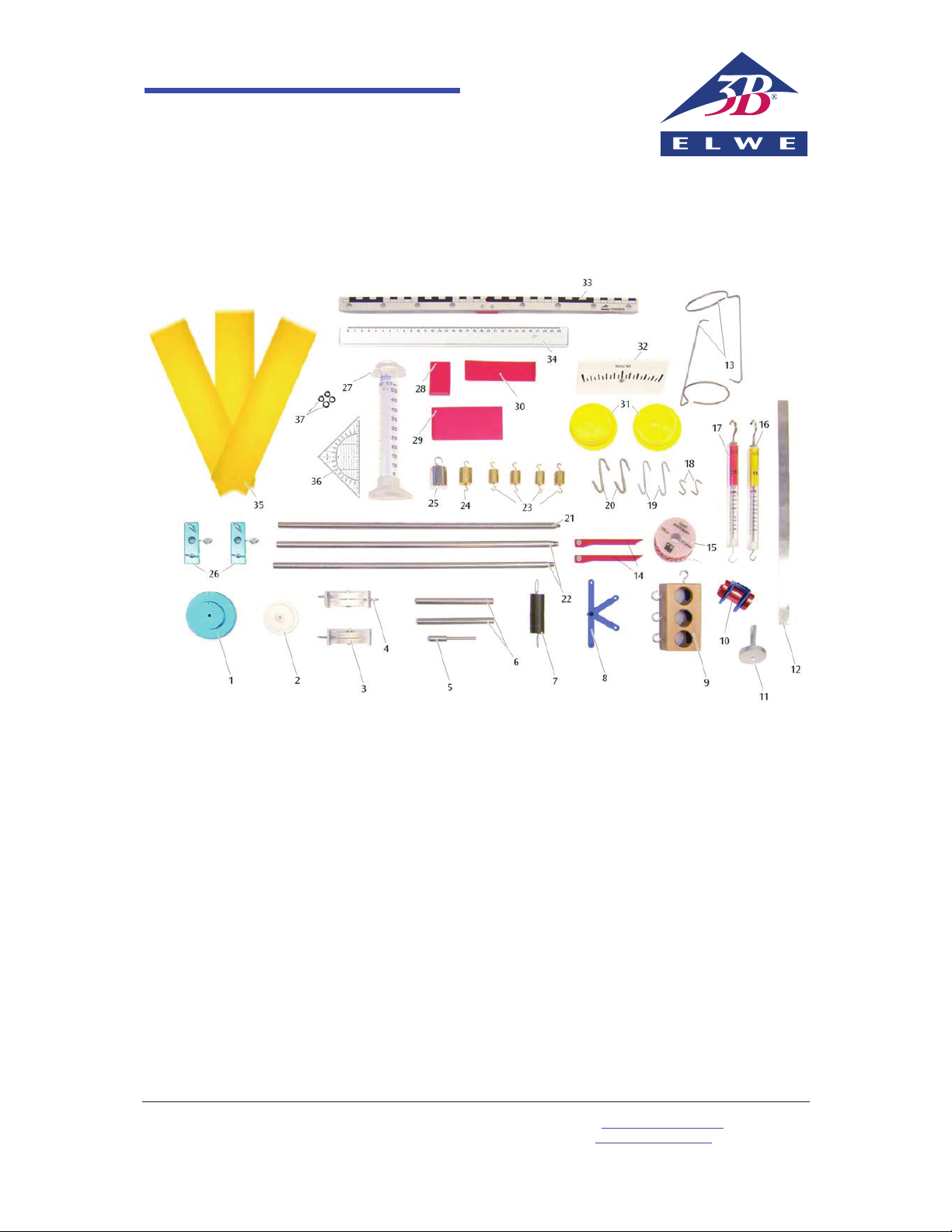
Contents
1 1 Multiple pulley
2 1 Plastic pulley, d = 40 mm
3 1 Block and tackle with two pulleys and one
hook
4 1 Block and tackle with two pulleys and two
hooks
5 1 Axle rod
6 2 Stand rods, short
7 1 Coil spring with 2 eyelets
8 1 Adjustable bracket
9 1 Body for friction and inertia experiments
10 1 Rolling pin with add-on weights
11 1 Magnetic base
12 1 Leaf spring, 330 mm
13 2 Hangers for scale pans
14 2 Pointers
15 1 Twine, 100 m
16 1 Dynamometer, 1 N
17 1 Dynamometer, 2 N
18 2 S-shaped hooks, 1 g
19 2 S-shaped hooks, 2 g
20 2 S-shaped hooks, 5 g
21 1 Stand rod with external thread
22 2 Stand rods with external and internal thread
23 4 Weights, 25 g
24 1 Weight, 50 g
25 1 Weight, 100 g
26 2 Double clamps
27 1 Measuring cylinder
28 1 Plastic strip, small
29 1 Plastic strip, large
30 1 Plastic strip, medium size
31 2 Weighing pans
32 1 Scale for balance
33 1 Beam balance
34 1 Ruler
35 3 Strips of velour paper
36 1 Set square
37 4 O-rings
Page 2
SEK Mechanics/Transformation of Forces
Work sheet
1
M201 First class levers
Exercise
x Investigate the conditions for equilibrium of a first-class lever.
Note: a body of mass 100 g gives rise to a force of approximately 1 N (rounded up) as a result of its weight.
Basic principles
A first-class lever is one in which forces act on either
side of the fulcrum D. The horizontal distances from
the fulcrum at which the forces act are d
1
and d2.
Carry out this experiment keeping the balance beam
horizontal so the distances d1 and d2 can be read off
directly from the beam itself.
F
2
F
1
D
d
2
d
1
Fig. 1 First-class lever
Equipment
From Mechanics (U8501000)
1 Stand rod with external and internal thread, 40 cm
1 Axle pin
1 Double clamp
1 Beam balance
2 O-rings
4 Weights, 25 g
1 Weight, 50 g
1 Weight, 100 g
1 Hook, 1 g
Additionally required
1 SEK base plate (U8408035)
25
25
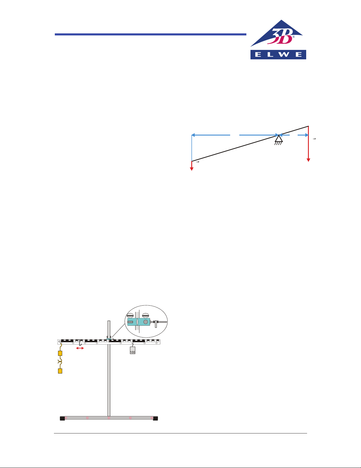
Set-up and procedure
1) Screw the stand rod into the central hole on the
base plate.
2) Attach the double clamp to the rod at a height
of about 30 cm and clamp the axle pin into it.
3) Insert an O-ring, the beam balance and a second O-ring over the metal axis (see Fig. 2).
4) Press both the O-rings as close as possible to the
beam balance, taking care to ensure that the
beam balance can still rotate freely.
5) Set the centre of the beam on the axle so that it
is balanced and horizontal. If necessary, the Sshaped hook weighing 1 g can be suspended
from the beam and shifted to a position that
ensures it does not tip (see Fig. 2).
6) Suspend various weights from the holes along
the balance beam. Set up the apparatus so that
weights F
1
and F2 and distances d1 and d2 match
those given in the table.
7) Perform experiments to determine the values
not specified in the table. In each case the balance beam should be in equilibrium, i.e. balanced.
8) Calculate the products
1 1
F d and 2 2F d , enter-
ing their values into the table as well.
Fig. 2 Set-up for first class lever
Page 3

Mechanics/M401 Work sheet SEK
2
Sub-experiment 1: Evaluation
Table 1: Length of pendulum d = 0.60 m
Weight of pendulum bob m in kg
Time in s for 10 oscillations
Period of oscillation T in s
0.025
15.6 1.56
0.050
15.4 1.54
0.075
15.5 1.55
Select the correct answer:
1) Compare the periods of oscillation. The period of oscillation T is
a) dependent on b) independent of
the pendulum mass m, all other things being equal
Correct: b)
Sub-experiment 2: Set-up and procedure
1) Use the set-up from sub-experiment 1, working with only one 25-g weight.
2) Enter the measurement you obtained in sub-experiment 1 for a pendulum length d = 60 cm into Table 2.
3) Change the length of the pendulum to d = 40 cm, measure the time for 10 oscillations and enter the value
into Table 2.
4) Repeat the measurement for the other lengths given in Table 2, entering your results into Table 2.
5) In each case, calculate the period of oscillation T in seconds and T² in s², entering the values into Table 2.
6) Plot the values in a graph of T² against d and draw a straight line through all the points and the origin.
Sub-experiment 2: Evaluation
Table 2: Mass of pendulum bob m = 0.025 kg
Length of
pendulum d in m
Number of
oscillations N
Time in s for
N oscillations
Period of oscillation T
in s
T² in s²
0.60 10
15.5 1.55 2.40
0.40 10
12.7 1.27 1.62
0.20 10
9.0 0.90 0.81
0.15 20
15.6 0.78 0.61
0.10 20
12.6 0.63 0.38
0.05 20
9.0 0.45 0.20
 Loading...