

Page 1
SEK Electricity U8506000
Elwe Didactic GmbH • Steinfelsstr. 6 • 08248 Klingenthal • Germany • www.elwedidactic.com
3B Scientific GmbH • Rudorffweg 8 • 21031 Hamburg • Germany • www.3bscientific.com
Subject to technical amendments
© Copyright 2010 3B Scientific GmbH
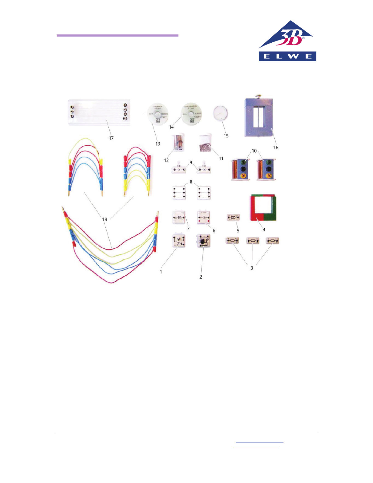
Contents
1 1 Switch (plug-in component)
2 1 Potentiometer (plug-in component)
3 1 Set of resistors, 33 :, 47 :, 1 k: (plug-in
components)
4 1 Horseshoe magnet and 1 bar magnet
5 1 NTC-resistor (plug-in component)
6 1 Electrolytic capacitor (plug-in component)
7 1 Capacitor (plug-in component)
8 2 Current branches (plug-in components)
9 2 Lamp sockets, E10 (plug-in components),
and 2 light bulbs
10 2 Coils
11 50 g of iron filings
12 1 Storage box with 1 set of threads with
washer, 2 threaded bushes, 2 threaded pins,
2 paper clips, 2 aluminium electrodes, con-
stantan wire
13 50 m of iron wire
14 50 m of chrome/nickel wire
15 1 Tea candle
16 1 Transformer core
17 1 Resistor board
18 1 Set of experiment leads
Page 2
SEK Electricity/Electric Current
Work sheet
1
E105 Electric current in circuits with no branches
Exercise
x Investigate current at various points in an electric circuit with no branches.
Equipment
From SEK Electricity and Magnetism (U8506000)
1 Resistor, 33 :
1 Resistor, 47 :
1 Switch
Experiment leads
Additionally required
1 SEK base plate (U8408035)
1 SEK power supply (U8498030)
1 ESCOLA 2 multimeter (U8531171)
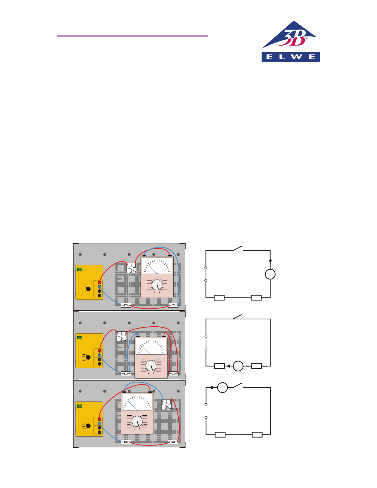
Set-up and procedure
1) Assemble a circuit as shown in Fig. 1a.
2) Set the rotary switch on the power supply to 6
V.
3) Set the ammeter to 3000 mA.
4) Have the circuit checked before you turn it on.
5) Turn on the power supply.
6) Close the switch and switch the ammeter back
step by step to the best measuring range I
1
. En-
ter your measurement into the table.
7) Measure the current values I2 and I3 by inserting
the ammeter at different points of the circuit,
according to the sketches in Fig. 1b and Fig. 1c.
Enter those values into the table.
8) Set the rotary switch of the power supply to 3 V
and repeat the whole experiment, entering the
results into the table.
9) Once the experiment is complete, turn the
power supply off.
a)
+
–
6 V
R
1
R
2
A
I
1
0 1
AC
DC
+
-
1,5 V
3 V
4,5 V
6 V
3000
3000
1000
100
10
1
mA =mA ~
V ~ V =
10
3
1
0,3
10
3
1
0,3
1000
100
10
1
+
–
6 V
A
I
2
R
1
R
2
0 1
AC
DC
+
-
1,5 V
3 V
4,5 V
6 V
b)
30003000
1000
100
10
1
mA =mA ~
V ~ V =
10
3
1
0,3
10
3
1
0,3
1000
100
10
1
+
–
6 V
A
I
3
R
1
R
2
0 1
AC
DC
+
-
1,5 V
3 V
4,5 V
6 V
c)
30003000
1000
100
10
1
mA =mA ~
V ~ V =
10
3
1
0,3
10
3
1
0,3
1000
100
10
1
3030
30 30
3030
Fig. 1
Page 3

Electricity/E506 Work sheet SEK
2
Sub-experiment 2:
Set-up and procedure
1) Connect the coil with a tap at 200 windings in
series with the first one and assemble a circuit
as in Fig. 2.
2) Set the power supply to operate with direct
current (DC) and turn the knob to 6 V.
3) Set the voltmeter to 1000 mA=.
4) Insert the yoke into the coil with 200 windings.
5) Turn on the power supply
6) Lift up the coil and yoke, observe the quantity
of iron filings that is lifted up and read off the
current. Enter the measured current and an estimate of the amount of iron filings lifted up
into Table 2.
7) Turn off the power supply, insert the core into
the coil with 800 windings and repeat the experiment. Enter the results into Table 2.
8) Turn off the power supply when the experiment
is finished.
6 V
+
–
A
N N = 200 = 800
Fig. 2 Set-up for Sub-experiment 2
Sub-experiment 2: Evaluation
Table 2:
I in mA
Number of
windings N
Amount of fil-
ings lifted
580 200 Few
580 800 Many
Complete the following:
1) If the current, the length of the coil and the
material inside the coil all remain the same,
the larger the number of windings, the
greater
the force in the magnetic field of the coil.
Sub-experiment 3:
Set-up and procedure
1) Use the same set-up as in sub-experiment 1
using the coil with 800 windings and no yoke
(see Fig. 3a).
2) Set the knob on the power supply to 6 V and
turn it on.
3) Lift up the coil, observe the amount of filings it
lifts and enter the result into Table 3.
4) Insert the core into the coil and repeat the
experiment (see Fig. 3b).
5) Turn off the power supply when the experiment
is finished.
6 V
+
–
A
a)
b)
N = 800
Fig. 3 Set-up for sub-experiment 3
Sub-experiment 3: Evaluation
Table 3:
Number of
windings N
Inside coil
Amount of
filings lifted
800 Air Few
800 Core Many
Complete the following:
If the current, the number of windings and the
length of the coil all remain the same, an iron core
inside the coil causes the forces in the magnetic
field of the coil to
increase
.
Note:
The force F exerted by a magnet is proportional to
the magnetic flux density
0 r
N
B µ µ I
d
,
where
µ0 = magnetic field constant (permeability of free
space), µr = relative permeability, I = current, N =
number of windings, d = length of coil. In our experiment we have shown that
B
v
I, B v N and B vPr.
 Loading...