

Page 1
Wireless Security System
2GIG-CNTRL2
Z-Wave Home Services
Operation &
User’s Guide
Page 2

The Go!Control Security System
Congratulations on your ownership of an Go!Control Security System!
This wireless system offers protection for your property against burglary,
protection for yourself and family with 24-hour emergency monitoring, and
optionally fi re and carbon monoxide detection for your home.
With the system’s built-in Z-Wave® home automation capability, you can
control your Z-Wave® enabled household lights and appliances from the
Control Panel or from a portable Z-Wave remote controller.
An exciting feature of the Go!Control Security System is the capability to
remotely control your Z-Wave® network of devices from your own computer
using a Web browser over the Internet. This provides you with home
automation control from anywhere in the world... even through your Web
enabled cell phone or PDA! (Web remote control is an optional feature, check
with your security professional for availability with your system.)
Page 3

Home Control Network Overview
The Z-Wave Network . . . . . . . . . . . . . . . 2
Home Services Access
Home Services Button . . . . . . . . . . . . . . 3
Device Management . . . . . . . . . . . . . . . . 3
Toolbox . . . . . . . . . . . . . . . . . . . . . . . . . . . 3
Network Setup
Adding Devices . . . . . . . . . . . . . . . . . . . . 4
Naming Devices . . . . . . . . . . . . . . . . . . . . 5
Basic Operation
Binary Switches . . . . . . . . . . . . . . . . . . . . 6
Multi-level Switches . . . . . . . . . . . . . . . . 7
Viewing Thermostats . . . . . . . . . . . . . . . 8
Controlling Thermostats . . . . . . . . . . . . . 9
Setting the Mode . . . . . . . . . . . . . . . . . 9
Setting the Temperature . . . . . . . . . . . 9
Setting the Fan Mode . . . . . . . . . . . . . . 9
Scenes & Rules
Controlling Multiple Devices . . . . . . . . 10
Creating Scenes . . . . . . . . . . . . . . . . . . 10
Z-Wave Switches . . . . . . . . . . . . . . . . 10
Z-Wave Thermostats . . . . . . . . . . . . . 10
Editing Scenes . . . . . . . . . . . . . . . . . . . . 11
Changing a Device’s Action . . . . . . . 11
Removing a Device’s Action . . . . . . . 11
Renaming a Scene . . . . . . . . . . . . . . . 11
Running Scenes . . . . . . . . . . . . . . . . . . . 12
Deleting Scenes . . . . . . . . . . . . . . . . . . . 12
Triggering Devices from Events . . . . . 13
Creating Rules . . . . . . . . . . . . . . . . . . . . 13
Editing Rules . . . . . . . . . . . . . . . . . . . . . . 14
Changing a Rule’s Action . . . . . . . . . . 14
Deleting Rules . . . . . . . . . . . . . . . . . . . . 14
Network Maintenance
Removing Devices . . . . . . . . . . . . . . . . . 15
Network Diagnostics . . . . . . . . . . . . . . 16
Checking the Network . . . . . . . . . . . . 16
Table of Contents
Advanced Setup
Advanced Toolbox . . . . . . . . . . . . . . . . . 17
Learn Controller . . . . . . . . . . . . . . . . . 17
Reset Controller . . . . . . . . . . . . . . . . . 17
View Controllers . . . . . . . . . . . . . . . . . 18
View All Devices . . . . . . . . . . . . . . . . . 18
Rediscover Network . . . . . . . . . . . . . . 19
Index . . . . . . . . . . . . . . . . . . . . . . . . . . . . . . 20
Important Information
Limited Warranty . . . . . . . . . . . . . . . . . . 21
FCC Regulatory Information . . . . . . . . . 21
IC Regulatory Information . . . . . . . . . . 21
Radio Compatibility . . . . . . . . . . . . . . . . 21
1
Page 4
Home Control Network Overview
The Z-Wave Network
Z-Wave® is “interoperable, two-way RF mesh networking technology”. In
plain English, Z-Wave® allows you to remotely control Z-Wave® enabled
devices in your home.
its subsidiaries.
Z-Wave enabled devices are remote control modules that lights or appliances
plug into or accessories with built-in Z-Wave capabilities that are designed to
work with all other Z-Wave enabled devices in a home control network. Each
module can act as a wireless “ repeater” that extends the range of the system
and insures that commands intended for another device in the network are
received.
The wireless range of Z-Wave devices have a standard, open-air, line-of-sight
distance of 65 feet. The actual performance in a home will depend on the
type on construction, amount of metal between devices, and the number of
Z-Wave devices that are repeating the wireless signals.
Beyond simple controlling of a single device, multiple device control
commands can be assigned using a “Scene”. A Scene can be run on its own,
or “ Rules” can be assigned to trigger a Scene after a Control Panel “ event”
such as arming your system or when an alarm occurs.
The Go!Control Security System’s Z-Wave Home Services has been designed
to operate with Z-Wave certifi ed binary (on/off) switches, multi-level (dimmer)
switches, thermostats, and portable controllers available from a variety of
equipment manufacturers.
Z-Wave is a registered trademark of Zensys Inc. and/or
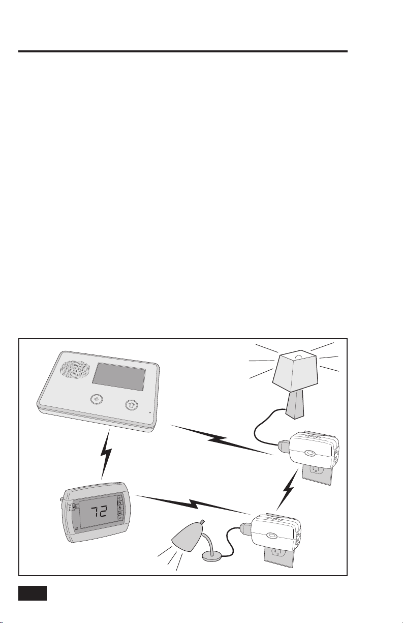
CONTROL
PANEL
WIRELESS
NETWORK
Z-WAVE
THERMOSTAT
THE Z-WAVE NETWORK AUTOMATICALLY
ADJUSTS THE NETWORK SIGNAL PATHS
DEPENDING ON SIGNAL CONDITIONS
SIGNALS
2
NETWORK SIGNALS TRAVEL
BETWEEN THE CONTROL
PANEL AND Z-WAVE DEVICES
NETWORK SIGNALS ALSO
TRAVEL DIRECTLY
BETWEEN Z-WAVE DEVICES
Typical Z-Wave Network
Z-WAVE
SWITCHES
Page 5
Home Services Access
Home Services Button
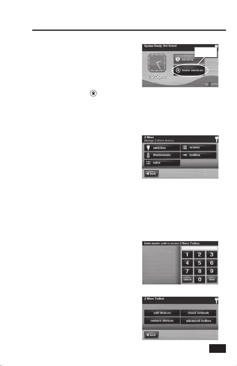
Home Services are accessed through the
system’s Home Screen. The Home Screen
shows the system status with icons to indicate
system conditions. It also displays the time
and date. The Home Screen displays the
SECURITY and HOME SERVICES buttons.
The Home Screen is normally displayed when
the system is disarmed. If it is not currently
being displayed, pressing the button on the
Control Panel will display the Home Screen.
Device Management
Setup and control of Z-Wave devices is accessed
by pressing the HOME SERVICES button and
using the Manage Z-Wave Devices Screen.
This screen displays buttons for Switches,
Thermostats, Rules, Scenes, and access to
the Z-Wave toolbox (Some Home Services
buttons may or may not display depending
on options selected by your Installer).
• The SWITCHES button will display
the currently included binary
and multi-level switches.
• The THERMOSTATS button will display
the currently included thermostat devices.
• The RULES button (if enabled) will
display the currently programmed
Rules that run Scenes after events.
• The SCENES button will display
currently programmed Scenes
that run device actions.
• The TOOLBOX button allows access to
the Z-Wave toolbox for setup of devices
(requires entry of the Master User Code).
Home Services
button
The Home Screen
Manage Z-Wave Devices Screen
Toolbox
Z-Wave setup is performed using the Toolbox.
Access the Toolbox using the following steps.
1. From the Manage Z-Wave Devices Screen, press
the TOOLBOX button.
2. Enter the Master User Code. Only the Master
User Code (or the Installer Code) can be used to
access the Z-Wave Toolbox.
✓ NOTE: Some Z-Wave display screens will
time-out after 30 seconds of inactivity and
the system will return to the Home Screen.
Master Code Entry Screen
Z-Wave Toolbox Screen
3
Page 6
Network Setup
Adding Devices
Before a device will work in the home control
network, it must be added (also called included)
into the network.
To add one or more switch or thermostat
devices into the network, use the following
steps:
1. Install the Z-Wave Device as directed by the
device’s instructions. If it is a lamp or appliance
module, connect the lamp or load to the module
and be sure the power switch on the lamp or
load is ON.
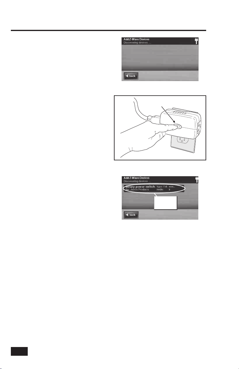
2. From the Toolbox Screen, press the ADD
DEVICES button. The Control Panel will display
“Discovering devices” and wait for a signal from
a device.
3. Press and quickly release the program button
on the device. (This button may also be called
“bind”, “learn”, or may not be labeled.)
4. When the device is discovered, the display will
show its kind, type, manufacturer, and network
node information assigned to the device.
5. Repeat Steps 3 and 4 for any additional devices
that need to be added to the network at this
time.
6. Press BACK when fi nished.
If additional Z-Wave compatible devices are
purchased, and your home control network
expands, these steps can be used at any time
to add additional devices.
Devices can only be included once in the
network. The system will not allow a device to
be added multiple times to the same network.
Add Z-Wave Devices Screen
PRESS Z-WAVE
DEVICE BUTTON
Pressing the Device’s Programming Button
New device
shows on
screen
Added Devices Shown
4
Page 7
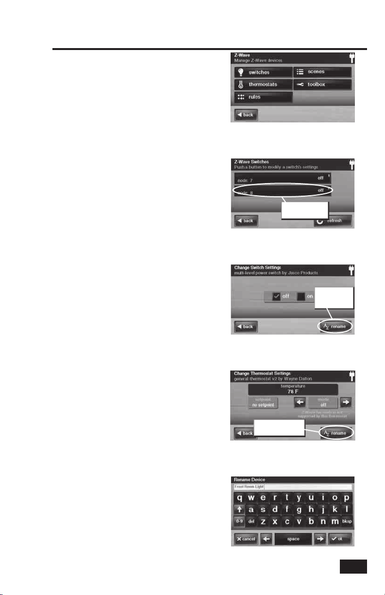
Naming Devices
Devices in the home control network can be
named to make it easy to identify the individual
lamp or appliance being controlled. The custom
name will show on the Control Panel’s display.
To name each installed switch or thermostat
device, use the following steps:
1. From the Manage Z-Wave Devices Screen, press
the SWITCHES or THERMOSTATS button.
2. A list of installed devices will display. If there
are more than three devices, use the ↑ or ↓
arrows to scroll the list.
3. Press the display where the device is listed
to display the current switch settings for the
device.
4. Press the RENAME button to display the
alphanumeric keyboard used to name the device.
5. Use the alphanumeric keyboard to assign a
name (up to 40 characters) to the device.
• Use the ↑ arrow key to shift
to capital letters.
• Use the ↓ arrow key to shift
to lower case letters.
• Press the 0-9 key to access numeric
and symbol characters.
• Press the a-z key to access
alphabetic characters.
• Use the DEL key to delete characters to the
right of the cursor or delete highlighted text.
• Use the BKSP key to delete characters
to the right of the cursor.
• Use the ← or → arrows to move
the cursor along the text.
6. Press OK when you are fi nished naming the
device.
7. Press BACK.
8. Repeat Steps 2 through 7 to name additional
devices.
9. Press BACK when fi nished.
Network Setup
Manage Z-Wave Devices Screen
Push device button
to rename
Installed Devices Shown
Push RENAME
button to
rename device
Switch Settings Display
Push RENAME button
to rename device
Thermostat Settings Display
Alphanumeric Keyboard Display
5
Page 8
Basic Operation
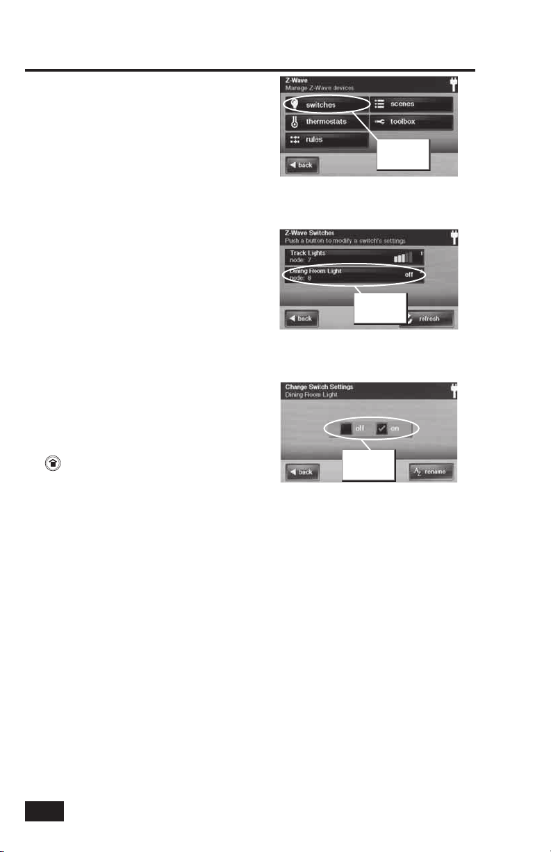
Binary Switches
Binary switch modules can be turned ON or
OFF. They cannot be set to in-between levels as
multi-level (dimmer) switch modules can.
To control a binary switch module, use the
following steps:
1. From the Home Screen press the HOME
SERVICES button.
2. From the Manage Z-Wave Devices Screen, press
the SWITCHES button.
3. A list of all installed switches will be displayed.
If there are more than three switches, use the ↑
or ↓ arrows to scroll the list. On the right side of
the switch button, binary switches will display
the current status of the switch (OFF or ON).
✓ NOTE: If the light or load is controlled at the
module while the Control Panel is showing
this display, press the REFRESH button to
update the display.
4. Press the display where the device is listed to
display the control buttons for the switch.
5. A check box indicates if the switch is OFF or ON.
Press the desired action for the switch (OFF or
ON). The lamp or load connected to the selected
binary switch module will follow your command.
6. Press the BACK button three times or the
button on the Control Panel to exit Home
Services.
Press
SWITCHES
button
Manage Z-Wave Devices Screen
Press device
button
Installed Switches Shown
Check box for
On or Off
Binary Switch Settings Display
6
Page 9

Multi-level Switches
Multi-level (dimmer) switch modules can be
turned ON, OFF, or set to 12 different dimming
levels.
To control a multi-level switch module, use the
following steps:
1. From the Home Screen press the HOME
SERVICES button.
2. From the Manage Z-Wave Devices Screen, press
the SWITCHES button.
3. A list of all installed switches will be displayed.
If there are more than three switches, use the ↑
or ↓ arrows to scroll the list. On the right side
of the switch button, multi-level switches will
display the current status of the switch (OFF or
bars showing the dimming level).
✓ NOTE: If the light is controlled at the
module while the Control Panel is showing
this display, press the REFRESH button to
update the display.
4. Press the display where the device is listed to
display the control buttons for the switch.
5. A check box indicates if the switch is OFF or
ON. If the switch is ON, the dimming level with
a number 1-12 will be shown below the check
boxes. Press the desired action for the switch;
OFF, ON, or adjust the dimming level using the
brightness buttons at each end of the dimming
level display. The lamp connected to the
selected multi-level switch module will follow
your command.
6. Press the BACK button three times or the
button on the Control Panel to exit Home
Services.
Basic Operation
Press
SWITCHES
button
Manage Z-Wave Devices Screen
Press device
button
Installed Switches Shown
Set device Off or On
Choose
Multi-level Switch Settings Display
dimmer level
7
Page 10

Basic Operation
Viewing Thermostats
Z-Wave compatible thermostats can be
controlled using the Home Services feature.
✓ NOTE: Several types of Z-Wave compatible
thermostats are available. Each type
provides different features. The Control
Panel’s Home Services Z-Wave control
will adjust to the thermostat model type,
but may not support all of the thermostat’s
features.
To view the thermostat control, use the
following steps:
1. From the Home Screen press the HOME
SERVICES button.
2. From the Manage Z-Wave Devices Screen, press
the THERMOSTATS button.
3. A list of all installed thermostats will be
displayed. If there are more than three
thermostats, use the ↑ or ↓ arrows to scroll the
list. On the bottom line of the thermostat button,
the fan status, current mode, and current room
temperature will be displayed.
✓ NOTE: If the controls at a thermostat are
adjusted while the Control Panel is showing
this display, press the REFRESH button to
update the display.
4. Press the display where the thermostat is listed
to display the control buttons for the thermostat.
5. The display shows the current temperature, the
thermostat setpoint, the thermostat mode, and
the fan mode (if supported).
✓ NOTE: Thermostats can be powered by the
HVAC system’s 24-volt AC power source
(called a C-wire or common wire system) or
be independently powered by batteries. To
save power, battery powered thermostats
send signals to the Control Panel at
intervals and may not update the Control
Panel’s display for a short period of time.
Press
THERMOSTATS
button
Manage Z-Wave Devices Screen
Press
thermostat’s
device button
Thermostats Screen
Current temperature
Current setpoint Current mode
Thermostat Settings Screen
8
Page 11

Controlling Thermostats
To adjust a thermostat’s settings, use the
following steps.
✓ NOTE: Several types of Z-Wave compatible
thermostats are available. Each type will
display different supported options.
Setting the Mode
1. Use the ← or → arrows on each side of the
mode display to choose between OFF, HEAT,
COOL, ENERGY SAVE HEAT, or ENERGY
SAVE COOL modes.
2. The thermostat will immediately switch to the
mode selected.
Setting the Temperature
1. Each thermostat mode (except OFF) can be set to
a temperature setpoint. Use the ↓ or ↑ arrows
to choose a temperature setpoint for the current
mode displayed.
2. The temperature setpoint is immediately
transmitted to the thermostat.
Setting the Fan Mode
If the thermostat supports Z-Wave fan control,
the fan mode selector will be displayed.
1. Use the ← or → arrows on each side of the fan
mode display to choose between MANUAL,
AUTO, MANUAL HIGH, MANUAL LOW,
AUTO HIGH, or AUTO LOW (NOTE: Only
modes supported by the thermostat will be
displayed).
2. The thermostat will set the system’s fan to the
selected mode. Manual modes are displayed in
yellow to indicate that the fan will remain on
and will not be automatically controlled by the
heating or cooling system.
Basic Operation
Thermostat Settings Screen
Use arrows to
select mode
Selecting a Mode
Use arrows to
select setpoint
Selecting a Setpoint
Use arrows to
select fan mode
Selecting the Fan Mode
9
Page 12

Scenes & Rules
Controlling Multiple Devices
Beyond simple controlling of a single device,
multiple device control commands can be
assigned using a “ Scene”. A Scene can be run
on its own, or “ Rules” can be assigned to trigger
a Scene after a Control Panel “event” such as
arming your system or when an alarm occurs.
Creating Scenes
Scenes are created by assigning one or more
device actions to the Scene. The multi-function
Scene can then be easily executed by pressing
the Scene’s RUN button.
To create a Scene, use the following steps:
1. From the Home Screen press the HOME
SERVICES button.
2. From the Manage Z-Wave Devices Screen, press
the SCENES button.
3. From the Z-Wave Scenes Screen press the ADD
SCENE button.
4. Use the alphanumeric keypad displayed to enter
a name for the new Scene. Press OK when
fi nished.
5. Press the ADD button.
6. Press Z-WAVE SWITCH or Z-WAVE
THERMOSTAT to add one of these device types
as an action to the Scene.
Press ADD SCENE
button
Z-Wave Scenes Screen
Press a device type
for the action
Create Action Screen
Choose a device, then
set the action
New Switch Action Screen
Z-Wave Switches
7A. Use the ← or → arrows to choose a switch
device (if there is more than one device), then
select an ON, OFF, or a dimming level for the
switch. Press OK.
Z-Wave Thermostats
7B. Use the ← or → arrows to choose a thermostat
device (if there is more than one device), then
select a mode, setpoint, and fan setting for the
thermostat. Press OK.
✓ NOTE: The device will not activate while
setting Steps 7A & 7B. The scene must be
“run” or triggered by an event with a “rule”.
8. The assigned action(s) for the Scene will be
displayed. Repeat Steps 5 through 7 to add
additional actions to the Scene. Press BACK
when fi nished.
✓ NOTE: Only one action per device can be
assigned per Scene.
9. Test the Scene by pressing RUN. A Scene
execution confi rmation screen will be displayed,
press OK.
10
Choose setpoints and
New Thermostat Action Screen
New Scene with Actions Screen
Scenes Screen with RUN Button
modes
Press RUN button to
run the scene
Page 13

Editing Scenes
Scenes can be edited to change a device’s
action, remove a device’s action, or rename the
Scene.
To edit a Scene, use the following steps.
Scenes & Rules
Press scene button
Changing a Device’s Action
1. From the Home Screen press the HOME
SERVICES button.
2. From the Manage Z-Wave Devices Screen, press
the SCENES button.
3. A list of programmed Scenes will be displayed.
Press the name of the Scene to edit.
4. Press the desired device’s button to select it.
5. Change the confi guration for the device and
press OK, then press BACK.
6. Test the Scene by pressing the RUN button. A
Scene execution confi rmation screen will be
displayed, press OK.
Removing a Device’s Action
1. From the Home Screen press the HOME
SERVICES button.
2. From the Manage Z-Wave Devices Screen, press
the SCENES button.
3. A list of programmed Scenes will be displayed.
Press the name of the Scene to edit.
4. Press the desired device’s button to select it.
5. Press DELETE ACTION. A confi rmation screen
will be displayed, press DELETE ACTION to
confi rm, or CANCEL to quit without deleting.
Renaming a Scene
1. From the Home Screen press the HOME
SERVICES button.
2. From the Manage Z-Wave Devices Screen, press
the SCENES button.
3. A list of programmed Scenes will be displayed.
Press the name of the Scene to rename.
4. Press RENAME. Use the alphanumeric keypad
displayed to rename the Scene.
5. Press OK to confi rm the name change or
CANCEL to quit.
Scenes Screen with RUN Button
Press action to edit
Scene Action Screen
Press DELETE
ACTION button
Delete Actions Screen
Press RENAME
button
Scene Action Screen
11
Page 14

Scenes & Rules
Running Scenes
Scenes can be run by hand manually, or be
automatically run when triggered by a Rule.
To run a Scene manually, use the following
steps:
1. From the Home Screen press the HOME
SERVICES button.
2. From the Manage Z-Wave Devices Screen, press
the SCENES button.
3. A list of programmed Scenes will be displayed.
4. Press the RUN button next to the desired Scene.
5. A Scene execution confi rmation screen will be
displayed, press OK.
Deleting Scenes
Scenes can be deleted individually.
✓ NOTE: Deleting a Scene will also delete any
Rule associated with the Scene.
To delete a Scene, use the following steps.
1. From the Home Screen press the HOME
SERVICES button.
2. From the Manage Z-Wave Devices Screen, press
the SCENES button.
3. A list of programmed Scenes will be displayed.
Press the name of the Scene to delete.
4. Press DELETE. A confi rmation screen will be
displayed, press DELETE SCENE to confi rm, or
CANCEL to quit without deleting.
5. A Scene Deleted confi rmation screen will be
displayed, press OK.
Press ADD SCENE
button
RUN Button on Scenes Screen
Scene Executed Screen
Delete
scene
button
Scene Action Screen
12
Press to confi rm
Scene Delete Confi rmation Screen
Scene Deleted Screen
Page 15

Triggering Devices from Events
A Scene can be run on its own, or “ Rules” can
be assigned to trigger a Scene after a Control
Panel “event” such as arming your system or
when an alarm occurs.
Creating Rules
Rules are created by assigning a Scene to run
for an event that occurs.
To create a Rule, use the following steps:
1. From the Home Screen press the HOME
SERVICES button.
2. From the Manage Z-Wave Devices Screen, press
the RULES button.
3. From the Event Rules Screen press the ADD
RULE button.
4. Use the ← or → arrows to choose a system
event to trigger the Scene. The events available
are:
• System Armed Away
• System Armed Stay
• System Disarmed
• Exit Delay Started
• Entry Delay Started
• Fire or CO Alarm
• Alarm
• Audible Alarm
• Auxiliary Alarm
• Non-response Zone Opened
• Non-response Zone Closed
5. Use the ← or → arrows to choose a Scene to
run when the selected event occurs.
6. Press OK to create the Rule or CANCEL to quit.
7. Repeat Steps 3 through 6 to create additional
Rules, or press BACK to quit.
Scenes & Rules
Press RULES button
Manage Z-Wave Devices Screen
Press ADD RULE
button
Add Event Rules Screen
New Event Rules Screen
Use arrows to select an event
to trigger the scene
Selecting an Event
Use arrows to select a scene
that the event triggers
Selecting a Scene
New rule
Event Rules Screen Showing New Rule
13
Page 16

Scenes & Rules
Editing Rules
Rules can be edited to change an event that
triggers the Rule or to change the Scene that
the Rule runs.
Changing a Rule’s Action
To change a Rule’s action, use the following
steps:
1. From the Home Screen press the HOME
SERVICES button.
2. From the Manage Z-Wave Devices Screen, press
the RULES button.
3. A list of programmed Rules will be displayed.
Press the name of the Rule to edit.
4. Use the ← or → arrows to choose a system
event to trigger the Scene. The events available
are:
• System Armed Away
• System Armed Stay
• System Disarmed
• Exit Delay Started
• Entry Delay Started
• Fire or CO Alarm
• Alarm
• Audible Alarm
• Auxiliary Alarm
• Non-response Zone Opened
• Non-response Zone Closed
5. Use the ← or → arrows to choose a Scene to
run when the selected event occurs (the scene
can also be edited here by pressing the “Run this
Scene” button).
6. Press OK to change the Rule or CANCEL to quit.
Press rules
button
Manage Z-Wave Devices Screen
Push rule
button to edit
Event Rules Screen
Use arrows to select a different
event to trigger the scene
Editing the Selected Event
Deleting Rules
Rules can be deleted individually. To delete a
Rule, use the following steps:
1. From the Home Screen press the HOME
SERVICES button.
2. From the Manage Z-Wave Devices Screen, press
the RULES button.
3. A list of programmed Rules will be displayed.
Press the name of the Rule to delete.
4. Press DELETE RULE. A confi rmation screen will
be displayed, press DELETE RULE to confi rm, or
CANCEL to quit without deleting.
5. A Rule Deleted confi rmation screen will be
displayed, press OK.
14
Use arrows to select a different scene
that the event triggers
Editing the Selected Scene
Push to delete
a rule
Deleting a Rule
Page 17

Network Maintenance
Removing Devices
When a device will no longer be used in the
home control network, it should be removed
(also called excluded) from the network so the
system will not try to communicate with the
missing device.
To remove one or more devices from the
network, use the following steps:
1. From the Toolbox Screen, press the REMOVE
DEVICES button. The Control Panel will display
“Discovering devices” and wait for a signal from
a device.
2. Press and release the program button on the
device. (This button may also be called “bind”,
“learn”, or may not be labeled.)
3. When the device is discovered, the display will
show “A device has been removed from the
network...”.
4. Repeat Steps 2 and 3 for any additional devices
that need to be removed from the network at
this time.
5. Press BACK when fi nished.
These steps can be used at any time to remove
devices from the home control network.
Remove Z-Wave Devices Screen
PRESS Z-WAVE
DEVICE BUTTON
Pressing the Device’s Programming Button
Removed device
indication
Removed Devices Display
15
Page 18

Network Maintenance
Network Diagnostics
The Home Services Z-Wave network
periodically checks to determine if a network
device has become un-plugged, has failed, or
is missing.
The network can also be checked manually by
pressing the CHECK NETWORK button on the
Home Services Toolbox screen.
If there is a network issue, the HOME
SERVICES button on the Home Screen will
display as orange instead of blue.
The TOOLBOX button and the CHECK
NETWORK button will also display as orange
instead of blue if there is a network issue.
Use the following steps to correct a network
issue.
1. Press the orange HOME SERVICES button.
The Manage Home Automation screen will be
displayed.
2. The Z-Wave logo will be displayed, along with
the trouble alert icon. The trouble alert
icon displays a number in the upper right corner
that is the number of devices the network has
detected trouble with.
3. Press the trouble alert icon to display the
device(s) the network has detected trouble with.
4. Go to the displayed devices location(s) and
inspect for un-plugged or missing devices. Either
correct the devices installation, or remove the
device from the network using the following
steps. Press BACK to exit without making any
changes.
5. To remove a failed device, press the device’s
button on the Failed Devices Screen. Press
REMOVE FAILED DEVICE. A confi rmation
screen will be displayed, press OK.
Home Services
button turns
orange
Home Screen with Orange Button
Z-Wave
trouble icon
Trouble Alert Screen
Push device
button to
remove
Delete Failed Devices Screen
Checking the Network
The Z-Wave network can be checked manually
using the CHECK NETWORK button. Use the
following steps:
1. From the Z-Wave toolbox, press the CHECK
NETWORK button.
2. Wait while the system checks the network.
THIS MAY TAKE SEVERAL MINUTES.
3. Any new or failed network nodes will be
displayed.
16
Device Removed Confi rmation Screen
Checking Network Screen
Page 19

Advanced Toolbox
The Advanced Toolbox is used to add a
secondary controller, reset and view installed
controllers, view the currently installed network
devices, or rediscover the network devices.
On the Z-Wave Toolbox Screen, press
ADVANCED TOOLBOX to access the
Advanced Toolbox functions.
Learn Controller
The Control Panel can be added to an existing
Z-Wave network as a “ secondary” controller.
When the Control Panel acts as a secondary
controller, devices will only be able to
be added and removed by the primary
controller. Other than that, all functions are
available to either controller.
Use the following steps to add the Control
Panel as a secondary controller:
1. From the Advanced Toolbox Screen, press the
LEARN CONTROLLER button. The Control
Panel will display “Learning Z-Wave Controller”
and wait for a signal from the primary controller.
2. Press and release the include button on the
primary controller. (This button may also be
called “bind”, “learn”, or may not be labeled.)
3. A confi rmation screen will be displayed, press
OK.
Advanced Setup
Advanced Z-Wave Toolbox
Learn Controller Screen
Reset Controller
Resetting the controller will remove all Z-Wave
devices from the network and controller. The
network node information will also be reset.
Reset the controller only after removing all
the devices one at a time using the REMOVE
DEVICES button.
Use the following steps to reset the controller:
1. From the Advanced Toolbox Screen, press the
RESET CONTROLLER button.
2. A reset confi rmation screen will be displayed,
press RESET Z-WAVE CONTROLLER to
continue or CANCEL to exit.
3. A completion confi rmation screen will be
displayed, press OK.
To re-build the Z-Wave network, use the Add
Devices function.
Reset Controller Screen
17
Page 20

Advanced Setup
Advanced Toolbox (cont.)
View Controllers
The Control Panel can display each Z-Wave
controller programmed into the network.
Use the following steps to display the
controllers.
1. From the Advanced Toolbox Screen, press the
VIEW CONTROLLERS button.
2. Each programmed controller will be
displayed. Use the ↑ or ↓ arrows to scroll
the display if more than three controllers
are listed. The controller listings will show
the controller’s name, manufacturer, and
network node number.
3. Press BACK to quit.
View All Devices
Use the following steps to display all the
devices programmed into the network.
1. From the Advanced Toolbox Screen, press the
VIEW ALL DEVICES button.
2. Each programmed device will be displayed.
Use the ↑ or ↓ arrows to scroll the display
if more than three devices are listed. The
controller listings will show the device’s
name, type/id number, manufacturer, and
network node number.
3. Press BACK to quit.
View Controllers Screen
Z-Wave Devices Screen
18
Page 21

Advanced Toolbox (cont.)
Rediscover Network
During normal operation the network decides
the best path to route signals from one device
to another. If devices are moved to different
positions in the installation, it is recommended
to rediscover the network so the routing path
will be re-confi gured.
Use the following steps to rediscover the
network:
1. From the Advanced Toolbox Screen, press the
REDISCOVER NETWORK button. The Control
Panel will display “Rediscovering Z-Wave
devices”.
2. The system will pause, then return to the
Advanced Toolbox.
Advanced Setup
Rediscovering Network Screen
19
Page 22

Index
A
Adding devices 4
ADD RULE button 13
ADD SCENES button 10
Advanced setup 17, 18, 19
Advanced toolbox 17, 18, 19
ADVANCED TOOLBOX button 17
B
Basic operation 6, 7, 8, 9
Binary switches 2, 6
C
Changing a devices action 11
Changing a rules action 14
Checking the network 16
CHECK NETWORK button 16
Controlling multiple devices 10
Controlling thermostats 9
Creating rules 13
Creating scenes 10
D
DELETE ACTION button 11
DELETE RULE button 14
DELETE SCENE button 12
Deleting rules 14
Deleting scenes 12
Device management 3
E
Editing rules 14
Editing scenes 11
Event 2
F
FCC regulatory information 21
H
Home Services button 3
I
IC regulatory information 21
L
Learn Controller 17
LEARN CONTROLLER button 17
Limited warranty 21
M
Multi-level switches 2, 7
N
Naming devices 5
Network diagnostics 16
Network maintenance 15, 16
Network setup 4, 5
O
Orange buttons 16
R
Radio compatibility 21
Rediscover network 19
REDISCOVER NETWORK button 19
Refresh button 6
REFRESH button 7, 8
REMOVE DEVICES button 15, 17
REMOVE FAILED DEVICE button 16
Removing a device’s action 11
Removing devices 15
RENAME button 5, 11
Repeater 2
Reset controller 17
RESET CONTROLLER button 17
RESET Z-WAVE CONTROLLER button 17
Rules 2, 10, 13
RULES button 3, 13, 14
RUN button 10, 11, 12
Running scenes 12
S
Scene 2, 10, 13
Scenes and rules 10, 11, 12, 13, 14
SCENES button 3, 10, 11, 12
Screen timeout 3
Secondary controller 17
Setpoint 9
Switches button 6
SWITCHES button 3, 7
T
Thermostat fan mode 9
Thermostat mode 9
THERMOSTATS button 3, 8
Thermostat setpoint 8
Thermostat temperature 9
Toolbox 3
TOOLBOX button 3
Triggering devices from events 13
Trouble alert icon 16
U
Un-plugged device 16
V
View all devices 18
VIEW ALL DEVICES button 18
View controllers 18
VIEW CONTROLLERS button 18
Viewing thermostats 8
W
Warranty service 21
Z
Z-Wave devices 2
Z-Wave network 2
Z-Wave switches 10
Z-Wave thermostats 10
Z-Wave wireless range 2
20
Page 23

Important Information
Limited Warranty
This 2gig Technologies Inc. product is warranted against defects in material and workmanship for twelve (12) months. This
warranty extends only to wholesale customers who buy through 2gig Technologies Inc. authorized distribution channels.
2gig Technologies Inc. does not warrant this product to consumers. Consumers should inquire from their selling dealer as
to the nature of the dealer’s warranty, if any. There are no obligations or liabilities on the part of 2gig Technologies Inc.
for consequential damages arising out of or in connection with use or performance of this product or other indirect
damages with respect to loss of property, revenue, or profi t, or cost of removal, installation, or reinstallation. All
implied warranties, including implied warranties for merchantability and implied warranties for fi tness, are valid only until the
warranty expires. This 2gig Technologies Inc. Warranty is in lieu of all other warranties express or implied.
For warranty service call your local alarm installation and service professional at the contact information shown on the back cover
of this User’s Guide.
FCC Regulatory Information
This equipment generates and uses radio frequency energy and if not installed and used properly, that is, in strict accordance
with the manufacturer’s instructions, may cause interference to radio and television reception. It has been type tested and found
to comply with the limits for a Class B computing device in accordance with Part 15 of FCC Rules, which are designed to provide
reasonable protection against such interference in a residential installation. However, there is no guarantee that interference
will not occur in a particular installation. If this equipment does cause interference to radio or television reception, which can be
determined by turning the equipment off and on, the user is encouraged to try to correct the interference by one or more of the
following measures:
• Relocate the Console away from the TV/radio receiver.
• Plug the Console into a different wall outlet so that the Console is on a different branch circuit.
• Re-orient the TV/radio antenna.
• If necessary, the user should consult the dealer or an experienced radio/television technician for additional suggestions.
IC Regulatory Information
This Class B digital apparatus meets all requirements of the Canadian Interference Causing Equipment Regulations. Operation is
subject to the following two conditions: (1) this device may not cause harmful interference, and (2) this device must accept any
interference received, including interference that may cause undesired operation of the device.
Cet appareillage numérique de la classe B répond a toutes les exigences de l’interferérence canadienne causant des règlements
d’équipment. L’opération est sujette aux deux conditions suivantes: (1) ce dispositif peut ne pas causer l’interférence nocive, et
(2) ce dispositif doit accepter n’importe quelle interférence reçue, y compris l’interférence qui peut causer l’opération peu désirée.
WARNING: Changes or modifications to this receiver not expressly approved by 2gig Technologies Inc. could void the user’s
authority to operate this equipment.
Radio Compatibility
Z-Wave home control networks are designed to work properly alongside 802.11 wireless computer networks, Bluetooth and other
2.4 GHz or 5.8 GHz devices. Some baby cams, wireless video devices and older cordless phones using the 900 MHz frequency
range may cause interference and limit the Z-Wave functionality.
21
Page 24

YOUR LOCAL ALARM INSTALLATION AND SERVICE PROFESSIONAL:
Copyright © 2010 230786 A
 Loading...