

Page 1

TS1-E ADDENDUM - LINEAR P/N: 232686 X3 - INK: BLACK - MATERIAL: 20 LB. MEAD BOND WITH 80 LB. WHITE COATED COVER - SIZE: FLAT 17.000” x 11.000”, FINISH 8.500” X 11.000” - SCALE: 1-1 - FOLDING: 1 FOLD VERTICAL - FINISH: 3-HOLE STD. DRILL
PRINTER’S INSTRUCTIONS:
Release 1.8 and 2GIG-TS1
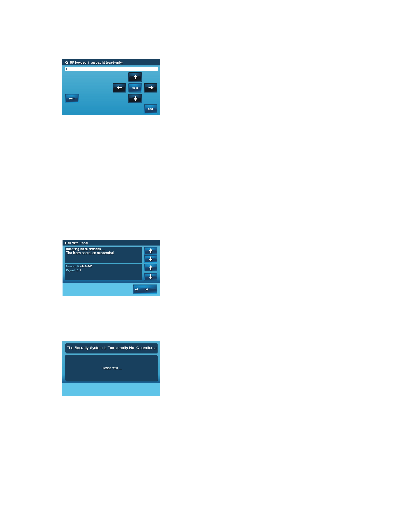
(4) From the CP1-900, enter the Installer Tool Box and select
System Confi guration from the CP1-900. Select the Go To
button and enter 04 to go to question 4. The CP1-900 will
display Q4: select RF keypad # (1 to 4).
Technical Support
855-2GIGTECH / 855-244-4832
www.2gig.com
THE 2GIG-TS1
The new Wireless Touch Screen Keypad, 2GIG-TS1, (referred to as TS1 in this
document) is unlike any other wireless keypad you have seen before. It not only
offers the functionality of a system keypad but also extends all user control of the
2GIG Go!Control panel to other locations in your home. Using the TS1, you can
control your lights, thermostat and door locks and see the status of every zone in
your home using the exact same and familiar interface found on the Go!Control
panel. The TS1 truly is an industry fi rst in offering outstanding two-way interaction
with your 2GIG security and home automation system.
Prerequisites:
• You must have the Go!Control panel (2GIG-CP1-900, referred
to in this document as CP1-900) with the 900 MHz Transceiver
installed in order to use the TS1. The 900 MHz Transceiver
(2GIG-XCVR2) is the communication module that incorporates
a 345 MHz receiver and a 900 MHz transceiver.
• It is assumed that you have general familiarity with 2GIG’s Go!Control
panel programming and the software features currently included in
software release 1.6. If additional information is required in these areas,
please download the installation guides found on www.2gig.com.
LEARNING/PAIRING THE 2GIG-TS1
To learn or pair a TS1 with a CP1-900 panel, you must follow the
steps below:
(1) Make sure that your CP1-900 panel is powered and
operational. Use the supplied AC adapter and confi rm that
the adapter is connected with the correct polarity. Note that
a Go!Control panel without the 900 MHz Transceiver will not
communicate with the TS1.
(2) Make sure the TS1 has power from the supplied AC
transformer. Connect the AC adapter that was supplied with
the TS1 to the TS1. Confi rm that the wires are connected
using the correct polarity.
(3) The TS1 should power up and the following message should
be visible on the display; This Device is Not Paired with a
Control Panel. See example below. Follow the rest of these
steps to correctly pair the TS1 with the CP1-900.
(5) Select the RF Keypad number to assign to the TS1. Use
the right arrow button to select the RF Keypad number (1-
4). After selecting the RF Keypad number, press the down
arrow to start confi guring the specifi c parameters for the RF
Keypad you have selected.
(6) Mark the RF Keypad number selected as “used” by pressing
the right arrow to toggle the setting on the fi rst question or by
pressing the number 1 on the keypad. Press the down arrow
key to advance to the next option.
(7) Set RF Keypad Equipment Code to “(1059) 2GIG-TS1
wireless touchscreen keypad”. By pressing the down arrow,
you can select the RF Keypad Equipment Code option. When
the RF Keypad Equipment Code option is selected, pressing
the right or left arrow will toggle through the options. Stop
when the “(1059) 2GIG-TS1 wireless touchscreen keypad”
option is displayed. Press the down arrow key to advance to
the next option.
Page 2
(8) “Learn” the TS1 into the CP1-900 panel. After pressing the
down arrow to select the TS1 as described in the previous
step, you will see the option to “learn” or pair the TS1 to the
CP1-900 panel.
Press the “Learn” button on the CP1-900 panel and the “pair
with panel” button on the TS1 to initiate the learning process.
The screen will display “Pair with TS1. Initiating learning
process.” Both the TS1 and CP1-900 panel will display “The
learn operation succeeded” when the learning is complete.
a. The CP1-900 panel will also display “Type: TS1 Wireless
Keypad ID#: X” where X is the RF Keypad number
confi gured for the TS1.
b. The TS1 will display “Network ID: xxxx” where xxxx is
a unique hexadecimal number and a keypad id. The
hexadecimal number is a unique number associated
with the CP1-900 panel you are using. The keypad id
indicates the keypad you are learning into the CP1-900
panel.
c. Press the OK button on both the CP1-900 and the TS1
to complete the learning process.
(9) Press the down arrow to exit the learning menu after
successfully learning the TS1. NOTE: The TS1 will display
a message indicating that the security system is temporarily
inoperable. The TS1 will remain in this state while the
CP1-900 panel is in system confi guration (programming)
mode.
(10) Repeat the above steps to confi gure additional TS1s.
(11) Follow the subsequent confi guration screens to complete
system confi guration as needed, except as noted below.
These confi guration screens are the same as those used
in previous releases. Please refer to current installation
documentation as needed.
(12) Exit the confi guration by pressing the End button and saving
your changes.
REMOVING A 2GIG-TS1
To remove a TS1 from a CP1-900’s panel confi guration you must
follow the steps below:
(1) From the CP1-900, enter the Installer Toolbox and select
System Confi guration. Select the Go To button and enter
04 to go to question 4. The CP1-900 will display Q4: select
RF keypad # (1 to 4). Select the confi gured TS1 you wish to
remove and press the down arrow.
(2) Mark the RF Keypad number selected as “unused” by
pressing the right arrow to toggle the setting on the fi rst
question. Press the down arrow key to advance to the next
option. Repeat steps 10, 11 and 12 from above.
(3) In order to reset the TS1 to defaults so it may be used again
on another panel or learned as a different keypad you must
do the following;
a. Remove the power from the TS1
b. When powering up the TS1 hold both the Emergency and
the Home buttons down simultaneously until they light
up. When both buttons light up, the TS1 has successfully
been reset to all default settings. The TS1 will display the
message, “This Device is Not Paired with a Control
Panel.”
Additional New Features
Available in Software Release 1.8
Enhancements to the Installer Toolbox
1. Q-13 Modifi ed
Select 2-way voice, now includes an option to “stay on line” to
enable two-way voice during fi re and CO alarms.
Q-13 Select 2-way voice (0-2)
DEFAULT: Stay on line (1)
The Control Panel supports 2-way voice communications between
the subscriber and the Central Station operator over the telephone
line or the GSM cellular radio (if installed) after an alarm has been
reported.
• The default (1) allows 2-way audio over the telephone line or
GSM radio.
• Selecting (2) allows 2-way audio over the telephone line or
GSM radio during fi re and CO alarms.
• To turn off the 2-way audio feature, select disabled (0).
• When the Control Panel connects with the operator, it will beep
once per second (every six seconds with a GSM connection).
The beep alternates between two tones and indicates the panel
is waiting for a session command. If the operator fails to issue
a command within one minute (three minutes with a GSM
connection), the call is terminated. Once the operator presses
a command option, the beeps will stop and a 5-minute audio
session will start (3-minute audio session with a GSM connection).
When 2-way voice communications have been established, the
Central Station operator can use the following telephone keys
to control the communications. Each time the operator uses a
command key, the session is extended for fi ve additional minutes
(three minutes with a GSM connection). During the last minute of
communications, the system will beep twice every 15 seconds to
indicate that time is running out.
• Pressing 1 enables Talk Mode one-way communication from the
CS to the Premises and allows the operator to talk.
• Pressing 2 enables VOX Mode two-way communications from the
CS to the premises.
• Pressing 3 enables Listen Mode one-way communication from
the premises to the CS.
Page 3

• Pressing 7 extends the session fi ve minutes without changing the
mode of operation.
• Pressing 9 causes the audio session to end and terminates the
call.
2. Q-30 Removed
Previously the installer could select the number of hours (0-24) as
an offset for when the periodic/automatic test report would be sent.
Now the periodic/automatic test report is randomized by the CP1900 over a 24-hour period.
✓ NOTE: See Q-29 for information on setting the automatic test
report period.
3. Q-39 Modifi ed
If enabled (default) the random AC loss report time is now
randomized over a 45-minute period, rather than a 4-hour period.
Q-39 Select random AC loss report time (0-1)
DEFAULT: Enabled (1)
This feature allows the system to report AC power loss and AC
power restore at a random time of up to forty-fi ve (45) minutes after
the event occurs. This helps to reduce Central Station congestion
due to a widespread power outage affecting many Control Panels
at once. The random AC power status report timer is triggered
based on the time set by Q-38.
• The default (1) allows random timed AC power reports.
• To turn off random timed AC power reports, select disabled (0).
4. Q-84, Q-85 and Q-86 Added
Q-84 Select services requires the master code (0-1)
DEFAULT: Disabled (0)
The Services button can be confi gured to require the use of the
master code to access Services.
• The default (0) disables the requirement for the master code to
access the Services menu.
• To require the use of the master code to access the Services
menu, select enabled (1).
When enabled then the master code is required to access the
Services and the Z-wave device confi gurations. This keeps
unauthorized users from being able to change Z-wave settings,
such as temperature, lights and locks.
Q-85 Select Z-Wave Toolbox menu requires the master code
(0-1)
DEFAULT: Disabled (0)
The Z-Wave Toolbox menu can be set to require the use of the
master code rather than the Installer code. By default, the Installer
code is required for users to access the Z-Wave Toolbox.
• The default (0) disable requires the use of the Installer code to
access the Toolbox menu and all of its features, including the
Advanced Toolbox.
• To require the use of the master code to access the Toolbox
menu, select enabled (1).
When enabled (1) the Installer code will be required to access the
Advanced Toolbox menu. This prevents end users from adding or
removing Z-Wave devices.
Q-86 Select disable siren after two-way audio (0-1)
DEFAULT: Disabled (0)
• The default (0) disable will cause the siren to resume after twoway audio (if bell cut off has not expired).
• Enable (1) will cause the siren to shut off after a two-way audio
session.
This setting enhances system operation in PERS applications and
also provides the dealer with the option of the siren sounding until
the bell cut off or to the end of a two-way-voice session.
5. User Interface Enhancements
(1) The speaker icon found to the right of the Security button on
the main menu allows the user to silence all CP1-900 panel
sounds. When pressing this button the user is able to silently
arm or disarm the CP1-900 and any confi gured TS1 during
the current arming or disarming process. The setting is reset
after the current arming or disarming process is completed.
This feature provides the ability to silently arm or disarm the
system without disturbing anyone in the house.
(2) The starburst symbol next to the Services button provides a
quick and easy way to turn off the LCD screen on the CP1-
900. When pressing this button on the TS1, the LCD and the
LEDs around the Home and Emergency buttons will turn off.
This feature is perfect for bedrooms or other areas where
you may not want the excess light from the CP1-900 or TS1
to light up the room during the night. To restore the display,
simple touch the LCD screen or one of the buttons on the
CP1-900 or TS1.
(3) Users are now able to arm their system when an interior
zone is active. If a PIR detects a user’s motion, the system
will still be ready to arm enabling a user to arm their system
without having to bypass the PIR’s interior zone or to wait
until the PIR’s state is restored.
NOTE: Bypass Sensor screen does not appear for interior zones
when ARMING AWAY. Any contact set as interior that is not
closed will cause the system to go into alarm when the exit
timer expires.
(4) New larger icons and layout under security and menu.
(5) New icons when arming for No Entry Delay and Silent Exit.
(5) The words Cancel and Clear on the keypad have been
replaced with icons; X for cancel and wiper blade for clear.
6. Z-Wave Features and
Enhancements
(1) The Home Services button has been changed to Services.
(2) The Z-Wave screens for lights, thermostats and locks list the
devices and no longer display their current state. To get the
current state of a specifi c device you must select that device’s
button. This modifi cation speeds up Z-Wave operation and
reduces the overall network overhead, allowing for a faster
and more responsive experience accessing Z-Wave devices.
Page 4

Technical Support
855-2GIGTECH / 855-244-4832
www.2gig.com
Copyright © 2011 232686 X3
 Loading...