


 Loading...
Sun Fire™ V490 Server
Administration Guide
Sun Microsystems, Inc.
www.sun.com
Part No. 817-3951-10
August 2004, Revision A
Submit comments about this document at: http://www.sun.com/hwdocs/feedback

Copyright 2004 Sun Microsystems, Inc., 4150 Network Circle, Santa Clara, California 95054, U.S.A. All rights reserved.
Sun Microsystems, Inc. has intellectual property rights relating to technology that is described in this document. In particular, and without limitation, these intellectual property rights may include one or more of the U.S. patents listed at http://www.sun.com/patents and one or more additional patents or pending patent applications in the U.S. and in other countries.
This document and the product to which it pertains are distributed under licenses restricting their use, copying, distribution, and decompilation. No part of the product or of this document may be reproduced in any form by any means without prior written authorization of Sun and its licensors, if any.
Third-party software, including font technology, is copyrighted and licensed from Sun suppliers.
Parts of the product may be derived from Berkeley BSD systems, licensed from the University of California. UNIX is a registered trademark in the U.S. and in other countries, exclusively licensed through X/Open Company, Ltd.
Sun, Sun Microsystems, the Sun logo, Sun Fire, Solaris, VIS, Sun StorEdge, Solstice DiskSuite, Java, SunVTS and the Solaris logo are trademarks or registered trademarks of Sun Microsystems, Inc. in the U.S. and in other countries.
All SPARC trademarks are used under license and are trademarks or registered trademarks of SPARC International, Inc. in the U.S. and in other countries. Products bearing SPARC trademarks are based upon an architecture developed by Sun Microsystems, Inc.
The OPEN LOOK and Sun™ Graphical User Interface was developed by Sun Microsystems, Inc. for its users and licensees. Sun acknowledges the pioneering efforts of Xerox in researching and developing the concept of visual or graphical user interfaces for the computer industry. Sun holds a non-exclusive license from Xerox to the Xerox Graphical User Interface, which license also covers Sun’s licensees who implement OPEN LOOK GUIs and otherwise comply with Sun’s written license agreements.
U.S. Government Rights—Commercial use. Government users are subject to the Sun Microsystems, Inc. standard license agreement and applicable provisions of the FAR and its supplements.
DOCUMENTATION IS PROVIDED "AS IS" AND ALL EXPRESS OR IMPLIED CONDITIONS, REPRESENTATIONS AND WARRANTIES, INCLUDING ANY IMPLIED WARRANTY OF MERCHANTABILITY, FITNESS FOR A PARTICULAR PURPOSE OR NON-INFRINGEMENT, ARE DISCLAIMED, EXCEPT TO THE EXTENT THAT SUCH DISCLAIMERS ARE HELD TO BE LEGALLY INVALID.
Copyright 2004 Sun Microsystems, Inc., 4150 Network Circle, Santa Clara, Californie 95054, Etats-Unis. Tous droits réservés.
Sun Microsystems, Inc. a les droits de propriété intellectuels relatants à la technologie qui est décrit dans ce document. En particulier, et sans la limitation, ces droits de propriété intellectuels peuvent inclure un ou plus des brevets américains énumérés à http://www.sun.com/patents et un ou les brevets plus supplémentaires ou les applications de brevet en attente dans les Etats-Unis et dans les autres pays.
Ce produit ou document est protégé par un copyright et distribué avec des licences qui en restreignent l’utilisation, la copie, la distribution, et la décompilation. Aucune partie de ce produit ou document ne peut être reproduite sous aucune forme, par quelque moyen que ce soit, sans l’autorisation préalable et écrite de Sun et de ses bailleurs de licence, s’il y en a.
Le logiciel détenu par des tiers, et qui comprend la technologie relative aux polices de caractères, est protégé par un copyright et licencié par des fournisseurs de Sun.
Des parties de ce produit pourront être dérivées des systèmes Berkeley BSD licenciés par l’Université de Californie. UNIX est une marque déposée aux Etats-Unis et dans d’autres pays et licenciée exclusivement par X/Open Company, Ltd.
Sun, Sun Microsystems, le logo Sun, Sun Fire, Solaris, VIS, Sun StorEdge, Solstice DiskSuite, Java, SunVTS etle logo Solaris sont des marques de fabrique ou des marques déposées de Sun Microsystems, Inc. aux Etats-Unis et dans d’autres pays.
Toutes les marques SPARC sont utilisées sous licence et sont des marques de fabrique ou des marques déposées de SPARC International, Inc. aux Etats-Unis et dans d’autres pays. Les produits portant les marques SPARC sont basés sur une architecture développée par Sun Microsystems, Inc.
L’interface d’utilisation graphique OPEN LOOK et Sun™ a été développée par Sun Microsystems, Inc. pour ses utilisateurs et licenciés. Sun reconnaît les efforts de pionniers de Xerox pour la recherche et le développement du concept des interfaces d’utilisation visuelle ou graphique pour l’industrie de l’informatique. Sun détient une license non exclusive de Xerox sur l’interface d’utilisation graphique Xerox, cette licence couvrant également les licenciées de Sun qui mettent en place l’interface d ’utilisation graphique OPEN LOOK et qui en outre se conforment aux licences écrites de Sun.
LA DOCUMENTATION EST FOURNIE "EN L’ÉTAT" ET TOUTES AUTRES CONDITIONS, DECLARATIONS ET GARANTIES EXPRESSES OU TACITES SONT FORMELLEMENT EXCLUES, DANS LA MESURE AUTORISEE PAR LA LOI APPLICABLE, Y COMPRIS NOTAMMENT TOUTE GARANTIE IMPLICITE RELATIVE A LA QUALITE MARCHANDE, A L’APTITUDE A UNE UTILISATION PARTICULIERE OU A L’ABSENCE DE CONTREFAÇON.

Contents
|
|
Preface xxv |
|
|
|
Part I |
Installation |
|
|
|
|
|
1. |
Sun Fire V490 Server Installation 1 |
|
||
|
|
About the Parts Shipped to You |
1 |
|
|
|
|
How to Install the Sun Fire V490 Server |
2 |
||
Part II |
Background |
|
|
|
|
|
2. |
System Overview |
9 |
|
|
|
|
About the Sun Fire V490 Server |
9 |
|
|
|
|
Locating Front Panel Features |
12 |
|
|
|
|
Security Lock and Top Panel Lock |
12 |
||
|
|
LED Status Indicators 13 |
|
|
|
|
|
Power Button |
15 |
|
|
|
|
System Control Switch 15 |
|
|
|
|
|
Locating Back Panel Features 16 |
|
||
|
|
About Reliability, Availability, and Serviceability Features 19 |
|||
|
|
Hot-Pluggable and Hot-Swappable Components 19 |
|||
|
|
Power Supply Redundancy |
20 |
|
|
|
|
Environmental Monitoring and Control 20 |
|||
Contents iii
Automatic System Recovery 21 |
|
|
MPxIO 21 |
|
|
Sun Remote System Control Software |
22 |
|
Hardware Watchdog Mechanism and XIR |
23 |
|
Dual-Loop Enabled FC-AL Subsystem |
23 |
|
Support for RAID Storage Configurations |
24 |
|
Error Correction and Parity Checking |
24 |
|
3.Hardware Configuration 25
About Hot-Pluggable and Hot-Swappable Components 26
Power Supplies |
26 |
|
|
|
|
|
Disk Drives 27 |
|
|
|
|
|
|
About the CPU/Memory Boards |
27 |
|
||||
About the Memory Modules |
28 |
|
|
|||
Memory Interleaving |
|
30 |
|
|
|
|
Independent Memory Subsystems |
30 |
|||||
Configuration Rules |
|
31 |
|
|
|
|
About the PCI Cards and Buses |
31 |
|
||||
Configuration Rules |
|
33 |
|
|
|
|
About the System Controller (SC) Card |
33 |
|||||
Configuration Rules |
|
35 |
|
|
|
|
About Hardware Jumpers |
36 |
|
|
|||
PCI Riser Board Jumpers |
36 |
|
|
|||
About the Power Supplies |
38 |
|
|
|||
Configuration Rule |
39 |
|
|
|
||
About the Fan Trays |
39 |
|
|
|
|
|
Configuration Rule |
41 |
|
|
|
||
About FC-AL Technology |
41 |
|
|
|
||
About the FC-AL Backplane |
42 |
|
|
|||
Contents iv
Configuration Rules |
43 |
|
|
|
|
|
About the HSSDC FC-AL Port |
43 |
|
|
|
||
About the FC-AL Host Adapters 44 |
|
|
||||
Configuration Rules |
44 |
|
|
|
|
|
About the Internal Disk Drives |
44 |
|
|
|
||
Configuration Rule |
45 |
|
|
|
|
|
About the Serial Port |
45 |
|
|
|
|
|
About the USB Ports |
46 |
|
|
|
|
|
4. Network Interfaces and System Firmware |
47 |
|||||
About the Network Interfaces |
47 |
|
|
|
||
About Redundant Network Interfaces |
48 |
|
||||
About the ok Prompt |
49 |
|
|
|
|
|
What You Should Know About Accessing the ok Prompt 50 |
||||||
Ways of Reaching the ok Prompt |
50 |
|
||||
For More Information 51 |
|
|
|
|
||
About OpenBoot Environmental Monitoring |
52 |
|||||
Enabling or Disabling the OpenBoot Environmental Monitor 52 |
||||||
Automatic System Shutdown |
53 |
|
|
|||
OpenBoot Environmental Status Information 53 |
||||||
About OpenBoot Emergency Procedures 54 |
|
|||||
Stop-A Functionality |
54 |
|
|
|
|
|
Stop-D Functionality |
54 |
|
|
|
|
|
Stop-F Functionality |
55 |
|
|
|
|
|
Stop-N Functionality |
55 |
|
|
|
|
|
About Automatic System Recovery |
55 |
|
||||
Auto-Boot Options |
56 |
|
|
|
|
|
Error Handling Summary |
57 |
|
|
|
||
Reset Scenarios |
58 |
|
|
|
|
|
Contents v
|
About Manually Configuring Devices |
59 |
|
|||||
|
Deconfiguring Devices vs. Slots |
59 |
|
|
||||
|
Deconfiguring All System Processors |
59 |
||||||
|
Device Paths |
60 |
|
|
|
|
|
|
|
Reference for Device Identifiers |
61 |
|
|
|
|
||
5. |
System Administration Software |
63 |
|
|
|
|||
|
About System Administration Software |
63 |
|
|||||
|
About Multipathing Software |
64 |
|
|
|
|
||
|
For More Information |
65 |
|
|
|
|
|
|
|
About Volume Management Software |
65 |
|
|||||
|
Multiplexed I/O (MPxIO) |
66 |
|
|
|
|
||
|
RAID Concepts 66 |
|
|
|
|
|
|
|
|
For More Information |
68 |
|
|
|
|
|
|
|
About Sun Cluster Software |
69 |
|
|
|
|
||
|
For More Information |
69 |
|
|
|
|
|
|
|
About Communicating With the System |
69 |
|
|||||
|
What the System Console Does |
70 |
|
|
||||
|
Using the System Console |
70 |
|
|
|
|
||
6. |
Diagnostic Tools |
73 |
|
|
|
|
|
|
|
About the Diagnostic Tools |
73 |
|
|
|
|
|
|
|
About Diagnostics and the Boot Process |
77 |
|
|||||
|
Prologue: System Controller Boot |
78 |
|
|||||
|
Stage One: OpenBoot Firmware and POST 78 |
|||||||
|
Stage Two: OpenBoot Diagnostics Tests |
85 |
||||||
|
Stage Three: The Operating System |
93 |
|
|||||
|
Tools and the Boot Process: A Summary |
99 |
||||||
|
About Isolating Faults in the System |
100 |
|
|||||
Contents vi
|
About Monitoring the System |
101 |
|
|
|
|
|
Monitoring the System Using Remote System Control Software |
102 |
||||
|
Monitoring the System Using Sun Management Center |
103 |
|
|||
|
About Exercising the System |
105 |
|
|
|
|
|
Exercising the System Using SunVTS Software 106 |
|
|
|||
|
Exercising the System Using Hardware Diagnostic Suite |
108 |
|
|||
|
Reference for OpenBoot Diagnostics Test Descriptions |
109 |
|
|
||
|
Reference for Decoding I2C Diagnostic Test Messages |
111 |
|
|
||
|
Reference for Terms in Diagnostic Output 114 |
|
|
|
||
Part III |
Instructions |
|
|
|
|
|
|
7. Configuring Console Access |
119 |
|
|
|
|
|
How to Avoid Electrostatic Discharge |
120 |
|
|
|
|
|
How to Power On the System |
122 |
|
|
|
|
|
How to Power Off the System |
125 |
|
|
|
|
|
How to Get to the ok Prompt |
126 |
|
|
|
|
|
How to Attach a Twisted-Pair Ethernet Cable 127 |
|
|
|
||
|
How to Access the System Console via tip Connection |
129 |
|
|||
|
How to Modify the /etc/remote File |
131 |
|
|
|
|
|
How to Verify Serial Port Settings 132 |
|
|
|
|
|
|
How to Set Up an Alphanumeric Terminal as the System Console 133 |
|||||
|
How to Configure a Local Graphics Terminal as the System Console |
135 |
||||
|
How to Initiate a Reconfiguration Boot |
138 |
|
|
|
|
|
Reference for System Console OpenBoot Variable Settings |
141 |
|
|||
Contents vii
8. Configuring Network Interfaces and the Boot Device 143 |
|
How to Configure the Primary Network Interface |
144 |
How to Configure Additional Network Interfaces |
146 |
How to Select the Boot Device 149 |
|
9. Configuring System Firmware 153 |
|
|
|
|
How to Enable OpenBoot Environmental Monitoring |
154 |
|
||
How to Disable OpenBoot Environmental Monitoring |
154 |
|
||
How to Obtain OpenBoot Environmental Status Information |
155 |
|||
How to Enable the Watchdog Mechanism and Its Options 156 |
||||
How to Enable ASR |
157 |
|
|
|
How to Disable ASR |
158 |
|
|
|
How to Obtain ASR Status Information |
158 |
|
|
|
How to Redirect the System Console to the System Controller |
159 |
|||
How to Restore the Local System Console 161 |
|
|
||
How to Deconfigure a Device Manually |
162 |
|
|
|
How to Reconfigure a Device Manually |
163 |
|
|
|
How to Implement Stop-N Functionality |
164 |
|
|
|
10. Isolating Failed Parts 167 |
|
|
|
How to Operate the Locator LED |
168 |
|
|
How to Put the Server in Service Mode |
170 |
|
|
How to Put the Server in Normal Mode |
171 |
|
|
How to Isolate Faults Using LEDs |
172 |
|
|
How to Isolate Faults Using POST Diagnostics |
175 |
||
How to Isolate Faults Using Interactive OpenBoot Diagnostics Tests 177 |
|||
How to View Diagnostic Test Results After the Fact 179 |
|||
How to View and Set OpenBoot Configuration Variables 180 |
|||
Reference for Choosing a Fault Isolation Tool |
181 |
||
Contents viii
11. Monitoring the System 185
How to Monitor the System Using Sun Management Center Software 186
How to Monitor the System Using the System Controller and RSC Software 190 How to Use Solaris System Information Commands 197
How to Use OpenBoot Information Commands 198
12. Exercising the System 201 |
|
How to Exercise the System Using SunVTS Software |
202 |
How to Check Whether SunVTS Software Is Installed |
206 |
A.Connector Pinouts 209
Serial Port Connector |
210 |
|
|
|
Serial Port Connector Diagram |
210 |
|||
Serial Port Connector Signals |
210 |
|||
USB Connector 211 |
|
|
|
|
USB Connector Diagram |
211 |
|
||
USB Connector Signals |
211 |
|
|
|
Twisted-Pair Ethernet Connector |
|
212 |
||
TPE Connector Diagram |
212 |
|
||
TPE Connector Signals |
212 |
|
|
|
SC Ethernet Connector 213 |
|
|
|
|
SC Ethernet Connector Diagram 213 |
||||
SC Ethernet Connector Signals |
213 |
|||
SC Serial Connector |
214 |
|
|
|
SC Serial Connector Diagram |
214 |
|||
SC Serial Connector Signals |
214 |
|||
FC-AL Port HSSDC Connector |
215 |
|||
HSSDC Connector Diagram |
215 |
|||
HSSDC Connector Signal 215
Contents ix
B.System Specifications 217
Physical Specifications 217 Electrical Specifications 218 Environmental Specifications 219
Agency Compliance Specifications 220
Clearance and Service Access Specifications 220
C.Safety Precautions 221
Index 239
Contents x
Figures
FIGURE 2-1
FIGURE 2-2
FIGURE 2-3
FIGURE 2-4
FIGURE 3-1
FIGURE 3-2
FIGURE 3-3
FIGURE 3-4
FIGURE 3-5
FIGURE 3-6
FIGURE 3-7
FIGURE 3-8
FIGURE 6-1
FIGURE 6-2
FIGURE 6-3
FIGURE 6-4
FIGURE 10-1
Sun Fire V490 Server Front Panel Features |
12 |
|
|||
Four-Position System Control Switch in Locked Position |
15 |
||||
Sun Fire V490 Server Back Panel Features |
17 |
|
|||
Back Panel External Ports |
18 |
|
|
|
|
Memory Module Groups A0, A1, B0, B1 |
29 |
|
|
||
PCI Slots |
32 |
|
|
|
|
Sun System Controller (SC) Card 34 |
|
|
|
||
SC Card Ports 35 |
|
|
|
|
|
Jumper Identification Guide |
36 |
|
|
|
|
Hardware Jumpers on PCI Riser Board |
37 |
|
|
||
Power Supply Locations 38 |
|
|
|
||
Fan Trays |
40 |
|
|
|
|
Simplified Schematic View of a Sun Fire V490 System |
76 |
||||
Boot PROM and IDPROM |
79 |
|
|
|
|
POST Diagnostic Running Across FRUs |
81 |
|
|
||
OpenBoot Diagnostics Interactive Test Menu |
87 |
|
|||
Choosing a Tool to Isolate Hardware Faults |
182 |
|
|||
Figures xi
xii Sun Fire V490 Server Administration Guide • August 2004

Tables
TABLE 2-1 |
System LEDs |
14 |
|
|
|
|
TABLE 2-2 |
Fan Tray LEDs |
14 |
|
|
|
|
TABLE 2-3 |
Hard Disk Drive LEDs 14 |
|
|
|
||
TABLE 2-4 |
System Control Switch Settings |
16 |
|
|||
TABLE 2-5 |
Ethernet LEDs |
17 |
|
|
|
|
TABLE 2-6 |
Power Supply LEDs |
18 |
|
|
|
|
TABLE 3-1 |
Association Between Processors and DIMM Groups 30 |
|||||
TABLE 3-2 |
PCI Bus Characteristics, Associated Bridge Chips, Centerplane Devices, |
|||||
|
and PCI Slots |
32 |
|
|
|
|
TABLE 3-3 |
PCI Riser Board Jumper Functions |
37 |
|
|||
TABLE 3-4 |
FC-AL Features and Advantages |
42 |
|
|||
TABLE 4-1 |
Ethernet Port LEDs |
48 |
|
|
|
|
TABLE 5-1 |
System Administration Tool Summary |
64 |
||||
TABLE 5-2 |
Ways of Communicating With the System 70 |
|||||
TABLE 6-1 |
Summary of Diagnostic Tools |
74 |
|
|
||
TABLE 6-2 |
OpenBoot Configuration Variables |
82 |
|
|||
TABLE 6-3 |
Keywords for the test-args OpenBoot Configuration Variable 86 |
|||||
TABLE 6-4 |
Diagnostic Tool Availability 99 |
|
|
|
||
TABLE 6-5 |
FRU Coverage of Fault Isolating Tools |
100 |
||||
TABLE 6-6 |
FRUs Not Directly Isolated by Diagnostic Tools 101 |
|||||
TABLE 6-7 |
What RSC Software Monitors |
102 |
|
|||
Tables xiii
TABLE 6-8
TABLE 6-9
TABLE 6-10
TABLE 6-11
TABLE 6-12
TABLE 6-13
TABLE 7-1
TABLE 7-2
TABLE 11-1
TABLE 11-2
TABLE 12-1
What Sun Management Center Software Monitors |
103 |
|||
FRU Coverage of System Exercising Tools |
106 |
|
||
OpenBoot Diagnostics Menu Tests |
109 |
|
|
|
OpenBoot Diagnostics Test Menu Commands |
110 |
|||
Sun Fire V490 I2C Bus Devices 111 |
|
|
|
|
Abbreviations or Acronyms in Diagnostic Output |
114 |
|||
Ways of Accessing the ok Prompt |
127 |
|
|
|
OpenBoot Configuration Variables That Affect the System Console 141 |
||||
Using Solaris Information Display Commands |
197 |
|||
Using OpenBoot Information Commands |
199 |
|
|
|
Useful SunVTS Tests to Run on a Sun Fire V490 Server 205
Tables xiv

|
Declaration of Conformity |
Compliance Model Number: |
490 |
Product Family Name: |
Sun Fire V490 |
EMC
European Union
This equipment complies with the following requirements of the EMC Directive 89/336/EEC:
As Telecommunication Network Equipment (TNE) in both Telecom Centers and Other Than Telecom Centers per (as applicable):
EN300-386 V.1.3.1 (09-2001) Required Limits:
EN55022/CISPR22 |
Class A |
EN61000-3-2 |
Pass |
EN61000-3-3 |
Pass |
EN61000-4-2 |
6 kV (Direct), 8 kV (Air) |
EN61000-4-3 |
3 V/m 80-1000MHz, 10 V/m 800-960 MHz and 1400-2000 MHz |
EN61000-4-4 |
1 kV AC and DC Power Lines, 0.5 kV Signal Lines, |
EN61000-4-5 |
2 kV AC Line-Gnd, 1 kV AC Line-Line and Outdoor Signal Lines, 0.5 kV Indoor Signal Lines > 10m. |
EN61000-4-6 |
3 V |
EN61000-4-11 |
Pass |
As Information Technology Equipment (ITE) Class A per (as applicable):
Class A
4 kV (Direct), 8 kV (Air)
3 V/m
1 kV AC Power Lines, 0.5 kV Signal and DC Power Lines
1 kV AC Line-Line and Outdoor Signal Lines, 2 kV AC Line-Gnd, 0.5 kV DC Power Lines 3 V
1 A/m Pass Pass Pass
Safety: This equipment complies with the following requirements of the Low Voltage Directive 73/23/EEC:
EC Type Examination Certificates: |
|
EN 60950-1:2001 |
TÜV Rheinland Certificate No. S72040123 |
IEC 60950-1:2001 |
CB Scheme Certificate No. –on file– |
Evaluated to all CB Countries |
|
UL 60950-1, First Edition; CSA C22.2 No. 60950-00 |
File: E113363 |
FDA DHHS Accession Number (Monitor Only) |
|
Supplementary Information: This product was tested and complies with all the requirements for the CE Mark.
|
|
|
/S/ |
|
Burt Hemp |
July 5, 2004 |
|
Donald Cameron |
July 5, 2004 |
Manager, Product Compliance |
|
|
Program Manager |
|
Sun Microsystems, Inc. |
|
|
Sun Microsystems Scotland, Limited |
|
One Network Circle, UBUR03-213 |
|
|
Blackness Road, Phase I, Main Bldg |
|
Burlington, MA 01803 |
|
|
Springfield, EH49 7LR |
|
USA |
|
|
Scotland, United Kingdom |
|
Tel: 781-442-2118 |
|
|
Tel: +44 1 506 672 539 |
|
Fax: 781-442-1673 |
|
|
Fax: +44 1 506 670 011 |
|
xv
xvi Sun Fire V490 Server Administration Guide • August 2004
Regulatory Compliance Statements
Your Sun product is marked to indicate its compliance class:
•Federal Communications Commission (FCC) — USA
•Industry Canada Equipment Standard for Digital Equipment (ICES-003) — Canada
•Voluntary Control Council for Interference (VCCI) — Japan
•Bureau of Standards Metrology and Inspection (BSMI) — Taiwan
Please read the appropriate section that corresponds to the marking on your Sun product before attempting to install the product.
FCC Class A Notice
This device complies with Part 15 of the FCC Rules. Operation is subject to the following two conditions:
1.This device may not cause harmful interference.
2.This device must accept any interference received, including interference that may cause undesired operation.
Note: This equipment has been tested and found to comply with the limits for a Class A digital device, pursuant to Part 15 of the FCC Rules. These limits are designed to provide reasonable protection against harmful interference when the equipment is operated in a commercial environment. This equipment generates, uses, and can radiate radio frequency energy, and if it is not installed and used in accordance with the instruction manual, it may cause harmful interference to radio communications. Operation of this equipment in a residential area is likely to cause harmful interference, in which case the user will be required to correct the interference at his own expense.
Shielded Cables: Connections between the workstation and peripherals must be made using shielded cables to comply with FCC radio frequency emission limits. Networking connections can be made using unshielded twisted-pair (UTP) cables.
Modifications: Any modifications made to this device that are not approved by Sun Microsystems, Inc. may void the authority granted to the user by the FCC to operate this equipment.
FCC Class B Notice
This device complies with Part 15 of the FCC Rules. Operation is subject to the following two conditions:
1.This device may not cause harmful interference.
2.This device must accept any interference received, including interference that may cause undesired operation.
Note: This equipment has been tested and found to comply with the limits for a Class B digital device, pursuant to Part 15 of the FCC Rules. These limits are designed to provide reasonable protection against harmful interference in a residential installation. This equipment generates, uses and can radiate radio frequency energy and, if not installed and used in accordance with the instructions, may cause harmful interference to radio communications. However, there is no guarantee that interference will not occur in a particular installation. If this equipment does cause harmful interference to radio or television reception, which can be determined by turning the equipment off and on, the user is encouraged to try to correct the interference by one or more of the following measures:
•Reorient or relocate the receiving antenna.
•Increase the separation between the equipment and receiver.
•Connect the equipment into an outlet on a circuit different from that to which the receiver is connected.
•Consult the dealer or an experienced radio/television technician for help.
Shielded Cables: Connections between the workstation and peripherals must be made using shielded cables in order to maintain compliance with FCC radio frequency emission limits. Networking connections can be made using unshielded twisted pair (UTP) cables.
Modifications: Any modifications made to this device that are not approved by Sun Microsystems, Inc. may void the authority granted to the user by the FCC to operate this equipment.
xvii

ICES-003 Class A Notice - Avis NMB-003, Classe A
This Class A digital apparatus complies with Canadian ICES-003.
Cet appareil numérique de la classe A est conforme à la norme NMB-003 du Canada.
ICES-003 Class B Notice - Avis NMB-003, Classe B
This Class B digital apparatus complies with Canadian ICES-003.
Cet appareil numérique de la classe B est conforme à la norme NMB-003 du Canada.
xviii Sun Fire V490 Server Administration Guide • August 2004
BSMI Class A Notice
The following statement is applicable to products shipped to Taiwan and marked as Class A on the product compliance label.
Regulatory Compliance Statements xix
xx Sun Fire V490 Server Administration Guide • August 2004
Preface
The Sun Fire V490 Server Administration Guide is intended to be used by experienced system administrators. It includes general descriptive information about the
Sun Fire™ V490 server and detailed instructions for installing, configuring, and administering the server and for diagnosing problems with the server. To use the information in this manual—particularly the instructional chapters—you must have working knowledge of computer network concepts and terms, and advanced familiarity with the Solaris™ Operating System.
Before You Read This Book
While the first part of this manual focuses on installation of the Sun Fire V490 server, it does not deal with mounting the server in a cabinet or 2-post rack. For those instructions, see the Sun Fire V490 Server Setup and Rackmounting Guide. Rackmounting instructions are also printed on labels on the server chassis.
Follow the instructions for mounting the server in a cabinet or 2-post rack before continuing with the installation and configuration instructions in this manual.
How This Book Is Organized
The Sun Fire V490 Server Administration Guide is divided into three parts:
■Part One – Installation
■Part Two – Background
■Part Three – Instructions
xxi
Each part of the book is divided into chapters.
Part One
Chapter 1 describes and provides instructions for Sun Fire V490 server installation.
Part Two
Chapter 2 presents an illustrated overview of the server and a description of the server’s reliability, availability, and serviceability (RAS) features.
Chapter 3 describes and illustrates major system hardware.
Chapter 4 describes the network interfaces and system firmware, including OpenBoot™ environmental monitoring.
Chapter 5 offers conceptual information (not instructions) relating to system administration tasks.
Chapter 6 is a discussion of diagnostic tools.
Part Three
Chapter 7 provides instructions for configuring system devices.
Chapter 8 provides instructions for configuring network interfaces and the boot drive.
Chapter 9 provides instructions for configuring system firmware. Chapter 10 provides instructions for isolating failed parts. Chapter 11 provides instructions for monitoring the system. Chapter 12 provides instructions for exercising the system.
This manual also includes the following reference appendixes:
Appendix A details connector pinouts.
Appendix B provides tables of various system specifications.
Appendix C deals with safety precautions.
xxii Sun Fire V490 Server Administration Guide • August 2004

Using UNIX Commands
This document might not contain information on basic UNIX® commands and procedures such as shutting down the system, booting the system, and configuring devices. Refer to the following for this information:
■Documentation that you received with your system
■Solaris Operating System documentation, which is at http://docs.sun.com
Typographic Conventions
Typeface* |
Meaning |
Examples |
|
|
|
AaBbCc123 The names of commands, files, and directories; on-screen computer output
AaBbCc123 What you type, when contrasted with on-screen computer output
AaBbCc123 Book titles, new words or terms, words to be emphasized
AaBbCc123 Command-line variable; replace with a real name or value
Edit your.login file.
Use ls -a to list all files.
%You have mail.
%su
Password:
Read Chapter 6 in the User’s Guide.
These are called class options.
You must be superuser to do this.
To delete a file, type rm filename.
* The settings on your browser might differ from these settings.
Preface xxiii

Shell Prompts
Shell |
Prompt |
|
|
C shell |
machine-name% |
C shell superuser |
machine-name# |
Bourne shell and Korn shell |
$ |
Bourne shell and Korn shell superuser |
# |
|
|
Related Documentation
Application |
Title |
Part Number / Location |
|
|
|
Site Planning |
Site Planning Guide for Entry-Level |
816-1613-15 |
|
Servers, Version 1.5 |
Documentation CD |
Rack installation |
Sun Fire V490 Server Setup and |
817-3959-10 |
|
Rackmounting Guide |
Documentation CD |
|
Sun Fire V490 Server 4-Post |
817-6884-10 |
|
Rackmounting Overview |
Printed, included in box |
Parts installation and |
Sun Fire V490 Server Parts Installation |
817-3952-10 |
removal |
and Removal Guide |
Documentation CD |
Remote System |
Sun Remote System Control (RSC) 2.2 |
816-3314-12 |
Control (RSC) |
User’s Guide |
Documentation CD |
software |
|
|
Sun Validation Test |
SunVTS 5.0 User’s Guide |
816-1666-10 |
Suite (SunVTS) |
|
http://docs.sun.com |
software |
SunVTS 5.0 Test Reference Manual |
816-1667-10 |
|
||
|
|
http://docs.sun.com |
Sun Management |
Sun Management Center 3.5 Installation |
816-2678-10 |
Center software |
and Configuration Guide |
http://www.sun.com/ |
|
|
sunmanagementcenter |
|
Sun Management Center 3.5 User’s |
816-2716-10 |
|
Guide |
http://www.sun.com/ |
|
|
sunmanagementcenter |
|
|
|
xxiv Sun Fire V490 Server Administration Guide • August 2004

Application |
Title |
Part Number / Location |
|
|
|
Firmware |
OpenBoot PROM Enhancements for |
817-6957-10 |
configuration |
Diagnostic Operation |
Documentation CD |
|
OpenBoot 4.x Command Reference |
816-1177-10 |
|
Manual |
http://docs.sun.com |
Late-breaking |
Sun Fire V490 Server Product Notes |
817-4193-10 |
information |
|
Documentation CD |
|
Sun Remote System Control (RSC) 2.2.2 |
816-3995-11 |
|
Release Notes |
Documentation CD |
|
SunVTS README file |
/opt/SUNWvts/ |
|
|
|
Accessing Sun Documentation
You can view, print, or purchase a broad selection of Sun documentation, including localized versions, at:
http://www.sun.com/documentation
Third-Party Web Sites
Sun is not responsible for the availability of third-party web sites mentioned in this document. Sun does not endorse and is not responsible or liable for any content, advertising, products, or other materials that are available on or through such sites or resources. Sun will not be responsible or liable for any actual or alleged damage or loss caused by or in connection with the use of or reliance on any such content, goods, or services that are available on or through such sites or resources.
Preface xxv

Contacting Sun Technical Support
If you have technical questions about this product that are not answered in this document, go to:
http://www.sun.com/service/contacting
Sun Welcomes Your Comments
Sun is interested in improving its documentation and welcomes your comments and suggestions. You can submit your comments by going to:
http://www.sun.com/hwdocs/feedback
Please include the title and part number of your document with your feedback:
Sun Fire V490 Server Administration Guide, part number 817-3951-10
xxvi Sun Fire V490 Server Administration Guide • August 2004

PART I Installation
This one-chapter part of the Sun Fire V490 Server Administration Guide provides instructions for installing your server.
For illustrated background information about the hardware and software components of the Sun Fire V490 server, see the chapters in Part Two – Background.
For detailed instructions on how to configure and administer the server, and how to perform various diagnostic routines to resolve problems with the server, see the chapters in Part Three – Instructions.

CHAPTER 1
Sun Fire V490 Server Installation
This chapter provides both an overview of, and instructions for, the hardware and software tasks you need to accomplish to get the Sun Fire™ V490 server up and running. This chapter explains some of what you need to do, and points you to the appropriate section in this guide, or to other manuals for more information.
The following information is covered in this chapter:
■“About the Parts Shipped to You” on page 1
■“How to Install the Sun Fire V490 Server” on page 2
About the Parts Shipped to You
Standard features for Sun Fire V490 systems are installed at the factory. However, if you ordered options such as a monitor, or keyboard and mouse, these will be shipped to you separately.
In addition, you should have received the media and documentation for all appropriate system software. Check that you have received everything you ordered.
Note – Inspect the shipping carton for evidence of physical damage. If a shipping carton is damaged, request that the carrier’s agent be present when the carton is opened. Keep all contents and packing material for the agent’s inspection.
1
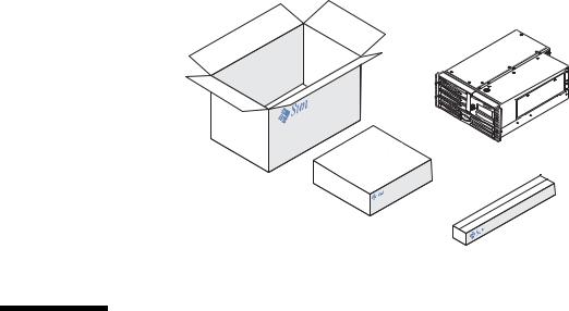
Unpacking instructions are printed on the outside of the shipping carton.
How to Install the Sun Fire V490 Server
Each step in this procedure refers you to a particular document or to a section of this guide for instructions. Complete each step in the order listed.
The best way to begin your installation of a Sun Fire V490 server is by completing the rackmounting and setup procedures in the Sun Fire V490 Server Setup and Rackmounting Guide. This guide is shipped with your server in the ship kit box.
Before You Begin
The Sun Fire V490 server is a general-purpose server, which you can use for many types of applications. Exactly how you set up your server depends on what you want it to do.
This procedure is intended to be as “generic” as possible, so as to cover the needs of most sites. Even so, you need to make certain decisions to complete the procedure:
■ On which network or networks do you intend the machine to operate?
2 Sun Fire V490 Server Administration Guide • August 2004
Loading...