


SB1049F
MODEL SB1049F HEAVY-13
13" X 30" GEARHEAD LATHE w/DRO
Manual Insert
PHONE: (360) 734-1540 • www.southbendlathe.com
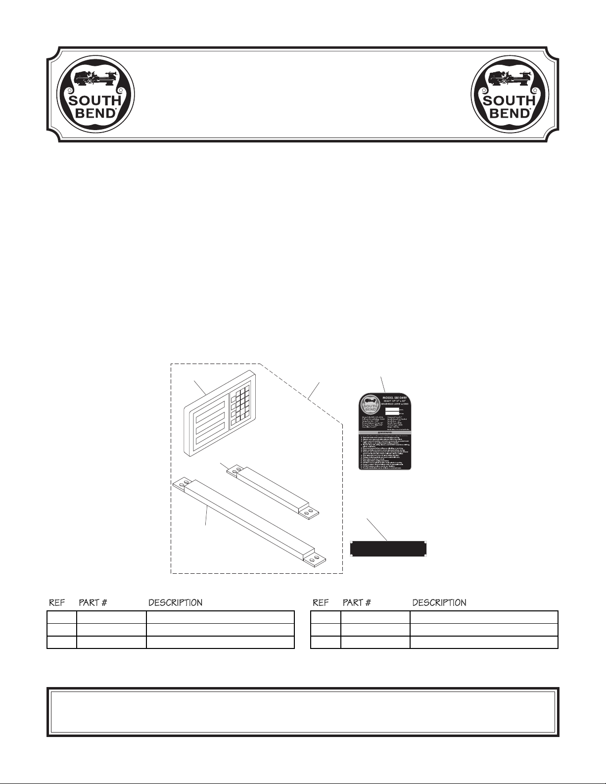
The Model SB1049F Lathe is the same machine as the Model SB1049 except for the following:
• Added a 2-Axis Fagor Digital Readout (DRO).
Except for the differences noted in this insert, all other content in the Model SB1049 Owner’s Manual
applies to this machine. Before operating your new lathe, you MUST read and understand this insert,
the entire Model SB1049 Owner’s Manual, and the Fagor DRO Owner’s Manual to reduce the risk of
injury when using this machine. Keep this insert for later reference.
If you have any further questions about this manual insert or the differences between the Model
SB1049F and the Model SB1049, contact our Technical Support at (360) 734-1540 or email
sales@southbendlathe.com.
New & Changed Parts
1570-1
1570-2
1570
1570-3
1615
1620
SB1049F
REF PART # DESCRIPTION REF PART # DESCRIPTION
1570 PSB1049F1570 DRO ASSEMBLY FAGOR 2-AXIS 1570-3 PSB1049F1570-3 DRO Y-AXIS SCALE FAGOR MKT-27
1570-1 PSB1049F1570-1 DRO DISPLAY FAGOR 20-iT 1615 PSB1049F1615 MACHINE ID LABEL
1570-2 PSB1049F1570-2 DRO X-AXIS SCALE FAGOR MKT-102 1620 PSB1049F1620 MODEL NUMBER BRASS PLATE
Copyright © December, 2013 by South Bend Lathe Co.
WARNING: No portion of this manual may be reproduced without written approval.
#TS16215 Printed in Taiwan
V1.12.13

Model SB1049F
Heavy 13 - 13" x 30" Gearhead Lathe with
Product Dimensions
Weight........................................................................................................................................................... 1881 lbs.
Width (side-to-side) x Depth (front-to-back) x Height.....................................................................
Footprint (Length x Width)...........................................................................................................
Shipping Dimensions
Type.......................................................................................................................................................... Wood Crate
Content.......................................................................................................................................................... Machine
Weight........................................................................................................................................................... 2472 lbs.
Length x Width x Height...................................................................................................................
MANUAL INSERT
Model SB1049F
Fagor DRO
Mfd. Since 12/13
90 x 38 x 69 in.
80-3/4 x 19-1/2 in.
43 x 78 x 73 in.
Electrical
Power Requirement.........................................................................................................
Full-Load Current Rating............................................................................................................................... 19.45A
Minimum Circuit Size.......................................................................................................................................... 30A
Connection Type..................................................................................................................................... Cord & Plug
Power Cord Included..............................................................................................................................................
Recommended Power Cord.............................................................................
Plug Included.......................................................................................................................................................... No
Recommended Plug Type.................................................................................................................................. L6-30
Switch Type....................................................................................... Control Panel w/Magnetic Switch Protection
"S"-Type, 3-Wire, 12 AWG, 300 VAC
220V, Single-Phase, 60 Hz
Motors
Main
Type.............................................................................................................
Horsepower...............................................................................................................................................
Phase............................................................................................................................................ Single-Phase
Amps........................................................................................................................................................... 19A
Speed................................................................................................................................................ 1725 RPM
Power Transfer ............................................................................................................................
Bearings................................................................................................
Coolant Pump
Type............................................................................................. TEFC Capacitor-Start Induction (Class F)
Horsepower............................................................................................................................................ 1/8 HP
Phase............................................................................................................................................ Single-Phase
Amps........................................................................................................................................................
Speed................................................................................................................................................
Power Transfer ............................................................................................................................ Direct Drive
Bearings................................................................................................ Shielded & Permanently Lubricated
TEFC Capacitor-Start Induction
Shielded & Permanently Lubricated
No
3 HP
V-Belt Drive
0.45A
3450 RPM
-2-

Mfd. Since 12/13 Model SB1049F
MANUAL INSERT
Main Specifications
Operation Info
Swing Over Bed.................................................................................................................................. 13.38 in.
Distance Between Centers...................................................................................................................... 30 in.
Max Weight Between Centers.............................................................................................................
Swing Over Cross Slide........................................................................................................................
Swing Over Saddle............................................................................................................................. 11.02 in.
Swing Over Gap....................................................................................................................................... 20 in.
Maximum Tool Bit Size.......................................................................................................................... 3/4 in.
Compound Travel......................................................................................................................................
Carriage Travel..................................................................................................................................
Cross Slide Travel...................................................................................................................................... 7 in.
Headstock Info
Spindle Bore.......................................................................................................................................... 1.57 in.
Spindle Size............................................................................................................................................. MT#5
Number of Spindle Speeds..............................................................................................................................
Spindle Speeds.........................................................................................................................
Spindle Type.............................................................................................................................. D1-5 Camlock
Spindle Bearings...................................................................................................................... Tapered Roller
Spindle Length.................................................................................................................................. 20-7/8 in.
Spindle Length with 3-Jaw Chuck.........................................................................................................
Spindle Length with 4-Jaw Chuck.........................................................................................................
Spindle Length with Faceplate......................................................................................................... 22-1/2 in.
80 – 2000 RPM
440 lbs.
8.26 in.
4 in.
26-1/2 in.
8
27 in.
25 in.
Tailstock Info
Tailstock Quill Travel.......................................................................................................................... 4-1/2 in.
Tailstock Taper........................................................................................................................................ MT#3
Tailstock Barrel Diameter..................................................................................................................
Threading Info
Number of Longitudinal Feeds.....................................................................................................................
Range of Longitudinal Feeds......................................................................................... 0.002 – 0.067 in./rev.
Number of Cross Feeds................................................................................................................................. 17
Range of Cross Feeds..................................................................................................... 0.001 – 0.034 in./rev.
Number of Inch Threads...............................................................................................................................
Range of Inch Threads.....................................................................................................................
Number of Metric Threads........................................................................................................................... 39
Range of Metric Threads........................................................................................................... 0.2 – 14.0 mm
Number of Modular Pitches.......................................................................................................................... 18
Range of Modular Pitches............................................................................................................
Number of Diametral Pitches.......................................................................................................................
Range of Diametral Pitches.............................................................................................................. 8 – 44 DP
Dimensions
Bed Width.................................................................................................................................................. 9 in.
Leadscrew Diameter............................................................................................................................ 1-1/8 in.
Leadscrew TPI.........................................................................................................................................
Leadscrew Length....................................................................................................................................
Steady Rest Capacity............................................................................................................. 5/16 – 4-5/16 in.
Follow Rest Capacity.................................................................................................................. 5/8 – 3-1/8 in.
Faceplate Size.......................................................................................................................................... 10 in.
Feed Rod Diameter.................................................................................................................................
Floor to Center Height......................................................................................................................
Height With Leveling Jacks.................................................................................................................... 59 in.
1.968 in.
17
45
2 – 72 TPI
0.3 – 3.5 MP
21
4 TPI
59 in.
3/4 in.
42-1/4 in.
-3-

Model SB1049F
Construction
Fluid Capacities
Other
Country Of Origin .......................................................................................................................................... Taiwan
Warranty ......................................................................................................................................................... 1 Year
Approximate Assembly & Setup Time .......................................................................................................... 1 Hour
Serial Number Location ................................................................................. ID Label on Rear Side of Left Stand
Sound Rating .................................................................................................................................................... 71 dB
ISO 9001 Factory ................................................................................................................................................... No
CSA Certified ......................................................................................................................................................... No
MANUAL INSERT
Base.................................................................................................................................................... Cast Iron
Headstock.......................................................................................................................................... Cast Iron
End Gears....................................................................................................................
Bed.................................................................
Body................................................................................................................................................... Cast Iron
Stand.................................................................................................................................................. Cast Iron
Paint................................................................................................................................................... Urethane
Headstock Capacity................................................................................................................................
Headstock Fluid Type...........................................................
Gearbox Capacity.................................................................................................................................... 1.4 qt.
Gearbox Fluid Type.................................................................. ISO 68 (eg. Grizzly T23962, Mobil Vactra 2)
Apron Capacity....................................................................................................................................... 1.2 qt.
Apron Fluid Type.....................................................................
Coolant Capacity...................................................................................................................................
Induction-Hardened, Precision-Ground Meehanite Cast Iron
ISO 32 (eg. Grizzly T23963, Mobil DTE Light)
ISO 68 (eg. Grizzly T23962, Mobil Vactra 2)
Mfd. Since 12/13
Flame Hardened Steel
6.4 qt.
11.1 qt.
Features
Allen Bradley Electrical Components
Signature South Bend 3 V-Way Bed
Safety Chuck Guard with Micro-Switch Shut-Off
Meehanite Castings with Induction-Hardened Ways
Halogen Work Light
4-Way Tool Post
Complete Coolant System
Micrometer Carriage Stop
Threading Dial Indicator
NSK or NTN Japanese Spindle Bearings
Full Length Splash Guard with Rounded Corner
Front Removable Sliding Chip Tray
Completely Enclosed Universal Gearbox for Cutting Inch, Metric, Modular and Diametral Pitches
Jog Button and Emergency Stop
Foot Brake
Headstock Gears Run in and Oil Bath
Fagor DRO
-4-

13" HEAVY 13® GEARHEAD LATHE
MODEL SB1049 13" X 30"
MODEL SB1050 13" X 40"
OWNER'S MANUAL
© January, 2012 by South Bend Lathe Co. For Machines Mfg. Since 5/11

Se
ce
W
Co.
.O. Bo
7
7
0
)
y)
sales@southbendlathe.com
:
.southbendlathe.co
cope of Manua
l
g op
happ
tact ou
cation
?
.
/
7
llingh
7
This manual helps the reader understand the machine, how to prepare it for operation, how to control
it durin
nderstanding of how to operate this type of machine, but that the reader is not familiar with the
ontrols and adjustments of this specific model. As with all machinery of this nature, learning the
uances of operation is a process that happens through training and experience. If you are not an
xperienced operator of this type of machinery, read through this entire manual, then learn more
from an experienced operator, schooling, or research before attempting operations. Following this
dvice will help you avoid serious personal injury and get the best results from your work.
eration, and how to keep it in good working condition. We assume the reader has a basic
Manual Feedback
We've made every effort to be accurate when documenting this machine. However, errors sometimes
en or the machine design changes after the documentation process—so
xactly match your machine. If a difference between the manual and machine leaves you in doubt,
n
We highly value customer feedback on our manuals. If you have a moment, please share your
xperience using this manual. What did you like about it? Is there anything you would change to
ake it better? Did it meet your expectations for clarity, professionalism, and ease-of-use
r
mer service for
larifi
e manual may not
South Bend Lathe, Inc
echnical Documentation Manager
Box 202
e
mail: manuals@southbendlathe.com
am, WA 9822
ates
For your convenience, any updates to this manual will be available to download free of charge
hrough our website at
www
ustomer
e stand behind our machines. If you have any service questions, parts requests or general questions
out your purchase, feel free to contact us.
h Bend Lathe
P
Bellingham, WA 9822
Phone: (360) 734-154
Fax: (360) 676-1075 (International
Fax: (360) 734-1639 (USA Onl
x 202
m
rvi

Table of Contents
INTRODUCTION .................................................... 3
About This Machine .............................................3
Foreword ............................................................. 3
Capabilities ......................................................... 3
Features .............................................................. 3
General Identification ..........................................4
Controls & Components.......................................5
Master Power Switch ........................................... 5
Headstock ...........................................................5
Control Panel ......................................................6
Carriage .............................................................. 6
Tailstock .............................................................7
End Gears ...........................................................7
Safety Foot Brake ................................................ 7
Product Specifications .........................................8
SAFETY ................................................................12
Understanding Risks of Machinery .................. 12
Basic Machine Safety ........................................12
Additional Metal Lathe Safety ..........................14
Additional Chuck Safety....................................15
PREPARATION .................................................... 16
Preparation Overview ........................................ 16
Things You'll Need .............................................16
Power Supply Requirements ............................. 17
Availability ........................................................ 17
Full-Load Current Rating ..................................17
Circuit Requirements ......................................... 17
Grounding Requirements ................................... 18
Extension Cords ................................................18
Unpacking ..........................................................19
Inventory ............................................................ 19
Cleaning & Protecting ....................................... 20
Location .............................................................. 21
Physical Environment ........................................ 21
Electrical Installation ........................................ 21
Lighting ............................................................21
Weight Load ...................................................... 21
Space Allocation ................................................21
Lifting & Moving ................................................22
Leveling & Mounting ......................................... 23
Leveling ............................................................23
Bolting to Concrete Floors ..................................24
Assembly ............................................................24
Lubricating Lathe ..............................................24
Adding Coolant ..................................................25
Power Connection .............................................. 25
Test Run ............................................................. 26
Spindle Break-In ................................................30
Recommended Adjustments ..............................30
OPERATION ........................................................31
Operation Overview ........................................... 31
Chuck & Faceplate Mounting ........................... 32
Installation & Removal Devices ........................32
Chuck Installation ............................................. 33
Registration Marks ............................................ 34
Chuck Removal .................................................. 34
Scroll Chuck Clamping ...................................... 35
4-Jaw Chuck ....................................................... 35
Mounting Workpiece .......................................... 35
Faceplate ............................................................36
Tailstock ............................................................. 37
Positioning Tailstock .........................................37
Using Quill ........................................................ 37
Installing Tooling ..............................................38
Removing Tooling .............................................. 39
Offsetting Tailstock ...........................................39
Aligning Tailstock to Spindle Centerline ............40
Centers ...............................................................41
Dead Centers .....................................................41
Live Centers ...................................................... 42
Mounting Dead Center in Spindle ...................... 42
Removing Center from Spindle ........................... 42
Mounting Center in Tailstock ............................. 42
Removing Center from Tailstock ........................43
Mounting Workpiece Between Centers ............... 43
Steady Rest ........................................................44
Follow Rest ......................................................... 45
Carriage & Slide Locks ...................................... 45
Compound Rest ..................................................46
Four-Way Tool Post ........................................... 46
Installing Tool ................................................... 46
Aligning Cutting Tool with Spindle Centerline ...47
Adjustable Feed Stop ......................................... 48
Micrometer Stop.................................................48
Manual Feed ......................................................49
Carriage Handwheel .......................................... 49
Cross Slide Handwheel ...................................... 49
Compound Rest Handwheel ............................... 49
Spindle Speed .....................................................49
Determining Spindle Speed ................................ 49

Setting Spindle Speed ........................................ 50
Configuration Examples ..................................... 50
Power Feed ......................................................... 51
Power Feed Controls .......................................... 52
Setting Power Feed Rate ....................................53
End Gears ........................................................... 54
Standard End Gear Configuration ...................... 54
Alternate Configuration ..................................... 55
Threading ........................................................... 56
Headstock Threading Controls ........................... 56
Apron Threading Controls..................................57
Thread Dial ....................................................... 57
Thread Dial Chart .............................................58
Chip Drawer ....................................................... 59
Coolant System .................................................. 60
ACCESSORIES ...................................................61
MAINTENANCE ...................................................64
Maintenance Schedule ....................................... 64
Cleaning & Protecting ....................................... 64
Maintenance Chart ............................................ 65
Lubrication ......................................................... 66
Headstock .........................................................66
Quick-Change Gearbox ...................................... 67
Apron ................................................................ 67
One-Shot Oiler ..................................................68
Longitudinal Leadscrew .....................................68
Ball Oilers & Oil Cup .........................................69
End Gears .........................................................70
Coolant System Service .....................................71
Hazards.............................................................71
Adding Fluid .....................................................72
Changing Coolant .............................................. 72
Machine Storage ................................................ 73
SERVICE .............................................................. 74
Backlash Adjustment ........................................74
Compound Rest .................................................74
Cross Slide ........................................................74
Leadscrew End Play Adjustment ......................75
Gib Adjustment .................................................. 75
Half Nut Adjustment ......................................... 77
V-Belts ................................................................ 77
Brake & Switch .................................................. 78
Leadscrew Shear Pin Replacement ..................80
Gap Insert Removal & Installation ..................82
Gap Removal ..................................................... 82
Gap Installation ................................................83
TROUBLESHOOTING .........................................84
ELECTRICAL ........................................................87
Electrical Safety Instructions ...........................87
Wiring Overview ................................................88
Component Location Index................................89
Electrical Cabinet Wiring ..................................90
Electrical Box .....................................................91
Spindle Motor .....................................................92
Coolant Pump Motor Wiring .............................92
Control Panel Wiring ......................................... 93
Spindle Switches ................................................ 93
Additional Component Wiring .......................... 94
Power Connection .............................................. 94
PARTS ..................................................................95
Headstock Cover ................................................ 95
Headstock Controls ............................................96
Headstock Internal Gears ................................. 98
Headstock Transfer Gears ............................... 100
Gearbox Gears .................................................. 101
Gearbox Controls ............................................. 103
Apron Front View ............................................105
Apron Rear View .............................................. 107
Compound Rest & Tool Post ............................109
Saddle Top View ..............................................110
Saddle Bottom View.........................................112
Micrometer Stop...............................................113
Dial Indicator ...................................................113
Bed & Shafts .................................................... 114
End Gears ......................................................... 116
Main Motor .......................................................117
Stands & Panels ............................................... 119
Tailstock ........................................................... 121
Steady Rest ......................................................123
Follow Rest ....................................................... 123
Electrical Cabinet & Control Panel ................ 124
Accessories .......................................................125
Front Machine Labels ......................................126
Rear & Side Machine Labels ........................... 127
WARRANTY ....................................................... 129

For Machines Mfg. Since 5/11 13" Heavy 13® Gearhead Lathe
INTRODUCTION
About This Machine
Foreword
"The screw cutting engine lathe is the oldest and
most important of machine tools and from it all
other machine tools have been developed. It was
the lathe that made possible the building of the
steamboat, the locomotive, the electric motor, the
automobile and all kinds of machinery used in
industry. Without the lathe our great industrial
progress of the last century would have been
impossible." —How To Run a Lathe, 15th
Edition, South Bend Lathe.
The lathe represented in this manual is a
modern day version of the screw cutting lathes
that trace their roots back to the 1700's, which
were themselves technological improvements of
the bow lathe that can be traced back thousands
of years to the ancient Egyptians.
Now, almost 300 years later, these modern
"screw cutting" lathes are not just a piece of
refined machinery, but a culmination of human
ingenuity and knowledge embodied into the
design and synergy of thousands of interworking
parts—some of which represent the life's work
and dreams of many inventors, mechanical
engineers, and world-class machinists—including
the likes of Leonardo da Vinci, Henry Maudsley,
and the founders of South Bend Lathe, John and
Miles O'Brien.
And now the torch is passed to you—to take
the oldest and most important type of machine
tool—and carry on the tradition. As the operator
of a South Bend Lathe, you now join the ranks
of some very famous and important customers,
such as Henry Ford, who used the machines he
purchased to help him change the world.
Features
These Heavy 13® Gearhead Lathes are packed
with standard features and equipment, such
as a complete coolant system, easy-to-clean
chip drawer, one-shot way lubrication system,
included steady and follow rests, chuck guard,
adjustable work lamp, foot brake, powered
cross feed, 3- and 4-jaw chucks, faceplate, and
premium Allen-Bradley contactors, thermal
relays, and fuse system.
Spindle speeds are controlled by convenient
headstock levers, which allow the operator to
quickly set the spindle speed within the available
range of 80–2000 RPM.
The beds of these lathes are constructed with
Meehanite castings that are hardened and
precision-ground in the traditional three V-way
prismatic design—long used on South Bend
Lathes for its accuracy, durability, and rigidity.
The headstocks feature quick-change gear levers
and the carriages include an adjustable clutch
that disables automatic carriage feed when it
contacts the included feed stop or in the event of
a crash.
To further ensure a high degree of accuracy,
these lathes are equipped with Japanese spindle
bearings. The spindles are D1-5 camlock with an
MT#5 taper and 1.57" bore. The tailstocks have
an MT#3 taper and 4.5" of quill travel.
Capabilities
This Heavy 13® Gearhead Lathe is built for daily
use in a busy industrial setting. Loaded with
many nice features and high-precision parts, this
lathe excels at making fine tools, dies, thread
gauges, jigs, and precision test gauges—however,
it is by no means delicate. Thick castings, heavy
weight, and quality construction throughout
provide the necessary brawn for demanding
production and manufacturing tasks.
South Bend Precision Toolroom Lathe
(Circa 1958)
-3-
13" Heavy 13® Gearhead Lathe
INTRODUCTION
General Identification
For Machines Mfg. Since 5/11
F
E
A
B
U
T
S
D
C
R
Q
G
P
O
H
I
J
K
L
M
N
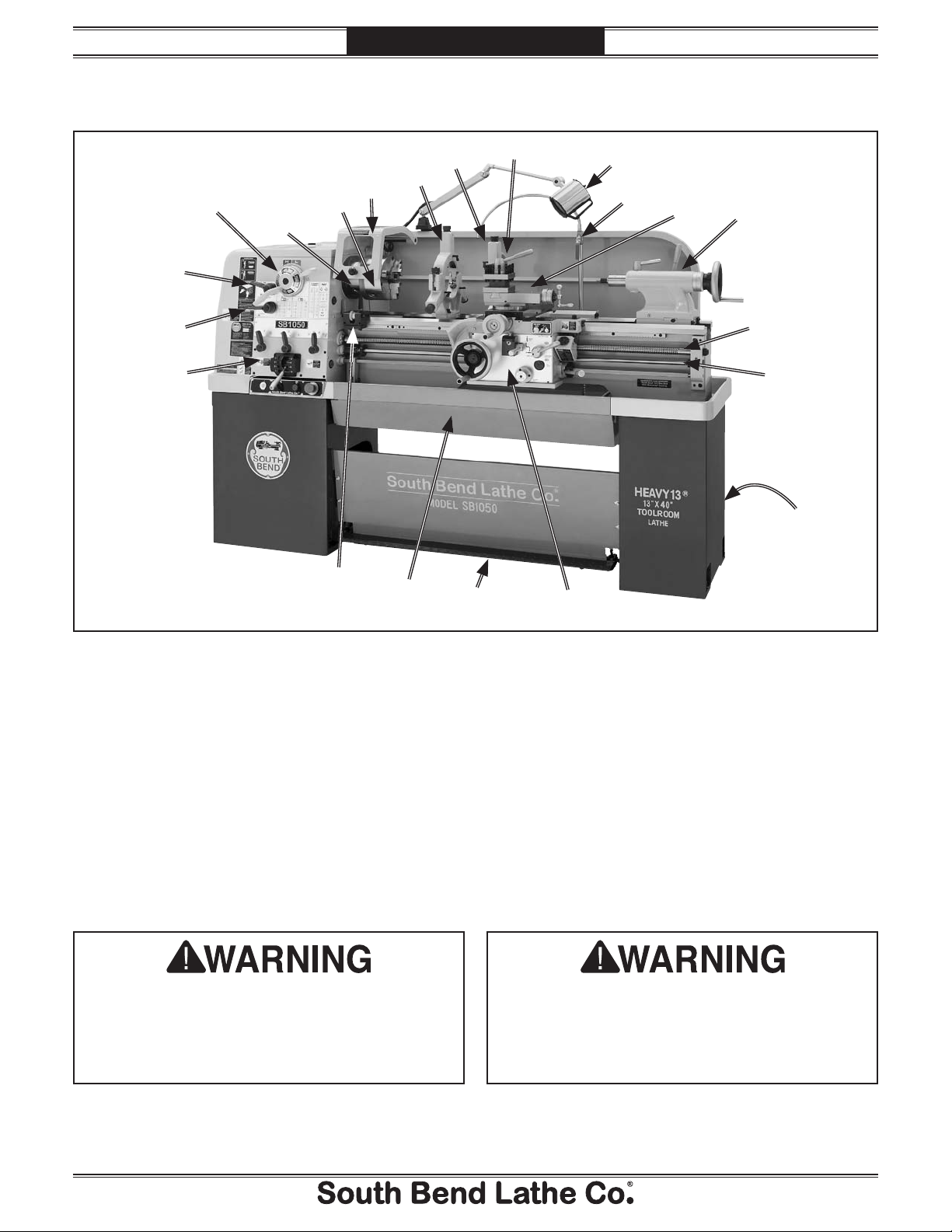
Figure 1. Identification.
A. Spindle Speed Levers (see Page 50 for
details)
B. D1-5 Camlock MT#5 Spindle
C. 3-Jaw Chuck 8"
D. Chuck Guard w/Safety Switch
E. Steady Rest
F. Follow Rest
G. 4-Way Tool Post
H. Halogen Work Lamp
I. Coolant Nozzle & Valve
J. Compound Rest
K. Tailstock (see Page 7 for details)
Serious personal injury could occur if
you connect the machine to power before
completing the setup process. DO NOT
connect power until instructed to do so later
in this manual.
L. Longitudinal Leadscrew
M. Feed Rod
N. Coolant Reservoir & Pump Access
O. Carriage (see Page 6 for details)
P. Safety Foot Brake
Q. Chip Drawer
R. Micrometer Stop
S. Quick-Change Gearbox Controls
(see Page 5 for details)
T. Headstock Feed Direction Lever
U. Gearbox Range Lever
Untrained users have an increased risk
of seriously injuring themselves with this
machine. Do not operate this machine until
you have understood this entire manual and
received proper training.
-4-
For Machines Mfg. Since 5/11 13" Heavy 13® Gearhead Lathe
Controls &
INTRODUCTION
A. Quick-Change Gearbox Levers: Control the
leadscrew and feed rod speed for threading
and feed operations.
Components
Refer to Figures 2–6 and the following
descriptions to become familiar with the basic
controls of this lathe.
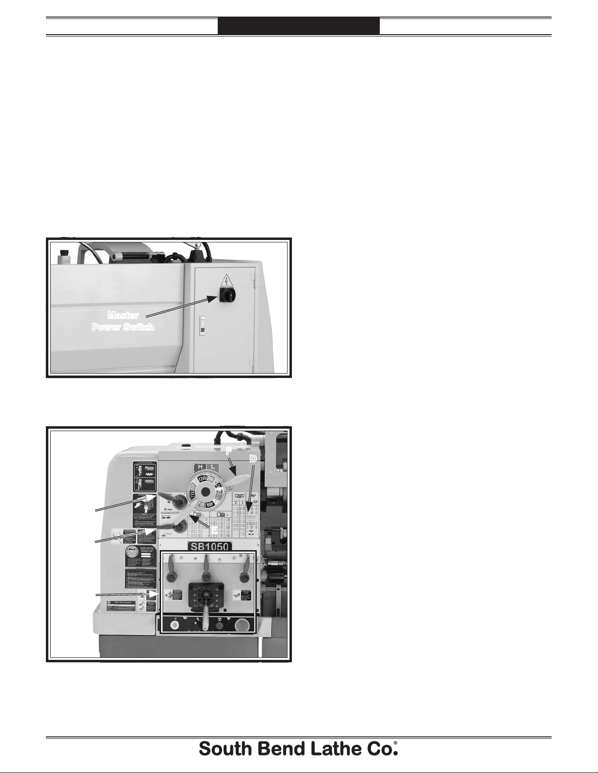
Master Power Switch
The rotary switch shown in Figure 2 toggles
incoming power ON and OFF to the lathe
controls. It also prevents the electrical cabinet
door from being opened when the switch is ON.
Master
Power Switch
B. Headstock Feed Direction Lever: Controls
the direction that the leadscrew and feed rod
rotate.
C. Gearbox Range Lever: Shifts the quick-
change gearbox into low range, neutral, or
high range.
D. Threading and Feed Charts: Display the
necessary configuration of the gearbox levers
and end gears for different threading or
feeding options.
E. Spindle Speed Lever: Selects one of the four
available spindle speeds within the selected
speed range.
F. Spindle Range Lever: Selects the spindle
speed high range (to the left) or the low
range (to the right).
Figure 2. Location of the master power switch.
Headstock
F
C
E
B
A
D
Figure 3. Headstock controls.
-5-
13" Heavy 13® Gearhead Lathe
INTRODUCTION
For Machines Mfg. Since 5/11
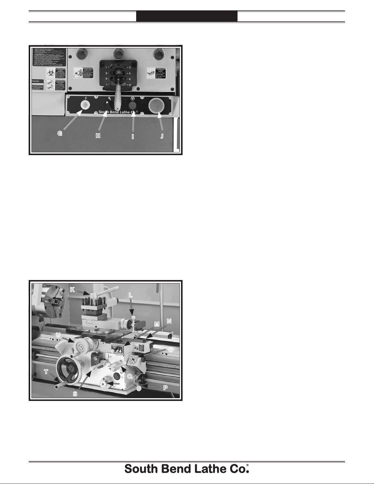
Control Panel
G
Figure 4. Control panel.
G. Power Light: Illuminates when lathe controls
are receiving power.
H. Coolant Pump Switch: Controls the coolant
pump motor.
I. Jog Button: Starts forward spindle rotation
as long as it is pressed.
J. STOP Button: Stops all machine functions.
Twist clockwise to reset.
H
I
J
Carriage
K
L
K. 4-Way Tool Post: Mounts up to four cutting
tools at once that can be individually indexed
to the workpiece.
L. Compound Rest Handwheel: Moves the tool
toward and away from the workpiece at the
preset angle of the compound rest.
M. One-Shot Oiler: Draws oil from the apron
reservoir to lubricate the carriage ways
through various oil ports.
N. Carriage Lock: Secures the carriage in place
when to ensure accuracy during operations
where it should not move.
O . Thread Dial and Chart: Dial indicates when
to engage the half nut during inch threading
operations. Chart indicates which thread
dial reading to engage the half nut for
specific inch thread pitches.
P. Spindle Lever: Starts and stops spindle
rotation in either direction.
Q . Half Nut Lever: Engages/disengages the half
nut for threading operations.
R. Apron Feed Direction Knob: Changes
direction of the carriage or the cross slide
feed without having to stop the lathe and
move the headstock feed direction lever.
S. Feed Selection Lever: Selects the carriage or
cross slide for power feed operations.
-6-
M
N
T. Carriage Handwheel: Moves the carriage
along the bed.
U
O
T
S
Figure 5. Carriage controls.
Q
R
P
U. Cross Slide Handwheel: Moves the cross
slide toward and away from the workpiece.
For Machines Mfg. Since 5/11 13" Heavy 13® Gearhead Lathe
INTRODUCTION
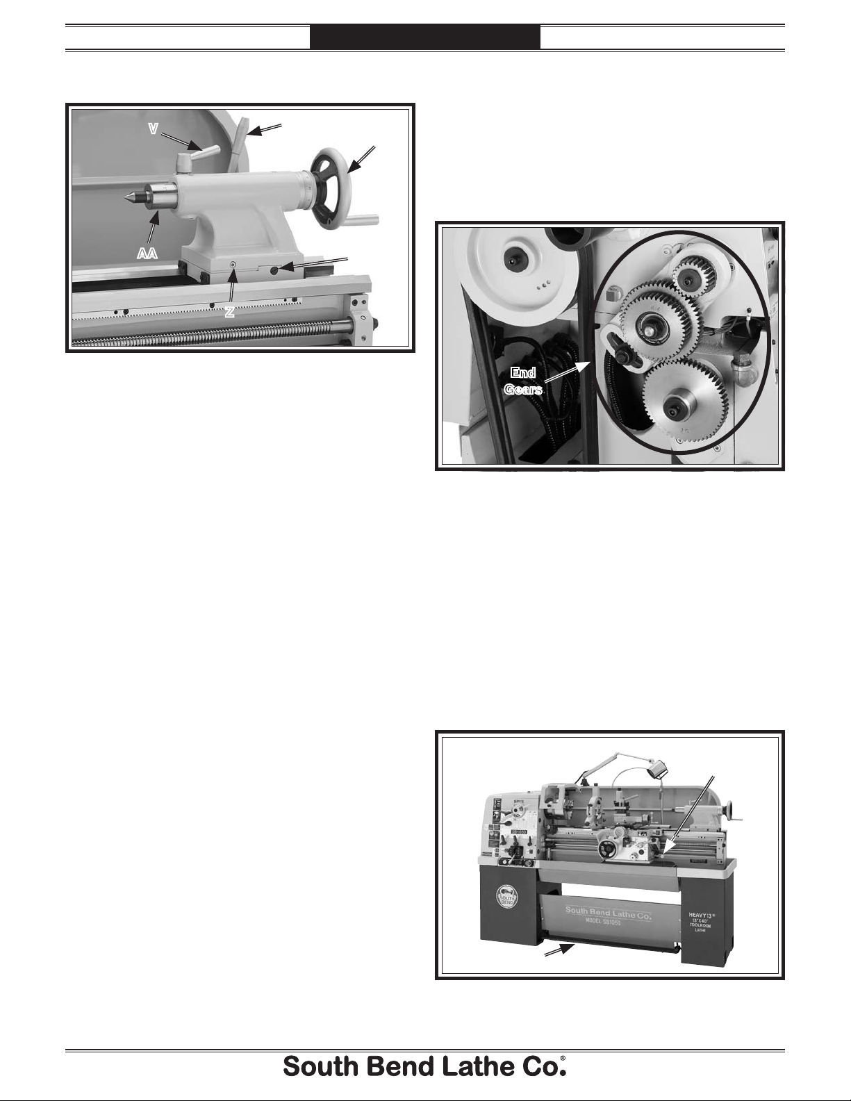
Tailstock
V
AA
Z
Figure 6. Tailstock controls.
V. Quill Lock Lever: Secures the quill in
position.
W. Tailstock Lock Lever: Secures the tailstock in
position along the bedway.
W
X
Y
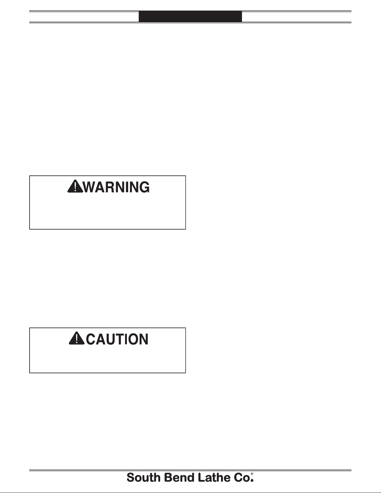
End Gears
Configuring the end gears shown in
Figure 7 will control the speed of the leadscrew
for threading or the feed rod for power feed
operations. The rotational speed of these
components depends not only on the end gear
configuration, but the spindle speed as well.
End
Gears
Figure 7. End gear components.
X. Quill Handwheel: Moves the quill toward or
away from the spindle.
Y. Gib Adjustment Screw: Adjusts the tapered
gib to control tailstock offset accuracy
(1 of 2).
Z. Tailstock Offset Screw: Adjusts the tailstock
offset left or right from the spindle centerline
(1 of 2).
AA. Quill: Moves toward and away from the
spindle and holds centers and tooling.
Safety Foot Brake
This lathe is equipped with a foot brake (see
Figure 8) to quickly stop the spindle instead of
allowing the spindle to coast to a stop on its own.
Pushing the foot brake while the spindle is ON
cuts power to the motor and stops the spindle.
After the foot brake is used, the spindle lever
must be returned to the OFF (middle) position
to reset the spindle switches before re-starting
spindle rotation.
Spindle
Lever
Foot Brake
Figure 8. Foot brake and spindle lever.
-7-

13" Heavy 13® Gearhead Lathe
Product Specifications
INTRODUCTION
For Machines Mfg. Since 5/11
Product Specifications
P.O. Box 2027, Bellingham, WA 98227 U.S.A.
0(/.%s© South Bend Lathe Co.
www.southbendlathe.com
MODEL SB1049 & SB1050
®
13" HEAVY 13
Model Number SB1049 SB1050
Product Dimensions
Weight 1870 lbs. 2205 lbs.
Width (side-to-side)/Depth
(front-to-back)/Height
Foot Print (Width/Depth) 69
Shipping Dimensions
Type Wood Slat Crate
Weight 2090 lbs. 2469 lbs.
Width (side-to-side)/Depth
(front-to-back)/Height
Electrical
Power Requirement 220V, Single-Phase, 60Hz
Full-Load Current Rating 19.5A
Minimum Circuit Size 30A
Switch Magnetic with Thermal Protection
Switch Voltage 220V
Plug Included No
Recommended Plug/Outlet Type NEMA L6-30
GEARHEAD LATHES
79" x 38" x 69" 90" x 38" x 69"
3
⁄4" x 19 1⁄2" 80 3⁄4" x 19 1⁄2"
79 x 38 x 69 79" x 45" x 69"
-8-

For Machines Mfg. Since 5/11 13" Heavy 13® Gearhead Lathe
INTRODUCTION
Model Number SB1049 SB1050
Main Motor
Type TEFC Induction
Horsepower 3 HP
Voltage 220V
Phase Single-Phase
Amps 19A
Speed 1720
Cycle 60 Hz
Power Transfer V-Belt & Gear
Bearings Shielded & Permanently Sealed
Coolant Motor
Type TEFC Induction
1
Horsepower
Voltage 220V
Phase Single-Phase
Amps 0.45A
Speed 3450 RPM
Cycle 60 Hz
Power Transfer Direct Drive
Bearings Shielded & Permanently Sealed Shielded & Permanently Sealed
Operation Information
Swing Over Bed 13.38"
Distance Between Centers 30" 40"
Swing Over Cross Slide 8.26"
Swing Over Saddle 11.02"
Swing Over Gap N/A 20"
Maximum Tool Bit Size 0.75"
Compound Travel 4"
Carriage Travel 36.5"
Cross Slide Travel 7"
⁄8 HP
-9-

13" Heavy 13® Gearhead Lathe
INTRODUCTION
For Machines Mfg. Since 5/11
Model Number SB1049 SB1050
Headstock Information
Spindle Bore 1.57"
Spindle Taper MT#5
Number of Spindle Speeds 8
Range of Spindle Speeds 80–2000 RPM
Spindle Type D1-5 Camlock
Spindle Bearings Tapered Roller
Tailstock Information
Tailstock Quill Travel 4.5"
Tailstock Taper MT#3
Tailstock Barrel Diameter 1.968"
Threading Information
Number of Longitudinal Feeds 17
Range of Longitudinal Feeds 0.002"–0.067"
Number of Cross Feeds 17
Range of Cross Feeds 0.001"–0.034"
Number of Inch Threads 45
Range of Inch Threads 2–72 TPI
Number of Metric Threads 39
Range of Metric Threads 0.2–14 mm
Number of Modular Pitches 18
Range of Modular Pitches 0.3–3.5 MP
Number of Diametral Pitches 21
Range of Diametral Pitches 8–44 DP
Dimensions
Bed Width 9"
1
Leadscrew Diameter 1
Leadscrew TPI 4 TPI
Leadscrew Length 47" 59"
Steady Rest Capacity
Follow Rest Capacity
Faceplate Size 10"
Feed Rod Diameter
Floor to Center Height 42.2"
Height With Leveling Jacks 59.06"
⁄8"
5
⁄16"–4 5⁄16"
5
⁄8"–3 1⁄8"
3
⁄4"
-10-

For Machines Mfg. Since 5/11 13" Heavy 13® Gearhead Lathe
INTRODUCTION
Model Number SB1049 SB1050
Construction
Headstock Cast Iron
Headstock Gears Flame-Hardened Steel
Bed Meehanite Castings with Precision Hardened-and-Ground Ways
Stand Cast Iron
Paint Urethane
Other
Country of Origin Taiwan (Some Components Made in USA & Japan)
Warranty 1 Year
Serial Number Location ID Label on Front of Headstock
1
Assembly Time Approximately 1
Sound Rating at Idle 71 dB
⁄2 Hours
-11-

13" Heavy 13® Gearhead Lathe
SAFETY
For Machines Mfg. Since 5/11
Understanding Risks of Machinery
Operating all machinery and machining equipment can be dangerous or relatively safe depending
on how it is installed and maintained, and the operator's experience, common sense, risk awareness,
working conditions, and use of personal protective equipment (safety glasses, respirators, etc.).
The owner of this machinery or equipment is ultimately responsible for its safe use. This
responsibility includes proper installation in a safe environment, personnel training and usage
authorization, regular inspection and maintenance, manual availability and comprehension,
application of safety devices, integrity of cutting tools or accessories, and the usage of approved
personal protective equipment by all operators and bystanders.
The manufacturer of this machinery or equipment will not be held liable for injury or property
damage from negligence, improper training, machine modifications, or misuse. Failure to read,
understand, and follow the manual and safety labels may result in serious personal injury, including
amputation, broken bones, electrocution, or death.
The signals used in this manual to identify hazard levels are as follows:
Death or catastrophic
harm WILL occur.
Death or catastrophic
harm COULD occur.
Basic Machine Safety
Owner’s Manual: All machinery and machining
equipment presents serious injury hazards
to untrained users. To reduce the risk of
injury, anyone who uses THIS item MUST
read and understand this entire manual
before starting.
Personal Protective Equipment:
servicing this item may expose the user
to flying debris, dust, smoke, dangerous
chemicals, or loud noises. These hazards
can result in eye injury, blindness, longterm respiratory damage, poisoning,
cancer, reproductive harm or hearing loss.
Reduce your risks from these hazards
by wearing approved eye protection,
respirator, gloves, or hearing protection.
Operating or
Moderate injury or fire
MAY occur.
Machine or property
damage may occur.
Trained/Supervised Operators Only: Untrained
users can seriously injure themselves
or bystanders. Only allow trained and
properly supervised personnel to operate
this item. Make sure safe operation
instructions are clearly understood. If
electrically powered, use padlocks and
master switches, and remove start switch
keys to prevent unauthorized use or
accidental starting.
Guards/Covers:
moving parts during operation may cause
severe entanglement, impact, cutting,
or crushing injuries. Reduce this risk by
keeping any included guards/covers/doors
installed, fully functional, and positioned
for maximum protection.
Accidental contact with
-12-

For Machines Mfg. Since 5/11 13" Heavy 13® Gearhead Lathe
SAFETY
Entanglement: Loose clothing, gloves, neckties,
jewelry or long hair may get caught in
moving parts, causing entanglement,
amputation, crushing, or strangulation.
Reduce this risk by removing/securing
these items so they cannot contact moving
parts.
Mental Alertness: Operating this item with
reduced mental alertness increases the
risk of accidental injury. Do not let a
temporary influence or distraction lead to a
permanent disability! Never operate when
under the influence of drugs/alcohol, when
tired, or otherwise distracted.
Safe Environment:
powered equipment in a wet environment
may result in electrocution; operating near
highly flammable materials may result in a
fire or explosion. Only operate this item in
a dry location that is free from flammable
materials.
Electrical Connection: With electically powered
equipment, improper connections to the
power source may result in electrocution
or fire. Always adhere to all electrical
requirements and applicable codes when
connecting to the power source. Have all
work inspected by a qualified electrician to
minimize risk.
Disconnect Power: Adjusting or servicing
electrically powered equipment while it
is connected to the power source greatly
increases the risk of injury from accidental
startup. Always disconnect power
BEFORE any service or adjustments,
including changing blades or other tooling.
Operating electrically
Chuck Keys or Adjusting Tools:
adjust spindles, chucks, or any moving/
rotating parts will become dangerous
projectiles if left in place when the machine
is started. Reduce this risk by developing
the habit of always removing these tools
immediately after using them.
Work Area:
the risks of accidental injury. Only operate
this item in a clean, non-glaring, and welllighted work area.
Properly Functioning Equipment:
maintained, damaged, or malfunctioning
equipment has higher risks of causing
serious personal injury compared to
those that are properly maintained.
To reduce this risk, always maintain
this item to the highest standards and
promptly repair/service a damaged or
malfunctioning component. Always follow
the maintenance instructions included in
this documentation.
Unattended Operation:
equipment that is left unattended while
running cannot be controlled and is
dangerous to bystanders. Always turn the
power OFF before walking away.
Health Hazards: Certain cutting fluids and
lubricants, or dust/smoke created when
cutting, may contain chemicals known to
the State of California to cause cancer,
respiratory problems, birth defects,
or other reproductive harm. Minimize
exposure to these chemicals by wearing
approved personal protective equipment
and operating in a well ventilated area.
Clutter and dark shadows increase
Electrically powered
Tools used to
Poorly
Secure Workpiece/Tooling:
cutting tools, or rotating spindles can
become dangerous projectiles if not
secured or if they hit another object during
operation. Reduce the risk of this hazard
by verifying that all fastening devices are
properly secured and items attached to
spindles have enough clearance to safely
rotate.
Loose workpieces,
Difficult Operations:
operations with which you are unfamiliar
increases the risk of injury. If you
experience difficulties performing the
intended operation, STOP! Seek an
alternative method to accomplish the
same task, ask a qualified expert how the
operation should be performed, or contact
our Technical Support for assistance.
Attempting difficult
-13 -

13" Heavy 13® Gearhead Lathe
SAFETY
Additional Metal Lathe Safety
For Machines Mfg. Since 5/11
Speed Rates. Operating the lathe at the wrong
speed can cause nearby parts to break or the
workpiece to come loose, which will result in
dangerous projectiles that could cause severe
impact injuries. Large or non-concentric
workpieces must be turned at slow speeds.
Always use the appropriate feed and speed
rates.
Chuck Key Safety. A chuck key left in the chuck
can become a deadly projectile when the
spindle is started. Always remove the chuck
key after using it. Develop a habit of not
taking your hand off of a chuck key unless it
is away from the machine.
Safe Clearances. Workpieces that crash into
other components on the lathe may throw
dangerous projectiles in all directions,
leading to impact injury and damaged
equipment. Before starting the spindle,
make sure the workpiece has adequate
clearance by hand-rotating it through its
entire range of motion. Also, check the tool
and tool post clearance, chuck clearance, and
saddle clearance.
Clearing Chips. Metal chips can easily cut bare
skin—even through a piece of cloth. Avoid
clearing chips by hand or with a rag.Use a
brush or vacuum to clear metal chips.
Stopping Spindle by Hand. Stopping the spindle
by putting your hand on the workpiece
or chuck creates an extreme risk of
entanglement, impact, crushing, friction, or
cutting hazards. Never attempt to slow or
stop the lathe spindle with your hand. Allow
the spindle to come to a stop on its own or
use the brake.
Crashes. Aggressively driving the cutting tool
or other lathe components into the chuck
may cause an explosion of metal fragments,
which can result in severe impact injuries
and major damage to the lathe. Reduce
this risk by releasing automatic feeds after
use, not leaving lathe unattended during
operation, and checking clearances before
starting the lathe. Make sure no part of the
tool, tool holder, compound rest, cross slide,
or carriage will contact the chuck during
operation.
Long Stock Safety. Long stock can whip violently
if not properly supported, causing serious
impact injury and damage to the lathe.
Reduce this risk by supporting any stock
that extends from the chuck/headstock more
than three times its own diameter. Always
turn long stock at slow speeds.
Securing Workpiece. An improperly secured
workpiece can fly off the lathe spindle with
deadly force, which can result in a severe
impact injury. Make sure the workpiece is
properly secured in the chuck or faceplate
before starting the lathe.
Chucks. Chucks are very heavy and difficult to
grasp, which can lead to crushed fingers or
hands if mishandled. Get assistance when
handling chucks to reduce this risk. Protect
your hands and the precision-ground ways
by using a chuck cradle or piece of plywood
over the ways of the lathe when servicing
chucks. Use lifting devices when necessary.
Coolant Safety. Coolant is a very poisonous
biohazard that can cause personal injury
from skin contact alone, especially when it
gets old or has been well-used. Incorrectly
positioned coolant nozzles can splash on
the operator or the floor, resulting in skin
exposure or a slipping hazard. To decrease
your risk, change coolant regularly and
position the nozzle where it will not splash
or end up on the floor.
Tool Selection. Cutting with an incorrect or
dull tool increases the risk of accidental
injury due to the extra force required for
the operation, which increases the risk of
breaking or dislodging components that
can cause small shards of metal to become
dangerous projectiles. Always select the
right cutter for the job and make sure it is
sharp. Using a correct, sharp tool decreases
strain and provides a better finish.
-14-

For Machines Mfg. Since 5/11 13" Heavy 13® Gearhead Lathe
SAFETY
Additional Chuck Safety
Entanglement. Entanglement with a rotating
chuck can lead to death, amputation, broken
bones, or other serious injury. Never attempt
to slow or stop the lathe chuck by hand,
and always roll up long sleeves, tie back
long hair, and remove any jewelry or loose
apparel BEFORE operating.
Chuck Speed Rating. Excessive spindle speeds
greatly increase the risk of the workpiece or
chuck being thrown from the machine with
deadly force. Never use spindle speeds faster
than the chuck RPM rating or the safe limits
of your workpiece.
Using Correct Equipment. Many workpieces can
only be safely turned in a lathe if additional
support equipment, such as a tailstock or
steady rest, is used. If the operation is too
hazardous to be completed with the lathe or
existing equipment, the operator must have
enough experience to know when to use a
different machine or find a safer way. If you
do not have this experience, seek additional
training (outside of this manual) from
experienced lathe operators, books, or formal
classes
Trained Operators Only. Using a chuck
incorrectly can result in workpieces coming
loose at high speeds and striking the
operator or bystanders with deadly force.
To reduce the risk of this hazard, read
and understand this document and seek
additional training from an experienced
chuck user before using a chuck.
Chuck Capacity. Avoid exceeding the capacity
of the chuck by clamping an oversized
workpiece. If the workpiece is too large to
safely clamp with the chuck, use a faceplate
or a larger chuck if possible. Otherwise, the
workpiece could be thrown from the lathe
during operation, resulting in serious impact
injury or death.
Clamping Force. Inadequate clamping force
can lead to the workpiece being thrown
from the chuck and striking the operator
or bystanders. Maximum clamping force
is achieved when the chuck is properly
maintained and lubricated, all jaws are
fully engaged with the workpiece, and the
maximum chuck clamping diameter is not
exceeded.
Proper Maintenance.
maintained and lubricated to achieve
maximum clamping force and withstand
the rigors of centrifugal force. To reduce
the risk of a thrown workpiece, follow all
maintenance intervals and instructions in
this document.
Disconnect Power. Serious entanglement or
impact injuries could occur if the lathe is
started while you are adjusting, servicing, or
installing the chuck. Always disconnect the
lathe from power before performing these
procedures.
All chucks must be properly
-15 -

13" Heavy 13® Gearhead Lathe
PREPARATION
For Machines Mfg. Since 5/11
Preparation Overview Things You'll Need
The purpose of the preparation section is to help
you prepare your machine for operation. The list
below outlines this basic process. Specific steps
for each of these points will be covered in detail
later in this section.
The typical preparation process is as follows:
1. Unpack the lathe and inventory the contents
of the box/crate.
2. Clean the lathe and its components.
3. Identify an acceptable location for the lathe
and move it to that location.
4. Level the lathe and either bolt it to the floor
or place it on mounts.
5. Assemble the loose components and make
any necessary adjustments or inspections to
ensure the lathe is ready for operation.
6. Check/lubricate the lathe.
To complete the preparation process, you will
need the following items:
For Lifting and Moving
s !FORKLIFTOROTHERPOWERLIFTINGDEVICE
rated for at least 25% more than the
shipping weight of the lathe (see Product
Specifications beginning on Page 1)
s ,IFTINGstraps, each rated for at least 25%
more than the shipping weight of the lathe
s 'UIDERODSFORSTEADINGTHELOADWHENLIFTING
s Two other people for assistance when moving
machine
s Hardwood blocks (see Page 22)
For Power Connection
s !POWERSOURCETHATMEETSTHEMINIMUM
circuit requirements for this machine (review
Power Supply Requirements on the next
page for details)
s !NELECTRICIANORQUALIFIEDSERVICEPERSONNEL
to ensure a safe and code-compliant
connection to the power source
7. Connect the lathe to the power source.
8. Test run the lathe to make sure it functions
properly.
9. Perform the spindle break-in procedure to
prepare the lathe for operation.
For Cleaning & Assembly
s Cotton rags
s Mineral spirits
s Quality metal protectant oil
s 3AFETYglasses
s Wrench or socket 21mm
s Wrench or socket 19mm
s &LOORmounting hardware as needed
s 0RECISIONLEVEL
s Standard screwdriver #2
-16 -
For Machines Mfg. Since 5/11 13" Heavy 13® Gearhead Lathe
A
Power Supply
Requirements
PREPARATION
The full-load current is not the maximum
amount of amps that the machine will draw. If
the machine is overloaded, it will draw additional
amps beyond the full-load rating.
Availability
Before installing the machine, consider the
availability and proximity of the required power
supply circuit. If an existing circuit does not meet
the requirements for this machine, a new circuit
must be installed.
To minimize the risk of electrocution, fire,
or equipment damage, installation work and
electrical wiring must be done by an electrician
or qualified service personnel in accordance with
all applicable codes.
Serious injury could occur if you connect
the machine to power before completing the
setup process. DO NOT connect to power until
instructed later in this manual.
Full-Load Current Rating
The full-load current rating is the amperage
a machine draws at 100% of the rated output
power. On machines with multiple motors, this is
the amperage drawn by the largest motor or sum
of all motors and electrical devices that might
operate at one time during normal operations.
If the machine is overloaded for a sufficient
length of time, damage, overheating, or fire may
result—especially if connected to an undersized
circuit. To reduce the risk of these hazards,
avoid overloading the machine during operation
and make sure it is connected to a power supply
circuit that meets the requirements in the
following section.
Circuit Requirements
This machine is prewired to operate on a 220V
power supply circuit that has a verified ground
and meets the following requirements:
Nominal Voltage ...............................220V/240V
Cycle .............................................................60 Hz
Phase ..............................................Single-Phase
Circuit Rating....................................... 30 Amps
Cord ......... "S" Type, 3-Wire, 12 AWG, 300 VAC
Plug/Receptacle ............................NEMA L6-30
power supply circuit includes all electrical
equipment between the main breaker box or fuse
panel in your building and the incoming power
connections inside the machine. This circuit
must be safely sized to handle the full-load
current that may be drawn from the machine for
an extended period of time. (If this machine is
SB1049 Full-Load Rating ................ 19.5 Amps
SB1050 Full-Load Rating ................ 19.5 Amps
For your own safety and protection of property,
consult an electrician if you are unsure about
wiring practices or applicable electrical codes.
Note: The circuit requirements in this manual
are for a dedicated circuit—where only one
machine will be running at a time. If this
machine will be connected to a shared circuit
where multiple machines will be running at
the same time, consult a qualified electrician to
ensure the circuit is properly sized.
-17-
13" Heavy 13® Gearhead Lathe
PREPARATION
This machine must be grounded! In the event
of certain types of malfunctions or breakdowns,
grounding provides a path of least resistance
for electric current in order to reduce the risk of
electric shock.
Improper connection of the equipment-grounding
wire can result in a risk of electric shock. The
wire with green insulation (with or without
yellow stripes) is the equipment-grounding
wire. If repair or replacement of the power cord
is necessary, do not connect the equipmentgrounding wire to a live (current carrying)
terminal.
Check with an electrician or qualified service
personnel if you do not understand these
grounding requirements, or if you are in doubt
about whether the machine is properly grounded.
If you ever notice that a cord is damaged or
worn, disconnect it from power, and immediately
replace it with a new one.
For Machines Mfg. Since 5/11
Extension CordsGrounding Requirements
We do not recommend using an extension cord
with this machine. If you must use an extension
cord, only use it if absolutely necessary and only
on a temporary basis.
Extension cords cause voltage drop, which may
damage electrical components and shorten motor
life. Voltage drop increases as the extension cord
size gets longer and the gauge size get smaller
(higher gauge numbers indicate smaller sizes).
Any extension cord used with this machine
must contain a ground wire, match the required
plug and receptacle, and meet the following
requirements:
Minimum Gauge Size ...............................12 AWG
Maximum Length (Shorter is Better) ........... 50 ft.
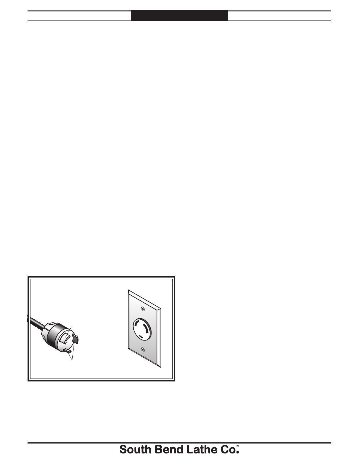
The power cord and plug specified under Circuit
Requirements section on the previous page has
an equipment-grounding wire and a grounding
prong. The plug must only be inserted into a
matching receptacle (outlet) that is properly
installed and grounded in accordance with all
local codes and ordinances (see Figure 9).
GROUNDED
L6-30 LOCKING
RECEPTACLE
Grounding Prong
is Hooked
L6-30
LOCKING
PLUG
Current Carrying Prongs
Figure 9. Typical NEMA L6-30 plug and receptacle.
-18 -
For Machines Mfg. Since 5/11 13" Heavy 13® Gearhead Lathe
PREPARATION
Unpacking
This item was carefully packaged to prevent
damage during transport. If you discover any
damage, please immediately call Customer
Service at (360) 734-1540 for advice. You may
need to file a freight claim, so save the containers
and all packing materials for possible inspection
by the carrier or its agent.
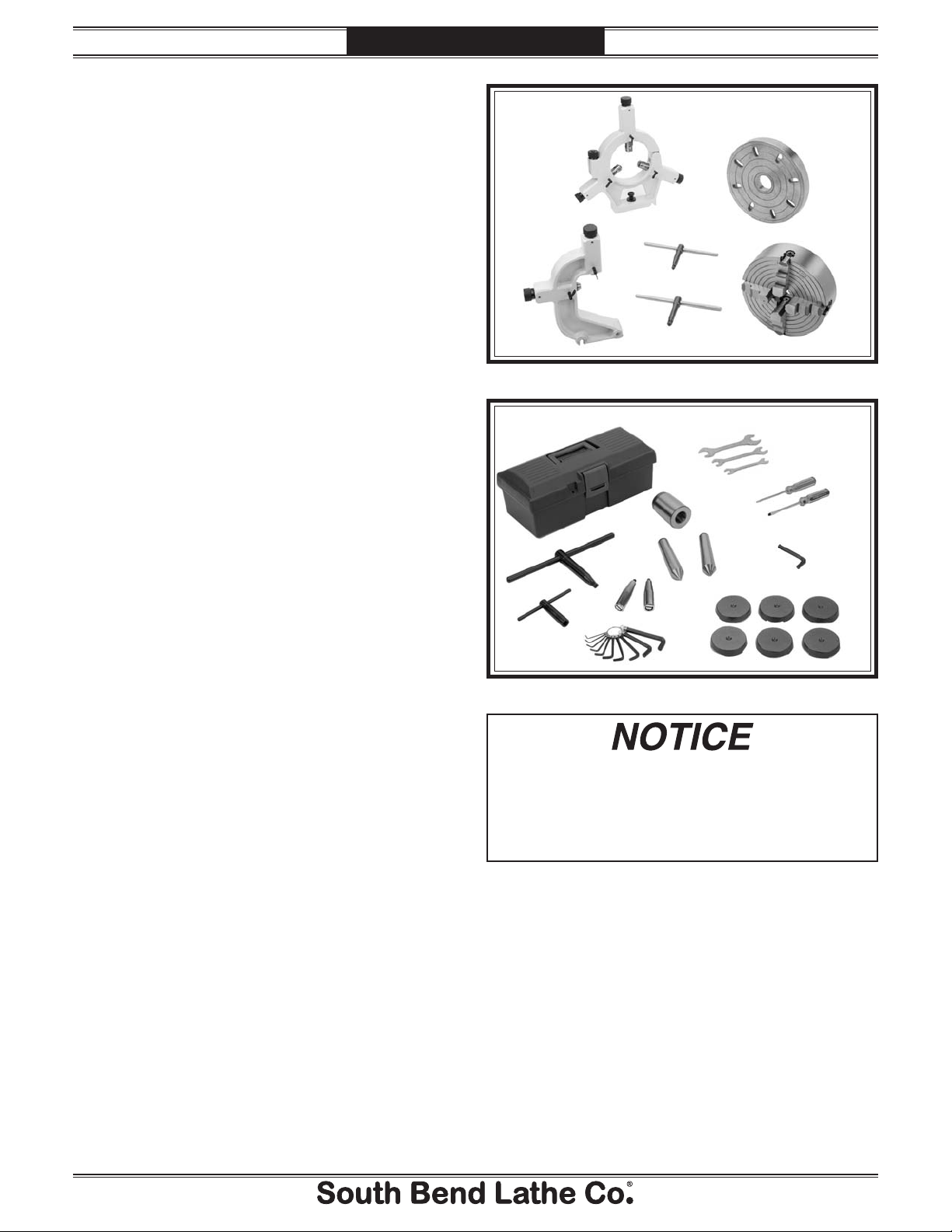
Inventory
Main Inventory 1: (Figure 10) Qty
A. Steady Rest Assembly (Installed) .................1
B. 10" Faceplate w/D1-5 Camlock Stud Set ......1
C. 8" 4-Jaw Chuck w/Combo Jaws (SB1226) .... 1
D. 3-Jaw Chuck Key ...........................................1
E. 4-Jaw Chuck Key ........................................... 1
F. Follow Rest Assembly (Installed) ..................1
Tool Box Inventory: (Figure 11) Qty
G. Tool Box .......................................................... 1
H. Open End Wrench 22/24mm .........................1
I. Open End Wrench 14/17mm .........................1
J. Open End Wrench 10/12mm .........................1
K. Phillips Screwdriver #2 .................................1
L. Standard Screwdriver #2 ...............................1
M. Hex Wrench 8mm .......................................... 1
N. Tapered Spindle Sleeve MT#5-#3 .................1
O. Dead Center MT#3 ......................................... 1
P. Carbide-Tipped Dead Center MT#3 ..............1
Q. Camlock Key D1-5 ......................................... 1
R. Tool Post T-Wrench (Clamped on Tool Post) 1
S. Hex Wrench Set 1.5-10mm ............................ 1
T. Carriage Handwheel Handle ......................... 1
U. Cross Slide Handwheel Handle .....................1
V. Cast Iron Leveling Pads ................................ 6
A
D
F
E
Figure 10. Main inventory.
G
Q
R
If you cannot find an item on this list, check
the mounting location on the machine or the
packaging materials. Sometimes parts are
pre-installed for shipping, or they become
hidden by packaging materials.
T
S
Figure 11. Toolbox inventory.
H
N
O
U
B
C
I
J
P
K
L
M
V
Pre-Installed (Not Shown) Qty
s 7" 3-Jaw Chuck (SB1308) ..............................1
1
s 8
Note: Some inventory components may be
shipped inside of the lathe electrical box. These
items MUST be removed before connecting the
lathe to the power source.
⁄4" Back Plate D1-5 (SB1399) ......................1
-19 -

13" Heavy 13® Gearhead Lathe
A
PREPARATION
Cleaning & Protecting
For Machines Mfg. Since 5/11
The unpainted surfaces are coated at the factory
with a heavy-duty rust preventative that
prevents corrosion during shipment and storage.
The benefit of this rust preventative is that it
works very well. The downside is that it can be
time-consuming to thoroughly remove.
Be patient and do a careful job when cleaning
and removing the rust preventative. The time
you spend doing this will reward you with
smooth-sliding parts and a better appreciation
for the proper care of the unpainted surfaces.
lthough there are many ways to successfully
remove the rust preventative, the following
process works well in most situations.
Before cleaning, gather the following:
s $ISPOSABLErags
s #LEANERDEGREASER (certain citrus-based
degreasers work extremely well and they
have non-toxic fumes)
s 3AFETYGLASSESDISPOSABLEGLOVES
Note: Automotive degreasers, mineral spirits, or
7$sCANBEUSEDTOREMOVERUSTPREVENTATIVE
Before using these products, though, test them
on an inconspicuous area of a painted surface to
make sure they will not damage it.
Avoid chlorine-based solvents, such as
acetone or brake parts cleaner that may
damage painted surfaces. Always follow the
manufacturer’s instructions when using any
type of cleaning product.
Basic steps for removing rust preventative:
1. Put on safety glasses and disposable gloves.
2. #OATALLSURFACESTHATHAVERUSTPREVENTATIVE
with a liberal amount of your cleaner or
degreaser and let them soak for a few
minutes.
3. Wipe off the surfaces. If your cleaner or
degreaser is effective, the rust preventative
will wipe off easily.
Note: To clean off thick coats of rust preventative
on flat surfaces, such as beds or tables, use
A0,!34)#PAINTSCRAPERTOSCRAPEOFFTHE
majority of the coating before wiping it off
WITHYOURRAG$ONOTUSEAMETALSCRAPEROR
it may scratch the surface.)
4. Repeat Steps 2–3 as necessary until clean,
then coat all unpainted surfaces with a
quality metal protectant or light oil to
prevent rust.
-20-
GAS
Gasoline and petroleum
products have low flash
points and can explode
or cause fire if used for
cleaning. Avoid using these
products to remove rust
preventative.
Many cleaning solvents are
toxic if inhaled. Minimize
your risk by only using
these products in a well
ventilated area.
Remove the end gear cover and end gears,
and use a stiff brush with mineral spirits
to clean the rust preventative from the
gears and shafts. DO NOT get any cleaner
or rust preventative on the V-belts, as it
could damage them or make them slip
during operations. If the belts do become
contaminated, replace them.
For Machines Mfg. Since 5/11 13" Heavy 13® Gearhead Lathe
PREPARATION
LocationLocation
Physical Environment
The physical environment where your machine
is operated is important for safe operation and
longevity of parts. For best results, operate this
machine in a dry environment that is free from
excessive moisture, hazardous or flammable
chemicals, airborne abrasives, or extreme
conditions. Extreme conditions for this type
of machinery are generally those where the
ambient temperature is outside the range of 41°–
104°F; the relative humidity is outside the range
of 20–95% (non-condensing); or the environment
is subject to vibration, shocks, or bumps.
Electrical Installation
Place this machine near an existing power source
that meets the minimum circuit requirements.
Make sure all power cords are protected from
traffic, material handling, moisture, chemicals,
or other hazards. Leave access to disconnect the
power source or engage a lockout/tagout device.
Weight Load
Refer to the Machine Specifications for the
weight of your machine. Make sure that the
surface upon which the machine is placed will
bear the weight of the machine, additional
equipment that may be installed on the machine,
and the heaviest workpiece that will be used.
Additionally, consider the weight of the operator
and any dynamic loading that may occur when
operating the machine.
Space Allocation
Consider the largest size of workpiece that will
be processed through this machine and provide
enough space around the machine for adequate
operator material handling or the installation
of auxiliary equipment. With permanent
installations, leave enough space around
the machine to open or remove doors/covers
as required by the maintenance and service
described in this manual.
Lighting
Lighting around the machine must be adequate
enough that operations can be performed
safely. Shadows, glare, or strobe effects that
may distract or impede the operator must be
eliminated.
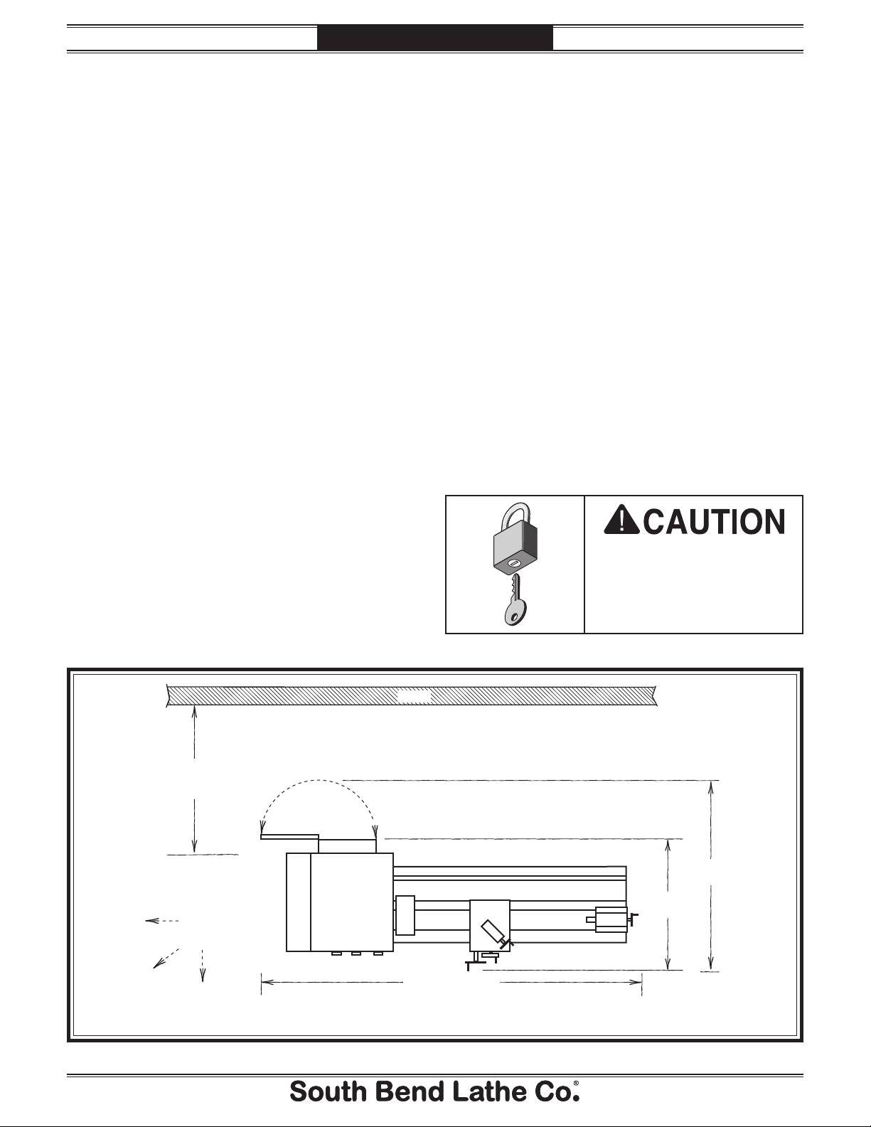
Wall
Electrical
Min. 30"
for Maintenance
Keep
Workpiece
Loading Area
Unobstructed
Cabinet
Lathe
Children or untrained
people may be seriously
injured by this machine.
Install machine in an
access restricted location.
54"
38"
(Drawing Not To Scale)
Figure 12. Space required for full range of movement.
79" (SB1049)
90" (SB1050)
-21-
13" Heavy 13® Gearhead Lathe
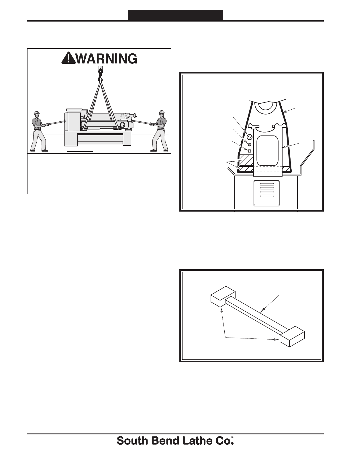
Lifting & Moving
PREPARATION
5. Position hardwood blocks under each end
of the bed as shown in Figure 13. This
will keep the lifting straps away from the
leadscrew, feed rod, and spindle rod to
prevent bending them during lifting.
(Looking at Lifting Setup from Tailstock End)
Leadscrew
Feed Rod
For Machines Mfg. Since 5/11
To Power Lifting Equipment
Control
Rod
Lifting
Strap
Lathe
Bed
This machine and its parts are heavy! Serious
personal injury may occur if safe moving
methods are not used. To reduce the risk of a
lifting or dropping injury, ask others for help,
and use power equipment and guide rods.
Do not attempt to lift or move this lathe without
using the proper lifting equipment (such as
forklift or crane) or the necessary assistance from
other people. Each piece of lifting equipment
must be rated for at least 25% more than the
shipping weight of your lathe to support dynamic
loads that may be applied while lifting. Refer to
Things You'll Need on Page 16 for details.
To lift and move the lathe:
1. Remove the shipping crate top and sides,
then remove the small components from the
shipping pallet.
2. Move the lathe to its prepared location while
it is still attached to the shipping pallet.
Hardwood Blocks
and Planks
Positioned as
Required to
Prevent Lifting
Straps from
Bending
Leadscrew
Figure 13. Lifting setup to keep straps from bending
leadscrew or rods.
Note: Fasten a center support between the
hardwood blocks so that they will stay
spread apart and in place when lifting (see
the example in Figure 14).
Center
Support
3. Unbolt the lathe from the shipping pallet
4. To balance the load for lifting, move the
tailstock and carriage to the extreme right
end of the bedway, then lock them in place.
Note: Before attempting to move the carriage,
make sure the carriage lock is loose, the half
nut is disengaged, and the power feed is
disengaged (feed selection lever).
-22-
Hardwood
Blocking
Figure 14. Example of blocking center support.
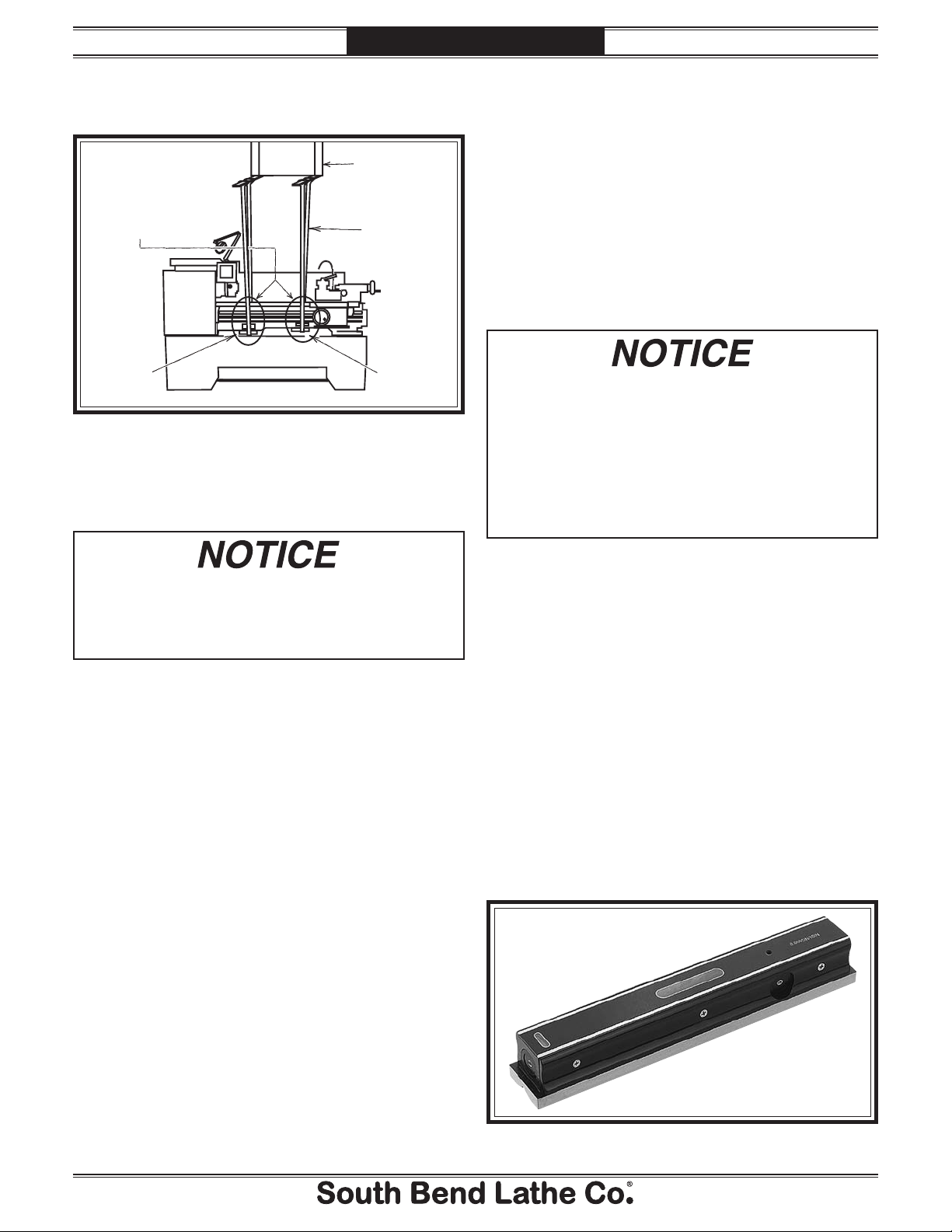
For Machines Mfg. Since 5/11 13" Heavy 13® Gearhead Lathe
PREPARATION
6. Attach the lifting straps to the power lifting
equipment (see Figure 15 for an example).
Leveling & Mounting
You must level your machine and either use
Use Blocks as Necessary
to Space Straps Away
from Control Rod,
Feed Rod, and Leadscrew
to Prevent Bending when
the Lathe is Lifted
Power Lifting
Equipment
Lifting
Straps
the included foot pads and leveling hardware or
bolt and shim your lathe to the floor. Because
mounting your lathe to the floor with permanent
hardware is an optional step and floor materials
may vary, f loor mounting hardware is not
included.
Leveling
Hardwood
Blocking
Figure 15. Example of lathe setup for lifting.
Hardwood
Blocking
7. At each end of the lathe, have assistants
connect guide rods to safely keep the lathe
from swaying or tipping during lifting.
When lifting the lathe with straps, the load
will be top heavy. Take extra care to keep the
load balanced vertically and only lift the lathe
far enough to remove the shipping pallet.
8. Raise the lathe a couple of inches and check
the balance of the load.
— If the load is not safely balanced,
immediately lower the lathe and resolve
the issue before attempting to lift it
again.
For accurate turning results and to prevent
warping the cast iron bed and ways, the lathe
bedways MUST be leveled from side-to-side
and from front-to-back on both ends.
Re-check the bedways 24 hours after
installation, two weeks after that, and then
annually to make sure they remain level.
Leveling machinery helps precision components,
such as bedways, remain straight and flat during
the lifespan of the machine. Components on a
machine that is not level may slowly twist due to
the dynamic loads placed on the machine during
operation.
For best results, use a precision level that
is at least 12" long and sensitive enough to
show a distinct movement when a 0.003" shim
(approximately the thickness of one sheet of
standard newspaper) is placed under one end of
the level.
9. Raise the lathe enough to clear the shipping
pallet, carefully remove the pallet, then
lower the lathe into position.
See the figure below for an example of a high
precision level.
Figure 16. Example of a precision level.
-23-
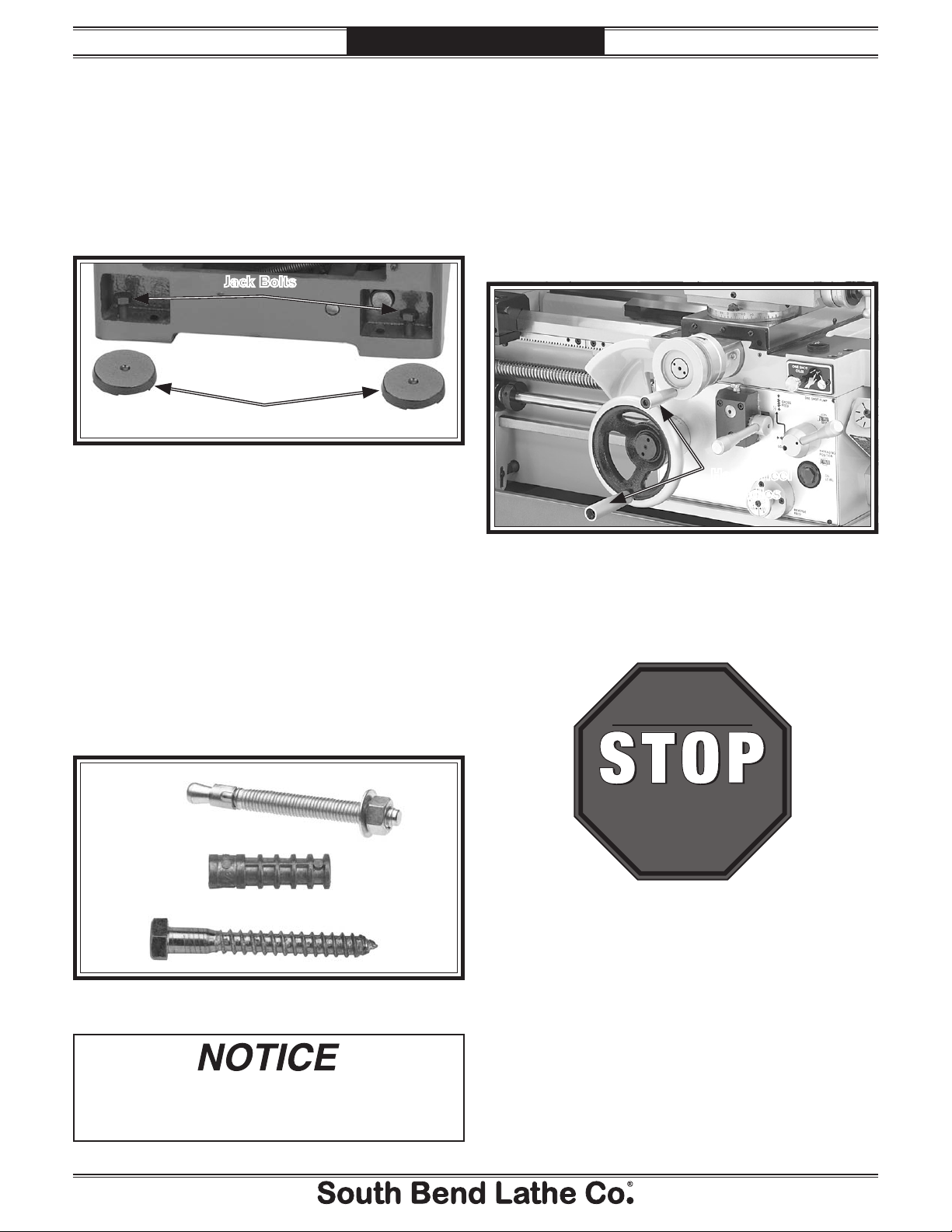
13" Heavy 13® Gearhead Lathe
PREPARATION
To level the machine, use a precision level to
make sure the bedways are level from side-toside and from front-to-back.
— If using the included leveling pads (see
Figure 17), place them under the six
leveling jack bolt locations, then adjust
the bolts to level the lathe.
Jack Bolts
Pads
Figure 17. Leveling pads and screws.
— If using mounting hardware that does not
allow for adjustment, level the lathe by
placing metal shims between the lathe
base and the floor before bolting it down.
For Machines Mfg. Since 5/11
Assembly
With the exception of the handwheel handles, the
lathe is shipped fully assembled.
To install the handwheel handles, thread the
large handle into the carriage handwheel and the
small handle into the cross slide handwheel, as
shown in Figure 19.
Handwheel
Handles
Figure 19. Handwheel handles installed.
Bolting to Concrete Floors
Lag screws and anchors, or anchor studs
(below), are two popular methods for bolting
machinery to a concrete floor. We suggest you
research the many options and methods for
mounting your machine and choose the best one
for your specific application.
Anchor
Stud
Lag Screw
and Anchor
Figure 18. Common types of fasteners for bolting
machinery to concrete floors.
Most electrical codes require that machines
connected to the power source by fixed
conduit MUST be secured to the floor.
Lubricating Lathe
GEARBOXES MUST
BE FILLED WITH OIL!
OIL MAY NOT BE
SHIPPED WITH MACHINE!
Refer to Lubrication Section
for Correct Oil Type.
The headstock, quick-change gearbox, and apron
oil reservoirs must have the proper amount of oil
in them before the lathe can be operated for the
first time.
Damage caused to the bearings and gears from
running the lathe without oil in the reservoirs
will not be covered under warranty. Refer to the
Lubrication section, beginning on Page 66, for
details on how to check, add oil, and prime the
headstock oil pump.
-24-
 Loading...