


DAB1
DISTRIBUTED AUDIO SYSTEM
INSTRUCTION MANUAL
Important Safety Information
IMPORTANT: Read all of these instructions before you operate your DAB1, and save these instructions for later use.
1. Read Instructions — All these safety and operating instructions should be read before you operate the unit.
2. Retain Instructions — These safety and operating instructions should be retained for future reference.
3. Heed Warnings — All warnings on the unit and in the operating instructions should be adhered to.
4. Follow Instructions — All operating and use instructions should be followed.
5. Water and Moisture — The unit should not be used near water — for example, near a bathtub, washbowl, kitchen sink, laundry tub, in a wet basement, or near a swimming pool, and the like.
6. Carts and Stands — The unit should be used only with a cart or stand that is recommended by the manufacturer.
• A unit and cart combination should be moved with care. Quick stops, excessive force, and uneven surfaces may cause the unit and cart combination to overturn.
7.CAUTION: To prevent electric shock, do not use the DAB1’s polarized plug with an extension cord, receptacle, or other outlets unless the blades can be fully inserted to prevent blade exposure.
8. Ventilation — The unit should be situated so that its location or position does not interfere with its proper ventilation. For example, the unit should not be situated on a bed, sofa, rug, or similar surface that may block the ventilation openings; or be placed in a built-in installation, such as a bookcase or cabinet, that may impede the flow of air through the ventilation openings.
9. Heat — The unit should be situated away from heat sources such as radiators, heat registers, stoves, or other appliances (including other audio components) that produce heat.
10. Power Sources — The unit should be connected to a power supply only of the type described in the operating instructions or as marked on the unit.
11. Grounding or Polarization — Precautions should be taken so that the grounding or polarization means of the unit is not defeated.
12. Power Cord Protection — Power supply cords should be routed so that they are not likely to be walked on or pinched by items placed upon or against them, paying particular attention to cords at plugs, convenience receptacles, and the point where they exit from the controller.
13. C l e a n i n g — The unit should be cleaned only as recommended by the manufacturer.
14. Non-Use Periods — The power cord of the unit should be unplugged from the outlet when left unused for a long period of time.
15. Object and Liquid Entry — Care should be taken so that objects do not fall and liquids are not spilled into the enclosure through openings.
16. Damage Requiring Service — The unit should be serviced by qualified service personnel when:
a.The power-supply cord or the plug has been damaged; or
b.Objects have fallen or liquid has been spilled into the unit; or
c.The unit has been exposed to rain; or
d.The unit does not appear to operate normally or exhibits a marked change in performance; or
e.The unit has been dropped or the enclosure damaged.
17. Servicing — The user should not attempt to service the unit beyond that described in the operating instructions. All other servicing should be referred to qualified service personnel.
|
|
|
|
|
|
|
|
|
|
|
|
|
|
|
|
|
|
|
|
|
|
|
|
|
|
|
|
|
|
|
|
|
|
|
|
|
|
|
|
|
|
|
|
|
|
|
|
|
|
|
|
|
|
|
|
|
|
|
|
|
|
|
|
|
|
|
|
|
|
|
|
|
|
|
|
|
|
|
|
|
|
|
|
|
|
|
|
|
|
|
|
|
|
|
|
|
|
|
|
|
|
|
|
|
|
|
|
|
|
|
|
CAUTION: TO REDUCE THE RISK OF ELECTRIC |
|
|
|
|
TO PREVENT FIRE OR SHOCK |
||||||||||
|
|
|
|
HAZARD, DO NOT EXPOSE THIS APPLI- |
|||||||||||
SHOCK, DO NOT REMOVE COVER OR |
|
|
|
|
ANCE TO RAIN OR MOISTURE. THE |
||||||||||
BACK. NO USER-SERVICEABLE PARTS |
|
|
|
|
APPLIANCE WHALL NOT BE EXPOSED |
||||||||||
INSIDE. REFER SERVICING TO AUTHO- |
|
|
|
|
TO DRIPPING OR SPLASHING. NO |
||||||||||
RIZED SERVICE PERSONNEL. |
|
|
|
|
|
OBJECTS FILLED WITH LIQUIDS SHALL |
|||||||||
|
|
|
|
|
|
|
|
|
|
BE PLACED ON THE APPLIANCE. |
|
||||
The lightning flash with arrowhead |
|
|
The |
exclamation |
point within |
||||||||||
symbol, |
within an |
equilateral |
|
|
an |
equilateral |
triangle |
is |
|||||||
triangle, |
is |
intended |
to alert |
the |
|
|
intended to alert the user to the |
||||||||
user to the presence of uninsulated |
|
|
presence of important operat- |
||||||||||||
|
|
ing |
|
and |
maintenance |
||||||||||
dangerous |
voltage |
within |
the |
|
|
|
|||||||||
|
|
(servicing) |
instructions in |
the |
|||||||||||
product’s enclosure that may be of |
|
|
|||||||||||||
|
|
literature |
accompanying |
the |
|||||||||||
sufficient magnitude to constitute a |
|
|
|||||||||||||
|
|
appliance. |
|
|
|
||||||||||
risk of electric shock to persons. |
|
|
|
|
|
||||||||||
|
|
|
|
|
|
|
|
||||||||
3

|
DAB1 DISTRIBUTED AUDIO SYSTEM |
TABLE OF CONTENTS |
|
Important Safety Information . . . . . . . . . . . . . . . . . . . . . . . |
. . . . . . . . . . . . . . . . . . . . . . . . . . . 3 |
Introduction . . . . . . . . . . . . . . . . . . . . . . . . . . . . . . . . . . . |
. . . . . . . . . . . . . . . . . . . . . . . . . . 6 |
DAB1 Features . . . . . . . . . . . . . . . . . . . . . . . . . . . . . . . . . . |
. . . . . . . . . . . . . . . . . . . . . . . . . . 6 |
Box Contents . . . . . . . . . . . . . . . . . . . . . . . . . . . . . . . . . . . |
. . . . . . . . . . . . . . . . . . . . . . . . . . 7 |
Unpacking . . . . . . . . . . . . . . . . . . . . . . . . . . . . . . . . . . . . |
. . . . . . . . . . . . . . . . . . . . . . . . . . 7 |
Placement . . . . . . . . . . . . . . . . . . . . . . . . . . . . . . . . . . . . . |
. . . . . . . . . . . . . . . . . . . . . . . . . . 7 |
System Overview . . . . . . . . . . . . . . . . . . . . . . . . . . . . . . . . |
. . . . . . . . . . . . . . . . . . . . . . . . . . 8 |
Front and Rear Panel Views . . . . . . . . . . . . . . . . . . . . . . . . . |
. . . . . . . . . . . . . . . . . . . . . . . . . 10 |
Connecting the DAB1 . . . . . . . . . . . . . . . . . . . . . . . . . . . . . |
. . . . . . . . . . . . . . . . . . . . . . 11 – 17 |
Power Connections, Replacing the AC Fuse . . . . . . . . . . . . . . . . . . |
. . . . . . . . . . . . . . . . . . . . . . . . . . . . . .11 |
Antenna Connections . . . . . . . . . . . . . . . . . . . . . . . . . . . . . . . . . |
. . . . . . . . . . . . . . . . . . . . . . . . . . . . . .11 |
Source Input Connections . . . . . . . . . . . . . . . . . . . . . . . . . . . . . . |
. . . . . . . . . . . . . . . . . . . . . . . . . . . . . .12 |
Source Output Connections . . . . . . . . . . . . . . . . . . . . . . . . . . . . |
. . . . . . . . . . . . . . . . . . . . . . . . . . . . . .12 |
Speaker Connections . . . . . . . . . . . . . . . . . . . . . . . . . . . . . . . . |
. . . . . . . . . . . . . . . . . . . . . . . . . . . . . .12 |
Zone Line Output Connections . . . . . . . . . . . . . . . . . . . . . . . . . . |
. . . . . . . . . . . . . . . . . . . . . . . . . . . . . .13 |
Line Output Fixed/Variable Switch . . . . . . . . . . . . . . . . . . . . |
. . . . . . . . . . . . . . . . . . . . . . . . . . . . . .13 |
Connecting a High-Power Amplifier in a Zone . . . . . . . . . . . . . |
. . . . . . . . . . . . . . . . . . . . . . . . . . . . . .15 |
Using a Multi-Channel Amplifier for Sub-Zone Expansion . . . . . . . . |
. . . . . . . . . . . . . . . . . . . . . . . . . . . . . .15 |
IR Connections . . . . . . . . . . . . . . . . . . . . . . . . . . . . . . . . . . . . . |
. . . . . . . . . . . . . . . . . . . . . . . . . . . . . .15 |
Control Output, Control Input and Sync Connections . . . . . . . . . . . |
. . . . . . . . . . . . . . . . . . . . . . . . . . . . . .16 |
Paging Connections . . . . . . . . . . . . . . . . . . . . . . . . . . . . . . . . . . |
. . . . . . . . . . . . . . . . . . . . . . . . . . . . . .17 |
RS-232 Connection . . . . . . . . . . . . . . . . . . . . . . . . . . . . . . . . . . |
. . . . . . . . . . . . . . . . . . . . . . . . . . . . . .17 |
Keypad Controllers . . . . . . . . . . . . . . . . . . . . . . . . . . . . . . |
. . . . . . . . . . . . . . . . . . . . . . 18 – 24 |
C4630 SE Main and Numeric Keypads . . . . . . . . . . . . . . . . . . . . |
. . . . . . . . . . . . . . . . . . . . . . . . . . . . . .18 |
DAB1 Keypad . . . . . . . . . . . . . . . . . . . . . . . . . . . . . . . . . . . . . |
. . . . . . . . . . . . . . . . . . . . . . . . . . . . . .22 |
Keypad Connections . . . . . . . . . . . . . . . . . . . . . . . . . . . . . . . . . |
. . . . . . . . . . . . . . . . . . . . . . . . . . . . . .24 |
External Keypad Power . . . . . . . . . . . . . . . . . . . . . . . . . . . . . . . |
. . . . . . . . . . . . . . . . . . . . . . . . . . . . . .24 |
DAB1 IR Remote control . . . . . . . . . . . . . . . . . . . . . . . . . . . |
. . . . . . . . . . . . . . . . . . . . . . . . . 25 |
DAB1 Front Panel Controls and Indicators . . . . . . . . . . . . . . . |
. . . . . . . . . . . . . . . . . . . . . . 26 – 27 |
Sonance Control Manager Software . . . . . . . . . . . . . . . . . . . |
. . . . . . . . . . . . . . . . . . . . . . 27 – 33 |
Installing the Sonance Control Manager Software . . . . . . . . . . . . . |
. . . . . . . . . . . . . . . . . . . . . . . . . . . . . .27 |
Transferring System Information and Programming to the DAB1 . . . . |
. . . . . . . . . . . . . . . . . . . . . . . . . . . . . .28 |
Updating the Sonance Control Manager Software and Firmware . . . |
. . . . . . . . . . . . . . . . . . . . . . . . . . . . . .28 |
Creating a New DAB1 System . . . . . . . . . . . . . . . . . . . . . . . . . . |
. . . . . . . . . . . . . . . . . . . . . . . . . . . . . .30 |
Setting Up a Zone . . . . . . . . . . . . . . . . . . . . . . . . . . . . . . . . . . . |
. . . . . . . . . . . . . . . . . . . . . . . . . . . . . .32 |
Setting Up Sources . . . . . . . . . . . . . . . . . . . . . . . . . . . . . . . . . . |
. . . . . . . . . . . . . . . . . . . . . . . . . . . . . .33 |
4

DAB1 DISTRIBUTED AUDIO SYSTEM |
|
Programming DAB1 Keypad Macros . . . . . . . . . . . . . . . . . . . . . . . . . . . . . . . . . . . . . . . . . |
34 – 45 |
Device Screen . . . . . . . . . . . . . . . . . . . . . . . . . . . . . . . . . . . . . . . . . . . . . . . . . . . . . . . . . . . . . . . |
. . . .34 |
General Macro Programming Notes . . . . . . . . . . . . . . . . . . . . . . . . . . . . . . . . . . . . . . . . . . . . . . . . . |
. . . .34 |
Building Macros . . . . . . . . . . . . . . . . . . . . . . . . . . . . . . . . . . . . . . . . . . . . . . . . . . . . . . . . . . . . . . |
. . . .35 |
The Macro Editor Screen . . . . . . . . . . . . . . . . . . . . . . . . . . . . . . . . . . . . . . . . . . . . . . . . . . . . . . . . |
. . . .36 |
Macro Command Types . . . . . . . . . . . . . . . . . . . . . . . . . . . . . . . . . . . . . . . . . . . . . . . . . . . . . . . . . |
. . . .36 |
IR Commands . . . . . . . . . . . . . . . . . . . . . . . . . . . . . . . . . . . . . . . . . . . . . . . . . . . . . . . . . . . . . |
. . . .36 |
Adding IR Codes to the User IR Library with the OptiLinQ® IR Learner . . . . . . . . . . . . . . . . . . . . |
. . . .39 |
Internal Commands . . . . . . . . . . . . . . . . . . . . . . . . . . . . . . . . . . . . . . . . . . . . . . . . . . . . . . . . . |
. . . .41 |
Status Test Command . . . . . . . . . . . . . . . . . . . . . . . . . . . . . . . . . . . . . . . . . . . . . . . . . . . . . . . . |
. . . .42 |
Time Delay Command . . . . . . . . . . . . . . . . . . . . . . . . . . . . . . . . . . . . . . . . . . . . . . . . . . . . . . . |
. . . .42 |
RS-232 (Serial) Commands . . . . . . . . . . . . . . . . . . . . . . . . . . . . . . . . . . . . . . . . . . . . . . . . . . . . |
. . . .43 |
Stop Macro Command . . . . . . . . . . . . . . . . . . . . . . . . . . . . . . . . . . . . . . . . . . . . . . . . . . . . . . . |
. . . .44 |
Repeat Steps Command . . . . . . . . . . . . . . . . . . . . . . . . . . . . . . . . . . . . . . . . . . . . . . . . . . . . . . |
. . . .44 |
Toggle IR Code Command . . . . . . . . . . . . . . . . . . . . . . . . . . . . . . . . . . . . . . . . . . . . . . . . . . . . |
. . . .45 |
Controlling the DAB1 via RS-232 (Serial Control) . . . . . . . . . . . . . . . . . . . . . . . . . . . . . . . . |
45 – 48 |
DAB1 Serial Protocol . . . . . . . . . . . . . . . . . . . . . . . . . . . . . . . . . . . . . . . . . . . . . . . . . . . . . . . . . . . |
. . . .45 |
DAB1 Serial Commands . . . . . . . . . . . . . . . . . . . . . . . . . . . . . . . . . . . . . . . . . . . . . . . . . . . . . . . . . |
. . . .46 |
Serial Control of DAB1s in Multi-Unit Systems . . . . . . . . . . . . . . . . . . . . . . . . . . . . . . . . . . . . . . . . . . |
. . . .47 |
DAB1 Status Queries . . . . . . . . . . . . . . . . . . . . . . . . . . . . . . . . . . . . . . . . . . . . . . . . . . . . . . . . . . . |
. . . .47 |
Simulate Button Press Serial Commands . . . . . . . . . . . . . . . . . . . . . . . . . . . . . . . . . . . . . . . . . . . . . . |
. . . .48 |
Using the DAB1 with Sonance Navigator K2 and K1 Programmable Keypads . . . . . . . . . . . . . . . 49 – 50 Wiring K2 and K1 Keypad Connections . . . . . . . . . . . . . . . . . . . . . . . . . . . . . . . . . . . . . . . . . . . . . . . . . .49 Powering K1 and K2 Keypads . . . . . . . . . . . . . . . . . . . . . . . . . . . . . . . . . . . . . . . . . . . . . . . . . . . . . . . .49 Using DAB1 Internal Macros with K1/K2 Programmable Keypads . . . . . . . . . . . . . . . . . . . . . . . . . . . . . . . .50
Expanded Control Features . . . . . . . . . . . . . . . . . . . . . . . . . . . . . . . . . . . . . . . . . . . . . . . |
50 |
– 51 |
DAB1 Extra Command Macros . . . . . . . . . . . . . . . . . . . . . . . . . . . . . . . . . . . . . . . . . . . . . . . . . . . . |
. . |
. .50 |
Triggering DAB1 Extra Command Macros From the K1 and K2 . . . . . . . . . . . . . . . . . . . . . . . . . . . . . . |
. . |
. .51 |
Getting System Configuration Information . . . . . . . . . . . . . . . . . . . . . . . . . . . . . . . . . . . . . |
. . |
. . 52 |
Generating a System Configuration Report . . . . . . . . . . . . . . . . . . . . . . . . . . . . . . . . . . . . . . . . . . . . |
. . |
. .52 |
Finding RS-232 Commands in Macros . . . . . . . . . . . . . . . . . . . . . . . . . . . . . . . . . . . . . . . . . . . . . . . |
. . . |
.53 |
Appendix 1: “Party Mode” . . . . . . . . . . . . . . . . . . . . . . . . . . . . . . . . . . . . . . . . . . . . . . . |
54 |
– 57 |
Programming the DAB1 to turn all zones OFF in systems incorporating multiple DAB1s . . . . . . . . . . . . . . |
54 – 55 |
|
Programming a K2 Keypad to Activate Party Mode in a DAB1 System . . . . . . . . . . . . . . . . . . . . . . . . . |
56 – 57 |
|
Appendix 2: Programming EX T R A CO M M A N D Volume Control Macros . . . . . . . . . . . . . . . . . . . . |
. . . |
. 58 |
Specifications . . . . . . . . . . . . . . . . . . . . . . . . . . . . . . . . . . . . . . . . . . . . . . . . . . . . . . . . |
59 |
– 60 |
Troubleshooting . . . . . . . . . . . . . . . . . . . . . . . . . . . . . . . . . . . . . . . . . . . . . . . . . . . . . . |
61 |
– 64 |
5
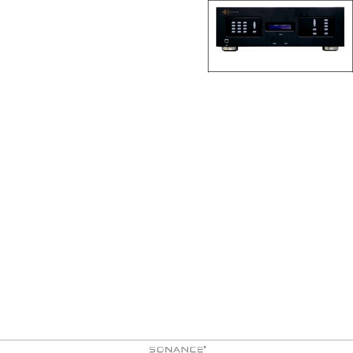
Introduction
Thank you for purchasing the Sonance DAB1 Distributed Audio System. The DAB1 lets you listen to any of four different audio sources (including a built-in FM/AM tuner) in up to six different rooms (zones) at the same time. When programmed with the included Sonance Control Manager programming software and used with available Sonance keypad controllers and the included IR remote control, the DAB1 gives you easy, logical control of both the system’s audio sources and the sound in each room. The Control Manager software even lets you
program the DAB1 with macros that allow complex functions (like turning the system ON, selecting a source, setting the volume and other audio parameters and starting the music in a specific room) to be accomplished with a single button push. There is also a “PARTY MODE” that gives you control of the whole house from a single location, and a Paging function for communication between rooms. For more sophisticated systems, the DAB1 has an RS-232 communications port that can integrate it with whole-home control systems that control such things as lights, temperature and security systems.
The DAB1 is controlled by Sonance DAB1 Keypads, C4630 SE Main and Numeric Keypads and Sonance Navigator® K1 and K2 Keypad Controllers (all available separately). It can also be controlled by the included IR remote, either via its built-in front-panel IR receiver or via IR receivers in connected keypads. The DAB1 can also be serial-controlled by 3rdparty control systems via its RS-232 connection.
DAB1 Features
Audio:
•Four-source, six-zone, distributed audio matrix and control system
•Four source inputs (4 external, or 3 external + internal tuner)
•Six zone speaker-level stereo outputs (30 watts/ch RMS x 12 @ 8 ohms)
•Four buffered line-level audio outputs that can be used to bridge to additional DAB1 units or as record outputs
•Six zone line-level audio outputs (fixed or variable)
•Built-in FM/AM tuner with 12 presets
•Line-level source inputs are adjustable for source-to-source input level matching
•Software configuration of individual zone turn-on volume, maximum volume, paging volume, treble, bass and balance
•Paging Input connections
Control:
•Connections for up to six Sonance keypad controllers (expandable)
•Sonance Control Manager software CD included
•Extensive macro capability
•RS-232 port for external control
•Six zone-specific IR outputs
•Four Common IR outputs
•Four Programmed IR outputs for controlling specific source components
•IR Link for distributing IR signals in expanded systems with multiple DAB1 Controllers
•Sync connections link multiple DAB1 units for unified control in expanded systems
•Upgradeable firmware lets you easily add new features when they become available
•Included IR remote control
6

DAB1 DISTRIBUTED AUDIO SYSTEM
Box Contents
Your DAB1 Home Audio System box should contain the following items:
(1) Sonance DAB1 Distributed Audio System |
(1) |
Dipole FM Antenna |
|
(2) |
Rack-mount ears |
(1) |
300-ohm/75-ohm Antenna Adapter |
(6) |
Removable 4-Wire Speaker Connectors |
(1) |
F-Connector Antenna Adapter |
(1) |
IEC Power cord (115V version only) |
(1) |
AM Antenna |
(1) |
USB Connection Cable |
(1) |
Sonance Control Manager software CD-ROM |
Unpacking
Save the shipping carton and polystyrene inserts so you can safely transport your DAB1 in the future. Before you install the DAB1, locate the serial number on the rear panel and note it here for future reference: S/N:
Placement
The DAB1 should be installed at the main termination of all audio system wire and cable runs. The system’s source components (CD player, iPort™/iPod®, music server, satellite radio receiver, etc) should also be installed at this location.
The DAB1 may be placed on a shelf in a wall unit in a media room or rack-mounted in a 19” standard equipment rack in a dedicated equipment room. When determining the location for the system components consider having access to the system for loading CDs, DVDs and other media. You should also make provisions for easy access if the components should require service.
Ventilation and Airflow
The DAB1 must be placed in a location that will allow sufficient airflow for ventilation. Leave space above the unit, per the safety instructions, to allow the unit to “breathe” through the vent holes on the top and bottom of the unit. Blocking the vent holes will inhibit airflow through the unit and can cause damage to the DAB1. If necessary, install a fan to maintain enough airflow to ensure adequate convection cooling.
Be sure to leave plenty of room for wire and cable. The amount of wire used in this type of installation can quickly fill the empty space around the DAB1 and act as a thermal insulator. This can create an undesirable thermal condition that could cause the unit to shut down. Leaving extra room for wire and cable is also a good idea if you ever want to upgrade the system or if it ever needs service.
General Placement Guidelines
•Keep the DAB1 out of direct sunlight and away from windows that could let in rain.
•Place the DAB1 away from heat sources such as hot air ducts or radiators.
•Do not place the DAB1 directly on carpet that could interfere with airflow into its bottom vent openings.
• If you stack your components, it is better to place the DAB1 above or alongside your other components. When driven hard, the DAB1 creates heat that can affect components stacked on top of it.
7

DAB1 DISTRIBUTED AUDIO SYSTEM
Shelf-Mounting
IMPORTANT: Never remove the feet when mounting the unit on a shelf. Doing so may cause damage to the DAB1 and other components due to heat being trapped.
Rack-Mounting
Use the included rack-mount adapters to rack-mount the DAB1. Use the four chassis screws already secured to each side of the DAB1 to attach the rack adapters. The DAB1 chassis has been specially designed to provide support when using the rack adapters. The adapters have also been designed to match the DAB1’s front panel for a clean, professional look. The DAB1 requires 3U of rack space. When rack-mounting the DAB1, leave sufficient space between the unit and other components in the rack to allow proper airflow for ventilation. Sonance recommends using a rack vent spacer above the unit to improve airflow.
System Overview
The DAB1 Distributed Audio System has features and capabilities that will meet the demands of an extremely wide variety of applications. It can be a simple background music system, serve as the preamp/controller for a powerful foreground music system, or it can be integrated as a sub-system in a complex whole-house automation and control package. Understanding the DAB1’s features and capabilities is one of the keys to creating a great system.
In all stages of system design and installation you should plan ahead. Put the entire design |
down on |
paper |
so you |
||
can verify |
all aspects of it before beginning the installation. With a |
system that can literally leave holes |
in the walls if |
||
something |
hasn’t been properly planned or tested, we recommend |
setting-up, programming |
and testing the |
system’s |
|
components as they will be used before actually performing the installation. This will help insure that the system will work as designed and that you have all the necessary parts and components on hand prior to beginning the installation.
Always plan for system expansion in terms of both size and flexibility. Anticipating system expansion by carefully planning what the initial installation is going to be and what the system requirements might be as upgrades are incorporated can save you time, money and aggravation.
Control Considerations
The DAB1 is designed to be controlled by the DAB1 keypad, the C4630 SE Main Keypad, or Sonance Navigator® K1 and K2 keypads. The included IR remote can operate via the DAB1’s front-panel IR receiver, and it can also operate via external IR receivers connected to the DAB1 via its keypad controllers. The C4630 SE Main Keypad has a built-in holster that can accommodate a Sonance FSMR1 or MR1 IR receiver (see page 19). When planning your system be sure to include all of your control needs along with your audio requirements.
Head End Considerations
Reserve as much space as possible for the DAB1 and source components — an equipment closet with rear access to the components is ideal. At the very least, reserve enough space in the equipment rack or wall unit to properly install all components, leaving plenty of room for wire, ventilation, possible future expansion and room to work. ( c o n t i n u e d o n p a ge 11 )
8
DAB1 DISTRIBUTED AUDIO SYSTEM
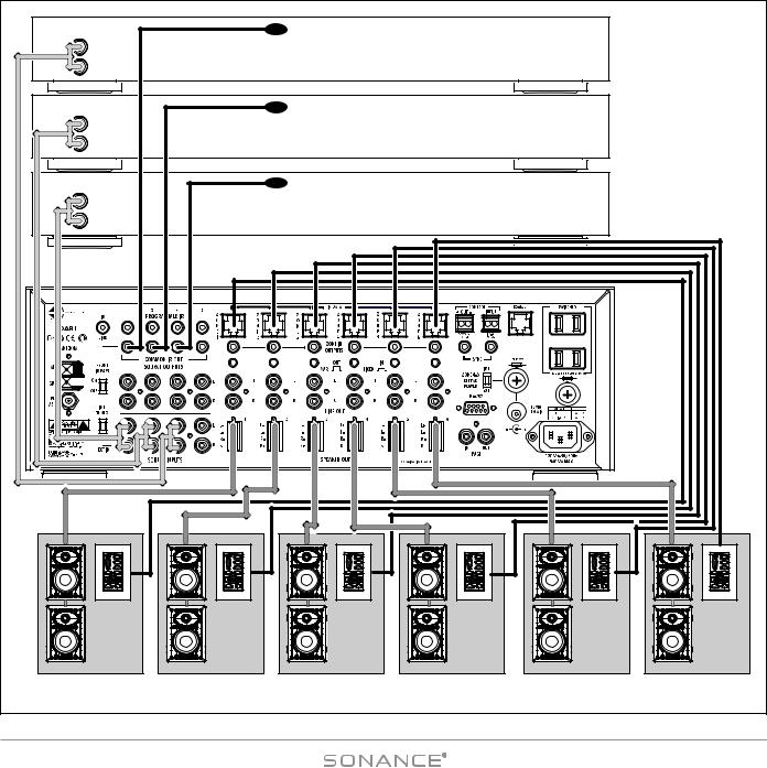
IR Emitter |
Source 3 (Satellite Radio) |
(on front of unit) |
|
L |
|
|
|
|
|
|
|
|
|
R |
|
|
|
|
|
|
|
|
|
|
|
|
|
|
IR Emitter |
Source 2 (AM/FM Tuner) |
|
|
|
L |
|
|
|
|
(on front of unit) |
|
|
|
|
R |
|
|
|
|
|
|
|
|
|
|
|
|
|
|
IR Emitter |
Source 1 (CD Changer) |
|
|
|
L |
|
|
|
|
(on front of unit) |
|
|
|
|
R |
|
|
|
|
|
|
|
|
|
^ |
|
|
^ |
|
^ |
^ |
^ |
|
^ |
^ |
|
|
^ |
|
^ |
^ |
^ |
|
^ |
^ |
= |
^ |
^ |
= ^ |
^ = ^ |
^ = ^ |
^ = |
^ |
^ = ^ |
Zone |
Zone |
Zone |
Zone |
Zone |
Zone |
||||
1 |
|
2 |
3 |
4 |
5 |
6 |
|||
|
|
|
|
|
Figure 2: Typical DAB1 System |
|
|
|
|
9
|
|
|
|
|
|
DAB1 DISTRIBUTED AUDIO SYSTEM |
|||||
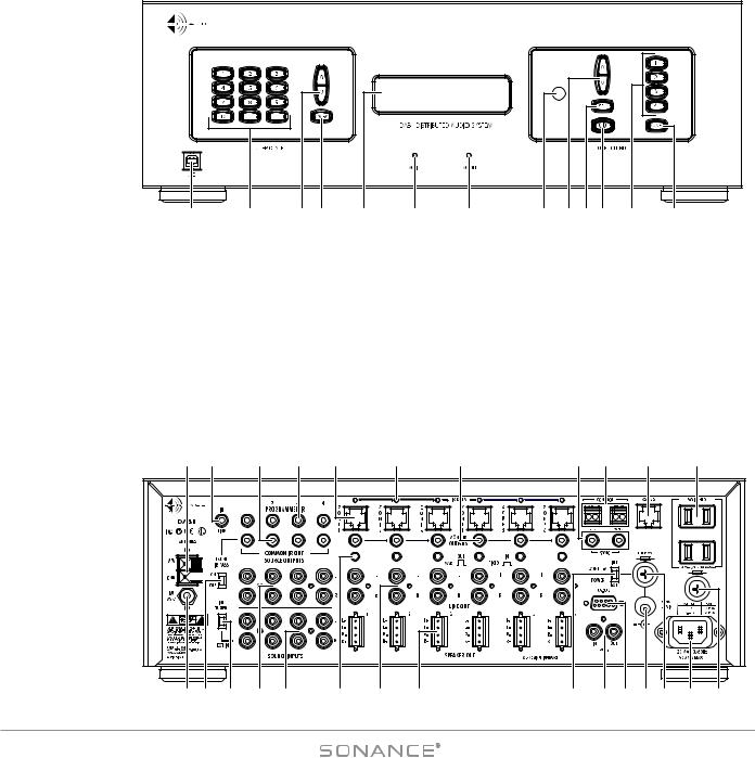
Figure 3: |
|
|
|
|
|
|
|
|
|
|
|
DAB1 |
|
|
|
|
|
|
|
|
|
|
|
Front and |
|
|
|
|
|
|
|
|
|
|
|
Rear Panels |
|
|
|
|
|
|
|
|
|
|
|
1 |
2 |
3 |
4 |
5 |
6 |
7 |
8 |
9 |
10 11 |
12 |
13 |
1. |
USB Port (Page 25) |
14. |
AM Antenna Connector (Page 11) |
27. |
Source 1 INT TUNER/EXT IN Switch (Page 12) |
|||
2. |
Tuner Preset Buttons (Page 26) |
15. |
IR Link Jack (Page 15) |
28. |
Source 1 – 4 Output Jacks (Page 12) |
|||
3. |
Tuner UP/DOWN Buttons (Page 26) |
16. |
Common IR Out Jacks 1 – 4 (Page 15) |
29. |
Source 1 – 4 Input Jacks (Page 12) |
|||
4. |
FM/AM Selector Button (Page 26) |
17. |
Programmed IR Out Jacks 1 – 4 (Page 15) |
30. |
Zone 1 – 6 Line Output Fixed/Variable Switches (Page 13) |
|||
5. |
System Status/Tuner Display (Page 26) |
18. |
Zone 1 |
– 6 |
Keypad Controller Ports (Page 24) |
31. |
Zone 1 – 6 Line Output Jacks (Page 13) |
|
6. |
ACTIVE Indicator (Page 26) |
19. |
Zone 1 |
– 6 |
IR Data LEDs (Page 15) |
32. |
Zone 1 – 6 |
Speaker Output Terminals (Page 12) |
7. |
AC ON Indicator (Page 26) |
20. |
Zone 1 |
– 6 |
IR Local IR Output Jacks (Page 16) |
33. |
Zone 4 – 6 |
Keypad Power Switch (Page 24) |
8. |
IR Receiver (Page 26) |
21. |
Sync Input/Output Jacks (Page 16) |
34. |
Paging Input/Output Jacks (Page 17) |
|||
9. |
Zone Function Value Buttons (Page 26) |
22. |
12V Control Voltage Input/Output (Page 16) |
35. |
RS-232 Connection (Page 17) |
|||
10. |
Zone Function Select Button (Page 26) |
23. |
RS-422 Terminal (Page 17) |
36. |
Zone 4 – 6 |
External Keypad Power Connection (Page 24) |
||
11. |
Zone Power OFF Button (Page 27) |
24. |
Switched AC Accessory Outlets (Page 11) |
37. |
Zone 4 – 6 |
External Keypad Power Fuse Holder (Page 24) |
||
12. |
Source Select Buttons (Page 27) |
25. |
FM Antenna Connector (Page 11) |
38. |
Power Cord Connection (Page 11) |
|||
13. |
Zone Select Button (Page 27) |
26. |
Front IR Pass Switch (Page 15) |
39. |
AC Fuse Holder (Page 11) |
|||
14 |
15 |
|
16 |
|
17 |
18 |
19 |
20 |
21 |
22 |
|
23 |
24 |
|
25 |
26 |
27 |
28 |
29 |
|
30 |
31 |
32 |
33 |
34 |
35 |
36 37 |
38 |
39 |
10
DAB1 DISTRIBUTED AUDIO SYSTEM
Zone Considerations (continue d fro m pa ge 8)
What is the performance requirement for each zone? Some zones may only require a keypad controller and speakers. Some may need an additional IR receiver. One may need a more flexible keypad and a high-power amplifier. A master suite may require a multi-channel amplifier to distribute audio to the bedroom, bathroom and patio. One or more zones may have local devices that need to be incorporated into the system for control, audio or video. The DAB1 can be used with several different Sonance keypad controllers and IR receivers, so you can select the ones that are best for each zone.
Connecting the DAB1
Power Connections (see Figure 4)
Power Cord: The DAB1 features a removable IEC power cord. Plug the female end of the power cord into the Power Cord Connector on the Controller’s rear panel and plug the male end into a grounded wall socket. DO NOT plug the DAB1’s power cord into a convenience outlet on any other audio or video component.
IMPORTANT: Do not plug the power cord into the wall outlet until all system connections have been made and verified.
Not e : I f y o u n e e d t o u s e a n e x t e n s i o n c o rd , u s e o n ly a h e a v y - d u t y ( 14 - ga u ge o r l a r ge r ) e x t e n s i o n c o rd t o a v o i d s t a r v i n g t h e DA B 1 o f a l l t h e c u r re n t n e c e s s a r y fo r f u l l - p o w e r o p e ra t i o n .
Switched AC Outlets: Connect the AC power cords of up to two source components into these outlets. DO NOT modify power strips to fit these outlets by removing their ground plugs.
Replacing the AC Fuse
The DAB1 has an 8A, 250V slo-blo AC fuse. To replace the fuse, unplug the power cord from the Power Cord Connector and use a screwdriver to remove the fuse.
CAUTION:
TO PREVENT ELECTRIC SHOCK, DO NOT DEFEAT THE THIRD PRONG OF THE POWER CORD PLUG.
AC Fuse |
Holder |
Power Cord |
Connection |
Figure 4:
Power Connection & AC Fuse
CAUTION: For continued protection against fire, replace the fuse with only the same type and rating.
Antenna Connections (see Figure 5)
AM: Connect the included AM Loop Antenna to the DAB1’s AM Antenna Connector.
FM: Connect the included FM Dipole Antenna, 300-ohm/75-ohm Antenna Adapter and F-Connector Antenna Adapter together, and then to the DAB1’s FM antenna connector.
Not e : I f re c e p t i o n i s w e a k i t m ay b e n e c e s s a r y t o u s e o u t d o o r o r a m p l i f i e d i n d o o r a n t e n n a s t o i m p ro v e re c e p t i o n . I f t h e i n c o m i n g s i g n a l i s t o o s t ro n g , u s e a w e a k e r a n t e n n a o r R F a t t e n u a t o r.
Figure 5: Antenna Connections
11
DAB1 DISTRIBUTED AUDIO SYSTEM |
||||||
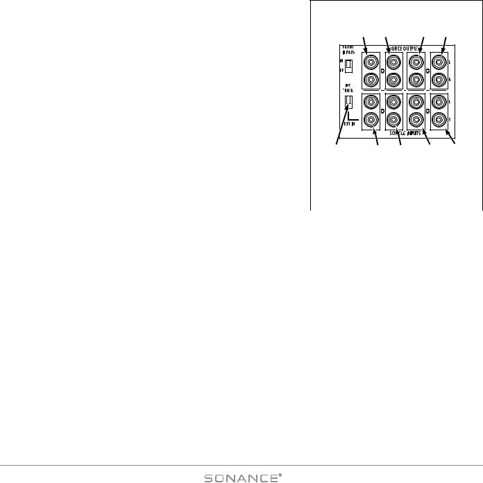
Audio Source Connections |
Source Source Source Source |
|||||
|
||||||
CAUTION: Always unplug the DAB1’s power cord from the wall |
Output Output Output Output |
|||||
outlet before making source signal or speaker connections. |
#1 |
#2 |
#3 |
#4 |
||
The DAB1 has input and output connections for four source components. The |
|
|
|
|
|
|
corresponding SOURCE INPUT and SOURCE OUTPUT connectors are arranged |
|
|
|
|
|
|
vertically (see Figure 6). The SOURCE OUTPUT connections are buffered. |
|
|
|
|
|
|
SO U R C E IN P U T Connections |
|
|
|
|
|
|
Connect a stereo RCA audio cable from the left & right line-level audio |
|
|
|
|
|
|
outputs of a source component to one set of left & right SOURCE INPUT jacks |
|
|
|
|
|
|
on the DAB1. You can connect up to four source components. |
|
|
|
|
|
|
Source 1 I N T T U N E R /E X T I N Switch |
|
|
|
|
|
|
The Source 1 INT TUNER/EXT IN Switch assigns either the DAB1’s internal |
Source #1 |
Source |
Source |
Source Source |
||
FM/AM tuner or the component connected to the #1 SOURCE INPUT jacks as |
INT TUNER/ |
Input |
Input |
Input |
Input |
|
Source 1. |
EXT IN |
#1 |
#2 |
#3 |
#4 |
|
Switch |
||||||
|
|
|
|
|
||
SO U R C E OU T P U T Connections |
Figure 6: |
|
For Recording: Connect a stereo RCA audio cable from one set of DAB1 L&R |
||
Source Input/Output Connections |
||
SOURCE OUTPUT jacks to the record inputs on the recording device. This allows |
|
|
|
||
the source component connected to the corresponding SOURCE INPUT jacks to be |
|
|
recorded. |
|
When Using Multiple DAB1 Controllers: In a system that incorporates multiple DAB1s, you can feed up to four common sources to any or all of the controllers.
1.Designate one DAB1 as the PRIMARY controller and the others as SECONDARY controllers.
2.Connect the source components to the SOURCE INPUTS on the PRIMARY DAB1 as described above.
3.For each source that you want to feed to the SECONDARY controllers, connect a stereo RCA audio cable from its SOURCE OUTPUT Jacks on the PRIMARY DAB1 to the corresponding set of SOURCE INPUT jacks on the SECONDARY DAB1 (SOURCE 1 OUT to SOURCE 1 IN, etc.). You can repeat this for up to four DAB1 Controllers (24 zones). This will feed audio from up to four common sources to all zones in an expanded system.
Speaker Connections
CAUTION: Always unplug the DAB1’s power cord from the wall outlet before making or changing source or speaker connections.
Use Good Speaker Wire
For the best sound you should never use thin-gauge speaker wire – it will constrict the sound and diminish bass response. We recommend that you use premium Sonance MediaLinQ speaker cable, which also complies with UL fire rating codes. You may also experiment with audiophile brands of speaker cable, but be sure to check local codes governing wire that may be installed within walls or ceilings. Use at least 18 AWG speaker wire for runs up to 50’, at least 16 AWG for runs up to 100’ and at least 14 AWG for runs up to 250’.
12
DAB1 DISTRIBUTED AUDIO SYSTEM
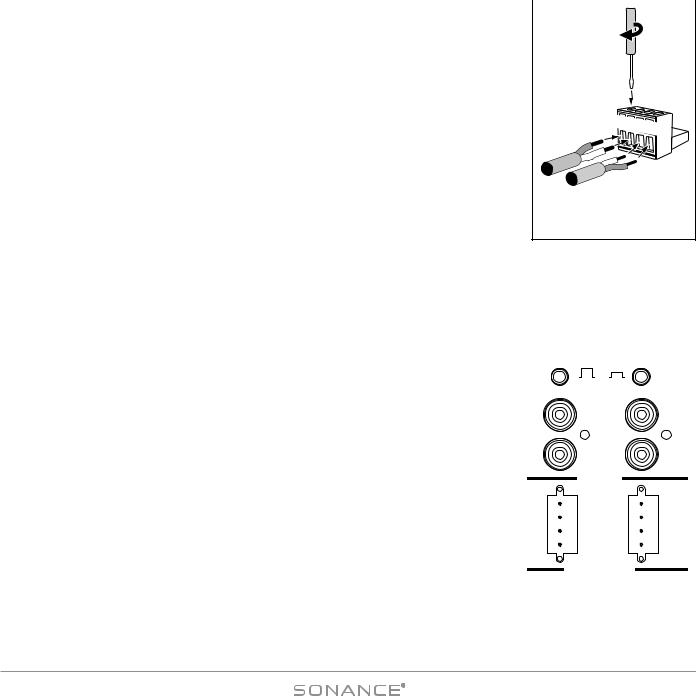
Wiring the Speaker Connectors |
Use |
||
The DAB1’s speaker outputs are rated for 8-ohm nominal speakers. |
|||
|
|
Screwdriver |
|
1. |
Run speaker wire from each speaker to the controller location. We recommend that you |
to Tighten |
|
Set Screws |
|||
|
mark each wire’s positive (‘+’) and negative (‘–’) leads, its channel (left or right) and |
|
|
|
which zone it is from so that you can connect it to the proper speaker terminals. |
|
|
2. |
Strip no more than ¼” of insulation from each speaker lead. Twist the strands or tin the |
|
|
|
exposed wire with solder to ensure that there are no stray strands. (Stray strands that |
L+L–R–R+ |
|
|
touch each other or touch the controller chassis can cause a short-circuit that can dam- |
||
|
|
||
|
age the amplifier.) |
|
|
3. |
The DAB1 has six removable 4-wire speaker connectors (one for each zone) that can |
|
|
|
accept wire up to 14AWG. The connector features set screws that secure the wires. |
Figure 7: |
|
4. |
Insert the exposed portions of the speaker wires into the terminal openings. Make sure |
||
Wiring the Removable |
|||
|
to insert the ‘+’ and ‘–’ leads into the correct openings, as shown in Figure 6. |
||
|
Speaker Connectors |
||
|
|
||
5.After making sure that there are no stray wires touching each other, tighten the set screws to secure the wires, as shown in Figure 7.
6.Press the removable connector into the corresponding zone SPEAKER OUT connector on the controller until it locks into place (see Figure 8).
Zone Line Output Connections
In addition to Speaker Output connectors, each zone on the DAB1 also has a set of Line Output jacks (see Figure 8). |
|||||||||||||||||
The Zone Line Outputs let you connect high-power amplifiers to individual zones that |
|
|
|
|
|
|
|
|
|
|
|
|
|
||||
|
|
|
|
|
|
|
|
|
|
|
|
|
|||||
require more power than the DAB1’s built-in 30 Watt/ch amplifier can provide, or expand |
|
|
|
|
|
OUT |
IN |
|
|
||||||||
a zone into sub-zones by using a multi-channel amplifier. |
|
|
|
|
|
|
VARIABLE |
FIXED |
|||||||||
Line Output Fixed/Variable Switch |
|
|
|
|
|
|
|
|
L |
|
|
|
|
|
L |
||
Each zone Line Output has a push-button switch that toggles the Line Output between |
|
|
|
|
|
|
|
|
|
|
|||||||
|
|
|
|
|
|
|
|
|
|
|
|
|
|||||
VARIABLE (OUT) and FIXED (IN). (See Figure 8.) The VARIABLE setting allows zone keypad |
|
|
|
|
|
|
|
|
|
|
|
|
|
||||
and remote controllers to control the level of the LINE OUTPUTS. In the FIXED setting the LINE |
|
|
|
|
|
R |
|
|
|
|
|
R |
|||||
OUTPUT level cannot be varied. NOT E : T h e k e y p a d a n d re m |
|
|
|
|
|
|
LINE OUT |
||||||||||
c o n t ro l s f u n c t i o n O N LY i n t h e VARIABLE s e t t i n g . |
|
|
|
|
|
|
|||||||||||
|
3 |
4 |
|
||||||||||||||
IMPORTANT: Do not push the Line Output FIXED/VARIABLE switch while the |
|
L+ |
|
|
|
|
L+ |
|
|
|
|
|
|
||||
|
L- |
|
|
|
|
L- |
|
|
|
|
|||||||
DAB1 is operating. Doing so can produce high output levels |
that can |
|
R- |
|
|
|
|
R- |
|
|
|
|
|||||
damage the DAB1, the connected amplifier or the speakers. |
|
|
R+ |
|
|
|
|
R+ |
|
|
|
|
|||||
|
|
|
|
|
SPEAKER OUT |
||||||||||||
Not e : W h e n a z o n e ’ s L i n e O u t p u t i s |
s e t |
t o FIXED, t h e fo l l o w i n g |
S o n a n c e |
|
|
|
|
||||||||||
|
|
|
8 Ω NOMINAL IMPEDANCE |
||||||||||||||
|
|
|
|
|
|
|
|
|
|
|
|
|
|
|
|
||
C o n t ro l M a n a ge r Zone Setup fe a t u re s |
fo r |
t h a t z o n e a re d i s a b l e d fo r t h e |
|
|
|
|
|
Figure 8: |
|
||||||||
L i n e O u t p u t : Default Volume, Maximum Volume, Page Volume, Balance, Bass, |
|
|
|
|
|
|
|||||||||||
|
Zone Line Outputs, Speaker |
||||||||||||||||
Treble. S e e p a ge s 3 2 a n d 3 3 . |
|
|
|
|
Outputs and Line Output |
||||||||||||
|
|
|
|
|
|
Fixed/Variable Switches |
|||||||||||
13

|
|
DAB1 DISTRIBUTED AUDIO SYSTEM |
Figure 9: |
DAB1 |
Virtuoso V834D |
Using a High-Power |
|
|
Amplifier in a Zone |
|
|
|
|
Virtuoso V834D |
|
Sonamp 2120T MkII |
|
Figure 10: |
DAB1 |
|
Using a Multi-Channel Amplifier |
|
Connect |
for Sub-Zone Expansion |
|
|
|
DAB1 CONTROL OUT |
|
|
|
to 875D SE ALL |
|
|
External Trigger |
|
|
TRIGGER MODE |
BUS OUTPUT
INPUT BUFFERED
L |
R |
A
ON HIGH |
ON HIGH ON HIGH ON |
HIGH |
|
|
|
|
|
|
|
|
|
|
|
|
|
|
|
|
|
|
|
|
|
|
|
|
|
|
|
BBE CONTROL |
|
|
|
|
|
|
|
|
|
|
|
|
|
|
|
|
|
|
|
|
|
OFF LOW |
OFF LOW OFF LOW OFF |
LOW |
|
|
|
|
|
|
|
|
|
|
|
|
|
|
|
|
|
|
|
|
|
|
|
|
|
|
|
|
CH1 |
CH2 |
|
|
|
|
CH3 |
|
CH4 |
|
|
CH5 |
CH6 |
|
CH7 |
|
CH8 |
|
|||
|
|
|
|
|
(BRIDGED) |
|
|
|
|
(BRIDGED) |
|
|
|
|
(BRIDGED) |
|
|
|
(BRIDGED) |
|
|
||||
1/2 |
3/4 |
5/6 7/8 |
CH |
DIRECT OFF |
ON |
OFF |
ON |
DIRECT |
DIRECT |
OFF |
ON |
OFF |
ON |
DIRECT |
DIRECT |
OFF |
ON |
OFF |
ON DIRECT |
DIRECT |
OFF |
ON |
OFF |
ON DIRECT |
|
|
|
|
|
|
LEFT OFF |
ON |
OFF |
ON |
LEFT |
LEFT |
OFF |
ON |
OFF |
ON |
LEFT |
LEFT |
OFF |
ON |
OFF |
ON LEFT |
LEFT |
OFF |
ON |
OFF |
ON LEFT |
|
|
|
|
|
RIGHT OFF |
ON |
OFF |
ON |
RIGHT |
RIGHT |
OFF |
ON |
OFF |
ON |
RIGHT |
RIGHT |
OFF |
ON |
OFF |
ON RIGHT |
RIGHT |
OFF |
ON |
OFF |
ON RIGHT |
|
|
|
|
|
AUX OFF |
ON |
OFF |
ON |
AUX |
AUX |
OFF |
ON |
OFF |
ON |
AUX |
AUX |
OFF |
ON |
OFF |
ON AUX |
AUX |
OFF |
ON |
OFF |
ON AUX |
|
|
|
|
|
NORMAL |
BRIDGED |
|
|
NORMAL |
BRIDGED |
|
|
NORMAL |
|
BRIDGED |
|
NORMAL |
|
BRIDGED |
||||||
|
|
|
|
BBE CONTROL |
BRIDGED |
|
|
BRIDGED |
|
|
|
|
|
|
|
|
|
BRIDGED |
|
|
BRIDGED |
||||
|
|
|
|
INPUTS 5 – 24V AC–DC |
8Ω MIN |
|
|
8Ω MIN |
|
|
|
|
|
|
|
|
|
8Ω MIN |
|
|
8Ω MIN |
||||
+ – + – |
+ – |
+ – |
|
|
|
|
|
|
|
|
|
|
|
|
|
|
|
|
|
|
|
|
|
||
|
|
|
|
|
+ 1 – |
– 2 + |
|
|
+ 3 – |
– 4 + |
|
|
|
SONAMP® 875D SE |
|
|
+ 5 – |
– 6 + |
|
|
+ 7 – |
– 8 + |
|||
|
|
|
TRIGGER MODE |
|
|
|
|
|
CH 1/2 |
AUTO |
RS-232 |
|
|
|
VOLT |
RS-232 |
|
|
|
|
CH 3/4 |
AUTO |
|
|
|
|
VOLT |
|
|
ALL 1/2 3/4 |
5/6 |
7/8 CH |
CH 5/6 |
AUTO |
RS-232 |
|
VOLT |
||||
+ – + – + – |
+ – |
+ – |
CH 7/8 |
AUTO |
RS-232 |
|
|
|
VOLT |
||
|
|
|
OFF |
ON |
|
EXTERNAL TRIGGER |
INPUTS 5 – 24V AC–DC |
|
|
|
|
|
TRIGGER OUTPUTS |
250VT10ALFUSE– |
1200W60Hz–120V |
FUSERATINGANDTYPESAME |
THEWITHREPLACECAUTION: |
|
|
|
|
|
12VDC |
|
|
|
|
ALL |
1/2 |
3/4 |
5/6 |
7/8 |
CH |
|
|
|
|
|
|
|
|
|
RS-232 |
|
|
|
|
S/N
CH 1/2 |
AUTO |
RS-232 |
|
VOLT |
|
||
|
RS-232 |
||
CH 3/4 |
AUTO |
||
VOLT |
|
||
|
|
||
CH 5/6 |
AUTO |
|
|
VOLT |
RS-232 |
||
|
|||
CH 7/8 |
AUTO |
|
|
VOLT |
RS-232 |
||
|
OFF ON
Set all 875D SE Trigger Mode VOLT Switches to ON
Sonamp 875D SE
|
Sub-Zone |
Sub-Zone |
Sub-Zone |
Sub-Zone |
Volume |
1 |
2 |
3 |
4 |
Control |
|
|
|
|
14
DAB1 DISTRIBUTED AUDIO SYSTEM
Connecting a High-Power Amplifier in a Zone
1.Set the zone’s Variable/Fixed Output switch to the VARIABLE (OUT) position. Note: If the Zone LINE OUTPUT is set to FIXED, audio will continuously pass to the amplifier inputs, defeating any signal-sensing auto-ON/OFF triggering. In this case, the amplifier should be triggered by a control voltage or other means.
2.Connect a stereo RCA cable from the appropriate Zone Line Outputs on the DAB1 to the high-power amplifier’s input connectors (see Figure 9, opposite). The VARIABLE setting allows the zone’s volume to be controlled by the DAB1 via a keypad or a properly-programmed IR remote.
Using a Multi-Channel Amplifier for Sub-Zone Expansion
1.Set the zone’s Variable/Fixed Output switch to the FIXED (IN) position.
2.Connect a stereo RCA cable from the appropriate Zone Line Outputs on the DAB1 to the multi-channel amplifier’s Bus input connectors (see Figure 10, opposite). For example, an 8-channel amplifier like the Sonamp 875D SE will let you put four speaker pairs in the zone. The VARIABLE output setting allows the DAB1’s Mute function to mute all four sub-zones. Volume for each pair of speakers in each sub-zone is controlled by an in-wall volume control.
3.Connect the Control Out on the DAB1 to the External Control input on the sub-zone amplifier (if available) to automatically power-up the external amp when any zone on the DAB1 is ON.
Not e : T h e DA B 1 c a n a l s o t u r n c o n n e c t e d a m p l i f i e r s O N a n d O F F v i a s e r i a l c o n t ro l . S e e p a ge 4 3 .
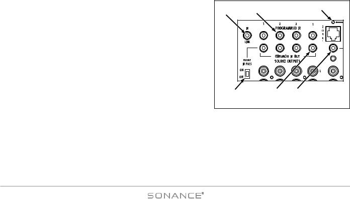
IR Connections (see Figure 11) |
|
|
|
1 |
2 |
3 |
||||
1. IR L I N K Port: |
3.5mm mini jack that creates an IR buss for Common IR |
|||||||||
|
|
|
||||||||
signals when using multiple DAB1s in a system. |
|
|
|
|
|
|||||
• When using two DAB1s, use a 3.5mm mono mini cable to connect |
|
|
|
|||||||
the IR Link jacks on the two units. |
|
|
|
|
|
|
||||
• When using |
three |
or |
more DAB1 Controllers, use |
mini |
plug |
|
|
|
||
Y-adapters on the IR Link jack on the primary DAB1 to connect to |
|
|
|
|||||||
the IR Link jacks of the secondary DAB1s. |
|
|
|
|
|
|||||
2. P R O G R A M M E D |
IR |
O U T |
P o r t s : |
Four 3.5mm mini |
jacks |
that |
|
|
|
|
output IR commands to |
the four |
individual source components as |
4 |
5 |
6 |
|||||
configured in the Sonance Control Manager. (The default |
||||||||||
|
Figure 11: IR Connections |
|||||||||
Programmed |
IR Port settings correspond to the Input Source |
|
||||||||
numbering: Port 1 = Source 1, etc.) Allows IR signals to be routed to |
|
|
|
|||||||
specific source components, for selective control of multiple same-brand, same-model components. |
||||||||||
•Connect one Sonance OptiLinQ®-type IR emitter to each Programmed IR Out port for each source component to be controlled. Attach one emitter to the IR window on each source component.
3 |
. ZO N E |
IR D A T A |
LED: Six amber LEDs (one for each zone) that flash to indicate IR activity in their respective zones. |
4 |
. FR O N T |
IR P A S S |
Switch: Passes IR commands from 3rd-party remotes through the front-panel IR receiver to the |
|
Programmed and/or Common IR Outputs, as configured in the Sonance Control Manager software. |
||
15
DAB1 DISTRIBUTED AUDIO SYSTEM
5. CO M M O N IR O UT Ports: Four 3.5mm mini jacks that output all IR commands regardless of zone for all source components (all zones have control of all sources). Intended for all systems except those that contain multiple same-brand, same-model source components.
•Connect one Sonance OptiLinQ-type IR emitter to each COMMON IR Out port for each common source component to be controlled. Attach one emitter to the IR window on each source component.
6. LO C A L IR O UT Ports: Six 3.5mm mini jacks (one for each zone) that allow control of a specific source component from a specific zone. Connect one Sonance OptiLinQ-type emitter to the appropriate LOCAL IR OUT jack and attach the emitter to the source component’s IR window.
Example: The living room is Zone 1. The CD changer is Source 2 and is to be controlled only from the living room. Connect the IR emitter to the Zone 1 LOCAL IR OUT jack and attach it to the IR window on the CD changer.
The CD changer can be controlled only from the living room, but all zones can still select Source 2 and listen to the CD changer when it is playing.
Control Output, Control Input and Sync Connections (see Figure 12)
CO N T R O L OU T Terminal
One 2-wire screw connector that outputs 12VDC @ 100mA when at least one DAB1 zone is active. Turns OFF (0VDC) when all zones are OFF. Can be used for triggering external devices such as a zone-specific external amplifier. Accepts one pair 14 – 24 AWG wire.
CO N T R O L IN P U T Terminal
A general trigger input that can be used for Paging or sense input as part of a DAB1 STATUS test in a macro. Requires 5 – 24V AC or DC @ 100mA. Accepts one pair 14 – 24AWG wire.
Wiring the CO N T R O L Connections
1. Strip approximately ¼" of insulation from each conductor and twist the strands until tight to prevent stray strands.
CONTROL
+ OUT - |
INPUT |
12 VDC @ |
+6 -24 |
100 mA |
AC/DC |
 SYNC
SYNC
Figure 12:
Control Input/ Output
and Sync Connections
2.Be sure to maintain proper polarity by connecting the appropriate ‘+V’ and ‘GND’ terminals on the device to the appropriate ‘+V’ and ‘GND’ terminals on the DAB1. Be sure the connections are tight and that there are no frayed ends sticking out that could cause a short-circuit.
SY N C Connections
Two 3.5mm mini jacks that are used to trigger-link up to four DAB1s to provide communication between multiple DAB1 units that form large systems with more than 6 zones. For details, see Appendix 1: Party Mode , on page 54. Use mono 3.5mm mini cables to daisy-chain the SYNC jacks of all DAB1 units in the system.
Audio and IR will pass-through multiple DAB1s that are in the Standby mode. Power for the source components should be managed separately or left ON.
If no other zones are ON and a zone on a DAB1 is turned ON with a Source button PRESS, only that DAB1 and that zone will turn ON.
16
DAB1 DISTRIBUTED AUDIO SYSTEM |
|
|
|
|
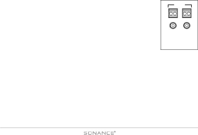
Paging Connections (see Figure 13) |
|
|
|
|
|
|
|
|
|
The DAB1’s Paging connections allow connection of an audio input from a telephone system, |
|
|
|
|
microphone preamp or other device to be distributed to designated Paging zones when triggered |
|
|
|
|
by the CONTROL Input. (Paging must be configured in the Sonance Control Manager.) |
|
IN |
OUT |
|
|
|
|||
When 5 – 24VDC is present at the DAB1 CONTROL IN terminals, all system zones set to ‘Allow |
|
|
PAGE |
|
|
|
|
|
|
Paging’ as configured with the Sonance Control Manager will switch to audio from the PAGE IN |
|
Figure 13: |
||
jack. When the control voltage drops to 0VDC, audio in the zones will switch back to the select- |
P |
aging Connection |
s |
|
ed source component. |
|
|
|
|
|
|
|
|
|
PA G E IN : One gold-plated mono RCA jack. Designed for use with line-level audio input from a telephone system, microphone preamp or other device to be distributed to designated Paging Zones when triggered with the Control Input. (‘Allow Paging’ must be configured in the Sonance Control Manager.)
PA G E OUT : One gold-plated mono RCA jack. Sends the Paging audio signal to other DAB1s in a system using multiple DAB1 controllers.
Trigger Wire: Connect a 2-conductor non-shielded wire from the trigger voltage source on the Paging device to one DAB1’s CONTROL INPUT terminal (see Figure 12, on page 16), and daisy-chain to the CONTROL INPUT terminals of all other DAB1s in the system. (Use 20AWG wire for runs up to 500’; 18AWG wire for runs up to 1000’.)
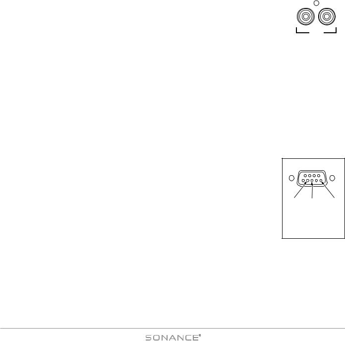
RS-232 Connection (see Figure 14)
The DAB1’s RS-232 connection allows it to send or receive serial commands to or from other components. The RS-232 connection uses a female DB-9 connector with the following pinout configuration:
Pin 2 = Receive ( RX )
Pin 3 = Transmit ( TX )
Pin 5 = Ground ( GND )
Since different serial devices have different RS-232 connection configurations, consult the documentation of the device you want to connect to the DAB1 to determine what cable/adapter may be required.
RS-422 Port (see Figure 3, on page 10)
RS-232
Pin2 |
Pin3 |
Pin5 |
Rx |
Tx |
Gnd |
Figure 14:
RS-232 Terminal Pins
(Connector Side)
The RS-422 port allows the DAB1’s capabilities to be expanded in the future. At the time of this writing (05/07) the RS-422 port was not active. Check www.sonance.com periodically for the latest information about this feature.
17
DAB1 DISTRIBUTED AUDIO SYSTEM
Keypad Controllers
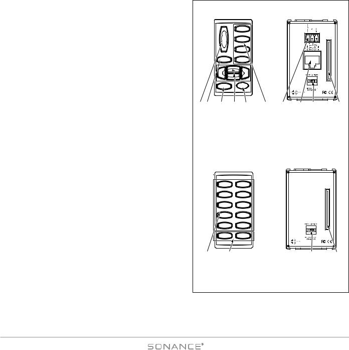
As mentioned previously, the DAB1 can be operated by one or more keypad controller in each zone. The DAB1 can be controlled by the C4630 SE Main and Numeric Keypads (below) and the DAB1 keypad (see page 22). Additionally, the DAB1 can also be controlled by the Sonance Navigator® K1 and K2 keypads (see Using the DAB1 with Sonance Navigator K1 and K2 Programmable Keypads, on page 49).
C4630 SE Main and Numeric Keypad
C4630 SE Main Keypad (see Figure 15)
The C4630 SE Main Keypad lets you control the zone volume, muting and select the active source, as well as providing buttons for controlling the source component that’s active in the zone. A ZONE OFF button is also provided. The ZONE OFF button’s LED color indicates the zone’s status:
Red: |
Zone is OFF (DAB1 is receiving power) |
Green: |
Zone is ON |
Orange: |
Connected IR receiver is receiving IR commands |
(flashing) |
or a keypad button is being pressed. This occurs |
|
even if the Zone is turned OFF. |
Each keypad button has three different actions: PRESS, PRESS-AND- HOLD and DOUBLE-PRESS. This allows each button to issue three distinct commands or macros. Out-of-the-box the following button functions are available on the Main Keypad:
VO L U M E UP/DOWN Buttons: PRESS = Volume UP/DOWN
M U T E b u t t o n : PRESS = Mute/un-Mute the local zone; PRESS-AND-HOLD = Mute/un-Mute all zones designated for PARTY
MODE (see Appendix 1: “Party Mode”, on page 54).
Zone Source Selector Buttons: PRESS = Selects that source in the local zone; PRESS-AND-HOLD = Selects that source in all zones designated for PARTY MODE (see Appendix 1: “Party Mode”, on page 54). Pressing a Source Select button in a zone that is OFF will turn that zone ON.
|
|
Main Keypad |
|
|
Main Keypad |
|
|||
|
|
Front Panel |
|
|
Rear Panel |
|
|||
|
|
|
|
TUNER |
|
|
|
|
|
|
|
|
^ |
|
|
|
|
|
|
|
|
|
VOL |
DVD/CD |
|
|
|
PIN 14 |
|
|
|
|
|
|
|
|
|
||
|
|
|
^ |
|
|
|
|
KEYPAD |
|
|
|
|
|
SAT |
|
|
|
|
|
|
|
MUTE |
TV/AUX |
|
|
C4630 |
NUMBERIC |
|
|
|
|
|
|
MAIN |
|
||||
|
|
|
|
|
|
|
FOR |
|
|
|
|
|
|
|
|
|
KEYPAD |
|
|
|
|
|
^ |
^ |
|
|
|
RESERVED |
|
|
|
|
= |
|
|
|
|
• |
|
|
|
|
|
|
|
|
|
|
|
|
|
|
|
|
|
|
|
PIN 1 |
|
|
|
|
OFF |
|
|
|
1 |
2 |
|
1 |
2 |
3 |
4 |
5 |
6 |
7 |
8 |
9 |
10 |
|
1. Zone Volume UP/DOWN Buttons |
|
7. IR Receiver Connection |
|
|||||
|
2. Zone Mute Button |
|
|
8. RJ45 Connection Jack |
|
||||
|
3. Zone OFF Button |
|
|
9. Keypad Backlight Jumper |
|||||
|
4. Zone Source Control Buttons |
|
|
10. Ribbon Connector for |
|
||||
|
5. Zone IR Receiver Window |
|
|
Numeric Keypad |
|
||||
|
6. Zone Source Selector Buttons |
|
|
|
|
|
|||
|
|
(Source 1 – Source 4) |
|
|
|
|
|
||
|
|
Numeric Keypad |
|
|
Numeric Keypad |
|
|||
|
|
|
|
Rear Panel |
|
||||
|
|
Front Panel |
|
|
|
||||
|
|
|
|
|
|
|
|||
|
|
|
1 |
2 |
|
|
|
PIN 14 |
|
|
|
|
|
|
|
|
|
|
|
|
|
|
3 |
4 |
|
|
|
KEYPAD |
|
|
|
|
|
|
|
|
|
|
|
|
|
|
5 |
6 |
|
|
C4630 |
MAIN |
|
|
|
|
|
|
|
|
NUMERIC |
TO |
|
|
|
|
|
8 |
|
|
KEYPAD |
CONNECTION |
|
|
|
|
7 |
|
|
|
|
||
|
|
|
|
|
|
|
|
|
|
|
|
|
9 |
0 |
|
|
|
• |
|
|
|
|
|
|
|
|
|
|
|
|
|
|
_ |
|
|
|
|
PIN 1 |
|
|
|
|
+ |
|
|
1 |
2 |
|
|
|
|
|
|
|
|
|
|
|
|
|
11 |
|
12 |
|
|
|
13 |
14 |
|
|
|
11. Numeric Buttons |
|
|
13. Keypad Backlight Jumper |
||||
|
|
12. “+” and “–” Buttons |
|
|
14. Ribbon Connector to |
|
|||
|
|
|
|
|
|
|
Main Keypad |
|
|
|
|
|
|
Figure 15: |
|
|
|
||
|
|
C4630 SE Main and Numeric Keypads |
|
||||||
Zone OFF Button: PRESS = Turns the local zone OFF; PRESS-AND-HOLD = Turns all zones OFF (see Appendix 1 on page 54 for information about turning-OFF all zones in systems with multiple DAB1s).
Additional PRESS, PRESS-AND-HOLD, DOUBLE-PRESS, source component control and macro trigger functions require programming
18
DAB1 DISTRIBUTED AUDIO SYSTEM
with the Sonance Control Manager software. The Sonance Control Manager can also be used to change the out-of-the-box button functions.
C4630 SE Numeric Keypad (see Figure 15, opposite)
The C4630 SE Numeric Keypad incorporates ten numeric buttons labeled “0” through “9”, and two buttons labeled “+” and “–”. Like the C4630 SE Main Keypad, each of these buttons has PRESS, PRESS-AND-HOLD and DOUBLE-PRESS functions. Unlike the C4630 SE Main Keypad, the Numeric Keypad has no “out-of-the-box” functions — it must first be programmed with the Sonance Control Manager software. The Numeric Keypad con-
nects to the Main Keypad with the included 14-pin ribbon cable; it can- |
A.Feed Ribbon Cable |
B. Insert Holster |
|
not operate on its own. See Mounting the C4630 SE Keypads, on page |
through Opening |
into Main Keypad |
|
|
|
|
|
20 for details. |
|
|
|
C4630 SE Main Keypad IR Receiver Holster |
|
|
|
The C4630 SE Main Keypad does not feature a built-in IR receiver: it |
|
|
|
has a holster that accepts a Sonance FSMR1 Full-Spectrum IR Receiver |
|
|
IR |
|
|
Photodiode |
|
(part #92222) or MR1 Micro IR Receiver (part #91344), both available |
|
|
|
|
|
|
|
separately. A window on the front of the keypad allows the IR receiver |
FSMR1/MR1 |
IR Receiver |
|
to function (see Figure 15, opposite). IR talkback is through the |
|
||
Holster |
|
||
keypad’s ZONE OFF button. |
IR Receiver |
|
|
|
|
|
|
If the Main Keypad is mounted in a location that creates interference from |
|
|
|
sunlight when the IR receiver is installed in its holster, you can move the |
|
|
IR |
IR receiver to another location in the room and still wire it to the keypad. |
|
|
|
|
|
Window |
|
NOTE: When using C4630 SE keypads, IR receivers must be |
Figure 16: |
|
|
connected to the keypads to allow the included IR remote to control |
|
||
IR Receiver Holster |
|||
the DAB1 from inside the listening zones, and to allow source com- |
|
|
|
ponent remotes to control their respective source components from |
|
|
|
inside the listening zones. |
|
|
|
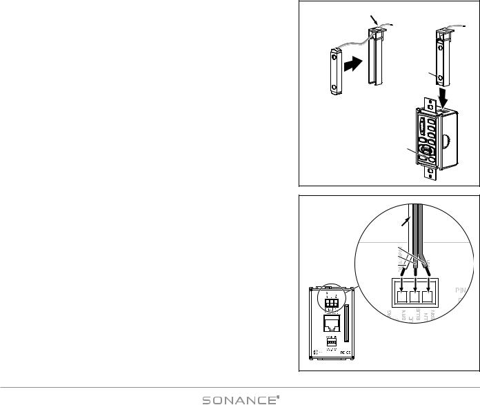
Installing an IR receiver Into a C4630 SE Main Keypad: |
|
|
FROM IR |
|
|
|
RECEIVER |
1. Insert the IR receiver into the keypad holster as shown in Figure 16A. |
|
|
GROUND |
Feed the ribbon cable through the opening in the holster. |
|
|
|
|
|
+12V (center) |
|
|
|
|
|
2. Carefully insert the holster into the keypad as shown in Figure 16B. The IR |
|
|
IR DATA (white) |
receiver’s photodiode should be directly behind the keypad’s IR window. |
|
|
|
3. Connect the IR receiver’s 3-conductor ribbon cable to the keypad’s rear- |
|
|
|
panel IR RECEIVER CONNECTION as shown in Figure 17. The connection |
|
PIN 14 |
|
features a 3-pin removable connector similar to the ones used for the |
|
KEYPAD |
|
speaker connectors. Insert the wires into the openings at the rear of the |
KEYPAD |
NUMBERICFOR |
|
|
C4630 |
|
|
|
MAIN |
|
|
connector and secure them by tightening the screws at the top of the |
|
RESERVED |
|
|
PIN 1 |
Figure 17: |
|
connector. |
|
• |
|
1 |
2 |
Connecting the IR Receiver |
|
• The gray wire on the ribbon cable is the DATA wire, the center wire is |
|
|
|
|
|
to the Keypad |
|
+12V and the remaining wire is GROUND. |
|
|
|
|
|
|
|
|
|
|
19 |
DAB1 DISTRIBUTED AUDIO SYSTEM
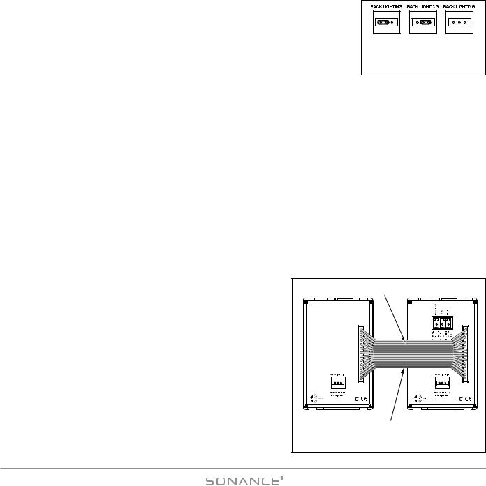
C4630 SE Keypad Backlighting Jumper
The C4630 SE Main and Numeric Keypads have rear-panel Backlight Jumpers (Figure 18) that allow you to adjust the amount of keypad backlighting to suit room lighting conditions and user preference. Position 1 = DIM; Position 2 = BRIGHT; remove the jumper to turn the backlight OFF.
Using needle-nose pliers, tweezers or a similar tool, carefully insert the jumper in the desired position (see Figure 18). The factory default is BRIGHT.
1 |
2 |
1 |
2 |
1 |
2 |
DIM |
BRIGHT |
OFF |
|||
Figure 18: C4630 SE Keypad
Backlight Jumper
NOT E : Un l e s s |
t h e b a c k l i g h t j u m p e r i s re m o v e d , t h e k e y p a d b a c k l i g h t i n g i s a l w ay s O N , e v e n i f t h e |
l o c a l z o n e a n d |
a l l z o n e s a re O F F . |
C4630 SE Keypad Location
The C4630 SE Main and Numeric Keypads can be mounted in standard single or double J-box enclosures or P-rings.
NOT E : D o NOT m o u n t t h e |
C 4 6 3 0 S E k e y p a d s i n t h e s a m e e l e c t r i c a l b o x w i t h AC h o u s e w i r i n g , |
l i g h t s w i t ch e s , o r a ny o t h e r |
h i g h - v o l t a ge d e v i c e o r c o n t ro l . T h e k e y p a d s c a n s h a re ga n g b o x e s w i t h |
each other, or |
with other controls such as A/B speaker switches, infrared receivers and volume controls, |
i f t h e s e o t h e r |
d e v i c e s a re ra t e d a s C l a s s 2 d e v i c e s a c c o rd i n g t o t h e Na t i o n a l E l e c t r i c a l C o d e . |
The C4630 SE keypads should typically be located near the entrance to a room, similar in height and location to a light switch (see NOTE, above). If an optional IR receiver is installed in the Main Keypad (see page 19), care should be taken to avoid placing the keypad near windows or areas that get direct sunlight that could interfere with IR receiver operation. If this is not possible, you should locate the IR receiver away from the keypad.
Avoid mounting keypads in locations that will be exposed to moisture, such as near sinks, showers or bathtubs. If you want to install keypads outdoors, only install them in a covered area with an appropriate weather-proof box.
Mounting the C4630 SE Keypads
1. If you are using both a Main and Numeric |
Keypad, connect |
the |
|
Ribbon Cable |
|
|
||||
Numeric Keypad’s 14-pin ribbon cable between both keypads. |
|
|
|
|
||||||
|
|
|
|
|
||||||
• Connect the ribbon cable so that the wire with |
the red stripe |
|
|
|
|
|||||
connects to Pin 1 on both keypads (see Figure 19). |
|
|
|
PIN 14 |
|
PIN 14 |
||||
|
|
|
|
|
|
|||||
2. Mount the keypad(s) in an appropriate J-box or P-ring as described |
|
CONNECTION TO MAIN KEYPAD |
|
RESERVED FOR NUMBERIC KEYPAD |
||||||
in Keypad Location, above. |
|
|
|
|
C4630 |
C4630 |
||||
• The ribbon |
cable is long |
enough to |
allow |
a Main |
and Numeric |
NUMERIC |
MAIN |
|||
KEYPAD |
KEYPAD |
|||||||||
|
|
|||||||||
Keypad to |
be mounted |
side-by-side |
in a |
double |
J-box. Either |
|
|
|||
|
• |
|
• |
|||||||
keypad can be mounted left or right. |
|
|
|
|
|
|
||||
|
|
|
|
|
PIN 1 |
|
PIN 1 |
|||
NOT E : I f |
t h e r i b b o n |
c a b l e i s c o n n e c t e d i n c o r re c t ly |
t h e |
1 |
2 |
1 |
2 |
|||
|
|
|
|
|||||||
Nu m e r i c K e y p a d ( i n c l u d i n g i t s b a c k l i g h t i n g ) w i l l n o t |
Numeric Keypad |
Main Keypad |
||||||||
f u n c t i o n . |
|
|
|
|
|
|
||||
|
|
|
|
|
|
|
Red Stripe to Pin 1 |
|
||
|
|
|
|
|
|
|
|
|
||
|
|
|
|
|
|
|
Figure 19: Keypad Ribbon Cable |
|||
20 |
|
|
|
|
|
|
|
|
|
|
DAB1 DISTRIBUTED AUDIO SYSTEM
Changing the C4630 SE Main Keypad SO U R C E Buttons
The Source Selector buttons on the C4630 SE Main Keypad are labeled to indicate the specific sources in use on the system. The keypad comes with the following buttons already installed: Tuner, CD/DVD, Sat, TV/Aux. The keypad also comes with a sheet of replacement Source buttons that are labeled for a wide variety of common source components. To change the Main Keypad Source buttons:
1.If the keypad is connected, disconnect it from the DAB1 and from the Numeric Keypad.
2.Use a screwdriver or similar tool to release the keypad bezel tabs (see Figure 20).
3.Remove the keypad bezel and Source buttons from the keypad as shown in Figure 20.
IMPORTANT: Do not touch the exposed portion of the keypad circuit board.
Insert Tool |
Remove Bezel and Source Buttons |
Into Openings |
|
Figure 20: Removing the SOURCE Buttons
from the Main Keypad
4.The four Source buttons are a single unit. Use a razor knife or similar tool to remove the button(s) you want to replace.
5.Use a razor knife or similar tool to separate the desired Source button(s) from the sheet of replacement buttons that’s included with the keypad.
6.Place all 4 of the desired Source buttons into the keypad bezel. The tabs on the buttons will fit-into the depressions adjacent to the openings on the back of the bezel (see Figure 21).
7.Snap the keypad bezel back into place on the keypad.
8.Test all buttons for free movement. If any of the buttons are tight or hang up, carefully remove, realign and replace the bezel.
Tabs
Figure 21:
SOURCE Button Tabs
21
 Loading...