


Lennox LMDV-3530-CNE, LMDV-40, LMDV-4035-CPM, LMDVR-3328-CNM, LMDVT-3328-CNM User Manual
...This appliance may be installed in an aftermarket permanently located, manufactured home (USA only) or mobile home, where not prohibited by local codes. This appliance is only for use with the type of gas indicated on the rating plate. This appliance is not convertible for use with other gases, unless a certified kit is used.
In the Commonwealth of Massachusetts:
•Installation must be performed by a licensed plumber or gas fitter;
•See Table of Contents for location of additional Commonwealth of Massachusetts requirements.
WARNING:IFTHEINFORMATIONINTHISMANUAL IS NOT FOLLOWED EXACTLY, A FIRE OR EXPLOSIONMAYRESULTCAUSINGPROPERTYDAMAGE, PERSONAL INJURY OR LOSS OF LIFE.
Do not store or use gasoline or other flammable vapors or liquids in the vicinity of this or any other appliance.
WHAT TO DO IF YOU SMELL GAS:
•Do not light any appliance.
•Do not touch any electrical switch; do not Use any phone in your building.
•Immediately call your gas supplier from a neighbor’s phone. Follow your gas supplier's instructions.
•If your gas supplier cannot be reached, call the fire department.
Installation and service must be performed by a qualified installer, service agency or the gas supplier.
OTL Report No. 116-F-31-5
US
A French manual is available upon request. Order P/N 850,029CF
Ce manuel d’installation est disponible en francais, simplement en faire la demande. Numéro de la pièce 850,029CF.
INSTALLATION
INSTRUCTIONS
DIRECT VENT MERIT™
LMDV-33/35/40 SERIES
VENTED GAS FIREPLACE HEATERS - DIRECT VENT MODELS
P/N 850,029M REV. G 05/2008
MODELS
Millivolt Models |
Electronic Models |
|
LMDVT-3328-CNM LMDV-3530-CNM |
LMDVT-3328-CNE |
|
LMDVT-3328-CPM |
LMDV-3530-CPM |
LMDVR-3328-CNE |
LMDVR-3328-CNM LMDV-4035-CNM |
LMDV-3530-CNE |
|
LMDVR-3328-CPM |
LMDV-4035-CPM |
LMDV-4035-CNE |
INSTALLER: Leave this manual with the appliance. CONSUMER: Retain this manual for future reference.
AVERTISSEMENT: ASSUREZ-VOUS DE BIEN SUIVRE LES INSTRUCTIONS DONNÉ DANS CETTE NOTICE POUR RÉDUIRE AU MINIMUM LE RISQUE D'INCENDIE OU POUR ÉVITER TOUT DOMMAGE MATÉRIEL, TOUTE BLESSURE OU LA MORT.
POUR VOTRE SÉCURITÉ: Ne pas entreposer ni utiliser d'essence ni d'autre vapeurs ou liquides inflammables dans le voisinage de cet appareil ou
de tout autre appareil.
POUR VOTRE SÉCURITÉ: Que faire si vous sentez une odeur de gaz:
•Ne pas tenter d'allumer d'appareil.
•Ne touchez à aucun interrupteur. Ne pas vous servir des téléphones se trouvant dans le batiment où vous vous trouvez.
•Evacuez la piéce, le bâtiment ou la zone.
•Appelez immédiatement votre fournisseur de gaz depuis un voisin. Suivez les instructions du fournisseur.
•Si vous ne pouvez rejoindre le fournisseur de gaz, appelez le service dos incendies.
L'installation et service doit être exécuté par un qualifié installeur, agence de service ou le fournisseur de gaz.

TABLE OF CONTENTS |
|
|
Packaging.......................................... |
Page |
2 |
Introduction....................................... |
Page |
2 |
General Information........................... |
Page |
2 |
New York City Approval..................... |
Page |
3 |
Requirements for the |
|
|
Commonwealth of Massachusetts..Page |
4 |
|
Cold Climate Insulation...................... |
Page |
4 |
Location............................................. |
Page |
4 |
Manufactured Home Requirements... |
Page |
5 |
Vent Termination Clearances ............ |
Page |
5 |
Appliance and Vent Clearances.......... |
Page |
7 |
Detailed Installation Steps................. |
Page |
8 |
Typical Installation Sequence ............ |
Page |
8 |
Step 1. Framing................................. |
Page |
8 |
Step 2. Routing Gas Line................... |
Page |
8 |
Fireplace Specifications..................... |
Page |
9 |
Step 3. Install the Venting System..... |
Page |
11 |
Vertical Termination Systems............ |
Page |
12 |
Vent Section Length Chart................. |
Page |
12 |
Vertical Vent Tables and Figures........ |
Page |
14 |
Horizontal Termination System.......... |
Page |
16 |
Horizontal Vent Tables and Figures.... |
Page |
19 |
Venting Using Flexible Vent Pipe....... |
Page |
22 |
Step 4. Field Wiring......................... |
Page |
23 |
Step 5. Optional Blower Kit Wiring..Page |
23 |
|
Step 6. Connecting Gas Line............ |
Page |
24 |
Step 7. Checking Unit Operation...... |
Page |
25 |
Step 8. Installing Logs .................... |
Page |
26 |
Step 9. Installing Glass Door .......... |
Page |
29 |
Step 10. Burner Adjustments............. |
Page |
29 |
Step 11. Hood Installation................. |
Page |
30 |
Finishing Requirements..................... |
Page |
30 |
Installation Accessories..................... |
Page |
31 |
Gas Conversion Kits................... |
Page 34 |
|
This manual is part of a set of two supporting this product. Refer to manual 875,028M for Care & Operation information.
Please read and understand these instructions before beginning your installation.
The Millivolt appliances have a millivolt gas control valve with piezo ignition system which provides safe, efficient operation. If any optional accessories that will require electrical power are to be installed, the electrical power must be provided at the time of appliance installation.
The Electronic appliances have an electronic intermittent pilot ignition system which provides safe, efficient operation. External electrical power is required to operate these appliances.
PACKAGING
The assembled vented gas fireplace heater is packaged with:
1 - One log set located in firebox area.
2- One envelope containing the literature package which consists of the homeowner's manual, installation instructions, and warranty; envelope is located in the control compartment.
3- One vent restrictor to be applied as shown on Page 11 ; restrictor is taped to the envelope.
4- One hood located behind the top panel.
5- One bag of decorative volcanic stone located in the control compartment.
6- One bag of glowing embers located in the control compartment.
7- One bag of vermiculite located in the control compartment.
Introduction
These vented gas fireplace heaters are sealed combustion, air circulating gas fireplaces designed for residential applications.
Approved Vent Components - These fireplaces are designed, tested and listed for operation and installation with, the following vent components only:
•Secure Vent™ Direct Vent System Components,
•Secure Flex™ Flexible Vent Components manufactured by Security Chimneys International and
•Z-FLEX™ Model GA Venting Systems listed to UL1777 and ULCS635 manufactured by Flexmaster Canada Limited.
These approved vent system components are labeled for identification. DO NOT use any other manufacturer’s vent components with these appliances. Use only the correct size venting (4-1/2" inner & 7-1/2" outer).
These appliances comply with National Safety Standards and are tested and listed by OMNITest Laboratories, Inc. (Report No. 116-F-31-5) to ANSI Z21.88b (in Canada, CSA-2.33b), and CAN/CGA-2.17-M91 in both USA and Canada, as vented gas fireplace heaters.
Both millivolt and electronic versions of these appliances are listed by OMNI-Test Laboratories for installation in bedrooms and Manufactured Homes.
Manufactured Homes -
See Manufactured Home Requirements on
Page 5 for additional information.
 WARNING
Improper installation, adjustment, alteration, service or maintenance can cause injury or property damage. Refer to this manual. For assistance or additional information consult a qualified installer, service agency or the gas supplier.
NOTE: DIAGRAMS & ILLUSTRATIONS ARE NOT TO SCALE.
This appliance is only for use with the type of gas indicated on the rating plate. This appliance is not convertible for use with other gases, unless a certified kit is used.
Cet appareil doit être utilisé uniquement avec les types de gaz indiqués sur la plaque signalétique. Ne pas l'utiliser avec d'autres gaz sauf si un kit de conversion certifié est installé.
Misc. Codes / Standards -
Installation must conform to local codes. In the absence of local codes, installation must comply with the current National Fuel Gas Code, ANSI Z223.1. (In Canada, the current CAN-1 B149 installation code).
The appliance, when installed, must be electrically grounded & wired in accordance with local codes or, in the absence of local codes, with the National Electrical Code, ANSI / NFPA 70-latest edition, or the Canadian Electrical Code, CSA C22.1 - latest edition.
General Information
Note: Installation and repair should be performed by a qualified service person. The appliance should be inspected annually by a qualified professional service technician. More frequent inspections and cleanings may be required due to excessive lint from carpeting, bedding material, etc.
S'assurer que le brùleur et le compartiment des commandes sont propres. Voir les instructions d'installation et d'utilisation qui accompagnent l'appareil.
Provide adequate clearances around air openings and adequate accessibility clearance for service and proper operation. Never obstruct the front openings of the appliance.
These appliances are designed to operate on natural or propane gas only. The use of other fuels or combination of fuels will degrade the performance of this system and may be dangerous.
These fireplaces are designed as supplemental heaters. Therefore, it is advisable to have an alternate heat source when installed in a dwelling.
Millivolt Models - The millivolt appliances are manually controlled and feature a spark igniter (piezo) that allows the appliance's pilot gas to be lit without the use of matches or batteries. This system provides continued service in the event of a power outage.
Millivolt models come standard with a manu- ally-modulated gas valve; flame appearance and heat output can be controlled at the gas valve. The BTU Input for these appliances is shown in Tables 1 & 2.

Input (BTU) Manually-Modulated Gas
Valves (millivolt models)
NATURAL GAS
Models |
Input Rate (BTU / HR) |
|
|
|
|
LMDVT-3328CNM |
17,500 high |
|
LMDVR-3328CNM |
11,700 low |
|
|
|
|
LMDV-3530CNM |
20,000 high |
|
12,800 low |
||
|
||
LMDV-4035CNM |
27,000 high |
|
18,500 low |
||
|
||
Table 1 |
|
Input (BTU) Manually-Modulated Gas
Valves (millivolt models)
PROPANE GAS
Models |
Input Rate (BTU / HR) |
|
LMDVT-3328CPM |
17,500 high |
|
LMDVR-3328CPM |
14,000 low |
|
|
|
|
LMDV-3530CPM |
20,000 high |
|
15,200 low |
||
|
||
LMDV-4035CPM |
27,000 high |
|
21,500 low |
||
|
Table 2
Electronic Models -
Electronic models have a fixed rate gas valve. Input of electronic models is shown in Table 3.
Electronic Models with Fixed Rate Gas Valve
Natural and Propane Gas
Model Series |
Input Rate |
|
|
(BTU / HR) |
|
|
|
|
LMDVT-3328 |
17,500 |
|
LMDVR-3328 |
||
|
||
|
|
|
LMDV-3530 |
20,000 |
|
LMDV-4035 |
27,000 |
|
|
|
Table 3
Gas Pressure - All Models
Tables 4, 5 and 6 show the appliances' gas pressure requirements:
Inlet Gas Supply Pressure
(all models)
Fuel # |
Minimum |
Maximum |
|
|
|
|
|
Natural Gas |
5.0" WC |
10.5" WC |
|
(1.24 kPa) |
(2.61 kPa) |
||
|
|||
|
|
|
|
Propane |
11.0" WC |
13.0" WC |
|
(2.74 kPa) |
(3.23 kPa) |
||
|
Table 4
Manifold Gas Supply Pressure
(millivolt models)
Fuel # |
Low |
High |
|
|
|
|
|
Natural |
(Lo) 2.2" WC |
(Hi) 3.5" WC |
|
Gas |
(.55 kPa) |
(.87 kPa) |
|
|
|
|
|
Propane |
(Lo) 6.3" WC |
(Hi) 10.0" WC |
|
(1.57 kPa) |
(2.49 kPa) |
||
|
|||
|
|
|
Table 5
Manifold Gas Supply Pressure
(electronic models)
Fuel # |
Maximum Manifold Pressure |
Natural Gas |
(Hi) 3.5" WC (.87 kPa) |
|
|
Propane |
(Hi) 10.0" WC (2.49 kPa) |
|
|
Table 6
Test gauge connections are provided on the front of the millivolt gas control valve, identified IN for the inlet and OUT for the manifold side. A 1/8" NPT Test gauge connection is provided at the inlet and outlet side of the electronic gas control valve.
These appliances must be isolated from the gas supply piping system (by closing their individual manual shut-off valve) during any pressure testing of the gas supply piping system at test pressures equal to or less than 1/2 psig (3.5 kPa).
These appliances and their individual shut-off valves must be disconnected from the gas supply piping system during any pressure testing of that system at pressures greater than 1/2 psig (3.5 kPa).
Orifice Sizes - Sea Level to High Altitude
(All Models)
These appliances are tested and approved for installation at elevations of 0-4500 feet (0-1372 meters)abovesealevelusingthestandardburner orifice sizes (marked with an "*" in Table 7). For elevations above 4500 feet, contact your gas supplier or qualified service technician .
Burner Orifice Sizes Elevation 0-4500 feet ( 0-1372 meters)
Model |
Nat.Gas |
Propane |
|
Series |
drill size (inches) |
drill size (inches) |
|
|
|
|
|
LMDVT-3328 |
#45 (.082") * |
(.048") * |
|
LMDVR-3328 |
39L66 • |
99K780 • |
|
LMDV-3530 |
#44 (.086") * |
#55 (.052") * |
|
60J8001 • |
19L5201 • |
||
|
|||
|
|
|
|
LMDV-4035 |
#37 (.104") * |
1/16" (.062")* |
|
24M1001 • |
21L0101 • |
Table 7 |
* Standard size installed at factory |
|
• Part /Cat. Number |
||
|
NOTE: DIAGRAMS & ILLUSTRATIONS ARE NOT TO SCALE.
Install the appliance according to the regulations of the local authorities having jurisdiction and, in the USA, the National Fuel Gas Code NFPA 54 / ANSI Z223.1 - latest edition or, in Canada, the CAN1-B149.1 and .2 codes - latest edition.
Gas Valve Diagrams
See Figures 1 & 2 for Millivolt models and Figure 3 For Electronic Models.
SIT Millivolt |
Gas Valve |
|||
HI/LO Variable |
|
|
Inlet Pressure Tap |
|
Flame Height |
|
|
||
|
|
|
|
|
Adjustment |
Manifold Pressure Tap |
|||
|
||||
HTPT |
|
|
OUT |
IN |
|
|
|
|
|
PT |
|
IH |
OFF |
|
|
|
|
P |
|
|
|
|
|
|
|
|
|
|
I |
|
|
LOW |
it |
L |
HT |
|
O |
||
|
|
|
|
T |
|
|
|
NO |
|
P |
|
|
|
|
I |
|
|
|
|
TOL |
|
|
|
|
Pilot Adjustment |
Main Gas |
|
||
Screw |
|
Control Knob |
|
|
|
|
OFF/PILOT/ON |
|
|
Figure 1 |
|
|
|
|
Honeywell Millivolt |
Gas Valve |
|||
|
|
PIEZO |
|
|
PILOT |
|
IGNITER |
CONVERTIBLE |
|
|
|
|||
|
|
HI/LO REGULATOR |
||
ADJUSTMENT |
GAS CONTROL |
|||
(adjusts flame height |
||||
SCREW |
||||
KNOB |
|
and heat output) |
||
|
|
|||
TP/TH |
|
O |
|
|
|
|
NI |
|
|
|
|
|
L |
|
|
|
P |
O |
|
TP |
|
H |
||
L |
I |
|
||
|
FFO TO |
|
|
|
TH |
|
|
|
|
WIRING |
INLET |
OUTLET |
||
TERM- |
PRESSURE |
PRESSURE |
||
INALS |
TAP |
TAP |
||
Figure 2 |
|
|
|
|
Honeywell Electronic Gas Valve
Manifold Pressure |
ON / OFF Switch |
||
Port |
|
|
Inlet |
|
|
|
|
C |
|
|
Pressure |
LORTNO |
FFO NO |
N |
Port |
|
|
I |
|
ERTINGI |
|
|
Electronic |
|
|
|
|
|
|
ISP |
Gas |
|
|
|
Control |
|
|
|
Valve |
Figure 3
Massachusetts And New York City, NY Requirements
These appliances are approved for installation in the following USA locations listed in the following:
Massachusetts:
These fireplaces are approved for installation in the US state of Massachusetts if the following additional requirements are met-
•Installation and repair must be done by a plumber or gas fitter licensed in the Commonwealth of Massachusetts.
•The flexible gas line connector used shall not exceed 36 inches (92 centimeters) in length.
•The individual manual shut-off must be a T-handle type valve.
Massachusetts Horizontal Vent Requirements
In the Commonwealth of Massachusetts, horizontal terminations installed less than seven
(7) feet above the finished grade must comply with the following additional requirements:
•A hard wired carbon monoxide detector with an alarm and battery back-up must be installed on the floor level where the gas fireplace is installed. The carbon monoxide detector must comply with NFPA 720, be ANSI/UL 2034 listed and be ISA certified.
•A metal or plastic identification plate must be permanently mounted to the exterior of the building at a minimum height of eight (8) feet above grade and be directly in line with the horizontal termination. The sign must read, in print size no less than one-half (1/2) inch in size, GAS VENT DIRECTLY BELOW. KEEP CLEAR OF ALL OBSTRUCTIONS.
New York City, NY:
These fireplaces are approved for installation in New York City in the US state of New York.
Cold Climate Insulation
For cold climate installations, seal all cracks around the appliance with noncombustible material and wherever cold air could enter the room. It is especially important to insulate outside chase cavity between studs and under floor on which the appliance rests, if floor is above ground level. Gas line holes and other openings should be caulked or stuffed with unfaced fiberglass insulation. If the fireplace is being installed on a cement slab, in cold climates, a sheet of plywood or other raised platform can be placed underneath to prevent conducting cold up into the room. It also helps to sheetrock inside surfaces and tape for maximum air tightness and caulk firestops.
|
|
|
|
|
|
|
|
REAR VENT APPLICATION |
|
R |
|
|
|
|
|
|
|
|
|
|
|
|
A E |
|
|
|
|
|
|
|
|
|
T |
|
|
P A |
|
|
|||
|
|
|
|
|
N |
|
P R |
|
|
||||
|
|
|
|
N |
|
|
L |
V |
|
||||
|
|
|
E |
|
IO |
|
I |
|
|||||
|
|
|
|
|
C |
E |
|||||||
|
|
V |
|
|
T |
|
|
||||||
|
P |
|
|
|
|
|
A |
N |
|||||
|
|
|
A |
|
|
T |
|
T |
|||||
O |
|
C |
|
|
|
|
I |
|
|
||||
I |
|
|
|
|
|
O |
|
||||||
T |
|
|
L |
|
|
|
|
|
N |
||||
|
|
P |
|
|
|
|
|
|
|
|
|
||
|
P |
|
|
|
|
|
|
|
|
|
|
||
A |
|
|
|
|
|
|
|
|
|
APPLICATION |
|
||
APPLICATION |
TOP VENT |
APPLICATION |
TOP VENT |
|
|||||||||
TOP VENT |
|
||||||||||||
|
|
|
APPLICATION |
|
|||||||||
|
|
|
|
|
|
RECESSED |
|
TOP VENT |
|
||||
|
|
|
|
INSTALLATION |
|
|
|||||||
|
|
|
|
|
|
|
|
|
TOP VENT |
|
|
|
|
|
|
|
|
|
|
|
|
|
APPLICATION |
|
|
|
|
|
|
|
|
|
|
|
|
|
|
|
|
|
|
|
|
|
|
|
|
|
|
|
|
|
|
|
|
|
|
|
|
|
|
|
|
|
|
|
|
|
|
|
|
|
|
|
|
|
|
|
|
|
|
|
|
|
|
|
|
|
|
|
|
|
|
|
|
|
|
|
|
|
|
|
|
HORIZONTAL VENT |
|
|
|||||
VERTICAL VENT |
|
|
|||||||||
|
|
||||||||||
(Rear Vent |
(Rear Vent Application |
|
|
||||||||
Application) |
without a chase) |
|
|
||||||||
|
|
|
|
|
|
|
|
|
|
|
|
|
|
|
|
|
|
|
|
|
|
|
|
|
|
|
|
|
|
|
|
|
|
|
|
|
|
|
|
|
|
|
|
|
|
|
|
HORIZONTAL VENT (Rear Vent Application With a chase)
|
|
|
VERTICAL VENT |
HORIZONTAL VENT |
|||
(Top Vent |
(Top Vent |
||
Application) |
Application) |
||
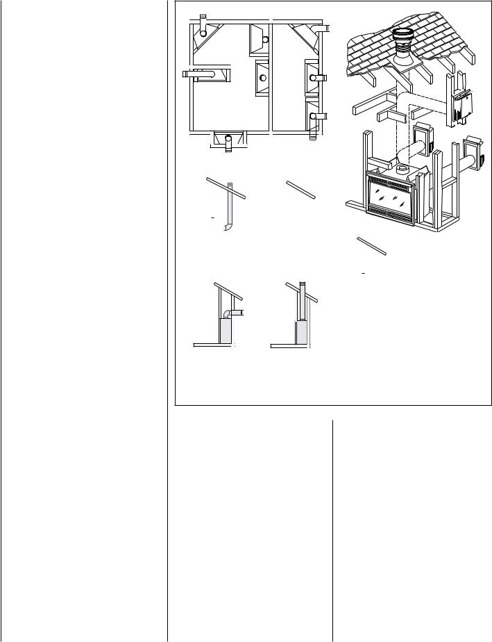
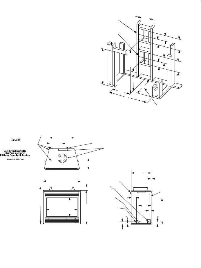
Figure 4 - Typical Locations
Location
In selecting the location, the aesthetic and functional use of the appliance are primary concerns. However, vent system routing to the exterior and access to the fuel supply are also important. Consideration should be given to traffic ways, furniture, draperies, etc., due to elevated surface temperatures (Figure 4). The location should also be free of electrical, plumbing or other heating/air conditioning ducting.
These direct vent appliances are uniquely suited for installations requiring a utility shelf positioned directly above the fireplace. Utility shelves like these are commonly used for locating television sets and decorative plants. Be aware that this is a heat producing appliance. Objects placed above the unit are exposed to elevated temperatures.
To provide for the lowest possible shelf surface use the alternate rear vent outlet with attached venting routed in a way to minimize obstructions to the use of the space above the appliance. Do not insulate the space between the appliance and the area above it. See Figure 9. The minimum height from the base of the appliance to the underside of combustible materials used to construct a utility shelf in this fashion is shown in the Table in Figure 9.
The appliance should be mounted on a fully supported base extending the full width and depth of the unit. The appliance may be located on or near conventional construction materials. However, if installed on combustible materials, such as carpeting, vinyl tile, etc., a metal or wood barrier covering the entire bottom surface must be used.
NOTE: DIAGRAMS & ILLUSTRATIONS ARE NOT TO SCALE.
MANUFACTURED HOME
REQUIREMENTS
This appliance may be installed in an aftermarket permanently located, manufactured home (USA only) or mobile home, where not prohibited by local codes.
Cet appareil peut être installé dans un maison préfabriquée (É.-U. seulement) ou mobile déjà installée à demeure si les réglements locaux le permettent.
Manufactured Home installations must be installed in accordance with these instructions and the following standards / codes:
•Manufactured Home Construction and Safety Standard Title 24 CFR, Part 3280, or the current Standard for Fire Safety Criteria for Manufactured Home Installations, Sites and Communities ANSI / NFPA 501A in the USA, and CAN / CSA Z240 MH Mobile Home Standard in Canada
•(when applicable) The American National Standardfor Manufactured Homes (NCSBCS / ANSI A225.1 - latest edition).
 CAUTIONS
Ensure that the cross members are not cut or weakened during installation. The structural integrity of the manufactured home floor, wall, and ceiling / roof must be maintained.
Thisappliancemustbe grounded to the chassis of the manufactured home in accordance with local codes or in the absence of local codes, with the National Electrical Code ANSI / NFPA 70 - latest edition or the Canadian ElectricalCodeCSAC22.1-latest edition.
Vent Termination Clearances
These instructions should be used as a guideline and do not supersede local codes in any way. Install vent according to local codes, these instructions, the current National Fuel Gas Code (ANSI-Z223.1) in the USA or the current standards of CAN/CGA-B149.1 and -B149.2 in Canada.
Terminate multiple vent terminations according to the installation codes listed above.
Terminate single vent caps relative to building components according to Figure 5.
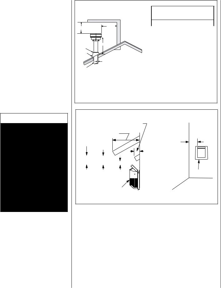
Vertical Vent Termination Clearances
TERMINATION HEIGHTS FOR VENTS ABOVE FLAT OR SLOPED ROOFS
Horizontal Overhang
2 FT MIN.
Vent
Termination
Storm Collar
Flashing
Concentric
Vent Pipe
2 FT |
|
Vertical |
MIN. |
|
Wall |
|
|
Lowest
Discharge
 Opening
H*
X
12
Roof Pitch is X/12
1 inch (25.4 mm) Minimum Clearance to Combustibles
*H = MINIMUM HEIGHT FROM ROOF TO LOWEST DISCHARGE OPENING OF VENT
The vent / air intake termination clearances above the high side of an angled roof is as shown in the following chart:
Figure 5
Termination Heights For Vents Above Flat Or Sloped Roofs Ref. NFPA 54 / ANSI Z223.1, 7.6
Roof Pitch |
* Feet |
*Meters |
|
|
|
Flat to 6/12 |
1.0 |
0.3 |
|
|
|
6/12 to 7/12 |
1.25 |
0.38 |
|
|
|
7/12 to 8/12 |
1.5 |
0.46 |
|
|
|
8/12 to 9/12 |
2.0 |
0.61 |
9/12 to 10/12 |
2.5 |
0.76 |
|
|
|
10/12 to 11/12 |
3.25 |
0.99 |
|
|
|
11/12 to 12/12 |
4.0 |
1.22 |
12/12 to 14/12 |
5.0 |
1.52 |
|
|
|
14/12 to 16/12 |
6.0 |
1.83 |
16/12 to 18/12 |
7.0 |
2.13 |
|
|
|
18/12 to 20/12 |
7.5 |
2.29 |
20/12 to 21/12 |
8.0 |
2.44 |
|
|
|
Horizontal Vent Termination Clearances
Combustible Projection 2-1/2 inches or less in length
Combustible Projection greater than 2-1/2 inches in length
Ventilated
Soffit Unventilated
Soffit
|
|
|
|
|
|
|
3" |
|
18" |
12" |
|
|
|||||
|
|
(76 mm) |
||||||
|
|
|||||||
(457 mm) |
(305 mm) |
|
|
|
|
|||
|
|
|
|
|||||
|
|
|
|
|
|
|
|
|
Side Elevation View
Termination Kit
All horizontal terminations |
|
may be located as close as |
|
6” (152mm) to any |
|
(non-combustible and |
|
combustible) exterior |
|
sidewall. This distance |
|
may be decreased to 2” |
|
(51mm) for non- |
|
combustible exterior |
|
sidewalls only, if the |
|
SV4.5HT-2 termination |
|
is used. |
Termination Kit |
|
Figure 6 |
Note - See Figure 35 on Page 20 for the exterior wall recess |
allowances of the square horizontal termination. |
Horizontal Vent Termination Clearances
The horizontal vent termination must have a minimum of 3" (76 mm) clearance to any overhead combustible projection of 2 1/2" (64 mm) or less. See Figure 6. For projections exceeding 2 1/2" (64 mm), see Figure 6. For additional vent location restrictions refer to Figure 7 on Page 8.
NOTE: DIAGRAMS & ILLUSTRATIONS ARE NOT TO SCALE.
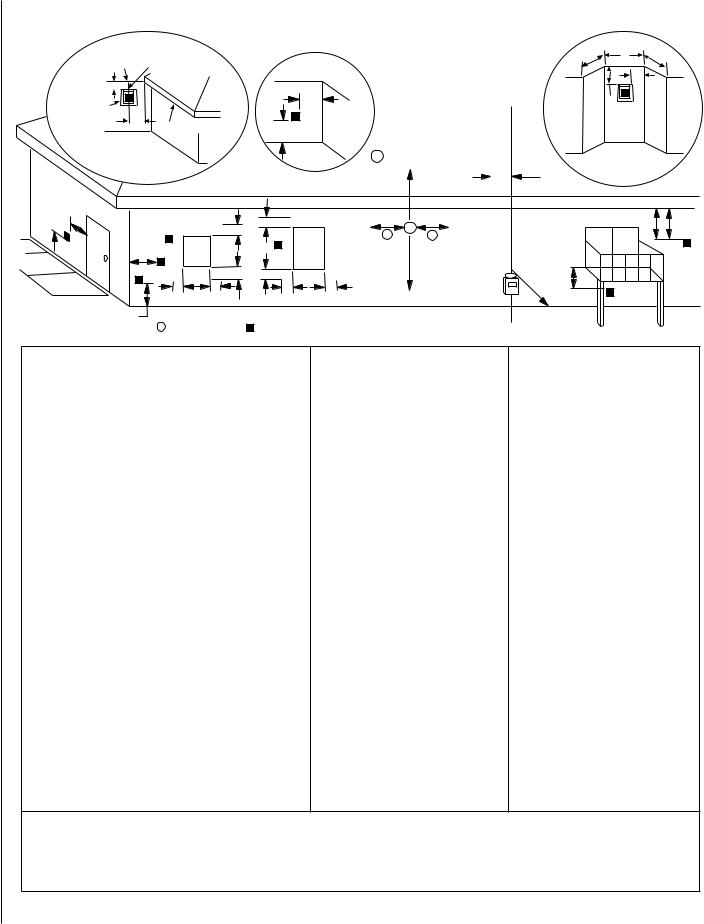
Exterior HORIZONTAL Vent TERMINATION Clearance Requirements
V  L
L
|
|
|
|
|
|
|
|
|
|
NOTE: Local Codes Or Regulations |
|
|
|
|
|
* See Item D in the Text Below. |
|
|
|
|
|
May Require Different Clearances. |
|
|
P |
|
|||||
|
|
|
|
|
NOTE: Location Of The Vent Termination |
N |
|
N |
|||||||
Exterior Wall |
Center Line |
|
|
Inside |
|
|
|
||||||||
|
|
|
|
|
|
|
|
||||||||
|
|
of Termination |
|
|
Corner Detail |
|
Must Not Interfere With Access To The |
|
|
|
O |
||||
*18” |
|
|
|
|
|
|
|
Electrical Service. |
|
|
|
||||
|
|
|
|
|
|
|
|
|
|
|
|
|
V |
|
|
Horizontal |
V |
|
|
|
|
|
G |
|
|
|
|
|
Q |
|
|
|
|
|
|
|
|
|
|
|
|
|
|
||||
Termination |
|
|
|
|
|
|
V |
|
|
|
|
|
|
|
|
|
18” |
Ventilated Soffit |
|
|
|
|
|
|
|
|
|
|
|||
|
|
|
|
|
|
|
|
|
|
|
|
||||
|
|
|
A |
|
|
|
|
|
|
|
|
||||
|
|
|
|
|
|
|
|
|
|
|
|
|
|
||
Inside Corner |
|
|
|
|
|
|
= 9” in U.S. |
|
|
|
|
||||
|
|
|
|
|
|
|
|
A |
|
|
|
|
|||
|
Detail D |
|
|
|
|
|
= 12” in Canada |
|
|
|
|
||||
|
|
|
|
|
|
|
|
|
|
|
|
H |
|
|
|
|
|
|
|
|
|
|
|
|
|
3 ft. |
|
|
|
|
|
B |
|
|
|
|
C |
B |
|
|
|
X |
|
|
|
|
D |
|
|
|
V |
|
|
|
|
A |
A |
|
|
|
|
||
|
|
|
|
|
|
|
|
|
|
|
|
V |
|||
|
|
|
Fixed |
|
V |
Operable |
|
|
|
|
|
|
|
||
|
|
|
|
|
|
|
|
|
|
|
|
||||
|
|
|
|
Closed |
|
|
Window |
|
|
3 ft. |
|
|
|
|
|
|
F |
V |
|
Window |
|
|
|
|
|
|
|
|
|
|
|
|
|
|
|
|
|
|
|
|
|
|
|
|
|
||
|
|
|
|
C |
B |
|
|
J |
|
|
M |
|
|
|
|
|
V |
|
|
|
|
|
|
|
|
|
|
||||
|
|
|
C |
C |
|
B |
B |
|
|
|
|
|
|
||
|
|
|
|
|
|
|
|
|
V |
|
|
||||
|
|
|
|
|
|
|
|
|
|
|
|
|
|
|
|
|
A |
|
|
|
|
|
|
|
|
|
|
I |
|
|
|
|
|
|
|
|
|
|
|
|
|
|
|
|
|
|
|
|
|
X = Air Supply Inlet |
V = Vent Terminal |
= Area where Terminal is not Permitted |
|
|
|
|
|||||||
|
Canadian Installation* |
US Installation** |
|
|
|
A = Clearance above grade, veranda, porch, deck, or balcony. |
12 inches (30cm)* |
12 inches (30cm)** |
B = Clearance to window or door that may be opened. |
6 inches (15cm) for appliances |
6 inches (15cm) for appliances |
|
< 10,000 Btuh (3kW), 12 inches (30cm) |
< 10,000 Btuh (3kW), 9 inches (23cm) |
|
for appliances > 10,000 Btuh (3kW) |
for appliances > 10,000 Btuh (3kW) and |
|
|
< 50,000 Btuh (15kW), 12 inches (30cm) |
|
|
for appliances > 50,000 Btuh (15kW)** |
|
|
|
C = Clearance to permanently closed window |
12 inches (305mm) recommended to |
9 inches (229mm) recommended to |
|
prevent window condensation |
prevent window condensation |
D = Vertical clearance to ventilated soffit located above the |
18 inches (458mm) |
18 inches (458mm) |
terminal within a horizontal distance of 18 inches (458mm) |
|
|
from the center line of the terminal |
|
|
E = Clearance to unventilated soffit*** |
12 inches (305mm) |
12 inches (305mm) |
F = Clearance to outside corner |
5 inches (12.7cm) minimum |
5 inches (12.7cm) minimum |
G = Clearance to inside corner |
6 inches (15.2cm) minimum |
6 inches (15.2cm) minimum |
|
|
|
H = Clearance to each inside of center line extended above |
3 feet (91cm) within a height of 15 feet |
3 feet (91cm) within a height of 15 feet |
meter/regulator assembly |
above the meter/regulator assembly* |
above the meter/regulator assembly** |
I = Clearance to service regulator vent outlet |
3 feet (91cm)* |
3 feet (91cm)** |
|
|
|
J = Clearance to nonmechanical air supply inlet to building or |
6 inches (15cm) for appliances |
6 inches (15cm) for appliances |
the combustion air inlet to any other appliance |
< 10,000 Btuh (3kW), 12 inches (30cm) |
< 10,000 Btuh (3kW), 9 inches (23cm) |
|
for appliances > 10,000 Btuh (3kW) |
for appliances > 10,000 Btuh (3kW) and |
|
|
< 50,000 Btuh (15kW), 12 inches (30cm) |
|
|
for appliances > 50,000 Btuh (15kW)** |
K = Clearance to a mechanical air supply inlet |
6 feet (1.83m)* |
3 feet (91cm) above if within 10 feet |
|
|
(3m) horizontally** |
L = Clearance above paved sidewalk or paved diveway located |
7 feet (2.13m)‡ |
7 feet (2.13m)‡ |
on public property |
|
|
M = Clearance under veranda, porch, deck or balcony |
12 inches (30cm)*‡ |
12 inches (30cm)‡ |
|
|
|
N = Depth of Alcove (Maximum) |
6 feet (1.83m)* |
6 feet (1.83m)** |
O = Clearance to Termination (Alcove) |
6 inches (15.2mm)* |
6 inches (15.2mm)** |
P = Width of Alcove (Minimum) |
3 feet (91cm)* |
3 feet (91cm)* |
Q = Clearance to Combustible Above (Alcove) |
18 inches (457mm)* |
18 inches (457mm)** |
* In accordance with the current CSA-B149.1 National Gas And Propane Installation Code. ** In accordance with the curent ANSI SZ223.1/NFPA 54 National Fuel Gas Codes.
*** Clearance required to vinyl soffit material - 30 inches (76cm) minimum.
‡ A vent shall not terminate directly above a sidewalk or paved driveway which is located between two single family dwellings and serves both dwellings.
*‡ Only permitted if veranda, porch, deck or balcony is fully open on a minimum 2 sides beneath the floor:
Figure 7
NOTE: DIAGRAMS & ILLUSTRATIONS ARE NOT TO SCALE.
Minimum Clearances to Combustibles
Hearth Extension A hearth extension is not required with this appliance. If a hearth extension is |
Appliance and Vent Clearances |
||||||||||||
used, do not block the lower control compartment door. Any hearth extension used is for appearance |
The appliance is approved with zero clearance to |
||||||||||||
only and does not have to conform to standard hearth extension installation requirements. |
combustible materials on all sides (as detailed in |
||||||||||||
|
|
|
|
|
|
|
|
|
|
||||
Wall Finishes / Surrounds / Mantels |
|
|
|
|
|
|
Table 8), with the following exception: When the |
||||||
Note: Combustible wall finish materials and/or surround materials must not be allowed to encroach |
unit is installed with one side flush with a wall, the |
||||||||||||
the area defined by the appliance front face (black sheet metal). Never allow combustible materials |
wall on the other side of the unit must not extend |
||||||||||||
to be positioned in front of or overlapping the appliance front face. See Figure 61 on Page 30. |
beyondthefrontedgeoftheunit.Inaddition,when |
||||||||||||
Non-combustible materials, such as surrounds and other appliance trim, may be installed on the |
the unit is recessed, the side walls surrounding |
||||||||||||
the unit must not extend beyond the front edge |
|||||||||||||
appliance front face with these exceptions: they must not cover any portion of the removable glass |
|||||||||||||
of the unit. See Figure 4. |
|||||||||||||
panel or louvers. |
|
|
|
|
|
|
|
|
|
||||
Vertical installation clearances to combustible mantels vary according to the depth of the mantel. |
|
|
|||||||||||
MINIMUM CLEARANCES Inches (millimeters) |
|||||||||||||
See Figure 8. Mantels constructed of non-combustible materials may be installed at any height |
|
|
|
||||||||||
Back |
|
1/2 (13) |
|||||||||||
above the appliance opening; however, do not allow anything to hang below the hood. |
|
||||||||||||
|
|
|
|
|
|
|
|
|
|
|
|
0 (0) Spacers |
|
|
|
|
|
|
|
|
|
|
|
Sides |
|
1/2 (13) |
|
|
|
|
|
|
|
|
|
|
|
|
|||
|
|
Mantel Depth |
|
|
|
inches (millimeters) |
|
|
0 (0) Spacers |
||||
|
|
|
|
|
|
|
|||||||
|
|
|
|
||||||||||
14 (356) |
|
|
|
|
|
|
|
|
|
Top Spacers |
|
0 (0) |
|
|
|
|
|
|
|
|
|
|
|
|
|
|
|
12 (305) |
|
|
|
|
|
|
|
|
|
Floor |
|
0 (0) |
|
|
|
|
|
|
|
|
|
|
|
|
|
||
10 (254) |
|
|
|
|
|
|
|
|
|
Bottom of Appliance |
|
64 (1626) |
|
|
|
|
|
|
|
|
|
|
To Ceiling |
|
|||
|
|
|
|
|
|
|
|
|
|
||||
|
|
|
|
|
|
|
|
|
|
|
|
||
8 (203) |
|
|
|
|
|
|
|
|
|
|
|
|
|
|
|
|
|
|
Top of |
Vent |
|
3 (76) Top * |
|||||
|
|
|
|
|
|
|
|||||||
|
|
|
|
|
|
|
|
1 (25.4) Sides & Bottom |
|||||
6 (152) |
|
|
|
|
|
Appliance |
|
|
|||||
4 (102) |
|
|
|
|
|
|
|
|
|
SERVICE CLEARANCES Feet (meters) |
|||
|
|
|
|
|
|
|
|
|
|
|
|
||
|
|
|
|
|
|
|
|
|
|
Front |
|
3 ft. (0.9 m) |
|
|
|
|
|
|
|
|
|
|
|
|
|
|
|
12 |
10 |
8 |
6 |
4 |
2 |
|
|
|
|
Table 8 |
|
||
(305) |
(254) |
(203) |
(152) |
(102) |
(51) |
|
|
|
|
|
|
|
|
|
|
|
|
*Note: 3 in. (75 mm) above any horizontal/in- |
|||||||||
|
|
|
|
|
|
|
|
|
|
||||
|
|
|
|
|
|
|
|
|
|
clined vent component. |
|
||
Note - Hood shown as positioned with louvered panels.
**Note: See Page 8, Step 1 for clearance Figure 8 - Minimum Mantel Clearances requirements to the nailing flange located at each side of the unit and any screw heads
adjacent to it.
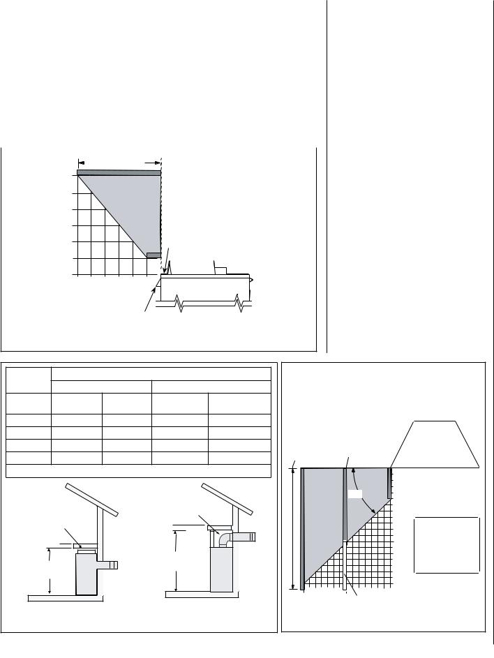
Model No. |
Combustible Shelf Height - Inches (millimeters) |
Minimum Distance to Unprotected Side Wall |
||||||
Top Vent - with One 90 Degree Elbow |
Rear Vent - Straight Out the Back |
Combustible materials may project beyond the sides of the fire- |
||||||
|
||||||||
|
|
|
|
|
||||
|
Secure Vent |
Secure Flex |
Secure Vent |
Secure Flex |
place opening as long as they are kept within the shaded areas |
|||
|
|
(flex elbow) |
|
|
illustrated here. |
|
|
|
LMDVT-3328 |
*44-1/2 (1130) |
*46-1/4 (1175) |
N/A |
N/A |
At 14" minimum |
|
|
|
|
|
|
|
|
|
|
||
LMDVR-3328 |
N/A |
N/A |
33-1/4 (845) |
33-1/4 (845) |
side wall clearance, At 8-1/4" side |
|
||
|
|
|
|
|
a combustible wall |
wall clearance, a |
Top View of |
|
LMDV-3530 |
*46-1/2 (1181) |
*48-1/4 (1226) |
35-1/4 (895) |
35-1/4 (895) |
can project to any |
combustible wall |
Fireplace |
|
can project 12" |
||||||||
LMDV-4035 |
*51-1/2 (1308) |
*53-1/4 (1349) |
40-1/4 (1022) |
40-1/4 (1022) |
length. |
|
||
|
|
|||||||
|
|
|
||||||
* Includes 3” clearance to combustibles (required above vent components) |
|
|
|
Combustible Materials |
||||
|
|
|
|
|
|
|
||
|
|
|
|
|
|
|
Allowed In Shaded Area |
|
|
|
|
Do not insulate the |
|
|
45o |
“Safe Zone” |
|
|
|
|
|
|
Combustible Walls |
|||
Do not insulate the |
|
space between the |
|
|
5 (127) |
|||
|
|
|
|
shown in dark gray |
||||
space between the |
|
appliance and the |
|
|
|
|||
|
|
|
|
|
||||
appliance and the |
|
area above it. |
|
|
|
When the unit is |
||
area above it. |
|
|
|
|
|
|||
|
|
|
|
|
|
|
installed with one side |
|
|
|
|
|
|
|
12 (305) |
flush with a wall, the |
|
|
|
|
|
|
|
wall on the other side |
||
|
|
|
*Shelf Height |
|
|
|
of the unit must not |
|
|
|
|
|
|
|
extend beyond the front |
||
Shelf Height |
|
(see table) |
|
|
|
edge of the unit. |
||
(see table) |
|
|
|
|
|
|
||
|
|
|
|
|
|
19 (483) |
|
|
|
|
|
|
|
14 |
8-1/4 Protected wall shown in white |
||
Shelf Above Fireplace With Rear Venting |
Shelf Above Fireplace With Top Venting |
(356) |
(209) |
|
||||
Inches (millimeters) |
Figure 10 |
|||||||
Figure 9 - Shelf Height Minimum Clearances |
|
|||||||
|
|
|
||||||
|
|
|
NOTE: DIAGRAMS & ILLUSTRATIONS ARE NOT TO SCALE. |
|
|
|||
Detailed Installation Steps
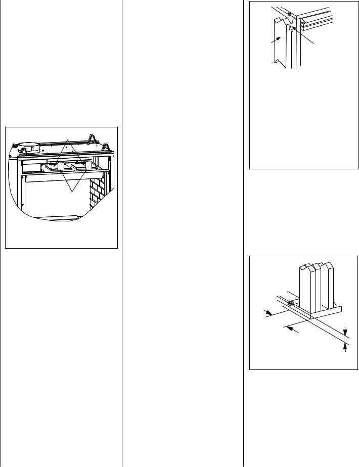
Theapplianceisshippedwithallgascontrolsand components installed and pre-wired. Remove the shipping carton, exposing the front glass door. Remove the top and bottom louvered control panel per instructions on Page 25 (see
Control Compartment Access / Louver Panel Instructions). Remove the cardboard from underneath the pressure relief plates (in area behind top louver panel, See Figure 11). Open the two latches (located under the firebox floor) securing the glass door. Remove the door by tilting it outward at the bottom and lifting it up. Set the door aside protecting it from inadvertent damage. See Figure 57 on Page 29.
Pressure Relief Plates |
|
REMOVE |
REMOVE |
CARDBOARD |
|
CARDBOARD |
BEFOREUSING |
BEFOREUSING |
|
Remove Cardboard Before |
|
Using Appliance |
|
Note: See-Through Model Shown |
|
Figure 11 |
|
TYPICAL INSTALLATION SEQUENCE
The typical sequence of installation follows, however, each installation is unique resulting in variations to those described.
See the Page numbers references in the following steps for detailed procedures.
Step 1. (Page 8) Construct the appliance framing. Position the appliance within the framing and secure with nailing brackets.
Step 2. (Page 8) Route gas supply line to appliance location.
Step 3. (Page 11) Install the vent system and exterior termination.
Step 4. (Page 23) Field Wiring
a.Millivolt Appliances – Install the operating control switch (not factory provided) and bring in electrical service line for forced air circulating blower (optional equipment).
b.Electronic Appliances – Field wire and install operating control switch.
Step 5. (Page 23) Install blower kit (optional equipment).
Step 6. (Page 24) Make connection to gas supply.
Step 7. (Page 25) Install the logs, decorative volcanic stone and glowing embers.
Step 8. (Page 26) Checkout appliance operation.
Step 9. (Page 29) Install glass door frame assembly.
Step 10. (Page 29) Adjust burner to ensure proper flame appearance.
Step 11. (Page 30) Install the hoods.
Step 1. Framing
Frame these appliances as illustrated in Figures 14 & 15 on Pages 9 & 10 (Figure 15 applies to corner framing installations only). All framing details must allow for a minimum clearance to combustible framing members as shown in
Table 8 on Page 7.
If the appliance is to be elevated above floor level, a solid continuous platform must be constructed.
Headers may be in direct contact with the appliance top spacers but must not be supported by them or notched to fit around them. All construction above the appliance must be self supporting. DO NOT use the appliance for structural support.
The fireplace should be secured to the side framing members using the unit's nailing flanges - one top and bottom on each side of the fireplace front. See Figure 12. Use 8d nails or their equivalent.
NOTE: DIAGRAMS & ILLUSTRATIONS ARE NOT TO SCALE.
Side |
Unit Nailing Flange |
(No clearance to |
|
Framing |
combustible |
|
framing is required) |
Left Side Front Corner of Fireplace Shown |
|
(Right Side Requirements the Same) |
|
Unit Being Secured By Its Nailing Flanges |
|
|
To The Framing |
Note: The nailing flanges, combustible members |
|
and screw heads located in areas directly adjacent |
|
to the nailing flanges, are EXEMPT from the 1/2” |
|
clearance to combustible requirements for the |
|
firebox outer wrapper. Combustible framing may be |
|
in direct contact with the nailing flanges and may |
|
be located closer than 1/2” from screw heads and |
|
the firebox wrapper in areas adjacent to the nailing |
|
flanges. Frame the opening to the exact dimensions |
|
specified in the framing details of this manual. |
|
Figure 12
Step 2. Routing Gas Line
Route a 1/2" (13 mm) gas line along the inside of the right side framing as shown in Figure 13. Gas lines must be routed, constructed and made of materials that are in strict accordance with local codes and regulations. All appliances are factory-equipped with a flexible gas line connector and 1/2 inch shutoff valve. (See
Step 6 on Page 24 ).
Right Side Front Corner of Fireplace Framing
3"
6 1/2" (76 mm)
(152 mm) Also see Figure 14.
Figure 13 - ROUTE GAS LINE
Continued on Page 10.
fireplace specifications
|
|
|
|
|
|
|
|
|
|
|
|
|
Framing |
|
|
|
|
|
|
|
|
|
|
|
|
|
|
|
|
|
|
|
|
|
|
|
|
**FRAMING WITH SQUARE HORIZONTAL TERMINATIONS (SV4.5HT-2) |
||||||||||||||||||||||||||||||||||||||||||||||||
|
|
|
|
|
|
|
|
|
|
|
|
|
|
|
|
|
|
|
|
|
|
|
|
|
|
|
|
|
|
|
|
|
|
|
|
|
|
|
|
|
|
|
|
|
|
|
||||||||||||||||||||||||||||||||||||||||
|
|
|
|
|
|
|
|
|
|
|
Framing Dimensions |
|
|
|
|
|
|
|
|
|
|
|
|
|
|
|
|
|
|
|
VENT FRAMING - |
|
|
|
|
|
|
|
|
|
|
|
|
|
|
|
** Framing should be constructed |
|||||||||||||||||||||||||||||||||||||||
|
Model No. |
|
|
|
|
|
|
|
|
A |
|
|
|
|
|
|
|
B |
|
|
C |
|
D |
|
|
|
|
E |
|
|
|
|
|
TOP VENT WITH ONE |
|
|
|
|
|
|
|
|
|
|
|
|
|
|
|
|
|
|
|
|
|
|
of 2x4 or larger lumber |
|||||||||||||||||||||||||||||
|
|
|
|
|
|
|
|
|
|
|
|
|
|
|
|
|
|
|
|
|
|
|
|
|
|
|
|
|
|
|
|
|
|
|
|
|
|
|||||||||||||||||||||||||||||||||||||||||||||||||
|
|
|
|
|
|
|
|
|
|
|
|
|
|
|
|
|
|
|
|
|
|
|
|
|
|
|
|
|
|
|
|
|
|
|
|
|
|
|
|
|
|
|
|
|
|
|
|
|
|
90ϒELBOW |
|
|
|
|
|
|
|
|
|
|
|
|
|
|
|
|
|
|
|
|
|
|
|
10-1/2 |
|
|
|
|
|
|
|
|
|
|
||
|
|
|
|
|
|
|
|
|
in. |
|
33-1/4 |
|
|
|
|
|
33-1/4 |
|
|
|
|
------ |
|
|
37-3/4 |
|
12-7/8 |
|
|
|
|
|
|
|
|
|
|
|
|
|
|
|
|
|
|
|
|
|
|
|
|
|
|
|
|
|
|
|
|
|
|
|
|
|
|
|||||||||||||||||||||
|
LMDVT-3328 |
|
|
|
|
|
|
|
|
|
|
|
|
|
|
|
|
|
|
|
|
|
|
|
|
|
|
|
|
|
|
|
|
|
|
|
|
|
|
|
|
|
|
|
|
(267) |
|
|
|
|
|
|
|
|
|
|
|
|||||||||||||||||||||||||||||
|
|
mm |
|
845 |
|
|
|
|
|
845 |
|
|
|
|
|
------ |
|
|
959 |
|
327 |
|
|
|
|
VENT FRAMING - |
|
|
|
|
|
|
|
|
|
|
|
|
|
|
|
|
|
|
|
|
|
|
|
|
|
|
|
|
|
|||||||||||||||||||||||||||||||
|
|
|
|
|
|
|
|
|
|
|
|
|
|
|
|
|
|
|
|
|
|
|
|
|
|
|
|
|
|
|
|
|
|
|
|
|
|
|
|
|
|
|
|
|
|
|
|
|
|
|
|
|
|
|
||||||||||||||||||||||||||||||||
|
LMDVR-3328 |
|
|
in. |
|
33-1/4 |
|
|
|
|
|
33-1/4 |
|
|
|
|
19-5/8 |
|
------ |
|
12-7/8 |
|
|
|
|
REAR VENT WITH |
|
|
|
|
|
|
|
|
|
|
|
|
|
|
|
|
|
|
|
|
|
|
|
|
|
|
|
|
|
|||||||||||||||||||||||||||||||
|
|
|
|
|
|
|
|
|
|
|
|
|
|
|
|
|
|
|
|
|
|
|
|
|
|
|
|
|
|
|
|
|
|
|
|
|
|
|
|
|||||||||||||||||||||||||||||||||||||||||||||||
|
|
|
|
|
|
|
|
mm |
|
845 |
|
|
|
|
|
845 |
|
|
|
|
|
498 |
|
|
------ |
|
327 |
|
|
|
|
NO ELBOWS |
|
|
|
|
|
|
|
|
|
|
|
|
|
|
|
|
|
|
|
|
|
|
|
|
|
|
|
|
|
|
|
|
|
|
|
|
||||||||||||||||||
|
|
|
|
|
|
|
|
|
|
|
|
|
|
|
|
|
|
|
|
|
|
|
|
|
|
|
|
|
|
|
|
|
|
|
|
|
|
|
|
|
|
|
|
|
|
|
|
|
|
|
|
|
7 |
|
|
|
|
|
|
|
||||||||||||||||||||||||||
|
|
|
|
|
|
|
|
|
|
|
|
|
|
|
|
|
|
|
|
|
|
|
|
|
|
|
|
|
|
|
|
|
|
|
|
|
|
|
|
|
|
|
|
|
|
|
|
|
|
|
|
|
|
|
|
|
|
|
|
|
|
|
|
|
|
|
|
|
|
|
|
|
|
|
|
|
|
|
|
|
|
|
||||
|
|
|
|
|
|
|
|
|
in. |
|
35-1/4 |
|
|
|
|
|
35-1/4 |
|
|
|
|
21-11/16 |
39-3/4 |
|
16 |
|
|
|
|
|
|
|
|
|
|
|
|
|
|
|
|
|
|
|
|
|
|
|
|
|
|
|
|
|
|
|
|
|
|
|
|
|
||||||||||||||||||||||||
|
LMDV-3530 |
|
|
|
|
|
|
|
|
|
|
|
|
|
|
|
|
|
|
|
|
|
|
|
|
|
|
|
|
|
|
|
|
|
|
|
|
|
|
|
|
|
|
5-1/8 |
(178) |
|
|
|
|
|
|
|||||||||||||||||||||||||||||||||||
|
|
mm |
|
895 |
|
|
|
|
|
895 |
|
|
|
|
|
551 |
|
|
1010 |
|
406 |
|
|
|
|
|
|
|
|
|
|
|
|
|
|
|
|
|
|
|
|
|
|
|
|
|
|
|
|
|
|
|
|
|
|
12-1/8 |
|
|
||||||||||||||||||||||||||||
|
|
|
|
|
|
|
|
|
|
|
|
|
|
|
|
|
|
|
|
|
|
|
|
|
|
|
|
|
|
|
|
|
|
|
|
|
|
|
|
|
|
|
|
|
|
|
|
|
|
|
(130) |
|
|
|
|
|
|
|
||||||||||||||||||||||||||||
|
|
|
|
|
|
|
|
|
|
|
|
|
|
|
|
|
|
|
|
|
|
|
|
|
|
|
|
|
|
|
|
|
|
|
|
|
|
|
|
|
|
|
|
|
|
|
|
|
|
|
|
|
|
|
|
|
|
|
|
|
|
|
|
|
|
|
|
|
|
|
|
|
|
|
|
|
|
|
|
|
(308) |
|
|
|||
|
LMDV-4035 |
|
|
in. |
|
40-1/4 |
|
|
|
|
|
40-1/4 |
|
|
|
|
26-11/16 |
44-3/4 |
|
16 |
|
|
|
|
|
|
|
|
|
|
|
|
|
|
|
|
|
|
|
|
|
|
|
|
|
|
|
|
|
|
|
|
|
|
|
|
|
|
|
|
|
|
||||||||||||||||||||||||
|
|
|
|
|
|
|
|
mm |
|
1022 |
|
|
|
|
|
1022 |
|
|
|
|
678 |
|
|
1137 |
|
406 |
|
|
|
|
|
|
|
|
|
|
|
|
|
|
|
|
|
|
|
|
|
|
|
|
|
|
|
|
|
|
|
|
|
|
|
|
|
|
|
|
|
|
||||||||||||||||||
|
|
|
|
|
|
|
|
|
|
|
|
|
|
|
|
|
|
|
|
|
|
|
|
|
|
|
|
|
|
|
|
|
|
|
|
|
|
|
|
|
|
|
|
|
|
|
|
|
|
|
|
|
|
|
|
|
|
|
|
|
|
|
|
|
|
|
|
|
|
|
|
|
|
|
|
|
|
|
|
|
|
|
|
|
|
|
|
|
|
|
|
|
|
|
|
|
|
|
|
|
|
|
|
|
|
|
|
|
|
|
|
|
|
|
|
|
|
|
|
|
|
|
|
|
|
|
|
|
|
|
|
|
|
|
|
|
|
|
|
|
|
|
|
|
|
|
|
|
|
|
|
|
|
|
|
|
|
|
|
|
|
|
|
|
|
|
|
|
|
|
|
|
|
|
|
|
|
|
|
|
|
|
|
|
|
|
|
|
|
|
|
|
|
|
|
|
|
|
|
|
|
|
|
|
|
|
|
|
|
|
|
|
|
|
|
|
|
|
|
|
|
|
|
|
|
|
|
|
|
|
|
|
|
|
|
|
|
|
|
|
|
|
|
|
|
|
|
|
|
7 |
|
|
|
|
|
|
|
|
||
|
|
|
|
|
|
|
|
|
|
|
|
|
Efficiencies % |
|
|
|
|
|
|
|
|
|
|
|
|
|
|
|
|
|
|
|
|
|
|
|
|
|
|
|
|
|
|
|
|
|
|
|
|
|
|
|
|
|
|
|
|
|
|
|
|
|
|
|
|
|
||||||||||||||||||||
|
|
|
|
|
|
|
|
|
|
|
|
Natural Gas |
|
|
|
|
|
|
|
|
|
|
|
|
|
|
Propane |
|
|
|
|
|
|
|
|
|
|
|
|
|
|
|
|
|
|
|
|
|
|
|
|
|
|
|
|
|
5-1/8 |
(178) |
|
|
|
|
|
|
||||||||||||||||||||||
|
|
|
|
|
|
|
|
|
|
|
|
|
|
|
|
|
|
|
|
|
|
|
|
|
|
|
|
|
|
|
|
|
|
|
|
|
|
|
D |
|
|
|
|
|
|
|
|
|
12-1/8 |
|
|
|||||||||||||||||||||||||||||||||||
|
|
|
|
|
|
|
|
|
|
|
|
|
|
|
|
|
|
|
|
|
|
|
|
|
|
|
|
|
|
|
|
|
|
|
|
|
|
|
|
|
|
|
|
|
|
|
|
|
|
|
|
|
|
|
||||||||||||||||||||||||||||||||
|
|
|
|
|
|
|
|
|
|
|
|
|
|
|
|
|
|
|
|
|
|
|
|
|
|
|
|
B |
|
|
|
|
|
|
|
|
|
|
|
|
|
|
|
|
|
|
(130) |
|
|
|
|
|
|
|
||||||||||||||||||||||||||||||||
|
Models |
|
|
P4 |
|
|
Steady |
|
|
AFUE |
|
|
P4 |
|
Steady |
|
|
AFUE |
|
|
|
|
|
|
|
|
|
|
|
|
|
|
|
|
|
|
|
|
|
|
|
|
|
|
|
|
|
|
|
|
|
|
(308) |
|
|
|||||||||||||||||||||||||||||||
|
|
|
|
|
|
|
|
|
|
|
|
|
|
|
|
|
|
|
|
|
|
|
|
|
|
|
|
|
|
|
|
|
|
|
|
|
|
|
|
|
|
|
|
|
|
|
|
|
|
|
|
|
|
|||||||||||||||||||||||||||||||||
|
|
|
|
|
|
|
|
|
|
|
|
|
|
State |
|
|
|
|
|
|
|
|
|
|
|
|
|
|
|
|
State |
|
|
|
|
|
|
|
|
|
|
|
|
|
|
|
|
|
|
|
|
|
|
|
|
|
|
|
|
|
|
|
|
|
|
|
|
|
|
|
|
|
|
|
|
|
|
|
||||||||
|
|
|
|
|
|
|
|
|
|
|
|
|
|
|
|
|
|
|
|
|
|
|
|
|
|
|
|
|
|
|
|
|
|
|
|
|
|
|
|
|
|
|
|
|
|
|
|
|
|
|
|
|
|
|
|
|
|
|
|
|
|
|
|
|
|
|
|
|
|
|
|
|
|
|||||||||||||
|
LMDVT-3328 |
|
|
|
|
|
|
45 |
|
|
64 |
|
|
|
|
|
|
62 |
|
|
|
|
|
|
49 |
|
|
|
66 |
|
64 |
|
|
|
|
|
|
|
|
|
|
|
|
|
|
|
|
|
|
|
|
|
|
|
|
|
|
|
|
|
|
|
|
|
|
|
|
|
|
|
|
|
|
|||||||||||||
|
|
|
|
|
|
|
|
|
|
|
|
|
|
|
|
|
|
|
|
|
|
|
|
|
|
|
|
|
|
|
|
|
|
|
|
|
|
|
|
|
|
|
|
|
|
|
|
|
|
|
|
|
|
|
|
|
|
|
C |
|
|
|
|
|
|
|
|
|
|
|
|
|
|
|
|
|
|
|
|
|
|
|||||
|
LMDVR-3328 |
|
|
|
|
|
|
53 |
|
|
63 |
|
|
|
|
|
|
61 |
|
|
|
|
|
|
55 |
|
|
|
66 |
|
64 |
|
|
|
|
|
|
|
|
|
|
|
|
|
|
|
|
|
|
|
|
|
|
|
|
|
|
|
|
|
|
|
|
|
|
|
|
|||||||||||||||||||
|
|
|
|
|
|
|
|
|
|
|
|
|
|
|
|
|
|
|
|
|
|
|
|
|
|
|
|
|
|
|
|
|
|
|
|
|
|
|
|
|
|
|
|
|
|
|
|
|
|
|
|
|
|
|
|
|
|
|
|
|
|
|
|
|
|
|
|
|
|
|
|
|
|
|
|
|
|
|
|
|
|
|
|
|
|
|
|
LMDV-3530 |
|
|
|
|
|
|
53 |
|
|
64 |
|
|
|
|
|
|
62 |
|
|
|
|
|
|
55 |
|
|
|
62 |
|
60 |
|
|
|
|
|
|
|
|
|
|
|
|
|
|
|
|
|
|
|
|
E |
|
|
|
|
|
|
|
|
|
|
|
|
|
|||||||||||||||||||||
|
LMDV-4035 |
|
|
|
|
|
|
59 |
|
|
69 |
|
|
|
|
|
|
67 |
|
|
|
|
|
|
60 |
|
|
|
69 |
|
67 |
|
|
|
|
|
|
1/2 A |
|
|
|
|
|
|
|
|
|
|
|
|
|
|
|
|
|
|
|
|
|
|
|
|
|
|
|
|
|
|||||||||||||||||||
|
|
|
|
|
|
|
|
|
|
|
|
|
|
|
|
|
|
|
|
|
|
|
|
|
|
|
|
|
|
|
|
|
|
|
|
|
|
|
|
|
|
|
|
|
|
|
|
|
|
|
|
|
|
|
|
|
|
|
|
|
|
|
|
|
|
|
|
|
|
|
|
|
|
|
|
|
|
|
|
|||||||
|
|
|
|
|
|
|
|
|
|
|
|
|
|
|
|
|
|
|
|
|
|
|
|
|
|
|
|
|
|
|
|
|
|
|
|
|
|
|
|
|
|
|
|
|
|
|
|
|
|
|
|
|
|
|
|
|
|
|
|
|
|
|
|
|
|
|
|
|
|
|
|
|
|
|
|
|
|
|
|
|||||||
|
|
|
|
|
|
|
|
|
|
|
|
|
|
|
|
|
|
|
|
|
|
|
|
|
|
|
|
|
|
|
|
|
|
|
|
|
|
|
|
|
|
|
|
|
|
|
|
|
|
|
|
|
|
|
|
A |
|
|
|
|
|
|
|
|
|
|
|
|
|
|
|
|
|
|
|
|
|
|
|
|
|
|
|
|
|
|
|
|
|
|
Notes |
|
|
|
|
|
|
|
|
|
|
|
|
|
|
|
|
Input (BTU) - MV & Electronic |
|
|
Inches (mm) |
|
|
|
|
|
|
|
|
|
|
|
|
|
|
|
|
|
|
|
|
|
|
|
|
|
|
|
|
|
|||||||||||||||||||||||||||||||||
|
|
|
|
|
|
|
|
|
|
|
|
|
|
|
|
|
|
|
|
|
|
|
|
|
|
|
|
|
|
|
|
|
|
|
|
|
|
|
|
|
|
|
|
|
|
|
|
|
|
|
|
|
|
|
|
|
|
|||||||||||||||||||||||||||||
|
* The Steady State Efficiency numbers based on |
|
|
|
|
|
|
|
|
|
|
|
Natural & Propane Gas |
|
|
|
|
|
|
|
|
|
|
|
|
|
|
|
|
|
|
|
|
|
|
|
|
|
|
|
|
|
|
|
|
|
|
|
|
|
|
|
|
|
|
|
||||||||||||||||||||||||||||||
|
|
|
|
|
|
|
|
|
|
|
|
|
|
|
|
|
|
|
|
|
|
|
|
|
|
|
|
|
|
|
|
|
|
|
|
|
|
|
|
|
|
|
|
|
|
|
|
|
|
|
|
|
|
|
|
|
|
|
||||||||||||||||||||||||||||
|
maximum vent configuration. |
|
|
|
|
|
|
|
|
|
|
|
|
|
|
|
|
|
|
|
|
|
|
|
|
|
|
|
|
|
|
|
|
|
|
|
|
|
|
|
|
|
|
|
|
|
|
|
|
|
|
E is the required framing depth dimension when the |
||||||||||||||||||||||||||||||||||
|
|
|
|
|
|
|
|
|
|
|
|
|
|
|
|
|
Models |
|
|
|
|
Input Rate (BTU / HR) |
|
|
|
|
|
|
|
|
|
|
|
|
|
|||||||||||||||||||||||||||||||||||||||||||||||||||
|
Due to Lennox' ongoing commitment to quality, all |
|
|
|
|
|
|
|
|
|
|
|
|
|
|
|
|
|
|
|
|
|
|
|
|
finish material (drywall) thickness is 1/2 in. (13mm). |
||||||||||||||||||||||||||||||||||||||||||||||||||||||||||||
|
|
|
|
|
|
|
|
|
|
|
|
|
|
|
|
|
|
|
|
|
|
|
|
|
|
|
|
|
|
|
|
|
|
|
|
|
|
|
|
|
|
|||||||||||||||||||||||||||||||||||||||||||||
|
specifications, ratings and dimensions are subject |
|
|
|
|
|
LMDVT-3328CPM |
|
|
17,500 |
|
|
|
|
|
|
|
|
|
|
|
|
|
|
|
|
|
|
|
|
|
|
|
|
|
|
|
|
|
|
|
|
|
|
|
|
|
|
|
|
|
|
|
|
|
|
||||||||||||||||||||||||||||||
|
to change without notice. |
|
|
|
|
|
|
|
|
|
|
|
|
|
LMDVR-3328CPM |
|
|
|
|
|
|
|
|
|
|
|
|
|
|
|
|
|
|
|
|
|
|
|
|
|
|
|
|
|
|
|
|
|
|
|
|
|
|
|
|
|
|
|
|
|
|
|
|
|||||||||||||||||||||||
|
|
|
|
|
|
|
|
|
|
|
|
|
|
|
|
|
|
|
|
|
|
|
|
|
|
|
|
|
|
|
|
|
|
|
|
|
|
|
|
|
|
|
|
|
|
|
|
|
|
|
|
|
|
|
|
|
|
|
|
|
|
|
|
|
|
|
||||||||||||||||||||
|
|
|
|
|
|
|
|
|
|
|
|
|
|
|
|
|
|
|
|
|
|
|
|
|
|
|
|
|
|
|
|
|
|
|
|
|
|
|
|
|
|
|
|
|
|
|
|
|
|
|
|
|
|
|
|
|
|
|
|
|
|
|
|
|
|
|
|
|
|
|
|
|
|
|
|
|
|
|
|
|
|
|
|
|
|
|
|
|
|
|
|
|
|
|
|
|
|
|
|
|
|
|
|
|
|
|
|
LMDV-3530CPM |
|
|
20,000 |
|
|
|
|
|
|
|
|
|
|
|
|
|
|
|
|
|
|
|
|
|
|
|
|
|
|
|
|
|
|
|
|
|
|
|
|
|
|
|
|
|
|
|
|
|
|
||||||||||||||||
|
Vent Size |
|
|
|
|
|
|
|
|
|
|
|
|
|
|
|
|
|
|
|
|
|
|
|
|
|
|
|
|
|
|
Vertical Venting Through the Ceiling: |
||||||||||||||||||||||||||||||||||||||||||||||||||||||
|
|
|
|
|
|
|
|
|
|
|
|
|
|
LMDV-4035CPM |
|
|
27,000 |
|
|
|
|
|
|
|
|
|
|
|
|
|
|
|
|
|
|
|
|
|
|
|
|
|
||||||||||||||||||||||||||||||||||||||||||||
|
Co-axial DV |
|
4-1/2" Inner |
|
|
|
|
|
|
|
|
|
|
|
|
|
|
|
|
|
|
|
|
|
|
|
|
|
|
|
|
|
|
|
|
|
|
|
|
|
|
|
|
|
|
|
|
|
|
|
|
|
|
|
|
|
|
|
|
|
|
Frame ceiling opening - Use a plumb line |
||||||||||||||||||||||||
|
Vent Size |
/ 7-1/2" Outer |
|
|
|
FRAMING SPACERS (Top & Sides & Rear) |
|
|
|
|
|
|
|
|
|
|
|
|
|
|
|
|
|
|
|
|
|
|
|
|
|
|
from the |
ceiling above |
the appliance to |
|||||||||||||||||||||||||||||||||||||||||||||||||||
|
|
|
|
|
|
|
|
|
|
|
|
|
|
|
|
|
|
(Louvered Front Model Shown) |
|
|
|
|
|
|
|
|
locate center of the vertical run. Cut and/or |
|||||||||||||||||||||||||||||||||||||||||||||||||||||||||||
|
|
|
|
|
|
|
|
|
|
|
|
|
|
|
|
|
|
|
|
|
|
|
|
|
|
|
G |
|
|
|
|
|
|
|
|
|
|
|
|
|
|
|
|
|
|
|
|
|
|
|
|
|||||||||||||||||||||||||||||||||||
|
|
|
|
|
|
|
|
|
|
|
|
|
|
|
|
|
|
|
|
|
|
|
|
|
|
|
|
|
|
|
|
|
|
|
|
|
|
|
|
|
|
|
|
|
|
|
|
|
|
|
||||||||||||||||||||||||||||||||||||
|
|
|
|
|
|
|
|
|
|
|
|
|
|
|
|
|
|
|
|
|
|
|
|
|
|
|
|
|
|
|
|
|
|
|
|
|
|
|
|
**See Note 1 |
|
|
|
|
|
|
|
|
|
|
|
|
|
|
|
frame an opening, 10-1/2" x 10-1/2" (267 |
||||||||||||||||||||||||||||||
|
|
|
|
|
|
|
|
|
|
|
|
|
|
|
|
|
|
|
|
|
|
|
H |
|
|
|
|
|
|
|
|
|
|
|
|
|
|
|
|
|
|
|
|
|
|
|
|
|
|
|
|
|
|
|
||||||||||||||||||||||||||||||||
|
|
|
|
|
|
|
|
|
|
|
|
|
|
|
|
|
|
|
|
|
|
|
|
|
|
|
|
|
|
|
|
|
|
|
|
|
|
|
|
|
|
|
|
|
|
|
|
|
|
|
|
|
|
mm x 267 mm) inside dimensions, about |
||||||||||||||||||||||||||||||||
|
|
|
|
|
|
|
|
|
|
|
|
|
|
|
|
|
|
|
|
|
|
|
|
|
|
|
|
|
|
|
|
|
|
|
|
|
|
|
|
|
|
|
*CONCENTRIC FLUE |
|
|
|
|
|
|
|
|
|||||||||||||||||||||||||||||||||||
|
|
|
|
|
|
|
|
|
|
|
|
|
|
|
|
|
|
|
|
|
|
|
|
|
|
|
|
|
|
|
|
|
|
|
|
|
|
|
|
|
|
|
|
|
|
|
|
|
FLUE - 4-1/2 (114) |
|
|
|
|
|
|
|
|
this center mark (see Figure 25). |
|
|
||||||||||||||||||||||||||
|
|
|
|
|
|
|
|
|
|
|
|
|
|
|
|
|
|
|
|
|
|
|
|
|
|
|
|
|
|
|
|
|
|
|
|
|
|
|
|
|
|
|
|
|
|
|
|
|
COMBUSTION AIR - 7-1/2 (190) |
|
|
|
|
|
|
|
|
|
|
|
|
|
|
|
|
|
|
|
|
|
|
|||||||||||||||
|
|
|
|
|
|
|
|
|
|
|
|
|
|
|
|
|
|
|
|
|
|
|
|
|
|
|
|
|
|
|
|
|
|
|
|
|
|
|
|
|
|
|
|
|
|
|
|
* LMDV models have a top and rear vent |
|
|
|
|
|
|
|
|
|
|
|
|
|
|
|
|
|
|
|
|
|
|
||||||||||||||||
|
|
|
|
|
|
|
|
|
|
|
|
|
|
|
|
|
|
|
|
|
|
|
|
|
|
|
|
|
|
|
|
|
|
|
|
|
|
|
|
|
|
|
|
|
|
|
|
|
|
|
|
|
|
|
|
|
|
|
|
|
|
|
|
|
|
|
|
|
|
|||||||||||||||||
|
|
|
|
|
|
|
|
|
|
|
|
|
|
|
|
|
|
|
|
|
|
|
|
|
|
|
|
|
|
|
|
|
|
|
|
|
|
|
|
|
|
|
|
|
|
|
|
|
LMDVR models have only a rear vent |
|
|
|
|
|
|
|
|
|
|
|
|
|
|
|
|
|
|
|
|
|
|
|||||||||||||||
|
|
|
|
|
|
|
|
|
|
|
|
|
|
|
|
|
|
|
|
|
|
|
|
|
|
|
|
|
|
|
|
|
|
|
|
|
|
|
|
|
|
|
|
|
|
|
|
|
LMDVT models have only a top vent |
|
|
|
|
|
|
|
|
|
|
|
|
|
|
|
|
|
|
|
|
|
|
|||||||||||||||
|
|
|
|
|
|
|
|
|
|
|
|
|
|
|
|
|
|
|
|
|
|
|
|
|
|
|
|
|
|
|
|
|
|
|
|
|
|
|
|
|
J |
|
|
**Note 1 - Collars protrude one inch on LMDVR-3328 model. |
|
|
|
|
|
|
|
|
|
|
|
|
|
|||||||||||||||||||||||||||||
|
|
|
|
|
|
|
|
|
|
|
|
|
|
|
|
|
|
|
|
|
|
|
Top View |
|
|
|
|
|
|
|
|
|
|
|
|
|
|
NOTE - Eyebrow |
|
|
|
|
|
|
N |
|
|
|
|
|
|
|
|
|
|
|
|
|
|
|
|
|
|
|
|
|
|
|||||||||||||||||||
|
|
|
|
|
|
|
|
|
|
|
|
|
|
|
|
|
|
|
|
|
|
|
|
|
|
|
|
|
|
|
|
|
|
|
|
|
|
|
|
|
|
|
|
|
|
|
|
|
|
|
|
|
|
|
|
|
|
|
|
|
|
|
|
|||||||||||||||||||||||
|
|
|
|
|
|
|
|
|
|
|
|
|
|
|
|
|
|
|
|
|
|
|
|
|
|
|
|
|
|
|
|
|
|
|
|
|
|
|
|
|
|
|
|
|
|
|
|
|
|
|
|
|
|
|
|
|
|
|
|
|
|
|
|
|||||||||||||||||||||||
|
|
|
|
|
|
|
|
|
|
|
|
|
|
|
|
|
|
|
|
|
|
|
|
|
|
|
|
|
|
|
|
|
|
|
|
|
|
|
|
|
|
|
|
|
|
|
|
|
|
|
|
|
|
|
|
|
|
|
|
|
|
|
||||||||||||||||||||||||
|
|
|
|
|
|
|
|
|
|
|
|
|
|
|
|
|
|
|
|
|
|
|
|
|
|
|
|
|
|
|
|
|
|
|
|
|
|
|
|
3 (76) |
|
|
|
|
|
|
hood shown as positioned |
|
|
|
|
|
|
|
|
|
|
|
|
|
|
|
|
|
1/2 (13) |
|
|
|
|
|
|
|
|
|||||||||||||
|
|
|
|
|
|
|
|
|
|
|
|
|
|
|
|
|
|
|
|
|
|
|
|
|
|
|
E |
|
|
|
|
|
|
|
|
|
|
|
|
|
|
|
in louvered front model. |
|
|
|
|
|
|
|
|
|
|
|
|
|
|
|
|
|
|
|
|
|
|
|
|
|
||||||||||||||||||
|
|
|
|
|
|
|
|
|
|
|
|
|
|
|
|
|
|
|
|
|
|
|
|
|
|
|
|
|
|
|
|
|
|
|
|
|
|
|
|
ELECTRICAL INLET |
|
|
|
|
|
|
|
|
|
|
|
|
|
|
|
|
|
|
|
|
|
|
|
|
|
|
|
|
|
|
|
|
|
|
|
|
||||||||||
|
|
|
|
|
|
|
|
|
|
|
|
|
|
|
|
|
|
|
|
|
|
|
|
|
|
|
|
|
|
|
|
|
|
|
|
|
|
|
|
|
|
|
|
|
|
|
|
|
|
|
|
|
|
|
|
|
|
|
|
|
|
|
|
|
|
|
|
|
|
|
|
|
|
|
|
|
|
|
|
|||||||
|
|
|
|
|
|
|
|
|
|
|
|
|
|
|
|
|
|
|
|
|
|
|
|
|
|
|
|
|
|
|
|
|
|
|
|
|
|
|
|
|
|
|
|
2-3/4 x 2 (70 x 51) |
|
|
|
|
|
|
|
|
|
|
|
|
|
|
|
|
|
|
|
|
|
|
|
|
|
|
|
|
|
|
|
|
|
|
|
|
||||||
|
|
|
|
|
|
|
|
|
|
|
|
|
|
|
|
|
|
|
|
|
|
|
|
|
|
|
|
|
|
|
|
|
|
|
|
|
|
|
|
|
|
|
|
COVER PLATE with |
|
|
|
|
|
|
|
|
|
|
|
|
|
|
|
|
|
|
|
|
|
|
** See Note 1 |
|
|
|
|
|
|
|||||||||||||
|
|
|
|
|
|
|
|
|
|
|
|
|
|
|
|
|
|
|
|
|
|
|
|
|
|
|
|
|
|
|
|
|
|
|
|
|
|
|
|
|
|
|
|
KNOCKOUT) |
|
|
|
|
|
|
|
|
|
|
|
|
|
|
|
|
|
|
|
|
|
|
|
|
|
|
|
|
||||||||||||||
|
|
|
|
|
|
|
|
|
|
|
|
|
|
|
|
|
|
|
|
|
|
|
|
|
|
|
|
|
|
|
|
|
|
|
|
|
|
|
|
|
|
|
|
|
|
|
|
|
|
|
|
|
|
|
|
|
|
|
|
|
|
|
|
|
|
|
|
|
|
|
|
|||||||||||||||
|
|
|
|
|
|
|
|
|
|
|
|
|
|
|
|
|
|
|
|
|
|
|
|
|
|
|
|
|
|
|
|
|
|
|
|
|
|
|
|
|
|
|
|
|
|
|
|
|
GAS INLET |
|
|
|
|
|
|
|
|
|
|
|
|
|
|
|
|
|
|
|
|
|
|
|
|
|
|
|
|
|
|
|
|
|
|
|
|
|
|
|
|
|
|
|
|
|
|
|
|
|
|
|
|
|
|
|
|
|
|
|
|
|
|
|
|
|
|
|
|
|
|
|
|
|
|
|
|
|
|
|
|
|
|
|
|
|
(Either Side |
|
|
|
|
|
|
|
|
|
|
|
|
|
|
6 (152) |
|
|
|
|
|
|
|
|
|
|
|
|
|
|
|
|
|
||||||
|
|
|
|
|
|
|
|
|
|
|
|
|
|
|
|
|
|
|
|
|
|
|
|
|
|
|
|
|
|
|
|
|
|
|
|
|
|
|
|
|
|
|
|
|
|
|
|
and bottom) |
|
|
|
|
|
|
|
|
|
|
|
|
|
|
|
|
|
|
|
|
|
|
|
|
|
|
|
|
|
|
|
|
|
|
|
|
||
|
|
|
|
|
|
|
|
|
|
|
|
A |
|
|
|
|
|
|
|
|
|
|
|
|
|
|
|
C |
|
|
|
|
|
B |
OPTIONAL ELECTRICAL |
|
|
|
|
|
|
|
|
|
|
|
|
|
|
|
L |
|
|
|
|
|
|
|
|
|
|
|
|
|
|
|
|
|
|
|||||||||||||||||
|
|
|
|
|
|
|
|
|
|
|
|
|
|
|
|
|
|
|
|
|
|
|
|
|
|
|
|
|
|
|
|
|
|
|
|
|
|
|
INLET KNOCKOUT, |
|
|
|
|
|
|
|
|
|
|
|
|
|
|
|
|
|
1-5/8 |
|
F** |
|
|
|
|
|
|
|||||||||||||||||||||
|
|
|
|
|
|
|
|
|
|
|
|
|
|
|
|
|
|
|
|
|
|
|
|
D |
|
|
|
|
|
|
|
|
|
|
|
|
|
|
|
|
|
REQUIRING A FIELD |
|
|
|
|
|
|
|
|
|
|
|
|
|
|
|
|
|
|
|
|
|
|
|
|
|
|
|
|
|
|
||||||||||||||
|
|
|
|
|
|
|
|
|
|
|
|
|
|
|
|
|
|
|
|
|
|
|
|
|
|
|
|
|
|
|
|
|
|
|
|
|
|
|
|
|
|
|
|
PROVIDED JUNCTION BOX |
1-3/8 (35) |
|
|
|
|
|
|
|
|
|
|
|
|
|
|
|
|
(42) |
|
|
|
|
|
|
|
|
|
|
|
|||||||||||||
|
|
|
|
|
|
|
|
|
|
|
|
|
|
|
|
|
|
|
|
|
|
|
|
|
|
|
|
|
|
|
|
|
|
|
|
|
|
|
|
|
|
|
|
|
|
|
|
|
(Either Side) |
|
|
|
|
|
|
|
|
|
|
|
|
|
|
|
|
|
M |
|
|
|
|
|
|
|
|
|
|
|
||||||||
|
|
|
|
|
|
|
|
|
|
|
|
|
|
|
|
|
|
|
|
|
|
|
|
|
|
|
|
|
|
|
|
|
|
|
|
|
|
|
|
|
|
|
|
|
|
|
|
|
|
|
K |
|
|
|
|
|
|
|
|
|
|
|
|
|
|
|
|
|
|
|
|
|
|
|
|
|
|
|
|
|
|
|
|
|
||
|
|
|
|
|
|
|
|
|
|
|
|
|
|
|
|
|
|
|
|
|
|
|
|
|
|
|
|
|
|
|
|
|
|
|
|
|
|
|
|
|
|
|
|
|
|
|
|
|
|
|
|
|
|
|
|
|
|
|
|
|
|
|
|
|
|
|
|
|
|
|
|
|
|
|
|
|
|
|
|
|
|
|
|
|||
|
|
|
|
|
|
|
|
|
|
|
|
|
|
|
|
|
|
|
|
|
|
|
|
|
|
|
|
|
|
|
|
|
|
|
|
|
|
|
|
|
|
|
|
|
|
|
|
|
|
|
|
|
|
|
|
|
|
|
|
|
|
|
|
|
|
|
|
|
|
|
|
|
|
|
|
|
|
|
|
|
|
|||||
|
|
|
|
|
|
|
|
|
|
|
|
|
|
|
|
|
|
|
|
|
|
|
|
|
|
|
|
|
|
|
|
|
|
|
|
|
|
|
|
|
|
|
|
|
|
|
|
|
|
|
|
|
|
|
|
|
|
|
|
|
|
|
|
|
|
|
|
|
|
|
|
|
|
|
|
|
|
|
|
|
|
|
|
|
|
|
|
|
|
|
|
|
|
|
|
|
|
|
|
|
|
|
|
|
|
|
|
|
|
Front View |
|
|
|
|
|
|
|
|
|
|
|
|
|
|
|
|
|
|
|
|
|
|
|
Right Side View |
|
|
|
|
|
|
|
|
|
|
|
|
|
||||||||||||||||||||||||||
|
|
|
|
|
|
|
|
|
|
|
|
|
|
|
|
|
|
|
|
|
|
|
|
|
|
|
|
|
|
|
|
|
|
|
|
|
|
|
|
|
|
|
|
|
|
|
|
|
|
|
|
|
|
|
|
|
|
|
||||||||||||||||||||||||||||
|
|
|
|
|
|
|
|
|
|
|
|
|
|
|
|
|
|
|
|
|
|
|
|
|
|
|
|
|
|
|
|
|
|
|
|
|
|
|
|
|
|
|
|
|
|
|
|
|
|
|
|
|
|
|
|
|
|
|
|
|
|
|
|
|
|
|
|
|
|
|
|
|
|
|
|
|
|
|
|
|
|
|
|
|
|
|
|
|
|
|
|
|
|
|
Model No. |
|
|
|
|
|
|
|
|
A |
|
B |
|
C |
|
D |
|
|
E |
|
**F |
|
|
|
|
G |
|
|
H |
|
|
|
|
|
J |
|
K |
|
|
|
|
L |
|
|
M |
N |
|
||||||||||||||||||||||||||||||||
|
|
|
|
|
|
|
|
LMDVT-3328 |
in. |
|
33 1/8 |
|
|
|
30 1/8 |
17 |
27 1/2 |
33 1/8 |
|
19 5/8 |
|
21 1/2 |
10 3/4 |
|
6 13/16 |
3 |
|
8 11/32 |
|
2 3/4 |
13 |
|
||||||||||||||||||||||||||||||||||||||||||||||||||||||
|
|
|
|
|
|
|
|
LMDVR-3328 |
|
mm |
|
841 |
|
|
|
765 |
|
|
432 |
699 |
841 |
|
|
498 |
|
546 |
|
273 |
|
|
|
173 |
|
76 |
|
212 |
|
70 |
330 |
|
||||||||||||||||||||||||||||||||||||||||||||||
|
|
|
|
|
|
|
|
|
|
|
|
|
|
|
|
|
|
|
|
|
|
|
|
|
|
|
|
|
|
|
|
|
|
|
|
|
|
|
|
|
|
|
|
|
|
|
|
|
|
|
|
|
|
|
|
|
|
|
|
|
|
|
|
|
|
|
|
|
|
|
|
|
|
|
|
|
|
|
|
|
|
|
|
|
||
|
|
|
|
|
|
|
|
LMDV-3530 |
|
in. |
|
35 1/8 |
|
|
|
32 1/8 |
19 |
29 1/2 |
35 1/8 |
|
21 11/16 |
|
24 7/8 |
12 7/16 |
|
9 |
|
|
|
3 |
|
9 |
|
3 |
16 |
|
||||||||||||||||||||||||||||||||||||||||||||||||||
|
|
|
|
|
|
|
|
|
|
|
|
|
|
|
|
|
|
|
|
|
|
|
|
|
|
|
|
|
|
|
|
|
|
|
|
|
|
|
|
|
|
|
|
|
|
|
|
|
|
|
|
|
|
|
|
|
|
|
|
|
|
|
|
|
|
|
|
|
|
|
|
|
|
|
|
|
|
|
||||||||
|
|
|
|
|
|
|
|
|
mm |
|
892 |
|
|
|
816 |
|
|
483 |
749 |
892 |
|
|
551 |
|
632 |
|
316 |
|
|
|
220 |
|
76 |
|
220 |
|
76 |
406 |
|
|||||||||||||||||||||||||||||||||||||||||||||||
|
|
|
|
|
|
|
|
|
|
|
|
|
|
|
|
|
|
|
|
|
|
|
|
|
|
|
|
|
|
|
|
|
|
|||||||||||||||||||||||||||||||||||||||||||||||||||||
|
|
|
|
|
|
|
|
LMDV-4035 |
|
in. |
|
40 1/8 |
|
|
|
37 1/8 |
24 |
34 1/2 |
40 1/8 |
|
26 11/16 |
|
29 7/8 |
14 15/16 |
|
9 |
|
|
|
3 |
|
9 |
|
3 |
16 |
|
||||||||||||||||||||||||||||||||||||||||||||||||||
Figure 14 |
|
|
|
|
|
|
|
|
|
|
|
|
|
|
|
mm |
|
1019 |
|
|
|
943 |
|
|
610 |
876 |
1019 |
|
|
678 |
|
759 |
|
379 |
|
|
|
220 |
|
76 |
|
220 |
|
76 |
406 |
|
||||||||||||||||||||||||||||||||||||||||
|
|
|
|
|
|
|
|
|
|
|
|
|
|
|
|
|
|
|
|
|
|
|
|
|
|
|
|
|
|
|
|
|
|
|
|
|
|
|
|
|
|
|
|
|
|
|
|
|
|
|
|
|
|
|
|
|
|
|
|
|
|
|
|
|
|
|
|
|
|
|
|
|
|
|
|
|
|
|
|
|
|
|
|
|
|
|
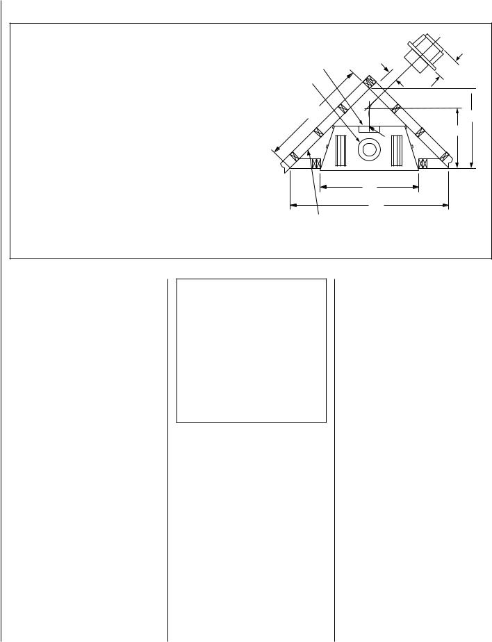
fireplace FRAMING specifications
Note-
Venting requirments for rear vent applications in corner installations -
• The horizontal vent length "a" to "b" must not exceed 28 inches (711 mm).
LMDVT-3328 and LMDVR-3328 Models -
Dimension A to F occur when one 45 degree elbow is connected directly to the appliance collar.
LMDVT-3530 and LMDVR-4035 Models -
Dimension D and F occur when one 45 degree elbow is connected directly to the appliance collar.
Model No. |
|
|
A |
B |
C |
|
D |
E |
|
F |
|
|
|
|
|
|
|
|
|
|
|
LMDVT-3328 |
in. |
33 |
1/8 |
48 1/2 |
34 5/16 |
17 |
3/16 |
241/4 |
|
5 |
LMDVR-3328 |
mm |
841 |
1232 |
872 |
437 |
616 |
127 |
|||
LMDV-3530 |
in. |
35 |
1/8 |
57 1/2 |
40 5/8 |
19 |
3/16 |
28 3/4 |
6 |
1/8 |
|
|
|
|
|
|
|
||||
mm |
892 |
1461 |
1032 |
487 |
730 |
156 |
||||
|
|
|
|
|
|
|
|
|
|
|
LMDV-4035 |
in. |
40 |
1/8 |
6 13/16 |
43 11/32 |
19 |
3/16 |
30 11/16 |
7 |
7/8 |
|
|
|
|
|
|
|
||||
mm |
1019 |
1554 |
1101 |
487 |
779 |
200 |
||||
 b
b
LMDV and LMDVR units |
F |
||
7 1/4 (184) |
|||
|
|
||
LMDV and LMDVT units |
|
||
Inches |
|
|
|
(millimeters) |
C |
E |
|
|
|
||
D
a
A
B
Back wall of chase/enclosure (including any finishing materials)
Figure 15 - Corner Framing with Square Termination (SV4.5HT-2)
Proper Sizing of Gas Line
Properly size and route the gas supply line from the supply regulator to the area where the appliance is to be installed per requirements outlined in the National Fuel Gas Code, NFPA 54 - latest edition (USA) or B149 - latest edition (Canada).
Never use galvanized or plastic pipe. Refer to Table 9 for proper sizing of the gas supply line, if black iron pipe is being used. Gas lines must be routed, constructed and made of materials that are in strict accordance with local codes and regulations. We recommend that a qualified individual such as a plumber or gas fitter be hired to correctly size and route the gas supply line to the appliance. Installing a gas supply line from the fuel supply to the appliance involves numerous considerations of materials, protection, sizing, locations, controls, pressure, sediment, and more. Certainly no one unfamiliar and unqualified should attempt sizing or installing gas piping.
Schedule 40
Black Iron Pipe
Inside Diameter (Inches)
Schedule 40 Pipe |
Natural |
Propane |
Length (feet) |
Gas |
Gas |
0-10 |
1/2 |
3/8 |
|
|
|
10-40 |
1/2 |
1/2 |
|
|
|
40-100 |
1/2 |
1/2 |
100-150 |
3/4 |
1/2 |
150-200 |
3/4 |
1/2 |
|
|
|
Table 9
Notes:
•All appliances are factory-equipped with a flexible gas line connector and 1/2 inch shutoff valve (see Figure 48 on Page 24 ).
•See Massachusetts Requirements on Page 4 for additional requirements for installations in the state of Massachusetts in the USA.
•The gas supply line should Not be connected to the appliance until Step 6 (Page 24 ).
•A pipe joint compound rated for gas should be used on the threaded joints. Ensure propane resistant compounds are used in propane applications. Be very careful that the pipe compound does not get inside the pipe.
•It is recommended to install a sediment trap in the supply line as close as possible to the appliance (see Figure 48 ). Appliances using Propane should have a sediment trap at the base of the tank.
•Check with local building official for local code requirements(i.e.arebelowgradepenetrations of the gas line allowed?, etc).
IMPORTANT: If propane is used, be aware that if tank size is too small (i.e. under 100-lbs, if this is the only gas appliance in the dwelling. Ref. NPFA 58), there may be loss of pressure, resulting in insufficient fuel delivery (which can result in sooting, severe delayed ignition or other malfunctions). Any damage resulting from an improper installation, such as this, is not covered under the limited warranty.
10 |
NOTE: DIAGRAMS & ILLUSTRATIONS ARE NOT TO SCALE. |
Step 3. Install the Vent System
General Information
These instructions should be used as a guideline and do not supersede local codes in any way. Install vent according to local codes, these instructions, the current National Fuel Gas Code (ANSI-Z223.1) in the USA or the current standards of CAN/CGA-B149.1 and -B149.2 in Canada.
Useonlyapprovedventingcomponents. See
Approved Vent Components on Page 2.
These fireplaces must be vented directly to the outside.
The vent system may not service multiple appliances, and must never be connected to a flue serving a solid fuel burning appliance. The vent pipe is tested to be run inside an enclosing wall (such as a chase). There is no requirement for inspection openings in the enclosing wall at any of the joints in the vent pipe.
Preparing the Appliance Vent Collar on LMDV-
3530/4035 Series (Combined Top and Rear
Vent) Models.
Each of the unit's two vent collars are sealed with a cover plate and a seal plate and gasket. The cover, and seal plate and gasket must be removed from the vent collar being used. Refer to Figure 16 for top vent usage and Figure 17 for rear, and the following steps to prepare the appropriate collar for use.
From the vent collar being used, remove the four screws securing the vent seal plate and gasket. Remove and discard the seal plate and gasket.
When the top vent collar is being used, from inside the firebox, loosen the two screws in the keyhole slots of the cover plate and remove the remaining two cover plate securing screws. Remove and discard the cover plate. Reinstall and securely tighten all four screws.
 WARNING
Failure to reinstall and securely tighten cover plate screws could result in leakage of flue products into the living space. Vent cover plate and vent seal plate must remain securely installed on unused vent collar. Failure to do so could result in leakage of flue products into living space.
When the rear vent collar is being used, from inside the firebox, remove the two screws securing the lintel to the rear wall of the firebox, then remove the lintel. Remove the four cover plate securing screws.
Remove and discard the cover plate. Reinstall and securely tighten all four cover plate screws. Re-secure the lintel to the rear wall of the firebox.
On LMDV-3530/4035 Series Models (Combined Top And Rear Vent Units) Top Vent Seal & Cover Plate Removal When Using The Top Vent
(OUTSIDE of |
Gasket Vent Seal Plate |
|
Appliance) |
||
Cabinet Top |
Securing |
|
Screws |
||
|
||
|
Top Vent |
|
Firebox Top |
|
|
Vent Cover Plate |
Cover Plate |
|
|
Securing Screws |
(Inside of Appliance)
CROSS SECTION
Figure 16
On LMDV-3530/4035 Series Models (Combined Top And Rear Vent Units)
Rear Vent Seal & Cover Plate Removal
When Using The Rear Vent
Cover Plate |
Vent Seal Plate |
|
Securing Screws |
||
|
||
Gasket |
||
(INSIDE of |
|
|
Appliance) |
Securing |
|
|
||
Rear Vent |
Screws |
|
|
||
Lintel |
|
|
Lintel |
Cabinet |
|
Securing |
Back |
|
Screws |
(OUTSIDE of |
|
CROSS SECTION |
||
Appliance) |
||
Figure 17
Installation of Vent Restrictor
A vent restrictor may be needed with this appliance, install vent restrictor (provided) in the appliance top flue outlet as shown in Figure 18
(LMDV-3328, LMDV-3530 and LMDV-4035) or rear flue outlet as shown in Figure 19 (LMDV3328, LMDV-3530 and LMDV-4035). It is held in place by friction, only.
NOTE: DIAGRAMS & ILLUSTRATIONS ARE NOT TO SCALE.
Vent Restrictor Installation
(Top Vent)
A vent restrictor may be needed when vertically terminating the vent system above the roof (when using the appliance top vent), install vent restrictor in the top vent of the fireplace outlet on LMDV-3530/4035 and LMDVT-3328 series models. If needed, install the restrictor orientated as shown, either from inside or outside the unit,in the inner fireplace collar.
Restrictor
Inner
Fireplace
Collar Appliance Top
Vent Outlet
Figure 18
Vent Restrictor Installation
(Rear Vent)
A vent restrictor may be needed when horzontally terminating the vent system from the rear of the appliance (when using the appliance rear vent), install vent restrictor in the rear vent of the fireplace outlet on LMDV(R)-3328/3530/4035 series models, in any installation that has a vertical vent run in excess of three feet (0.914 meters).
If needed, install the restrictor orientated as shown, either from inside or outside the unit, in the inner fireplace collar
Inner Fireplace |
Appliance Rear |
|
Collar |
||
Vent Outlet |
||
|
||
|
Restrictor |
Figure 19
Select Venting System - Horizontal or Vertical
With the appliance secured in framing, determine vent routing and identify the exterior termination location. The following sections describe vertical (roof) and horizontal (exterior wall) vent applications. Refer to the section relating to your installation. A list of approved venting components is shown on Pages 31 and 32.
11
 Loading...