


CBWMV
INSTALLATION
E2006 Lennox Industries Inc.
Dallas, Texas, USA
RETAIN THESE INSTRUCTIONS
FOR FUTURE REFERENCE
WARNING
Due to higher operating pressures, CBWMV units
must not be applied to steam boiler systems.
CAUTION
Unit is designed to be used with non−potable boiler
systems only.
CAUTION
Physical contact with metal edges and corners
while applying excessive force or rapid motion can
result in personal injury. Be aware of, and use
caution when working near these areas during
installation or while servicing this equipment.
Introduction
The multi−positional Dave Lennox Signaturet Collection
CBWMV air handler/hot water coil unit is designed to be
used with non-potable boiler systems for warm air heating.
A variety of Lennox air conditioning systems may be applied to the CBWMV unit for optional cooling.
INSTRUCTIONS
CBWMV Series Units
AIR HANDLERS
505,047M
09/06
Supersedes 02/06
Table of Contents
Introduction 1. . . . . . . . . . . . . . . . . . . . . . . . . . . . . . . . . . .
Shipping & Packing List 1. . . . . . . . . . . . . . . . . . . . . . . .
CBWMV Unit Dimensions 2. . . . . . . . . . . . . . . . . . . . . .
General 3. . . . . . . . . . . . . . . . . . . . . . . . . . . . . . . . . . . . . .
CBWMV Unit Parts Arrangement 3. . . . . . . . . . . . . . . .
CBWMV Unit Parts Description 3. . . . . . . . . . . . . . . . . .
CBWMV Unit Optional Accessories 3. . . . . . . . . . . . . .
Requirements 4. . . . . . . . . . . . . . . . . . . . . . . . . . . . . . . . .
Application 4. . . . . . . . . . . . . . . . . . . . . . . . . . . . . . . . . . .
Installation − Setting Equipment 4. . . . . . . . . . . . . . . . . .
Duct System 5. . . . . . . . . . . . . . . . . . . . . . . . . . . . . . . . . .
Return Air Opening Guidelines 6. . . . . . . . . . . . . . . . . .
Filter Assembly & Filters 8. . . . . . . . . . . . . . . . . . . . . . .
Plumbing 8. . . . . . . . . . . . . . . . . . . . . . . . . . . . . . . . . . . . .
Electrical 8. . . . . . . . . . . . . . . . . . . . . . . . . . . . . . . . . . . . .
Freezestat Operation 12. . . . . . . . . . . . . . . . . . . . . . . . . .
BDC3 Variable Blower Control Board 12. . . . . . . . . . . . .
Blower Speed Adjustments 12. . . . . . . . . . . . . . . . . . . . .
Initial Air System Purging 16. . . . . . . . . . . . . . . . . . . . . . .
System Adjustments 17. . . . . . . . . . . . . . . . . . . . . . . . . . .
Annual Service 17. . . . . . . . . . . . . . . . . . . . . . . . . . . . . . . .
Service Filters 17. . . . . . . . . . . . . . . . . . . . . . . . . . . . . . . .
Winterizing the CBWMV Unit 17. . . . . . . . . . . . . . . . . . . .
Repair Parts List 17. . . . . . . . . . . . . . . . . . . . . . . . . . . . . .
Troubleshooting:
Continuous Fan Sequence of Operation 18. . . . . . . . . .
Cooling Sequence of Operation 19. . . . . . . . . . . . . . . . .
Heating Sequence of Operation 20. . . . . . . . . . . . . . . . .
Shipping & Packing List
1 − CBWMV Air Handler [NOTE − Includes freezestat
mounted to the manifold.]
1 − Bag assembly containing:
1 − Electrical make−up box
1 − Copper fitting
1 − Snap bushing
2 − Water line grommets
3 − Wire nuts
2−7/8" cabinet plugs
Check equipment for shipping damage. If you find any
damage, immediately contact the last carrier.
Litho U.S.A.
09/06 505,047M
Page 1
*2P0906* *P505047M*
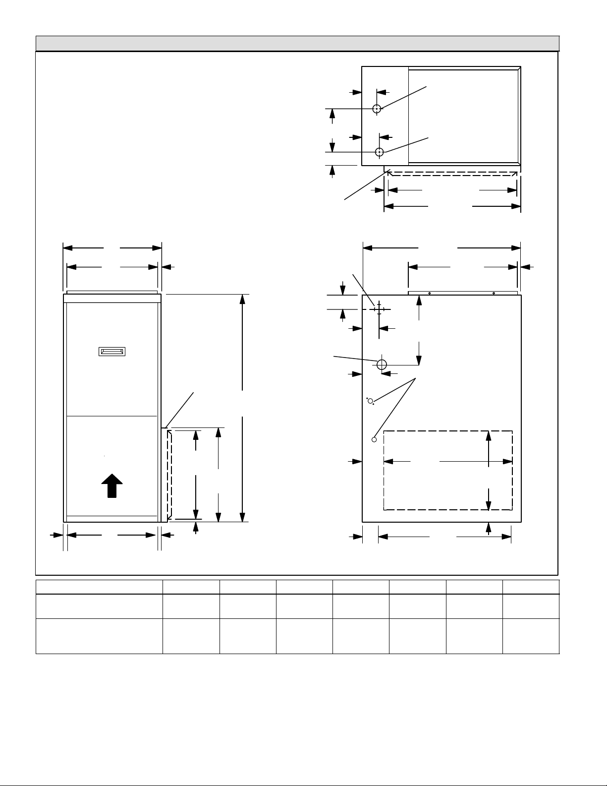
CBWMV Unit Dimensions − inches (mm)
*NOTE − Single side inlet applications result in approximately
4 percent reduction of CFM on B−size units and approximately
5 percent reduction of CFM on C−size units.
OPTIONAL EXTERNAL SIDE RETURN
AIR FILTER KIT (Either Side) − Not for
use with optional Return Air Base.
WATER INLET
G
SUPPLY AIR
OPENING
F
D
E
WATER OUTLET
23-3/4 (603)
25 (635)
TOP VIEW
3/4 (19)
A
B
AIR FLOW
C
*Bottom Return
Air Opening
FRONT VIEW SIDE VIEW
3/4 (19)
9/16
(14)
OPTIONAL
EXTERNAL
SIDE RETURN
AIR FILTER KIT
(Either Side)
14−3/4
(375)
16
(406)
5/8
(16)
40
(1016)
ALTERNATE WATER
INLET (far side)
1−1/4" (32)
1−3/4" (44)
ALTERNATE
WATER OUTLET
2"
(51)
4
(102)
RETURN CUTOUT
4−1/4
*Bottom Return Air Opening
(108)
28−1/2
(724)
19−7/16
(494)
10−1/2"
(267)
ELECTRICAL INLET
(Either Side)
23
(584)
*OPTIONAL
(Either Side)
23−1/2
(597)
9/16
(14)
14
(356)
1−15/16 (49)
CBWMV Model No. A B C D E F G
−24B−040
−36B−070
17−1/2 (445) 16−3/8 (416) 16 (406) 1−1/2 (38) 1−3/4 (44) 8 (203) 2 (51)
−36C−090
−60C−100
21 (533) 19−7/8 (454) 19−1/2 (495) 2 (51) 2−1/2 (64) 9−1/2 (241) 1−1/2 (38)
−60C−120
Page 2
505047 09/06
General
CBWMV Unit Parts Description
These instructions are intended as a general guide and do
not supersede local codes in any way. Consult authorities
having jurisdiction before installation. Only qualified service technicians or installers may install and service this
unit.
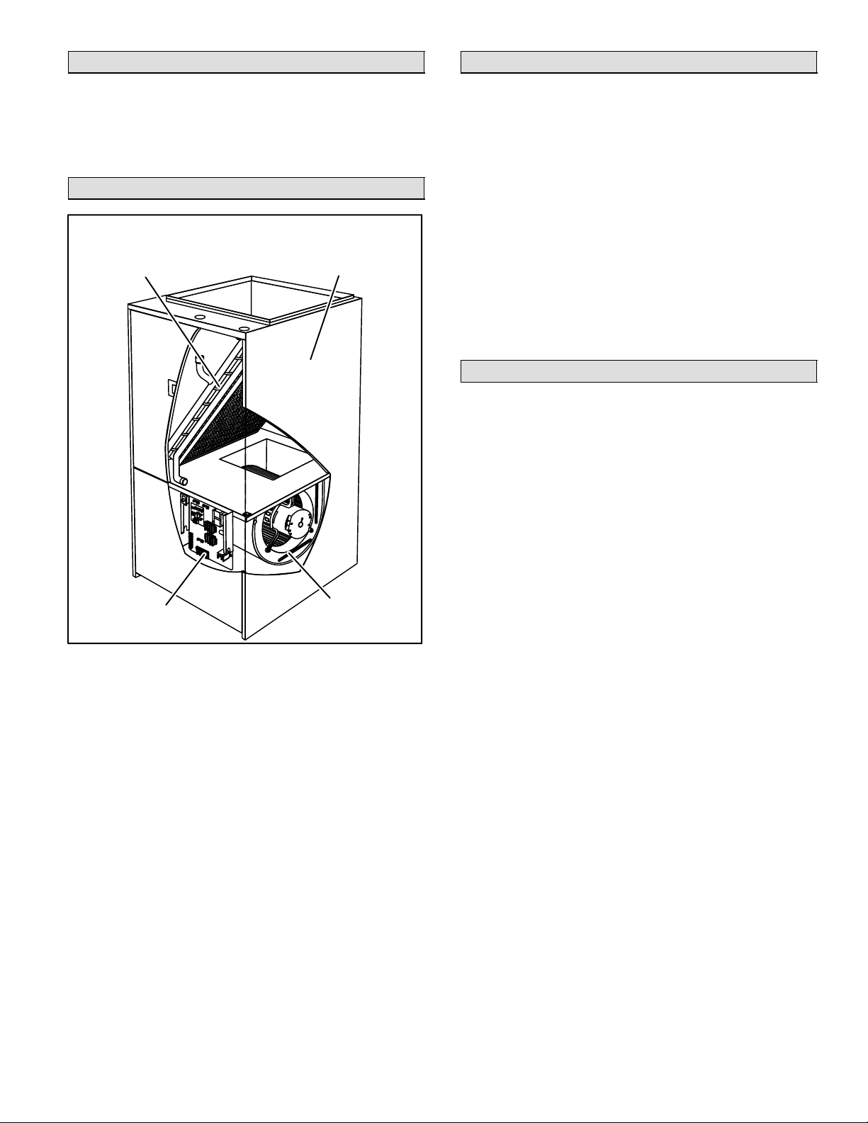
CBWMV Unit Parts Arrangement
CBWMV Unit
HOT WATER
COPPER
TUBE COIL
INSULATED
STEEL
CABINET
Blower
The CBWMV is equipped with a variable speed motor that
provides separate cooling and heating CFM selections
and low continuous fan speeds.
Hot Water Coil
The copper tube coil is equipped with aluminum fins which
provide excellent heat transfer. Manual air bleed ports are
located in the copper tubing to release trapped air in the
water circuit in all unit configurations.
Blower Control
The control provides a fixed blower delay of 45 seconds
ON / 30 seconds OFF on a W call.
Thermostat and accessory connections are made to the
terminal strips in the control box.
CBWMV Unit Optional Accessories
Accessory Circulators (53J76, 99K69)
An accessory circulator should be used in long line applications. Two circulators are available with either 9 gallons per minute (99K69) or 14 gpm (53J76) flow rate. Both
units have 7/8" soldering joints (inlet and outlet) . See piping section for more information.
CBWMV
CONTROL BOX
Figure 1
SUPPLY AIR
BLOWER
Downflow Base (68M03)
A downflow base kit is available for downflow applications
without add−on cooling coils. The base provides clearance
for routing the CBWMV unit’s inlet and outlet water lines.
NOTE − Downflow applications with an add−on cooling coil
require field−fabricated transitions to provide adequate
clearance for servicing/removing the cooling coil without
cutting the water lines.
Page 3
CBWMV SERIES
Requirements
WARNING
Improper installation, adjustment, alteration, service or maintenance can cause personal injury, loss
of life, or damage to property.
Installation and service must be performed by a
qualified installer or service agency.
Installation of Lennox CBWMV unit must conform with local building codes. Refer to the electrical section (Page 8)
for US and Canadian electrical regulations.
When paired with a water heating device, refer to local
building codes for special considerations. Refer to water
heating device for agency and service clearances. Clearances to combustibles for the CBWMV unit only is zero
inches on all sides. Table 1 lists recommended service
clearances.
Table 1
CBWMV Unit Service Clearances
Clearances Location Inches (mm)
Recommended
Service Access
NOTE − Service access clearance must be maintained.
Accessibility and service clearances must take precedence over fire protection clearances.
For installation in a residential garage, unit must be located or protected to avoid physical damage by vehicles.
The CBWMV unit must be installed so that its electrical
components are protected from water.
When the CBWMV unit is used with an air conditioner, the
air handler shall be installed on the upstream side of the
cooling evaporator coil to avoid freeze−up of water system
and condensation. With a parallel flow arrangement, a
damper (or other means to control the flow of air) must adequately prevent chilled air from entering the air handler. If
the damper is manually operated, it must be equipped to
prevent operation of either the heating or the cooling unit,
unless it is in the full HEAT or COOL setting.
NOTE − CBWMV series units must not be used in or for the
following applications:
S construction heater − during any phase of construction
S unit heater
S mobile home heater
S potable water applications
Front Access
Panel
30 (762)
Application
The CBWMV unit is designed for use in non−potable water
boiler systems. The water heating device must be adequate to provide enough heat according to the Engineering
Handbook specifications. The water heating device must
provide a minimum of 6 gallons/minute for small units
(CBWMV−040, −070) and 9 gallons/minute for large units
(CBWMV−090, −100, −120).
Installation − Setting Equipment
WARNING
This product contains fiberglass wool.
Disturbing the insulation during installation, maintenance, or repair will expose you to fiberglass wool
dust. Breathing this may cause lung cancer. (Fiberglass wool is known to the State of California to
cause cancer.)
Fiberglass wool may also cause respiratory, skin,
and eye irritation.
To reduce exposure to this substance or for further
information, consult material safety data sheets
available from address shown below, or contact
your supervisor.
Lennox Industries Inc.
P.O. Box 799900
Dallas, TX 75379−9900
The boiler installation must conform to the requirements of
the authority having jurisdiction or, in the absence of such
requirements, to the latest revision of the National Fuel
Gas Code, ANSI Z223. (Available from the American Gas
Association, 8501 E. Pleasant Valley Road, Cleveland,
OH 44134). Reference should also be made to local gas
utility regulations and other codes in effect in the same
area in which the installation is to be made. When installed
in Canada: The latest revision of the CAN1/CSA−B149.1
and/or B149.2 Installation Codes for Gas-Burning Equipment and/or local codes.
Determine the CBWMV unit installation location and position units so that door panels are accessible. Keep in mind
routing of the water and plumbing lines and electrical connections.
The CBWMV unit is multi−positional. No adjustment is necessary to apply unit for upflow or horizontal discharge. A
downflow base is available and provides clearance for
routing the inlet/outlet water lines when the CBWMV unit is
applied without an add−on cooling coil. Downflow applica-
505047 09/06
Page 4
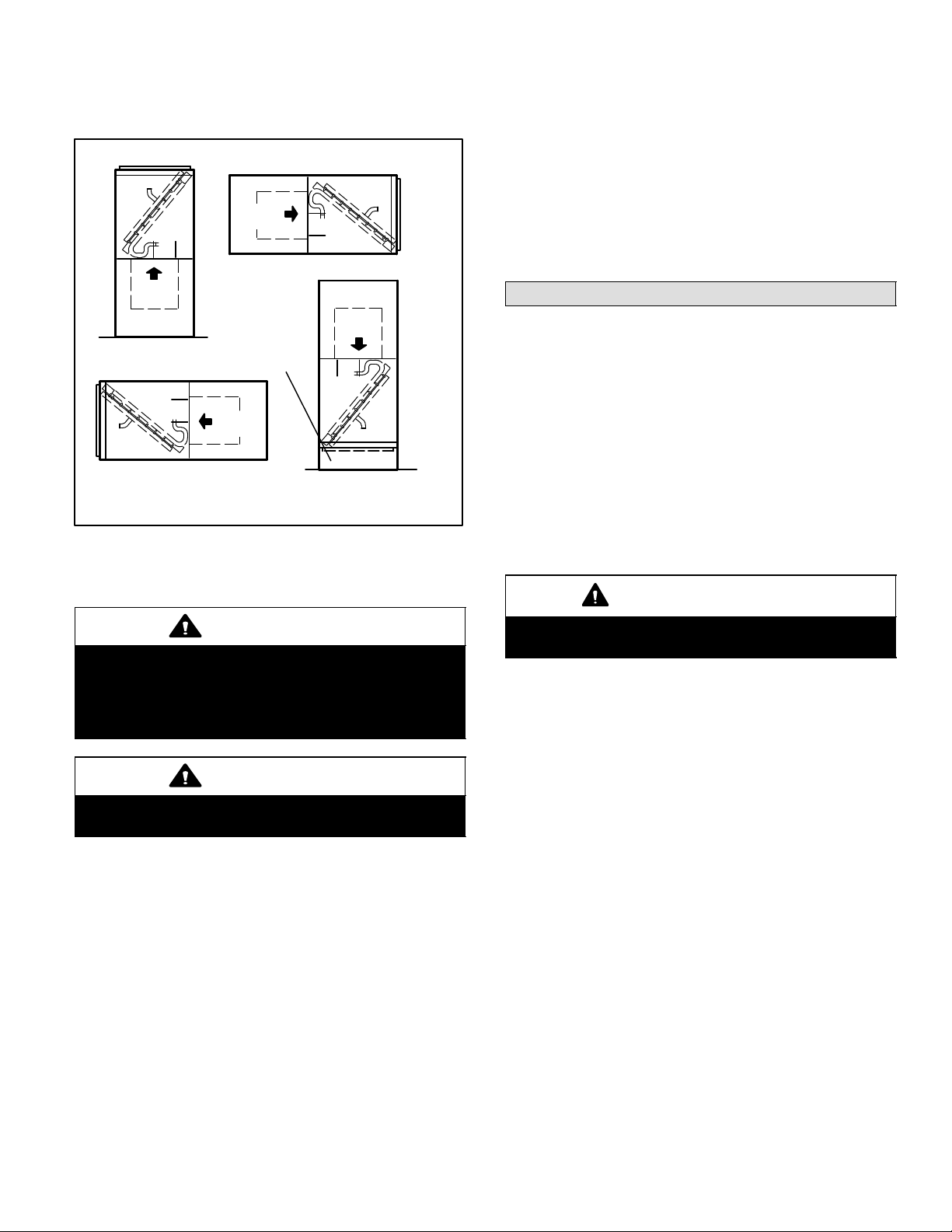
tions with add−on cooling coils require field−fabricated transitions that provide at least 6 inches of clearance for the
CBWMV unit’s inlet/outlet water lines. See figure 2 for examples.
CBWMV Multi−Positional Unit
AIR
FLOW
RIGHT HAND DISCHARGE*
AIR
FLOW
AIR
FLOW
UPFLOW
DOWNFLOW BASE
AIR
FLOW
Either suspend the unit from the roof rafters or floor joists
or mount on a platform. The CBWMV unit must be level
and well supported.
NOTE − 1/2 hp and 1 hp blower motors are equipped with
three flexible legs and one rigid leg. The rigid leg is
equipped with a shipping bolt and a flat white plastic washer (rather than the rubber mounting grommet used with a
flexible mounting leg). The bolt and washer must be re-
moved before the air handler is placed into operation.
After the bolt and washer have been removed, the rigid leg
will not touch the blower housing.
Duct System
Use industry-approved standards (such as those published by Air Conditioning Contractors of America or American Society of Heating, Refrigerating and Air Conditioning
Engineers) to size and install the supply and return air duct
system. This will result in a quiet and low-static system that
has uniform air distribution.
LEFT HAND DISCHARGE*
DOWNFLOW
* CBWMV units must not be installed horizontally on the front or
back of the unit.
Figure 2
Units may be horizontally installed in either attic or crawl
space.
CAUTION
CBWMV series units are shipped with an antifreeze
thermostat to prevent the water coil from freezing.
The freezestat is installed at the factory but must be
field wired (see figures 12 and 13). Do not bypass
this feature when you install or run the unit.
CAUTION
Use a drain pan for installations over finished living
areas.
NOTE − Do not operate the air handler with an external
static pressure that exceeds 0.8 inches w.c. Higher external static pressures may cause erratic operation.
Return Air Plenum
IMPORTANT
Return air must not be drawn from a room where any
fossil fuel appliance (ie., a water heater) is installed.
When return air is drawn from a room, a negative pressure is created in the room. If a fossil fuel appliance is operating in a room with negative pressure, the flue products can be pulled back down the vent pipe and into the
room. This reverse flow of the flue gas may result in incomplete combustion and the formation of carbon monoxide gas. This toxic gas might then be distributed
throughout the house by the air handler duct system.
Page 5
CBWMV SERIES
Return Air Opening Guidelines
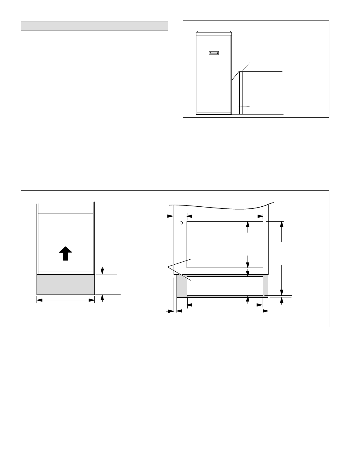
Side Return Air With Transition And Filter
NOTE − Do not bring in air from the back of the unit. Return
air can be brought in from the sides or bottom only.
Bottom Return
If the air handler is installed on a platform with bottom return, make an airtight seal between the bottom of the air
handler and the platform to ensure that the air handler operates properly and safely. Use aluminum tape or mastic
between the plenum and the air handler cabinet to ensure
a tight seal. The air handler is equipped with a removable
bottom panel to facilitate installation.
Side Return
For side return air applications, cut the air handler cabinet
at the maximum return air dimensions shown on page 2.
See figure 3 for a typical side inlet arrangement with a transition and filter.
NOTE − Single side inlet applications result in approximately a 4 percent reduction of CFM on B−size units and
approximately a 5 percent reduction of CFM on C−size
units:
Optional Return Air Base and Unit Dimensions − Inches (mm)
20" X 25" X 1"
(508MM X 635MM X 25MM)
CLEANABLE FILTER
RETURN AIR
PLENUM
TRANSITION
Figure 3
Return Air Base
For return air with the optional return air base (RAB), see
figure 4 (and refer to installation instructions provided with
Return Air Base kit).
*NOTE − Both unit and return air base openings must be
connected to and entirely covered by a single plenum or
IAQ accessory opening. Optional side return air filter kits
cannot be used with RAB Return Air Base.
4
(102)
*23 (584) Overall (Max.)
AIR FLOW
RETURN
AIR BASE
17 (432) RAB−B (98M60)
21 (533) RAB−C (98M58)
FRONT VIEW
NOTE − IN SIDE RETURN
APPLICATIONS, THE RAB
IS REQUIRED FOR 100%
CFM CAPACITY.
Side Return
Air Openings
(Either Side)
7−1/4
(184)
7/8 (22)
Figure 4
*Unit
Opening
*Base
Opening
27−5/8 (702)
SIDE VIEW
23 (584)
*Minimum
11 (279)
*Maximum
14 (356)
5−5/8
(143)
*Height varies
with plenum or
IAQ accessory
height.
3/4
(19)
505047 09/06
Page 6
 Loading...