

Page 1
Default Login Details
User’s Guide
WAP6906
Tri-band WiFi Repeater
Web Address http://zyxelsetup
(Windows)
http://zyxelsetup.local
(Mac)
LAN IP Address http://192.168.1.5
Password (See the device label)
Version 1.0 Edition 1, 02/2018
Copyright © 2018 Zyxel Communications Corporation
Page 2

IMPORTANT!
READ CAREFULLY BEFORE USE.
KEEP THIS GUIDE FOR FUTURE REFERENCE.
Screenshots and graphics in this book may differ slightly from what you see due to differences in release
versions or your computer operating system. Every effort has been made to ensure that the information
in this manual is accurate.
Related Documentation
•Quick Start Guide
The Quick Start Guide shows how to connect the managed device.
•More Information
Go to support.zyxel.com to find other information on the WAP6906
.
WAP6906 User’s Guide
2
Page 3
Document Conventions
Warnings and Notes
These are how warnings and notes are shown in this guide.
Warnings tell you about things that could harm you or your device.
Note: Notes tell you other important information (for example, other things you may need to
configure or helpful tips) or recommendations.
Syntax Conventions
• The WAP6906 may be referred to as the “WAP6906” in this guide.
• Product labels, screen names, field labels and field choices are all in bold font.
• A right angle bracket ( > ) within a screen name denotes a mouse click. For example, Configuration >
Wireless Network 2.4G > MAC Filter means you first click Configuration in the navigation panel, then
the Wireless Network 2.4G sub menu and finally the MAC Filter tab to get to that screen.
Icons Used in Figures
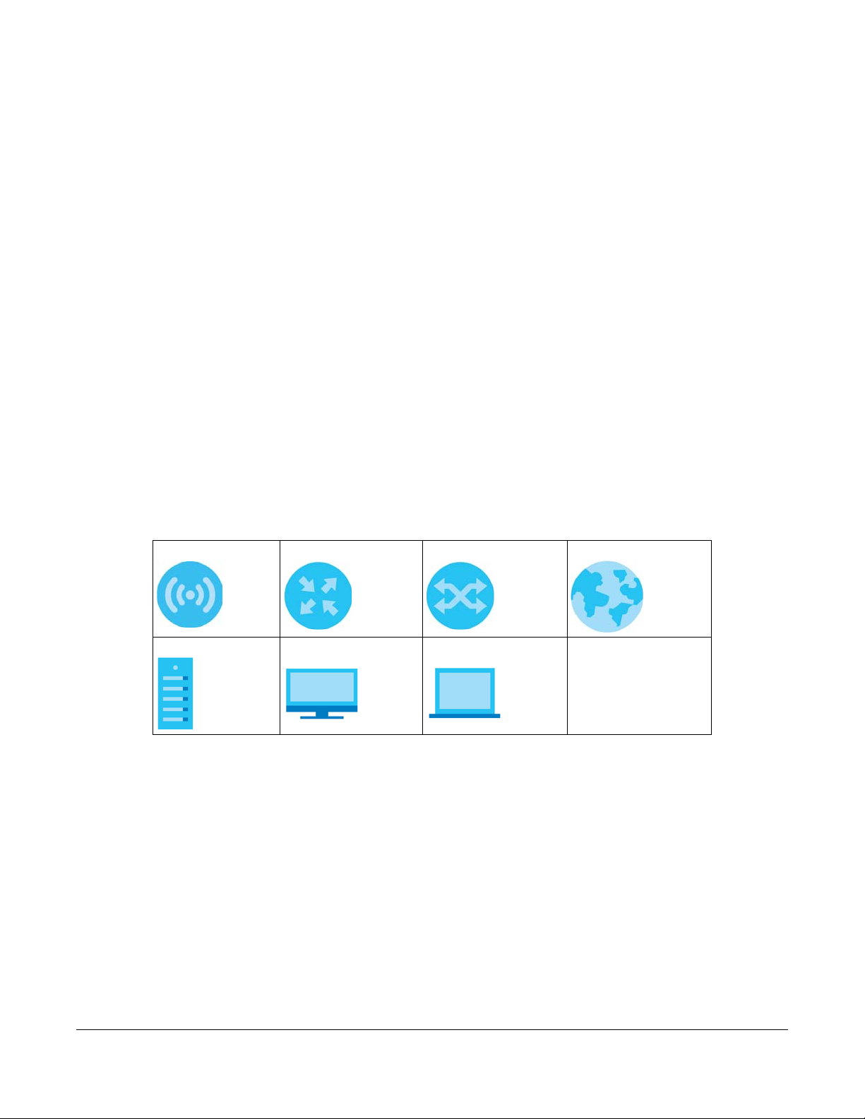
Figures in this guide may use the following generic icons. The WAP6906 icon is not an exact
representation of your device.
WAP6906 Router Switch Internet
Server Desktop Laptop
WAP6906 User’s Guide
3
Page 4

Contents Overview
Contents Overview
User’s Guide ........................................................................................................................................9
Introduction ........................................................................................................................................... 10
The Web Configurator ......................................................................................................................... 15
Easy Mode ............................................................................................................................................. 22
Expert Mode .......................................................................................................................................... 25
Tutorials .................................................................................................................................................. 30
Technical Reference ........................................................................................................................36
Monitor ................................................................................................................................................... 37
Network ................................................................................................................................................. 44
Wireless LAN .......................................................................................................................................... 47
AP Connection ..................................................................................................................................... 55
Maintenance ........................................................................................................................................ 59
Troubleshooting .................................................................................................................................... 66
WAP6906 User’s Guide
4
Page 5

Table of Contents
Table of Contents
Document Conventions .................................................................. ....................................................3
Contents Overview .............................................................................................................................4
Table of Contents.................................................................................................................................5
Part I: User’s Guide............................................................................................ 9
Chapter 1
Introduction ........................................................................................................................................10
1.1 Overview ......................................................................................................................................... 10
1.2 Ways to Manage the WAP6906 .................................................................................................... 10
1.3 Securing the WAP6906 ................................................................................................................... 11
1.4 Front Panel and LEDs ...................................................................................................................... 11
1.5 Rear Panel ....................................................................................................................................... 12
1.6 The WPS Button ............................................................................................................................... 13
1.6.1 Using the WPS Button ............................................................................................................ 14
1.7 The RESET Button ............................................................................................................................. 14
1.7.1 Using the RESET Button .......................................................................................................... 14
Chapter 2
The Web Configurator........................................................................................................................15
2.1 Overview ......................................................................................................................................... 15
2.2 Accessing the Web Configurator ................................................................................................. 15
2.3 Web Configuration Modes ............................................................................................................ 16
2.4 Preparing your Computer to Access the Web Configurator .................................................... 17
2.4.1 Static IP Configuration in Microsoft Windows .................................................................... 17
2.4.2 Static IP Configuration in MAC OS X ................................................................................... 19
Chapter 3
Easy Mode..........................................................................................................................................22
3.1 Overview ......................................................................................................................................... 22
3.1.1 What You Can Do ................................................................................................................. 22
3.2 Navigation Panel ............................................................................................................................ 22
3.3 Network Map .................................................................................................................................. 23
3.4 Status Screen in Easy Mode .......................................................................................................... 24
Chapter 4
Expert Mode.......................................................................................................................................25
WAP6906 User’s Guide
5
Page 6

Table of Contents
4.1 Overview ......................................................................................................................................... 25
4.2 Web Configurator Layout in Expert Mode .................................................................................. 25
4.3 Status Screen ................................................................................................................................... 26
4.3.1 Navigation Panel .................................................................................................................. 27
Chapter 5
Tutorials...............................................................................................................................................30
5.1 Overview ......................................................................................................................................... 30
5.2 Connecting to the Internet from an Access Point ..................................................................... 30
5.3 Connecting to the WAP6906’s Wireless Network Using WPS ..................................................... 30
5.3.1 Push Button Configuration (PBC) ........................................................................................ 31
5.3.2 PIN Configuration .................................................................................................................. 32
5.4 Connecting the WAP6906 to an AP ............................................................................................. 33
5.4.1 Selecting an AP from an Automatically Detected List ..................................................... 34
5.4.2 Selecting an AP by Manually Entering Security Information ............................................ 34
Part II: Technical Reference........................................................................... 36
Chapter 6
Monitor................................................................................................................................................37
6.1 Overview ......................................................................................................................................... 37
6.2 What You Can Do .......................................................................................................................... 37
6.3 Log .................................................................................................................................................... 37
6.4 Wireless Monitor .......................................................................................................................... 38
6.5 MBSS Monitor ................................................................................................................................... 41
6.6 Multicast Monitor ............................................................................................................................ 43
Chapter 7
Network...............................................................................................................................................44
7.1 Overview ......................................................................................................................................... 44
7.2 What You Can Do .......................................................................................................................... 44
7.3 What You Need To Know .............................................................................................................. 44
7.4 Networking Screen ......................................................................................................................... 45
Chapter 8
Wireless LAN .......................................................................................................................................47
8.1 Overview ......................................................................................................................................... 47
8.2 What You Can Do .......................................................................................................................... 47
8.3 What You Should Know ................................................................................................................. 48
8.3.1 Wireless Security Overview ................................................................................................... 48
8.3.2 MAC Address Filter ................................................................................................................ 48
WAP6906 User’s Guide
6
Page 7

Table of Contents
8.3.3 Encryption .............................................................................................................................. 49
8.3.4 WPS ......................................................................................................................................... 49
8.3.5 WDS ......................................................................................................................................... 49
8.4 Basic Wireless Network Screen ..................................................................................................... 49
8.5 Advanced Wireless Network Screen ............................................................................................ 51
8.6 WPS Screen ..................................................................................................................................... 51
8.7 MAC Filter ........................................................................................................................................ 52
8.8 MBSS Screen .................................................................................................................................... 53
Chapter 9
AP Connection...................................................................................................................................55
9.1 Overview ......................................................................................................................................... 55
9.2 What You Can Do .......................................................................................................................... 55
9.3 Station Screen ................................................................................................................................. 55
9.4 AP List Screen .................................................................................................................................. 56
9.5 WPS Screen ..................................................................................................................................... 57
Chapter 10
Maintenance......................................................................................................................................59
10.1 Overview ....................................................................................................................................... 59
10.2 What You Can Do ........................................................................................................................ 59
10.3 Password Screen .......................................................................................................................... 59
10.4 Time Screen ................................................................................................................................... 60
10.5 Firmware Upgrade Screen .......................................................................................................... 61
10.6 Telnet Screen ................................................................................................................................ 62
10.7 Restore Screen .............................................................................................................................. 63
10.7.1 Backup Configuration ........................................................................................................ 63
10.7.2 Restore Configuration ........................................................................................................ 64
10.7.3 Back to Factory Defaults .................................................................................................... 64
10.7.4 Restore but retain IP settings .............................................................................................. 64
10.8 Restart Screen ............................................................................................................................... 65
Chapter 11
Troubleshooting..................................................................................................................................66
11.1 Power, Hardware Connections, and LEDs ................................................................................. 66
11.2 WAP6906 Access and Login ........................................................................................................ 67
11.3 Internet Access ............................................................................................................................. 68
11.4 Resetting the WAP6906 to Its Factory Defaults ......................................................................... 69
11.5 Wireless Problems .......................................................................................................................... 69
Appendix A Wireless LANs ................................................................................................................ 70
Appendix B Customer Support ........................................................................................................ 83
WAP6906 User’s Guide
7
Page 8

Table of Contents
Appendix C Legal Information ........................................................................................................ 89
Index...................................................................................................................................................97
WAP6906 User’s Guide
8
Page 9

PART I
User’s Guide
9
Page 10
1.1 Overview
WAP6906
AP
The WAP6906 extends the range of your existing wired network without additional wiring, providing easy
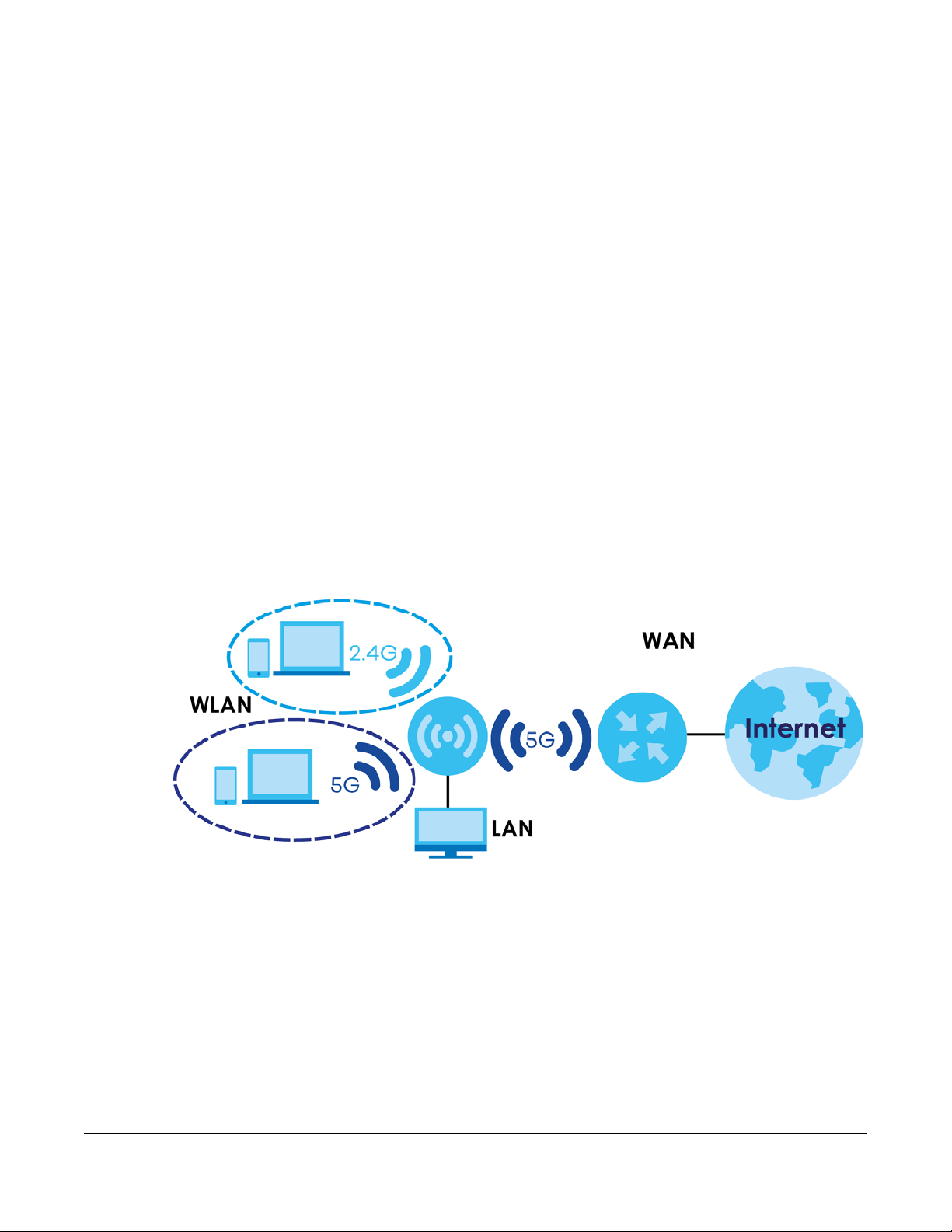
network access to mobile users. The WAP6906 is a tri-band WiFi repeater, which means it delivers wireless
speed through its dedicated 5GHz connection (between WAP6906 and AP), and broadcasts to its
wireless clients with 2.4GHz and 5GHz WiFi network. You can set up the WAP6906 with other IEEE 802.11a/
b/g/n/ac/an compatible devices.
Your WAP6906 can act as an access point and wireless client at the same time. The WAP6906 can
connect to an existing network through another access point and also lets wireless clients connect to
the network through it. This helps you expand wireless coverage when you have an access point or
wireless router already in your network. After the WAP6906 and the access point connect, the WAP6906
acquires its IP address from the access point. The clients of the WAP6906 can now surf the Internet.
In the example below, the WAP6906 has two clients in its 2.4GHz network, two clients in its 5GHz network,
and one client via Ethernet that want to connect to the Internet. The WAP6906 wirelessly connects to
the available access point (AP).
CHAPTER 1
Introduction
1.2 Ways to Manage the WAP6906
Use any of the following methods to manage the WAP6906.
• Web Configurator. This is recommended for everyday management of the WAP6906 using a
(supported) web browser.
• WPS (WiFi Protected Security) button. Use the WPS button or the WPS section of the Web Configurator
to set up a wireless network with your WAP6906.
WAP6906 User’s Guide
10
Page 11
Chapter 1 Introduction
LED
1.3 Securing the WAP6906
Do the following things regularly to make the WAP6906 more secure and to manage the WAP6906 more
effectively.
• Change the password. Use a password that’s not easy to guess and that consists of different types of
characters, such as numbers and letters.
• Write down the password and put it in a safe place.
• Back up the configuration (and make sure you know how to restore it). Restoring an earlier working
configuration may be useful if the device becomes unstable or even crashes. If you forget your
password, you will have to reset the WAP6906 to its factory default settings. If you backed up an
earlier configuration file, you would not have to totally re-configure the WAP6906. You could simply
restore your last configuration.
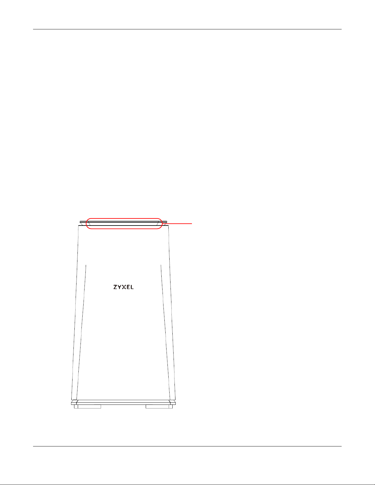
1.4 Front Panel and LEDs
The following figure is the front panel of the WAP6906. Use the LEDs to determine if the WAP6906 is
behaving normally or if there are some problems on your network.
Figure 1 Front Panel
WAP6906 User’s Guide
11
Page 12
Chapter 1 Introduction
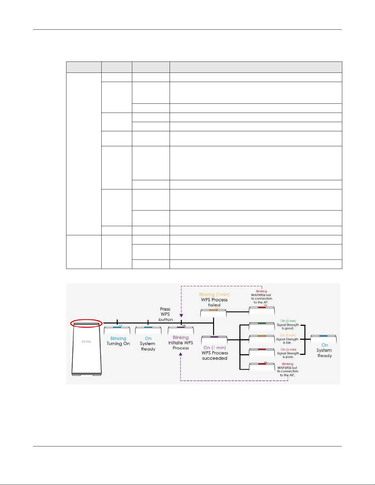
The following table describes the LED behavior.
Table 1 Front Panel LEDs
LED COLOR STATUS DESCRIPTION
Top LED White Blinking The WAP6906 is upgrading its firmware, rebooting or resetting.
Blue On The WAP6906 is receiving power and functioning properly, but the
Blinking The WAP6906 is turning on.
Purple On The LED is on for 1 minute indicating the WPS process was successful.
Blinking The WAP6906 is negotiating a WPS connection with a wireless client.
Green On The LED is on for 5 minutes indicating the wireless router or AP and
Amber On The LED is on for 5 minutes indicating the wireless router or AP and
Blinking The LED is blinking for 1 minute indicating the WPS process failed.
Red On The LED is on for 5 minutes indicating the wireless router or AP and
Blinking The WAP6906 lost its wireless connection to the AP. Find a new location
Off The WAP6906 is not receiving power.
LAN Port LED Green On The WAP6906 has a successful 10/100/1000 Mbps Ethernet connection.
Blinking The WAP6906 is sending or receiving packets to/from an Ethernet
Off There is no connection on this port.
wireless interface of the WAP6906 is not up or it has been up for more
than 5 minutes.
WAP6906 are connected, and the received signal strength is good.
WAP6906 are connected, and the received signal strength is too good.
This may cause interference with the wireless router or AP’s signal.
Move the WAP6906 away from the wireless router or AP for a larger
range.
WAP6906 are connected, and the received signal strength is poor.
Move the WAP6906 closer to your wireless router or AP.
for the WAP6906 or press the WPS button to restart the WPS process.
network on this port.
The timeline below helps you understand more about the WAP6906 LED behavior.
1.5 Rear Panel
The following figure is the rear panel of the WAP6906.
WAP6906 User’s Guide
12
Page 13
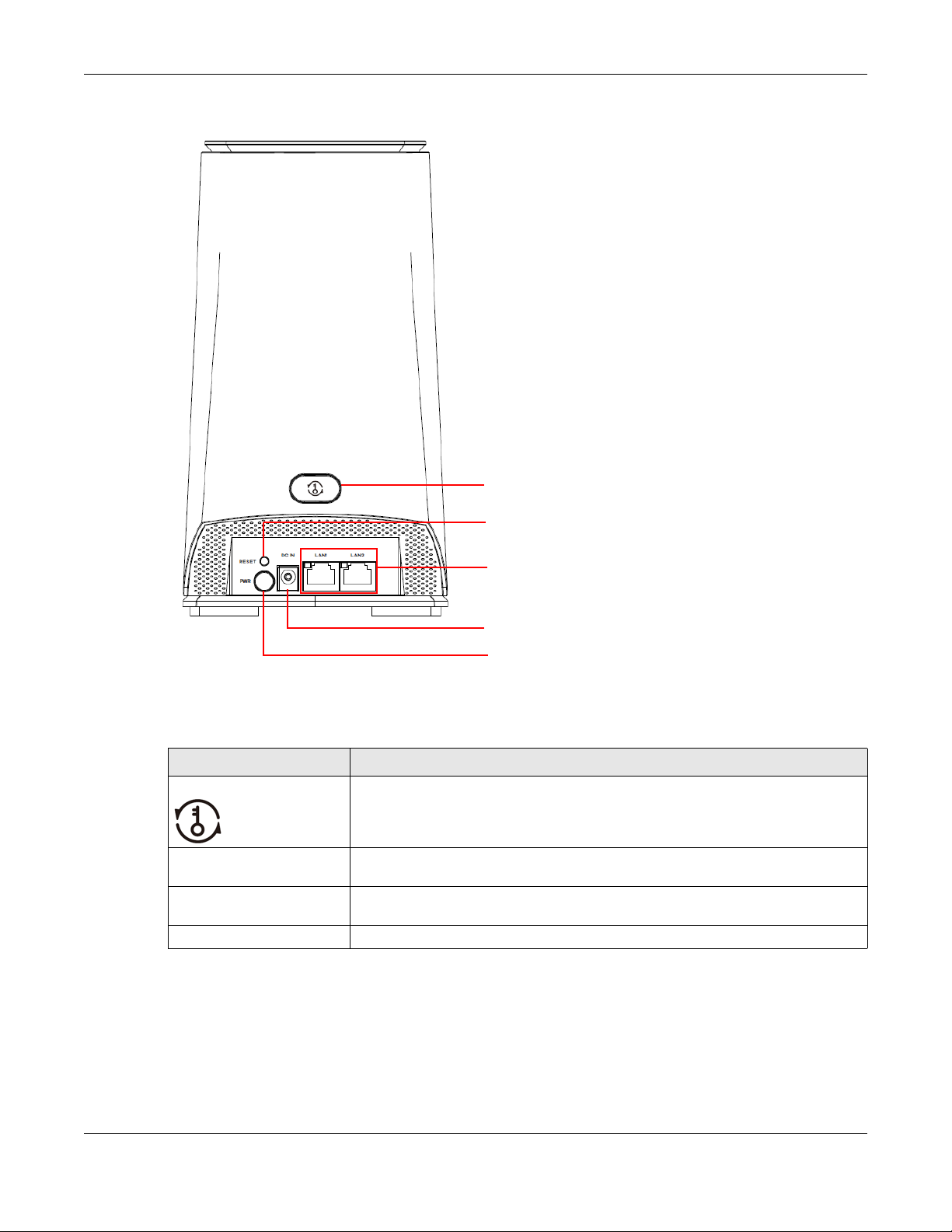
Figure 2 Rear Panel
WPS Button
Reset Button
LAN LEDs and
LAN Ports
Power Cable
Power Button
Chapter 1 Introduction
The following table describes the items on the rear panel.
Table 2 Rear Panel Ports
LABEL DESCRIPTION
WPS Press the WPS button to establish a secure wireless connection using WiFi Protected
RESET Press the button to return the WAP6906 to the factory default settings. See Section
PWR / DC IN Connect the power cable to the DC IN and press the power button to start the
LAN1~LAN2 Connect computers or other Ethernet devices to Ethernet ports for Internet access.
1.6 The WPS Button
Your WAP6906 supports WiFi Protected Setup (WPS), which is an easy way to set up a secure wireless
network. WPS is an industry standard specification, defined by the WiFi Alliance.
Setup (WPS). See Section 1.6 on page 13.
1.7 on page 14.
device.
WAP6906 User’s Guide
13
Page 14

WPS allows you to quickly set up a wireless network with strong security, without having to configure
security settings manually. Each WPS connection works between two devices. Both devices must
support WPS (check each device’s documentation to make sure).
Depending on the devices you have, you can either press a button (recommended) on the device
itself, or in its configuration utility or enter a PIN (a unique Personal Identification Number that allows one
device to authenticate the other) in each of the two devices. When WPS is activated on a device, it has
two minutes to find another device that also has WPS activated. Then, the two devices connect and set
up a secure network by themselves.
The WPS button is located at the back panel of the WAP6906.
1.6.1 Using the WPS Button
1 Make sure the power LED is on (not blinking).
2 Uplink: Press the WPS button once. Press the WPS button on a WPS-aware AP or wireless router within
range of the WAP6906.
Downlink: Press the WPS button twice within three seconds. Press the WPS button on a WPS-aware client
within range of the WAP6906.
Chapter 1 Introduction
Note: You must activate WPS in the WAP6906 and in another wireless device within two
minutes of each other.
Note: With WPS, wireless clients can only connect to the 5GHz or 2.4GHz wireless network using
the first 5GHz or 2.4GHz SSID on the WAP6906.
For more information on using WPS, see Section 5.3 on page 30.
1.7 The RESET Button
If you forget your password or IP address, or you cannot access the Web Configurator, you will need to
use the RESET button at the back of the WAP6906 to reload the factory-default configuration file. This
means that you will lose all configurations that you had previously saved, the password will be reset to
the default key on the device label. The WAP6906 will be reset to obtain an IP address from a DHCP
server.
1.7.1 Using the RESET Button
1 Make sure the power LED is on (not blinking).
2 Press the RESET button for one to five seconds to reboot the WAP6906.
3 Press the RESET button for longer than five seconds to set the WAP6906 back to its factory-default
configurations.
WAP6906 User’s Guide
14
Page 15

2.1 Overview
This chapter describes how to access the WAP6906 Web Configurator and provides an overview of its
screens.
The Web Configurator is an HTML-based management interface that allows easy setup and
management of the WAP6906 via Internet browser. Use Internet Explorer 8.0 and later versions, Mozilla
Firefox, Google Chrome or Safari. The recommended screen resolution is 1024 by 768 pixels.
In order to use the Web Configurator you need to allow:
• Web browser pop-up windows from your device.
• JavaScript (enabled by default).
• Java permissions (enabled by default).
CHAPTER 2
The Web Configurator
Refer to Chapter 11 on page 66 to see how to make sure these functions are allowed in Internet
Explorer.
2.2 Accessing the Web Configurator
1 Make sure your WAP6906 hardware is properly connected and prepare your computer or computer
network to connect to the WAP6906 (refer to the Quick Start Guide).
2 Launch your web browser.
3 Type “http://zyxelsetup” (for Windows) or “http://zyxelsetup.local” (for Mac) as the website address to
access any of the modes.
The WAP6906 is a DHCP client by default. Alternatively, check the connected gateway for the
WAP6906's current IP address. Make sure your computer’s IP address is in the same subnet as the
WAP6906’s IP address. Type “http://(DHCP-assigned IP)” as the web address in your web browser.
If the WAP6906 is not connecting to a router or DHCP server, type the WAP6906’s default static IP
address “http://192.168.1.5”. Your computer must be in the same subnet in order to access this website
address.You must give it a fixed IP address in the range between 192.168.1.11 and 192.168.1.254 (see
Section 2.4 on page 17).
4 Type the password on the device label (default) as the password and click Login.
WAP6906 User’s Guide
15
Page 16

Chapter 2 The Web Configurator
Figure 3 Login Screen
5 You should see a screen asking you to change your password (highly recommended) as shown next.
Type a new password. It must include both alphabet letters and numbers. Click Apply to save your
changes. Click Ignore if you do not want to change the password this time.
Figure 4 Change Password Screen
Right after you log in, the easy mode network map screen is displayed. See Chapter 3 on page 22 for
more information about the easy mode.
2.3 Web Configuration Modes
This refers to the configuration interface of the Web Configurator, which has two modes:
• Easy Mode. The Web Configurator shows this mode by default. Refer to Chapter 3 on page 22 for
more information on the screens in this mode. This shows how the WAP6906’s network is currently laid
out.
• Expert Mode. Advanced users can change to this mode to customize all the functions of the
WAP6906. Click Expert Mode after logging into the Web Configurator. The User’s Guide Chapter 4 on
page 25 through Chapter 10 on page 59 discusses the screens in this mode.
WAP6906 User’s Guide
16
Page 17
Chapter 2 The Web Configurator
2.4 Preparing your Computer to Access the Web Configurator
This section shows you how to assign a static IP address to your computer.
In order to access the web configurator your computer needs to be in the same subnet as the
WAP6906. Below you will find the steps to set a static IP on both Windows 7 (Section 2.4.1 on page 17)
and MAC OS X 10.11(Section 2.4.2 on page 19) operating systems. For other operating systems go to
Appendix C on page 108.
2.4.1 Static IP Configuration in Microsoft Windows
Follow these steps to change your computer’s IP address in Windows 7 operating system.
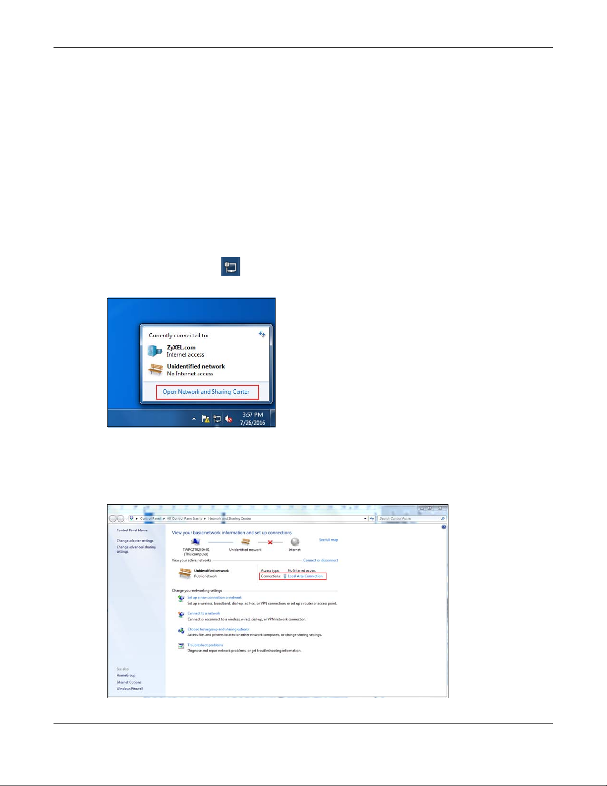
1 Click on the Network Icon located in the System Tray of your Task Bar. After you have clicked the
icon a small message window will appear, select Open Network and Sharing Center.
Note: You can also access the Network and Sharing Center by going to the Control Panel in
the Start Menu and clicking on Network and Sharing Center.
2 Once you have accessed the Network and Sharing Center, click on Local Area Connection to access
the adapter’s settings.
WAP6906 User’s Guide
17
Page 18
Chapter 2 The Web Configurator
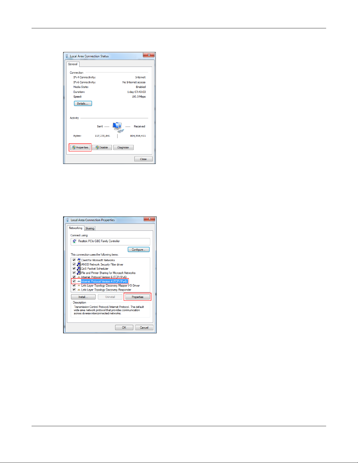
3 After accessing the connection’s general settings, click on the Properties button.
Note: You can also access the adapter’s settings by clicking on Change adapter settings
located on the left side bar. Then right-clicking on the Local Area Connection icon and
selecting Properties.
4 In the connection’s properties select the Internet Protocol Version 4 (TCP/IPv4) item, then click on the
Properties button.
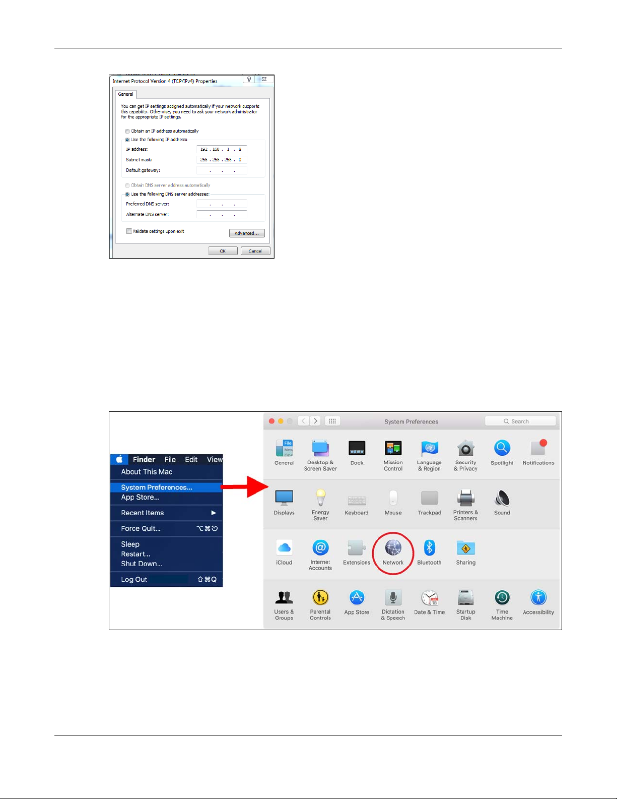
5 Once you have accessed the Internet Protocol Version 4 (TCP/IPv4) properties, click on the Use the
following IP address radio button and type your new IP address. Your computer must be in the same
subnet in order to access this website address.You must give it a fixed IP address in the range between
192.168.1.6 and 192.168.1.254. Then type 255.255.255.0 as your subnet mask, click OK to close the
Internet Protocol Version 4 (TCP/IPv4) Properties window. Then click OK to close the Local Area
Connection
WAP6906 User’s Guide
18
Page 19
Chapter 2 The Web Configurator
Note: After you have configured your WAP6906, you must remember to change your static IP
back to automatic to be able to access the Internet. If you want to change the IP
address to automatic (default) then repeat steps 1 to 4, for step 5 select the Obtain an
IP address automatically radio button, and click OK.
2.4.2 Static IP Configuration in MAC OS X
Follow these steps to change your computer’s IP address in MAC OS X 10.11 operating system.
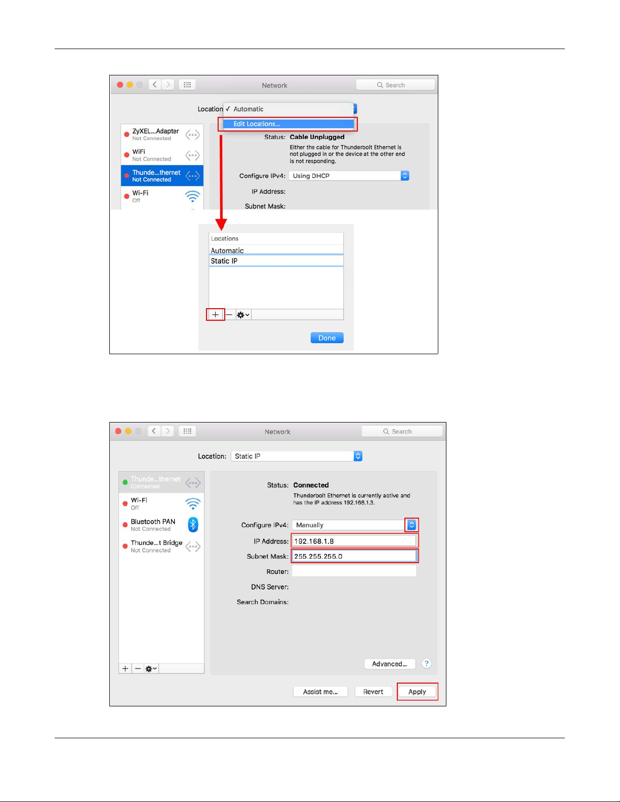
1 Open your System Preferences, then click on Network.
2 Once the Network screen is open, it is recommended you click on Location > Edit Locations to create a
new profile. Use the + button to add a new profile, in this case it is called Static IP. This will easily help you
change from static IP address to automatic.
WAP6906 User’s Guide
19
Page 20
Chapter 2 The Web Configurator
3 After creating your Static IP profile, make sure it is selected, then click on the Configure IPv4 scroll button
and select Manually. Then modify your IP Address, your computer must be in the same subnet in order to
access this website address.You must give it a fixed IP address in the range between 192.168.1.8 and
192.168.1.254. Then type 255.255.255.0 as your subnet mask, and click Apply to save your changes.
WAP6906 User’s Guide
20
Page 21

Chapter 2 The Web Configurator
Note: After you have configured your WAP6906, you must remember to change your static IP
back to obtaining it automatically to be able to access the Internet. If you want to
change the IP address to automatic (default) repeat step 1, then on Location select
Automatic or a different profile you have configured.
WAP6906 User’s Guide
21
Page 22
3.1 Overview
The Web Configurator is set to Easy Mode by default. This mode is useful to users by visualizing their
networks’ layout. You can view details about the devices connected to your WAP6906 and their status.
When you log in to the Web Configurator, the following screen opens.
Figure 5 Easy Mode: Network Map
CHAPTER 3
Easy Mode
3.1.1 What You Can Do
You can do the following in this mode:
• Use the Navigation Panel to opt out of the Easy mode (Section 3.2 on page 22).
• Use the Network Map screen to check if your WAP6906 can ping the gateway and whether it is
connected to the Internet (Section 3.3 on page 23).
• Use the Status screen to view read-only information about the WAP6906, including the WAN IP, MAC
address of the WAP6906 and the software version (Section 3.4 on page 24).
3.2 Navigation Panel
Use this navigation panel to opt out of the Easy mode.
WAP6906 User’s Guide
22
Page 23
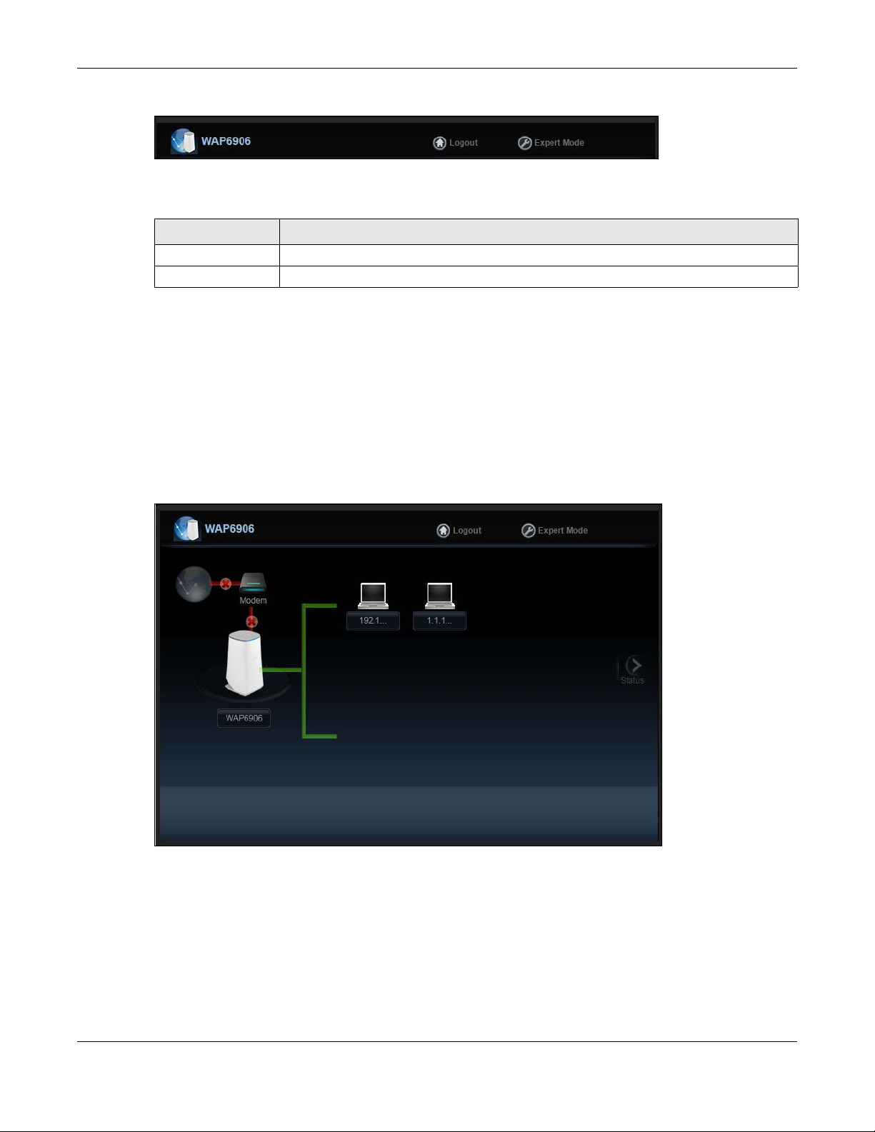
Figure 6 Navigation Panel
The following table describes the labels in this screen.
Table 3 Navigation Panel
LABEL DESCRIPTION
Logout Click this to end the Web Configurator session.
Expert Mode Click this to change to Expert Mode and customize features of the WAP6906.
3.3 Network Map
Note: Don’t worry if the Network Map does not display in your web browser. This feature may
not be supported by your system. You can still configure your WAP6906’s features in the
Expert Mode.
When you log in to the Web Configurator, the Network Map is shown as follows.
Chapter 3 Easy Mode
Figure 7 Network Map
The line connecting the WAP6906 to the gateway becomes green when the WAP6906 is able to ping
the gateway. It becomes red when the ping initiating from the WAP6906 does not get a response from
the gateway. The same rule applies to the line connecting the gateway to the Internet.
You can also view the devices (represented by icons indicating the kind of network device, such as
Android device, iOS device or Windows OS) connected to the WAP6906, including those connecting
wirelessly. Right-click on the Refresh button located on the WAP6906 icon to refresh the network map.
Click on a device’s name to view information about the device.
WAP6906 User’s Guide
23
Page 24
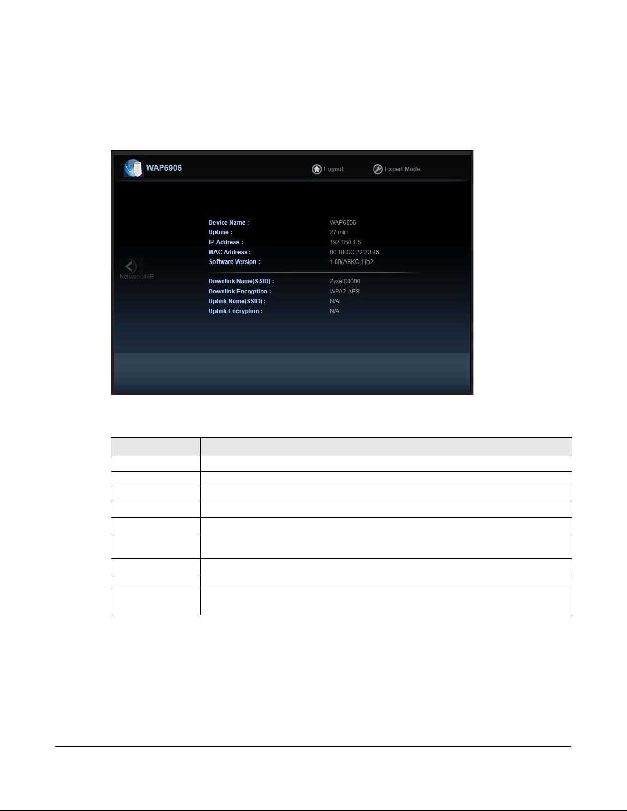
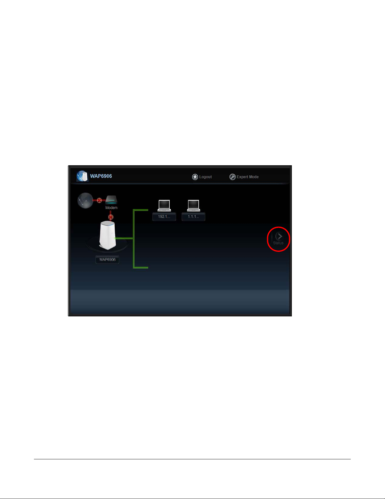
3.4 Status Screen in Easy Mode
In the Network Map, click Status to view read-only information about the WAP6906.
Note: The Status Screen displayed in Easy Mode varies according to the operating mode of
your WAP6906.
Figure 8 Status Screen in Easy Mode
The following table describes the labels in this screen.
Table 4 Status Screen in Easy Mode
LABEL DESCRIPTION
Device Name This is the WAP6906’s model name.
Uptime This displays the time in minutes the WAP6906’s system has been working.
IP Address This shows the LAN port’s IP address.
MAC Address This shows the MAC address of the WAP6906’s LAN port.
Software Version This is the firmware version.
Downlink Name
(SSID)
Downlink Encryption This shows the data encryption method the WAP6906 uses for the wireless connection.
Uplink Name (SSID) This shows the descriptive name of the wireless LAN to which the WAP6906 is connected.
Uplink Encryption This shows the data encryption method the connected access point uses for the wireless
This shows a descriptive name used to identify the WAP6906 in the wireless LAN.
connection.
WAP6906 User’s Guide
24
Page 25
Chapter 4 Expert Mode
B
A
C
CHAPTER 4
Expert Mode
4.1 Overview
Click Expert Mode located in the Easy Mode’s navigation panel.
4.2 Web Configurator Layout in Expert Mode
The Web Configurator in Expert Mode is divided into these parts:
Figure 9 Web Configurator: Expert Mode
• A- Title Bar
• B- Navigation Panel
• C- Main Window
WAP6906 User’s Guide
25
Page 26
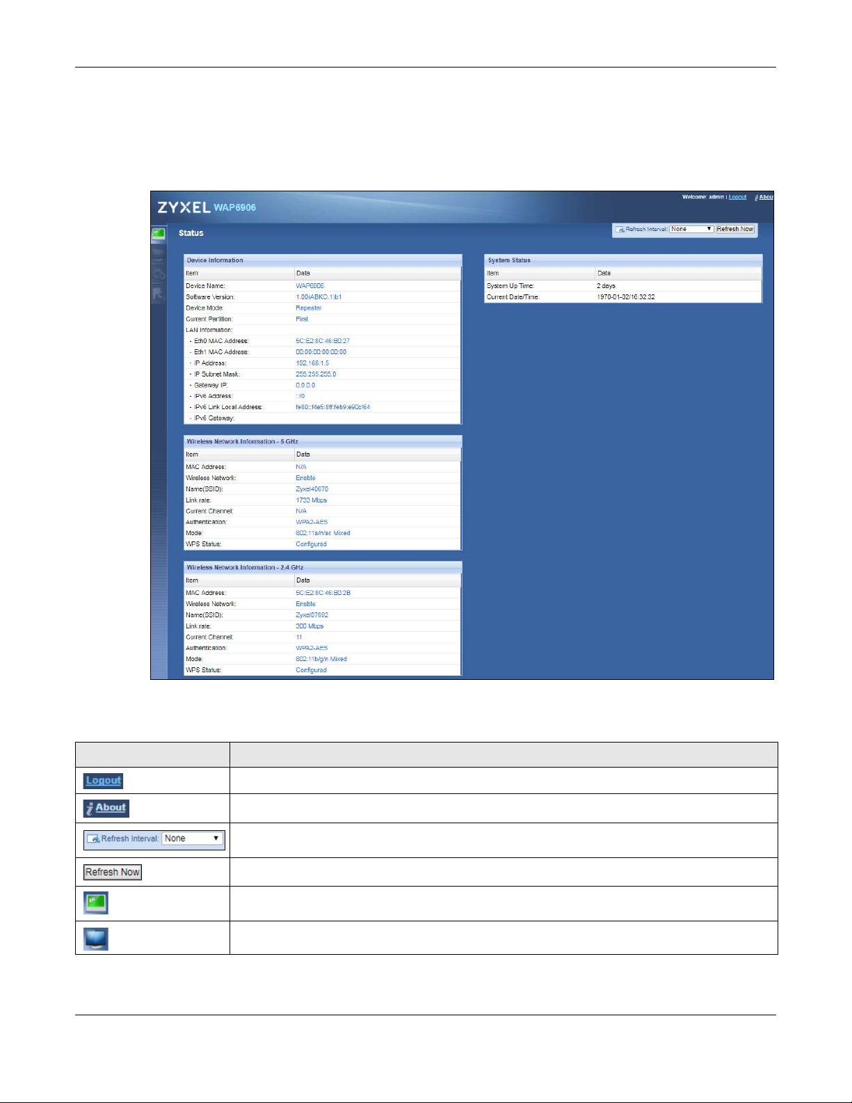
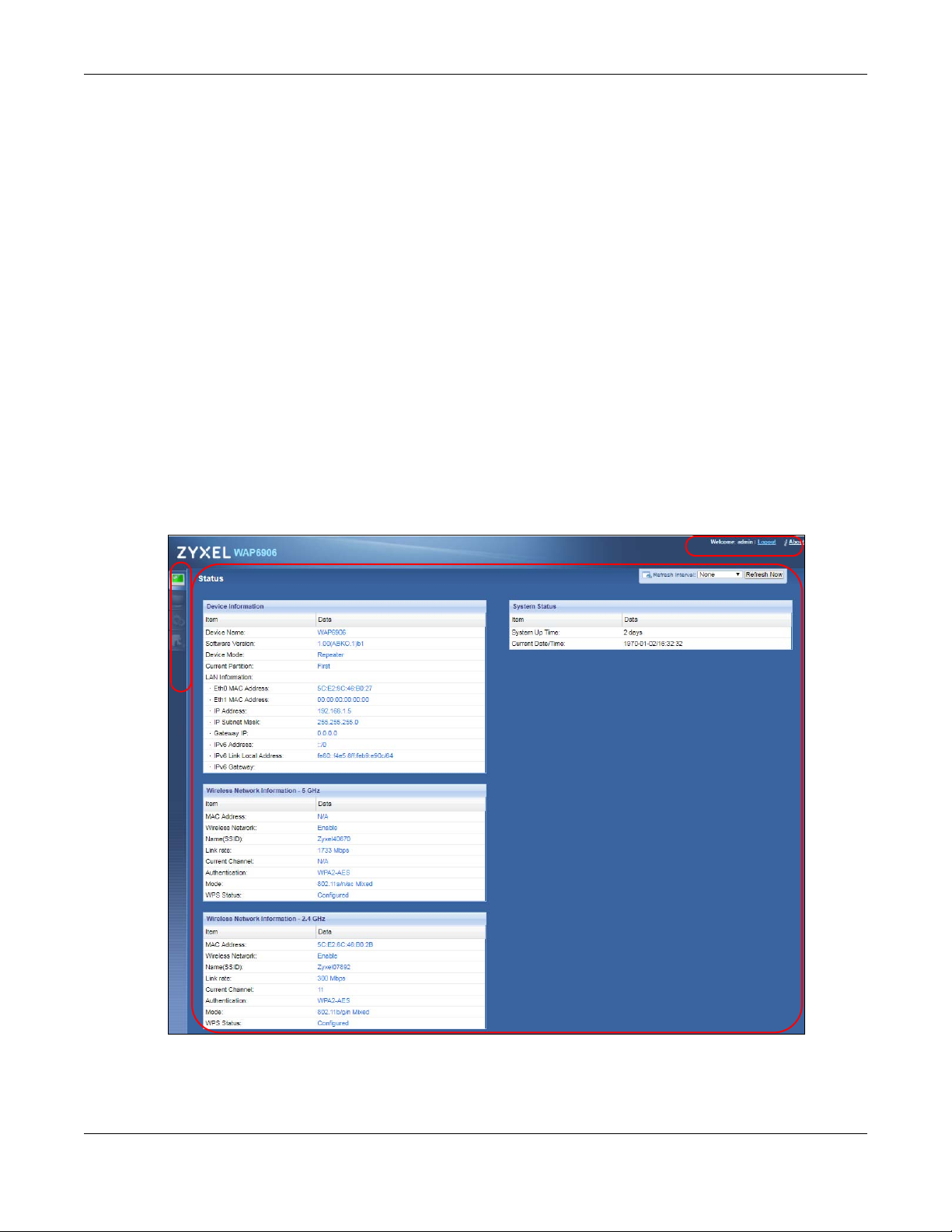
4.3 Status Screen
Click on Status. The screen below shows the Status screen in Expert Mode.
Figure 10 Status Screen
Chapter 4 Expert Mode
The following table describes the icons shown in the Status screen.
Table 5 Status Screen Icon Key
ICON DESCRIPTION
Click this at any time to exit the Web Configurator.
Click this icon to view copyright and a link for related product information.
Select a number of seconds or None from the drop-down list box to refresh all screen statistics
automatically at the end of every time interval or to not refresh the screen statistics.
Click this button to refresh the status screen statistics.
Click this icon to see the Status page. The information in this screen depends on the device mode
you select.
Click this icon to see the Monitor navigation menu.
WAP6906 User’s Guide
26
Page 27
Chapter 4 Expert Mode
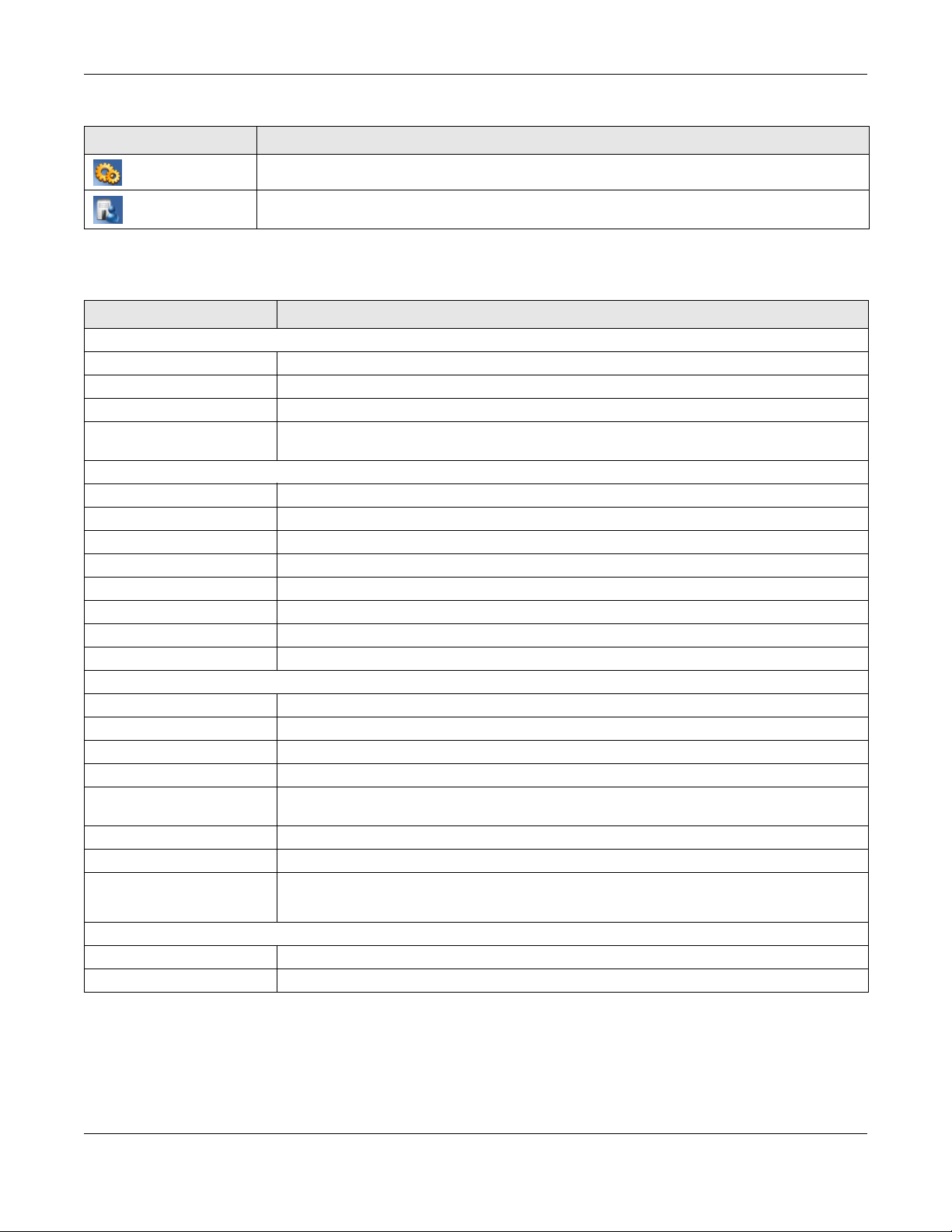
Table 5 Status Screen Icon Key (continued)
ICON DESCRIPTION
Click this icon to see the Configuration navigation menu.
Click this icon to see the Maintenance navigation menu.
The following table describes the labels shown in the Status screen.
Table 6 Status Screen
LABEL DESCRIPTION
Device Information
Device Name This is the WAP6906’s model name.
Software Version This is the firmware version and the date created.
Device Mode This is the device mode to which the WAP6906 is set - Repeater Mode.
Current Partition This shows which partition the WAP6906 uses. The WAP6906 has two partitions and supports dual
image function.
LAN Information
Eth0 MAC Address This shows the MAC Address of the WAP6906’s first Ethernet LAN port.
Eth1 MAC Address This shows the MAC Address of the WAP6906’s second Ethernet LAN port.
IP Address This shows the LAN port’s IP address.
IP Subnet Mask This shows the LAN port’s subnet mask.
Gateway IP This shows the LAN port’s gateway IP address.
IPv6 Address This shows the LAN port’s IPv6 address.
IPv6 Link Local Address This shows the LAN port’s current IPv6 link-local address.
IPv6 Gateway This shows the LAN port’s gateway IPv6 address.
Wireless Network Information - 5 GHz/2.4 GHz
MAC Address This shows the MAC address of the WAP6906’s wireless interface.
Wireless Network This shows if the wireless network is enabled or disabled.
Name (SSID) This shows a descriptive name used to identify the WAP6906 in the wireless LAN.
Link Rate (Mbps) This shows the rate at which data is transferred across the wireless network.
Current Channel This shows the channel number which you select manually or the WAP6906 automatically scans
and selects.
Authentication This shows the data encryption method the WAP6906 uses for the wireless connection.
Mode This shows the wireless standard the WAP6906 uses.
WPS Status This displays Configured when the WPS has been set up.
This displays Unconfigured if the WPS has not been set up.
System Status
System Up Time This is the total time the WAP6906 has been on.
Current Date/Time This field displays your WAP6906’s present date and time.
4.3.1 Navigation Panel
Use the menu in the navigation panel to configure WAP6906 features.
WAP6906 User’s Guide
27
Page 28
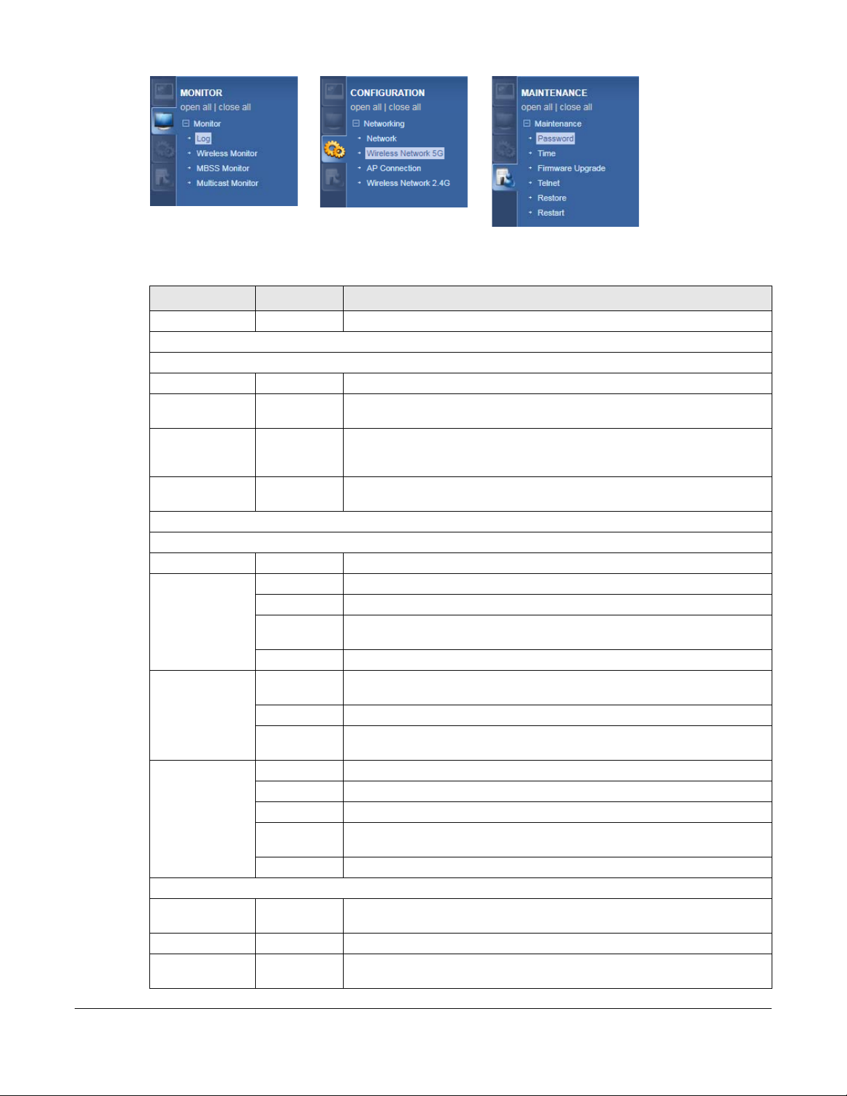
Figure 11 Navigation Panel Menu
The following table describes the sub-menus.
Table 7 Navigation Panel
LINK TAB FUNCTION
Status Status This screen shows the WAP6906’s general device, system status information.
MONITOR
Monitor
Log View Log Use this screen to view the list of activities recorded by your WAP6906.
Wireless
Monitor
MBSS Monitor MBSS Monitor Use this screen to view a summary of the Multiple Basic Server Sets (MBSS)
Multicast
Monitor
CONFIGURATION
Networking
Network Networking Use this screen to configure the WAP6906’s LAN IPv4 and IPv6 addresses.
Wireless
Network 5G
AP
Connection
Wireless
Network 2.4G
MAINTENANCE
Password Password
Time Time Setup Use this screen to change your WAP6906’s time and date.
Firmware
Upgrade
Wireless
Monitor
Multicast
Monitor
Basic Use this screen to configure general wireless LAN settings.
WPS Use this screen to enable and configure WPS on your WAP6906.
MAC Filter Use this screen to configure the WAP6906 to block access to devices or block
MBSS Use this screen to configure multiple BSSs on the WAP6906.
Station Use this screen to enter the SSID and configure the wireless security between
AP List Use this screen to scan the wireless networks in the WAP6906’s area.
WPS Use this screen to quickly set up a wireless network with strong security
Basic Use this screen to configure general wireless LAN settings.
Advanced Use this screen to configure advanced wireless settings.
WPS Use this screen to enable and configure WPS on your WAP6906.
MAC Filter Use this screen to configure the WAP6906 to block access to devices or block
MBSS Use this screen to configure multiple BSSs on the WAP6906.
Setup
Firmware
Upgrade
Use this screen to view the wireless summary currently associated to the
WAP6906.
available on the WAP6906. The MBSS allows you to use one access point to
provide several Basic Serve Sets (BSS) simultaneously.
Use this screen to view the multicast group information.
the devices from accessing the WAP6906.
the WAP6906 and the wireless network to which you want to connect.
between your WAP6906 and the AP.
the devices from accessing the WAP6906.
Use this screen to change the password of your WAP6906.
Use this screen to upload firmware to your WAP6906.
WAP6906 User’s Guide
28
Page 29

Chapter 4 Expert Mode
Table 7 Navigation Panel
LINK TAB FUNCTION
Telnet Telnet Use this screen to enable or disable Telnet. Telnet allows you to access the
WAP6906’s command line interface.
Restore Restore Use this screen to backup and restore the configuration or reset your WAP6906
to the factory defaults.
Restart Restart Use this screen to reboot the WAP6906 without turning the power off.
WAP6906 User’s Guide
29
Page 30
CHAPTER 5
Tutorials
5.1 Overview
This chapter provides tutorials for your WAP6906 as follows:
• Connecting to the Internet from an Access Point
• Connecting to the WAP6906’s Wireless Network Using WPS
• Connecting the WAP6906 to an AP
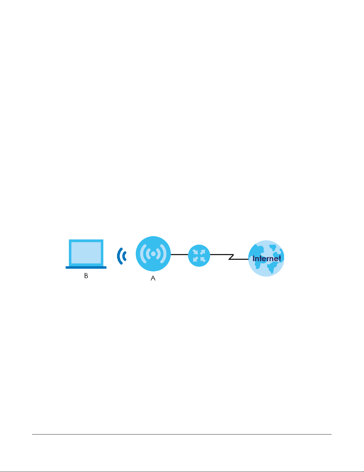
5.2 Connecting to the Internet from an Access Point
This section gives you an example of how to set up an access point (AP) and wireless client (a notebook
(B), in this example) for wireless communication. B can access the Internet through the access point (A)
wirelessly.
Figure 12 Wireless Access Point Connection to the Internet
5.3 Connecting to the WAP6906’s Wireless Network Using WPS
This section gives you an example of how to set up wireless networks using WPS. The following example
uses the WAP6906 as the AP and a WPS-enabled Android smartphone as the wireless client.
The following WPS methods for creating a secure connection are described in the tutorial.
• Push Button Configuration (PBC) - create a secure wireless network simply by pressing a button. See
Section 5.3.1 on page 31.This is the easier method.
• PIN Configuration - create a secure wireless network simply by entering a wireless client's PIN (Personal
Identification Number) in the WAP6906’s interface. See Section 5.3.2 on page 32. This is the more
secure method, since one device can authenticate the other.
WAP6906 User’s Guide
30
Page 31

Chapter 5 Tutorials
5.3.1 Push Button Configuration (PBC)
The WPS button, see Section 1.4 on page 11, can also be used for PBC configurations.
1 Make sure that your WAP6906 is turned on and that it is within range of the wireless client.
2 Go to your phone settings and turn on WiFi. Open the WiFi networks list and tap WPS Push Button or the
WPS icon ( ).
3 Log into WAP6906’s Web Configurator. Make sure WPS is enabled in the Configuration > Networking >
Wireless Network 2.4G or Wireless Network 5G > WPS screen.
4 Navigate to Configuration > Networking > Wireless Network 2.4G or Wireless Network 5G > WPS and
press the Push Button.
Note: Your WAP6906 has a WPS button located on its panel, as well as a WPS button in its
configuration utility. Both buttons have exactly the same function; you can use one or
the other.
Note: It doesn’t matter which button is pressed first. You must press the second button within
two minutes of pressing the first one.
The WAP6906 sends the proper configuration settings to the wireless client. This may take up to two
minutes. Then the wireless client is able to communicate with the WAP6906 securely.
The following figure shows you how to set up wireless network and security by pressing a button on both
WAP6906 and wireless client (the Android smartphone in this example).
WAP6906 User’s Guide
31
Page 32

Chapter 5 Tutorials
Wireless Client
SECURITY INFO
COMMUNICATION
WITHIN 2 MINUTES
AP
Figure 13 Example WPS Process: PBC Method
5.3.2 PIN Configuration
1 Go to your phone settings and turn on WiFi. Open the WiFi networks list and tap WPS PIN Entry to get a
2 Enter the client’s PIN number to the PIN field in the Networking > Wireless Network 2.4G or Wireless
3 Click the WPS PIN button (or button next to the PIN field) on the WAP6906’s WPS screen within two
When you use the PIN configuration method, you need to check the client’s PIN number and use the
configuration interface of the WAP6906.
PIN number.
Network 5G > WPS screen on the WAP6906.
minutes.
The WAP6906 authenticates the wireless client and sends the proper configuration settings to the
wireless client. This may take up to two minutes. Then the wireless client is able to communicate with the
WAP6906 securely.
The following figure shows an example of how to set up wireless network and security on WAP6906 and
wireless client (the Android smartphone in this example) by using PIN method.
WAP6906 User’s Guide
32
Page 33

Chapter 5 Tutorials
Authentication by PIN
SECURITY INFO
WITHIN 2 MINUTES
Wireless Client
COMMUNICATION
Enter WPS PIN
WPS
from other device:
WPS
START
AP
Figure 14 Example WPS Process: PIN Method
5.4 Connecting the WAP6906 to an AP
The WAP6906 allows you to extend the original AP coverage.
• Selecting an AP from an Automatically Detected List - create a secure wireless network simply by
selecting an AP from a list of detected APs. See Section 5.4.1 on page 34. This is the easier method.
• Selecting an AP by Manually Entering Security Information - create a secure wireless network by
manually entering the AP’s wireless security settings in the WAP6906’s interface. See Section 5.4.2 on
page 34. This is useful when the AP is hidden.
WAP6906 User’s Guide
33
Page 34

Chapter 5 Tutorials
5.4.1 Selecting an AP from an Automatically Detected List
Follow the steps below to create a secure wireless network by selecting an AP from a list of detected
APs. The instructions require that your hardware is connected (see the Quick Start Guide) and you are
logged into the Web Configurator through your LAN connection (see Section 2.2 on page 15).
1 Open the Networking > AP Connection > AP List screen. Select an AP form the SSID column. Type the
WiFi key if wireless security is enabled on the selected AP and click Connect.
Check the connection status to see if your WAP6906 is successfully connected to the AP.
5.4.2 Selecting an AP by Manually Entering Security Information
This example shows you how to configure wireless security settings with the following parameters on your
WAP6906.
SSID Zyxel
Security WPA(2)-PSK
WiFi Key 1234567890
Follow the steps below to create a secure wireless network by manually entering the AP’s wireless
security settings in the WAP6906’s interface.
The instructions require that your hardware is connected (see the Quick Start Guide) and you are
logged into the Web Configurator through your LAN connection (see Section 2.2 on page 15).
WAP6906 User’s Guide
34
Page 35

Chapter 5 Tutorials
1 Open the Networking > AP Connection > Station or Basic screen. Type the SSID of the AP into the
Wireless Name (SSID) field, set the security settings and click Apply.
Check the connection status to see if your WAP6906 is successfully connected to the AP.
WAP6906 User’s Guide
35
Page 36

PART II
Technical Reference
36
Page 37

6.1 Overview
This chapter discusses read-only information related to the device state of the WAP6906.
6.2 What You Can Do
• Use the Log screen (Section 6.3 on page 37) to view the logs for the categories such as system
maintenance, system errors, and so on.
• Use the Wireless Monitor screen (Section 6.4 on page 38) to view the wireless stations or AP that are
currently associated with the WAP6906.
• Use the MBSS Monitor screen (Section 6.5 on page 41) to view the Multiple Basic Server Sets (MBSS) on
the WAP6906. A MBSS allows you to use one access point to provide several BSSs simultaneously. You
can then assign varying security types to different SSIDs. Wireless clients can use different SSIDs to
associate with the same access point.
• Use the Multicast Monitor screen (Section 6.6 on page 43) to view the multicast group information.
CHAPTER 6
Monitor
6.3 Log
Click to open the Monitor menu. Use the View Log screen to see the logged messages for the
WAP6906.
Log entries in red indicate system error logs. The log wraps around and deletes the old entries after it fills.
Click Monitor > Log > View Log.
WAP6906 User’s Guide
37
Page 38

Chapter 6 Monitor
Figure 15 Monitor > Log
The following table describes the labels in this screen.
Table 8 Monitor > Log
LABEL DESCRIPTION
# This field is a sequential value and is not associated with a specific entry.
Time This field displays the time the log was recorded.
Message This field states the reason for the log.
Refresh Click Refresh to renew the log screen.
Clear Click Clear to delete all the logs.
6.4 Wireless Monitor
Go to Monitor > Wireless Monitor. View a detailed summary of the AP’s general settings and details of its
Associated Devices. Association means that a wireless client (for example, your network or computer
with a wireless network card) has connected successfully to the AP (or wireless router) using the same
SSID, channel and security settings.
WAP6906 User’s Guide
38
Page 39

Chapter 6 Monitor
Figure 16 Monitor > Wireless Monitor (Downlink)
WAP6906 User’s Guide
39
Page 40

Chapter 6 Monitor
Figure 17 Monitor > Wireless Monitor (Uplink)
The following table describes the labels in this screen.
Table 9 Monitor > Wireless Monitor
LABEL DESCRIPTION
Wi-Fi Interface This shows the name of the wireless network on the WAP6906.
Device Mode This shows the operating mode to which the WAP6906 is set - Access Point (AP), Repeater
(AP), Repeater (STA), or Station (STA).
802.11 Mode This shows the wireless standard the WAP6906 uses.
Bandwidth This shows the wireless bandwidth allowed for wireless clients or the WAP6906 when the
WAP6906 is connected to an AP.
AP MAC Address
(BSSID)
Channel This shows the current channel the WAP6906 uses to associate with the wireless client or AP.
Association Status This shows whether the WAP6906 is connected to an AP.
Associated Devices
Count
Association Table This will display a table that shows a summary of each device connected to the WAP6906.
Packets Received
Successfully
Bytes Received This shows the number of bytes that have been received by the WAP6906.
This shows the MAC Address of your WAP6906 or the AP to which the WAP6906 is
connected.
This shows the number of devices connected to the WAP6906.
This shows the number of packets that have been successfully received by the WAP6906.
WAP6906 User’s Guide
40
Page 41

Chapter 6 Monitor
Table 9 Monitor > Wireless Monitor
LABEL DESCRIPTION
Packets Transmitted
Successfully
Bytes Transmitted This shows the number of bytes that have been transmitted by the WAP6906.
Association Table The table displays after you click the Association Table button.
Access Point This shows the MAC address of the AP to which the WAP6906 is connected.
Wi-Fi Client This shows the MAC address of the wireless client which is associated with the WAP6906.
VAP This shows the SSID name of the wireless network to which the WAP6906 is connecting.
RSSI (dbm) This shows the RSSI (Received Signal Strength Indicator) of the WAP6906’s wireless
TX PHY Data Rate
(Mbps)
SNR This Signal-to-Noise Ratio (SNR) is the ratio between the received signal power and the
Rx Bytes This shows the number of bytes that have been received by the connected AP or client.
Tx Bytes This shows the number of bytes that have been transmitted by the connected AP or client.
BW This shows the wireless bandwidth allowed for the connected wireless clients.
Time Associated This shows the total amount of time (in seconds) the WAP6906 has been associated with the
Refresh Click the Refresh button to refresh the WAP6906 settings.
This shows the number of packets that have been successfully transmitted by the WAP6906.
connection.
This shows the current data rate of the connected AP or client.
received noise power.
AP or client.
6.5 MBSS Monitor
Go to Monitor > MBSS Monitor. A Multiple Basic Server Set (MBSS) allows you to use your WAP6906 to
provide several Basic Server Sets (BSS) simultaneously. This screen shows a summary of the BSS
configured in your WAP6906.
WAP6906 User’s Guide
41
Page 42
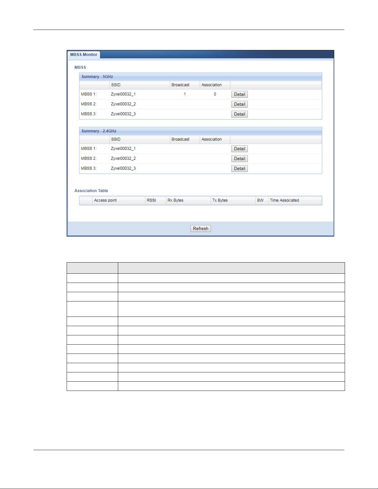
Figure 18 Monitor > MBSS Monitor
Chapter 6 Monitor
The following table describes the labels in this screen.
Table 10 Monitor > MBSS Monitor
LABEL DESCRIPTION
SSID This shows the name for each BSS.
Broadcast This shows the broadcast status of a specific MBSS. It shows 0 for Disable and 1 for Enable.
Association This shows the number of devices connected to each BSS.
Detail Click this button and a summary table describing the BSS is displayed under the MBSS
Summary table.
Association Table The table displays after you click the Detail button.
Access Point This shows the SSID name for each BSS.
RSSI (dbm) This shows the RSSI (Received Signal Strength Indicator) of the wireless connection.
Rx Bytes This shows the number of bytes that have been received by the connected client.
Tx Bytes This shows the number of bytes that have been transmitted by the connected client.
BW This shows the wireless bandwidth allowed for the connected wireless clients.
Time Associated This shows the total amount of time (in seconds) the client has been associated with the BSS.
Refresh Click this button to refresh the status of the MBSS.
WAP6906 User’s Guide
42
Page 43

6.6 Multicast Monitor
Go to Monitor > Multicast Monitor. Traditionally, IP packets are transmitted in one of either two ways Unicast (1 sender to 1 recipient) or Broadcast (1 sender to everybody on the network). Multicast delivers
IP packets to just a group of hosts on the network. This screen shows a summary of the multicast group IP
addresses.
Figure 19 Monitor > Multicast Monitor
The following table describes the labels in this screen.
Chapter 6 Monitor
Table 11 Monitor > Multicast Monitor
LABEL DESCRIPTION
Multicast IP This field displays the multicast group IP address.
Interface This field displays the interface that belongs to the multicast group.
Refresh Click this button to refresh the status of the WDS.
WAP6906 User’s Guide
43
Page 44

7.1 Overview
This chapter describes how to configure LAN settings.
A Local Area Network (LAN) is a shared communication system to which many computers are
attached. A LAN is a computer network limited to the immediate area, usually the same building or floor
of a building. The LAN screens can help you configure the WAP6906’s IPv4 and IPv6 addresses on the
LAN.
Figure 20 LAN Setup
CHAPTER 7
Network
7.2 What You Can Do
Use the Networking screen (Section 7.4 on page 45) to change the LAN IP address for your WAP6906.
7.3 What You Need To Know
The actual physical connection determines whether the WAP6906 ports are LAN or WAN ports. There are
two separate IP networks, one inside the LAN network and the other outside the WAN network as shown
next.
WAP6906 User’s Guide
44
Page 45

Figure 21 LAN and WAN IP Addresses
7.4 Networking Screen
Use this screen to change your basic LAN settings. Click Network > Networking.
Chapter 7 Network
Figure 22 Network > Networking
The following table describes the labels in this screen.
Table 12 Network > Networking
LABEL DESCRIPTION
LAN IP Select DHCP to deploy the WAP6906 as a DHCP client in the network. When you enable this,
the WAP6906 gets its IP address from the network’s DHCP server (for example, your ISP or
router). Users connected to the WAP6906 can now access the network (i.e., the Internet if
the IP address is given by the ISP or a router with Internet access). When you select this, you
cannot enter an IP address for your WAP6906 in the field below.
Select Static IP if you want to specify the IP address of your WAP6906. Or if your ISP or
network administrator gave you a static IP address to access the network or the Internet.
IP Address Type the IPv4 address of your WAP6906 in dotted decimal notation if you select Static IP.
WAP6906 User’s Guide
45
Page 46

Chapter 7 Network
Table 12 Network > Networking (continued)
LABEL DESCRIPTION
IP Subnet Mask The subnet mask specifies the network number portion of an IP address.
Gateway IP Enter a gateway IPv4 address (if your ISP or network administrator gave you one) in this field.
IPv6 Select DHCP to obtain an IPv6 address using IPv6 stateful autoconfiguration.
Select SLAAC(StateLess Address Auto-Configuration) to obtain an IPv6 address using IPv6
stateless autoconfiguration.
Select Static to configure a fixed IPv6 address for the WAP6906.
WAN IPv6 Address Enter an IPv6 IP address that your ISP gave to you for the WAN interface.
Prefix Length Enter the address prefix length to specify how many most significant bits in an IPv6 address
IPv6 Gateway Enter the IP address of the next-hop gateway. The gateway is a router or switch on the same
Apply Click Apply to save your changes back to the WAP6906.
Reset Click Reset to begin configuring this screen afresh.
compose the network address.
segment as your WAP6906's interface(s). The gateway helps forward packets to their
destinations.
WAP6906 User’s Guide
46
Page 47

8.1 Overview
This chapter discusses how to configure the wireless network settings in your WAP6906. See the
appendices for more detailed information about wireless networks.
The following figure provides an example of a wireless network.
Figure 23 Example of a Wireless Network
CHAPTER 8
Wireless LAN
The wireless network is the part in the blue circle. In this wireless network, devices A and B are called
wireless clients. The wireless clients use the access point (AP) to interact with other devices (such as the
printer) or with the Internet. Your WAP6906 is the AP in the above example.
8.2 What You Can Do
Wireless screens vary according to the device mode you are using. See Chapter 3 on page 22 for more
information on device modes.
WAP6906 User’s Guide
47
Page 48

Chapter 8 Wireless LAN
• Use the Basic screen to enable the Wireless LAN, enter the SSID and select the wireless security mode
(Section 8.4 on page 49).
• Use the Advanced screen to configure wireless advanced settings such as the wireless band, channel
bandwidth, and priority. (Section 8.5 on page 51).
• Use the WPS screen to quickly set up a wireless network with strong security, without having to
configure security settings manually (Section 8.6 on page 51).
• Use the MAC Filter screen to allow or deny wireless stations based on their MAC addresses from
connecting to the WAP6906 (Section 8.7 on page 52).
• Use the WDS screen to configure Wireless Distribution System on your WAP6906 (Section 8.8 on page
53).
• Use the MBSS screen to enable and configure multiple BSSs on the WAP6906 (Section 8.8 on page 53).
8.3 What You Should Know
Every wireless network must follow these basic guidelines.
• Every wireless client in the same wireless network must use the same SSID.
The SSID is the name of the wireless network. It stands for Service Set IDentity.
• If two wireless networks overlap, they should use different channels.
Like radio stations or television channels, each wireless network uses a specific channel, or frequency,
to send and receive information.
• Every wireless client in the same wireless network must use security compatible with the AP.
Security stops unauthorized devices from using the wireless network. It can also protect the
information that is sent in the wireless network.
8.3.1 Wireless Security Overview
The following sections introduce different types of wireless security you can set up in the wireless
network.
8.3.2 MAC Address Filter
Every wireless client has a unique identification number, called a MAC address.1 A MAC address is
usually written using twelve hexadecimal characters
To get the MAC address for each wireless client, see the appropriate User’s Guide or other
documentation.
You can use the MAC address filter to tell the AP which wireless clients are allowed or not allowed to use
the wireless network. If a wireless client is allowed to use the wireless network, it still has to have the
correct settings (SSID, channel, and security). If a wireless client is not allowed to use the wireless
network, it does not matter if it has the correct settings.
1. Some wireless devices, such as scanners, can detect wireless networks but cannot use wireless networks. These
kinds of wireless devices might not have MAC addresses.
2. Hexadecimal characters are 0, 1, 2, 3, 4, 5, 6, 7, 8, 9, A, B, C, D, E, and F.
2
; for example, 00A0C5000002 or 00:A0:C5:00:00:02.
WAP6906 User’s Guide
48
Page 49

This type of security does not protect the information that is sent in the wireless network. Furthermore,
there are ways for unauthorized devices to get the MAC address of an authorized wireless client. Then,
they can use that MAC address to use the wireless network.
8.3.3 Encryption
Wireless networks can use encryption to protect the information that is sent in the wireless network.
Encryption is like a secret code. If you do not know the secret code, you cannot understand the
message.
Table 13 Types of Encryption
Weakest No Security
Strongest WPA2-PSK
Usually, you should set up the strongest encryption that every wireless client in the wireless network
supports.
Chapter 8 Wireless LAN
NO AUTHENTICATION
Static WEP
WPA-PSK
Many types of encryption use a key to protect the information in the wireless network. The longer the
key, the stronger the encryption. Every wireless client in the wireless network must have the same key.
8.3.4 WPS
WiFi Protected Setup (WPS) is an industry standard specification, defined by the WiFi Alliance. WPS
allows you to quickly set up a wireless network with strong security, without having to configure security
settings manually. Depending on the devices in your network, you can either press a button (on the
device itself, or in its configuration utility) or enter a PIN (Personal Identification Number) in the devices.
Then, they connect and set up a secure network by themselves.
8.3.5 WDS
Wireless Distribution System or WDS security is used between bridged APs. It is independent of the
security between the AP and any wireless clients. If you do not enable WDS security, traffic between APs
is not encrypted. When WDS security is enabled, both APs must use the same pre-shared key.
8.4 Basic Wireless Network Screen
Use this screen to enable the wireless LAN, enter the SSID and select the wireless security mode.
Note: If you are configuring the WAP6906 from a computer connected to the wireless LAN
and you change the WAP6906’s SSID, channel or security settings, you will lose your
wireless connection when you press Apply to confirm. You must then change the
wireless settings of your computer to match the WAP6906’s new settings.
Click Networking > Wireless Network 5G/2.4G > Basic to open the Basic screen.
WAP6906 User’s Guide
49
Page 50

Chapter 8 Wireless LAN
Figure 24 Networking > Wireless Network 5G/2.4G > Basic
The following table describes the general wireless LAN labels in this screen.
Table 14 Networking > Wireless Network 5G/2.4G > Basic
LABEL DESCRIPTION
Radio Enable Click the check box to activate the wireless LAN.
Network
Name(SSID)
Broadcast SSID Select this to have the WAP6906 broadcast the SSID in the area. If it is disabled the WAP6906 does
Channel
Selection
Current
Channel
Encryption Select the data encryption method the WAP6906 uses.
Pre-Shared Key Enter the password that lets you connect to the WAP6906. Your password should be in a string of
Group Key
Update Timer
Apply Click Apply to save your changes back to the WAP6906.
Cancel Click Cancel to reload the previous configuration for this screen.
The SSID identifies the Service Set with which a wireless station is associated. Wireless stations
associating to the access point (AP) must have the same SSID. Enter a descriptive name (up to 32
printable 7-bit ASCII characters) for the wireless LAN.
not broadcast the SSID.
Select the operating channel for the WAP6906 and its wireless clients. The options vary
depending on the frequency band and the country you are in.
Select Auto and the WAP6906 selects a channel automatically.
Select Smart Channel Selection (SCS), and the WAP6906 decides to switch channels, monitors
several channels and chooses the one with higher capacity.
This displays the channel the WAP6906 is currently using.
Select WPA2-AES or WPA2 + WPA (mixed mode) to add security on this wireless network. The
wireless clients which want to associate to this network must have same wireless security settings
as this device. Or you can select No Security to allow any client to associate this network without
authentication.
ASCII characters between 8 and 63 or hexadecimal characters between 8 and 64.
The Group Key Update Timer is the rate at which the WAP6906 sends a new group key out to
clients.
WAP6906 User’s Guide
50
Page 51

Chapter 8 Wireless LAN
8.5 Advanced Wireless Network Screen
Use this screen to select the advanced wireless settings for the WAP6906.
Click Networking > Wireless Network 2.4G > Advanced. The screen appears as shown.
Figure 25 Networking > Wireless Network 2.4G > Advanced
The following table describes the labels in this screen.
Table 15 Networking > Wireless Network 2.4G > Advanced
LABEL DESCRIPTION
Wireless Band Select the wireless standard you want to use for your wireless network.
Channel
Bandwidth
Beacon Interval This is the time lag between each of the beacons sent by the wireless network.
DTIM Period The Delivery Traffic Indication Map (DTIM) period, is the moment the WAP6906 will broadcast
Short Guard
Interval
Apply Click Apply to save your changes to the WAP6906.
Cancel Click Cancel to reload the previous configuration for this screen.
8.6 WPS Screen
Select the channel bandwidth you want to use for your wireless network.
Select whether the WAP6906 uses a wireless channel width of 20MHz or 40MHz. A standard
20MHz channel offers transfer speeds of up to 150Mbps whereas a 40MHz channel uses two
standard channels and offers speeds of up to 300 Mbps.
any buffered broadcast frames, after the WAP6906 broadcasts the beacon. Enter 1, and the
WAP6906 will transmit broadcast frames after every beacon, enter 2 and the WAP6906 will
transmit every other beacon.
Enable the Short Guard Interval to ensure the WAP6906 transmissions do not interfere with
each other.
Use this screen to enable/disable WPS, view or generate a new PIN number and check current WPS
status. To open this screen, click Networking > Wireless Network 5G/2.4G > WPS.
WAP6906 User’s Guide
51
Page 52

Chapter 8 Wireless LAN
Note: With WPS, wireless clients can only connect to the 5GHz or 2.4GHz wireless network using
the first SSID on the WAP6906. This means you cannot connect to the SSIDs created in
the MBSS screen via WPS.
Figure 26 Networking > Wireless Network 5G/2.4G > WPS
The following table describes the labels in this screen.
Table 16 Networking > Wireless Network 5G/2.4G > WPS
LABEL DESCRIPTION
WPS Setup
State Select Configured to enable WPS and do NOT change the wireless security key after the WPS
connection is established.
WPS PBC Click the Push Button to perform wireless security information synchronization using the Push
WPS PIN Use this field to type the same PIN number generated in the wireless station’s utility to perform
Device PIN Enable Select this to allow the WAP6906 to create a new PIN number. Wireless clients then can use
PIN Number This displays a PIN number last time system generated. Click Generate to generate a new PIN
Apply Click Apply to save your changes back to the WAP6906.
Cancel Click Cancel to get this screen information afresh.
8.7 MAC Filter
The MAC filter screen allows you to configure the WAP6906 to give exclusive access to devices (Allow)
or exclude devices from accessing the WAP6906 (Reject). Every Ethernet device has a unique MAC
(Media Access Control) address. The MAC address is assigned at the factory and consists of six pairs of
Select Unconfigured to enable WPS but change the wireless security key after the WPS
connection is established.
Select Disabled to turn off WPS.
Button Configuration (PBC) Method.
wireless security information synchronization using the PIN Configuration Method.
Click the WPS PIN button to establish the synchronization. The PIN should be between 4 and 8
characters.
the generated PIN number to perform wireless security information synchronization with the
WAP6906 via WPS.
number.
WAP6906 User’s Guide
52
Page 53

Chapter 8 Wireless LAN
hexadecimal characters, for example, 00:A0:C5:00:00:02. You need to know the MAC address of the
devices to configure this screen.
To change your WAP6906’s MAC filter settings, click Networking > Wireless Network 5G/2.4G > MAC
Filter. The screen appears as shown.
Figure 27 Networking > Wireless Network 5G/2.4G > MAC Filter
The following table describes the labels in this menu.
Table 17 Networking > Wireless Network 5G/2.4G > MAC Filter
LABEL DESCRIPTION
Interface Select the SSID for which you want to configure MAC filtering.
Policy Define the filter action for the list of specified MAC addresses.
Select None to deactivate the MAC filtering rule you configure below.
Select Allow to permit access to the WAP6906. MAC addresses not listed will be denied access to
the WAP6906.
Select Reject to block access to the WAP6906. MAC addresses not listed will be allowed to
access the WAP6906.
MAC Address Enter the MAC addresses of the wireless station that are allowed or denied access to the
WAP6906 in these address fields. Enter the MAC addresses in a valid MAC address format, that is,
six hexadecimal character pairs, for example, 12:34:56:78:9a:bc.
Apply Click Apply if you want to add the MAC Address to the list.
Remove Click Remove if you want to discard the MAC Address from the list.
MAC filter list This field shows the MAC addresses of the wireless station that are allowed or denied access to
the selected SSID.
Cancel Click Cancel to reload the previous configuration for this screen.
8.8 MBSS Screen
A Multiple Basic Server Set (MBSS) allows you to use your WAP6906 to provide several Basic Server Sets
(BSS) simultaneously. You can then assign varying security types to different SSIDs. Wireless clients can
use different SSIDs to associate with the same access point.
To open this screen, click Networking > Wireless Network 5G/2.4G > MBSS.
WAP6906 User’s Guide
53
Page 54

Chapter 8 Wireless LAN
Figure 28 Networking > Wireless Network 5G/2.4G > MBSS
The following table describes the labels in this screen.
Table 18 Networking > Wireless Network 5G/2.4G > MBSS
LABEL DESCRIPTION
Network Name
(SSID)
Broadcast SSID Click on the check box if you want your SSID to be broadcasted to users in the area.
Encryption Select the type of security to protect the information through the wireless network.
Pre-Shared Key Type the password users need to connect to this BSS.
Apply Click Apply to save your changes back to the WAP6906.
Cancel Click Cancel to reload the previous configuration for this screen.
Type a name for one of your BSS. Click on the check box next to each Network Name to
enable the BSS.
You can enable up to 4 simultaneous BSSs on your WAP6906.
WAP6906 User’s Guide
54
Page 55

9.1 Overview
This chapter discusses how to establish a wireless connection between your WAP6906 and another AP or
wireless network. It allows you to connect to and/or extend the existing wireless network.
Use these screens to choose an access point that you want the WAP6906 to connect to. You should
know the security settings of the target AP.
Chapter 9 AP Connection
CHAPTER 9
AP Connection
9.2 What You Can Do
• Use the Station screen to enable WiFi, enter the SSID and configure the wireless security between the
WAP6906 and an existing wireless network (Section 8.4 on page 49).
• Use the AP List screen to scan the wireless networks in the WAP6906’s area (Section 8.7 on page 52).
You can also select an AP from the list and enter its WiFi password to connect the wireless network.
• Use the WPS screen to quickly set up a wireless network with strong security between your WAP6906
and the AP, without having to configure security settings manually (Section 8.6 on page 51).
9.3 Station Screen
Use this screen to manually enter the SSID and security settings of the AP to which you want the
WAP6906 to connect. This screen allows you to set a profile so that the WAP6906 will automatically try to
connect to the AP specified in the profile each time the WAP6906 is turned on.
Click Networking > AP Connection > Station to open this screen.
Figure 29 Networking > AP Connection > Station
WAP6906 User’s Guide
55
Page 56

The following table describes the general wireless LAN labels in this screen.
Table 19 Networking > AP Connection > Station
LABEL DESCRIPTION
Network
Name(SSID)
Connection
Status
Encryption Select the data encryption method the wireless network uses.
Pre-Shared Key Enter the password that the WAP6906 uses to connect to the wireless network.
Apply Click Apply to save your changes back to the WAP6906.
Cancel Click Cancel to reload the previous configuration for this screen.
Enter the name of the wireless network to which the WAP6906 is connecting
This shows whether the WAP6906 is already connected, attempting to connect, or not
connected to a wireless network.
9.4 AP List Screen
You can use this screen to select an AP and enter its WiFi password to connect the wireless network.
After connecting to an AP its SSID is automatically displayed in the Station screen.
Click Networking > AP Connection > AP List. The screen appears as shown.
Figure 30 Networking > AP Connection > AP List
WAP6906 User’s Guide
56
Page 57

Chapter 9 AP Connection
The following table describes the labels in this screen.
Table 20 Networking > AP Connection > AP List
LABEL DESCRIPTION
Connection Status This shows whether the WAP6906 is already connected, attempting to connect, or not
Current SSID This shows the name of the AP to which your WAP6906 is currently connected.
SSID This shows the network name of the AP the WAP6906 can detect.
MAC Address This shows the MAC address of the AP.
Channel This shows the channel the AP uses.
RSSI (dbm) This shows the strength of the AP’s radio signal measured in dbm.
Security This shows Yes if the WAP6906 needs a security password to connect to the AP. It shows No if
AP This shows the name of the AP you click and try to connect.
Passphrase The Passphrase input box displays when the Security column is Yes for the selected SSID. Enter
Connect The Connect button appears at the end of the table after you click on a SSID.
Rescan Click Rescan to refresh the list of APs available.
connected to a wireless network.
the WAP6906 does not need a password to connect.
the password for this wireless network in the Passphrase input box.
Click this button to connect to the selected AP.
9.5 WPS Screen
Use this screen to enable/disable WPS, view or generate a new PIN number. To open this screen, click
Networking > AP Connection > WPS.
Figure 31 Networking > AP Connection > WPS
The following table describes the labels in this screen.
Table 21 Networking > AP Connection > WPS
LABEL DESCRIPTION
WPS Setup
WPS PBC Click the Push Button to perform wireless security information synchronization using the Push
WPS PIN This field displays the PIN number for the WAP6906 you will use to perform wireless security
Button Configuration (PBC) Method.
information synchronization using the PIN Configuration Method.
Click the WPS PIN button to establish the synchronization. Click Generate to create a new PIN
and display it in the WPS PIN field.
WAP6906 User’s Guide
57
Page 58

Chapter 9 AP Connection
Table 21 Networking > AP Connection > WPS (continued)
LABEL DESCRIPTION
Apply Click Apply to save your changes back to the WAP6906.
Cancel Click Cancel to get this screen information afresh.
WAP6906 User’s Guide
58
Page 59

10.1 Overview
This chapter provides information on the Maintenance screen.
10.2 What You Can Do
• Use the Password screen to set the password (Section 10.3 on page 59).
• Use the Time screen to change your WAP6906’s time and date (Section 10.4 on page 60).
• Use the Firmware Upgrade screen to update firmware (Section 10.5 on page 61).
• Use the Telnet screen to enable or disable access to the WAP6906 using Telnet (Section 10.6 on page
62).
• Use the Restore screen to back up and restore device configurations (Section 10.7 on page 63).
• Use the Restart screen to reboot the WAP6906 without turning the power off (Section 10.8 on page
65).
CHAPTER 10
Maintenance
10.3 Password Screen
Use this screen to set the web configurator password. Click Maintenance > Password. The following
screen displays.
Figure 32 Maintenance > Password
WAP6906 User’s Guide
59
Page 60

The following table describes the labels in this screen.
Table 22 Maintenance > Password
LABEL DESCRIPTION
Old Password Type the default password or the existing password you use to access the system in this field.
New Password Type your new system password (up to 30 characters). Note that as you type a password,
Retype to Confirm Type the new password again in this field.
Apply Click Apply to save your changes back to the WAP6906.
Cancel Click Cancel to reload the previous configuration for this screen.
10.4 Time Screen
Use this screen to configure the WAP6906’s time based on your local time zone. To change your
WAP6906’s time and date, click Maintenance > Time. The screen appears as shown.
Figure 33 Maintenance > Time
Chapter 10 Maintenance
the screen displays an asterisk (*) for each character you type.
The following table describes the labels in this screen.
Table 23 Maintenance > Time
LABEL DESCRIPTION
Manual Select this radio button to enter the time and date manually. If you configure a new time
and date, Time Zone and Daylight Saving at the same time, the new time and date you
entered has priority and the Time Zone and Daylight Saving settings do not affect it.
New Time
(hh:mm:ss)
This field displays the last updated time from the time server or the last time configured
manually.
When you select Manual, enter the new time in this field and then click Apply.
WAP6906 User’s Guide
60
Page 61
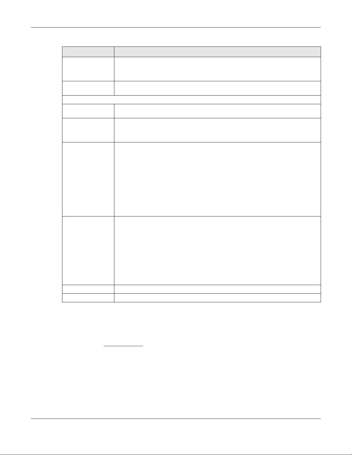
Chapter 10 Maintenance
Table 23 Maintenance > Time (continued)
LABEL DESCRIPTION
New Date
(yyyy/mm/dd)
Get from Time Server Select this radio button to have the WAP6906 get the time and date from the time server(s)
Time Zone Setup
Time Zone Choose the time zone of your location. This will set the time difference between your time
Daylight Saving
Enable
Start Date Configure the day and time when Daylight Saving Time starts if you selected Daylight
End Date Configure the day and time when Daylight Saving Time ends if you selected Daylight
This field displays the last updated date from the time server or the last date configured
manually.
When you select Manual, enter the new date in this field and then click Apply.
you specified below.
zone and Greenwich Mean Time (GMT).
Daylight saving is a period from late spring to early fall when many countries set their clocks
ahead of normal local time by one hour to give more daytime light in the evening.
Select this option if you use Daylight Saving Time.
Saving Enable. The at field uses the 24 hour format. Here are a couple of examples:
Daylight Saving Time starts in most parts of the United States on the second Sunday of
March. Each time zone in the United States starts using Daylight Saving Time at 2 A.M. local
time. So in the United States you would select Second, Sunday, March and select 2 in the at
field.
Daylight Saving Time starts in the European Union on the last Sunday of March. All of the
time zones in the European Union start using Daylight Saving Time at the same moment (1
A.M. GMT or UTC). So in the European Union you would select Last, Sunday, March. The time
you select in the at field depends on your time zone. In Germany for instance, you would
select 2 because Germany's time zone is one hour ahead of GMT or UTC (GMT+1).
Saving Enable. The at field uses the 24 hour format. Here are a couple of examples:
Daylight Saving Time ends in the United States on the first Sunday of November. Each time
zone in the United States stops using Daylight Saving Time at 2 A.M. local time. So in the
United States you would select First, Sunday, November and select 2 in the at field.
Daylight Saving Time ends in the European Union on the last Sunday of October. All of the
time zones in the European Union stop using Daylight Saving Time at the same moment (1
A.M. GMT or UTC). So in the European Union you would select Last, Sunday, October. The
time you select in the at field depends on your time zone. In Germany for instance, you
would select 2 because Germany's time zone is one hour ahead of GMT or UTC (GMT+1).
Apply Click Apply to save your changes back to the WAP6906.
Cancel Click Cancel to begin configuring this screen afresh.
10.5 Firmware Upgrade Screen
Find firmware at www.zyxel.com in a file that (usually) uses the system model name with a “*.bin”
extension, e.g., “WAP6906.bin”. The upload process uses HTTP (Hypertext Transfer Protocol) and may
take up to two minutes. After a successful upload, the system will reboot.
Click Maintenance > Firmware Upgrade. Follow the instructions in this screen to upload firmware to your
WAP6906.
WAP6906 User’s Guide
61
Page 62

Chapter 10 Maintenance
Figure 34 Maintenance > Firmware Upgrade
The following table describes the labels in this screen.
Table 24 Maintenance > Firmware Upgrade
LABEL DESCRIPTION
Firmware Upgrade
File Path Click Choose file to find the.bin file you want to upload. Remember that you must decompress
compressed (.zip) files before you can upload them.
Upload Click Upload to begin the upload process. This process may take up to two minutes.
Note: Do not turn off the WAP6906 while firmware upload is in progress!
Wait until the upgrade process is complete.
The WAP6906 automatically restarts causing a temporary network disconnect. In some operating
systems, you may see the following icon on your desktop.
Figure 35 Network Temporarily Disconnected
After the WAP6906 restarts, log in again and check your new firmware version in the Status screen.
10.6 Telnet Screen
The WAP6906 can be managed either locally or remotely via a Telnet connection. You can use Telnet to
access the WAP6906’s command line interface. Click Maintenance > Telnet.
Select Enable to allow users to access the WAP6906’s CLI using Telnet and click Apply.
WAP6906 User’s Guide
62
Page 63

Figure 36 Maintenance > Telnet
10.7 Restore Screen
Click Maintenance > Restore. Information related to factory defaults, backup configuration, and
restoring configuration appears as shown next.
Figure 37 Maintenance > Restore
Chapter 10 Maintenance
10.7.1 Backup Configuration
Backup configuration allows you to back up (save) the WAP6906’s current configuration to a file on your
computer. Once your WAP6906 is configured and functioning properly, it is highly recommended that
you back up your configuration file before making configuration changes. The backup configuration file
will be useful in case you need to return to your previous settings.
Click Backup to save the WAP6906’s current configuration to your computer.
WAP6906 User’s Guide
63
Page 64

10.7.2 Restore Configuration
Restore configuration allows you to upload a new or previously saved configuration file from your
computer to your WAP6906.
Table 25 Maintenance > Restore Configuration
LABEL DESCRIPTION
File Path Click Choose file to find the file you want to upload. Remember that you must decompress
compressed (.ZIP) files before you can upload them.
Upload Click Upload to begin the upload process.
Note: Do not turn off the WAP6906 while configuration file upload is in progress.
After you see a “configuration upload successful” screen, you must then wait one minute before
logging into the WAP6906 again.
The WAP6906 automatically restarts in this time causing a temporary network disconnect. In some
operating systems, you may see the following icon on your desktop.
Figure 38 Temporarily Disconnected
Chapter 10 Maintenance
If you uploaded the default configuration file you may need to change the IP address of your computer
to be in the same subnet as that of the default WAP6906 IP address (192.168.1.2). Refer to your operating
system’s help files for details on how to set up your computer’s IP address.
10.7.3 Back to Factory Defaults
Click the Reset button to clear all user-entered configuration information and return the WAP6906 to its
factory defaults. The following warning screen appears.
Figure 39 Reset Warning Message
You can also press the RESET button on the rear panel for more than 5 seconds to reset the factory
defaults of your WAP6906. Refer to Section 1.7 on page 14 for more information on the resetting the
WAP6906.
10.7.4 Restore but retain IP settings
Press the Reset button in this section to restore all configuration settings, but it retains IP settings.
WAP6906 User’s Guide
64
Page 65

10.8 Restart Screen
System restart allows you to reboot the WAP6906 without turning the power off. Click Maintenance >
Restart. The following screen displays. Click Reboot to have the WAP6906 restart. This does not affect the
WAP6906's configuration.
Figure 40 Maintenance > Restart
Chapter 10 Maintenance
WAP6906 User’s Guide
65
Page 66

CHAPTER 11
Troubleshooting
This chapter offers some suggestions to solve problems you might encounter. The potential problems are
divided into the following categories.
• Power, Hardware Connections, and LEDs
• WAP6906 Access and Login
• Internet Access
• Resetting the WAP6906 to Its Factory Defaults
• Wireless Problems
11.1 Power, Hardware Connections, and LEDs
The WAP6906 does not turn on. None of the LEDs turn on.
1 Make sure the WAP6906 is plugged in to an appropriate power source. Make sure the power source is
turned on.
2 Disconnect and re-connect the WAP6906.
3 Remove the WAP6906 from the outlet. Then connect an electrical device that you know works into the
same power outlet. This checks the status of the power outlet.
4 If the problem continues, contact the vendor.
One of the LEDs does not behave as expected.
1 Make sure you understand the normal behavior of the LED. See Section 1.4 on page 11.
2 Check the hardware connections. See the Quick Start Guide.
3 Inspect your cables for damage. Contact the vendor to replace any damaged cables.
4 Disconnect and re-connect the WAP6906.
5 If the problem continues, contact the vendor.
WAP6906 User’s Guide
66
Page 67

Chapter 11 Troubleshooting
11.2 WAP6906 Access and Login
I forgot the password.
1 The default password is on the device label.
2 If this does not work, you have to reset the device to its factory defaults. See Section 11.4 on page 69.
I cannot see or access the Login screen in the Web Configurator.
1 Make sure you are using the correct address.
• The default web address (URL) of the WAP6906 is http://zyxelsetup (for Windows) or http://
zyxelsetup.local (for Mac).
• The WAP6906’s IP address is http://192.168.1.5.
2 Check the hardware connections, and make sure the LEDs are behaving as expected. See the Quick
Start Guide and Section 1.4 on page 11.
3 Make sure your Internet browser does not block pop-up windows and has JavaScript and Java
enabled.
4 Reset the device to its factory defaults, and try to access the WAP6906 with the default address.
5 If the problem continues, contact the network administrator or vendor, or try one of the advanced
suggestions.
Advanced Suggestions
• If your computer is connected wirelessly, use a computer that is connected to a LAN port.
I can see the Login screen, but I cannot log in to the WAP6906.
1 Make sure you have entered the password correctly. The default password is in the device label.
2 This can happen when you fail to log out properly from your last session. Try logging in again after 5
minutes.
3 Disconnect and re-connect the WAP6906.
4 If this does not work, you have to reset the device to its factory defaults. See Section 11.4 on page 69.
WAP6906 User’s Guide
67
Page 68

11.3 Internet Access
I cannot access the Internet.
1 Check the hardware connections, and make sure the LEDs are behaving as expected. See the Quick
Start Guide.
2 Try to connect directly to the gateway. If you can access the Internet, check that the WAP6906 has
connected to the gateway by checking the Status screen. See Section 3.4 on page 24.
3 If you are trying to access the Internet wirelessly, make sure the wireless settings in the wireless client are
the same as the settings in the WAP6906.
4 Disconnect all the cables from your device, and follow the directions in the Quick Start Guide again.
5 If the problem continues, contact the network administrator or vendor.
Chapter 11 Troubleshooting
I cannot access the Internet anymore. I had access to the Internet (with the WAP6906), but my
Internet connection is not available anymore.
1 Check the hardware connections, and make sure the LEDs are behaving as expected. See the Quick
Start Guide and Section 1.4 on page 11.
2 Reboot the WAP6906.
3 Try to connect directly to the gateway. If you can access the Internet, check that the WAP6906 has
connected to the gateway by checking the Status screen. See Section 3.4 on page 24.
4 If the problem continues, contact the network administrator or vendor.
The Internet connection is slow or intermittent.
1 There might be a lot of traffic on the network. Look at the LEDs, and check Section 1.4 on page 11. If the
WAP6906 is sending or receiving a lot of information, try closing some programs that use the Internet,
especially peer-to-peer applications.
2 Check the signal strength. If the signal strength is low, try moving the WAP6906 closer to the AP if
possible, and look around to see if there are any devices that might be interfering with the wireless
network (for example, microwaves, other wireless networks, and so on).
3 Reboot the WAP6906.
4 If the problem continues, contact the network administrator or vendor, or try one of the advanced
suggestions.
WAP6906 User’s Guide
68
Page 69

Chapter 11 Troubleshooting
11.4 Resetting the WAP6906 to Its Factory Defaults
If you reset the WAP6906, you lose all of the changes you have made. The WAP6906 re-loads its default
settings, and the password resets to the back-label default key. You have to make all of your changes
again.
You will lose all of your changes when you reset the WAP6906 to its factory defaults.
To reset the WAP6906,
1 Make sure the power LED is on.
2 Press the RESET button for longer than 5 seconds, the Power LED begins to blink, to set the WAP6906 back
to its factory-default configuration.
OR
3 Click Maintenance > Restore and then click Reset.
If the WAP6906 restarts automatically, wait for the WAP6906 to finish restarting, and log in to the Web
Configurator. The password is in the device label.
If the WAP6906 does not restart automatically, disconnect and reconnect the WAP6906. Then, follow the
directions above again.
11.5 Wireless Problems
I cannot access the WAP6906 or ping any computer from the WLAN.
1 Make sure the WAP6906 is working and the wireless LAN is enabled on the WAP6906.
2 Make sure the wireless adapter on the wireless client is working properly.
3 Make sure the wireless adapter installed on your computer is IEEE 802.11 compatible and supports the
same wireless standard as the WAP6906.
4 Make sure your computer (with a wireless adapter installed) is within the transmission range of the
WAP6906.
5 Check that both the WAP6906 and your wireless station are using the same wireless and wireless security
settings.
6 Make sure traffic between the WLAN and the LAN is not blocked by the MAC Address List of the
WAP6906. See Section 8.7 on page 52.
WAP6906 User’s Guide
69
Page 70

Wireless LAN Topologies
This section discusses ad-hoc and infrastructure wireless LAN topologies.
Ad-hoc Wireless LAN Configuration
The simplest WLAN configuration is an independent (Ad-hoc) WLAN that connects a set of computers
with wireless adapters (A, B, C). Any time two or more wireless adapters are within range of each other,
they can set up an independent network, which is commonly referred to as an ad-hoc network or
Independent Basic Service Set (IBSS). The following diagram shows an example of notebook computers
using wireless adapters to form an ad-hoc wireless LAN.
Figure 41 Peer-to-Peer Communication in an Ad-hoc Network
APPENDIX A
Wireless LANs
BSS
A Basic Service Set (BSS) exists when all communications between wireless clients or between a wireless
client and a wired network client go through one access point (AP).
Intra-BSS traffic is traffic between wireless clients in the BSS. When Intra-BSS is enabled, wireless client A
and B can access the wired network and communicate with each other. When Intra-BSS is disabled,
wireless client A and B can still access the wired network but cannot communicate with each other.
WAP6906 User’s Guide
70
Page 71

Figure 42 Basic Service Set
Appendix A Wireless LANs
ESS
An Extended Service Set (ESS) consists of a series of overlapping BSSs, each containing an access point,
with each access point connected together by a wired network. This wired connection between APs is
called a Distribution System (DS).
This type of wireless LAN topology is called an Infrastructure WLAN. The Access Points not only provide
communication with the wired network but also mediate wireless network traffic in the immediate
neighborhood.
An ESSID (ESS IDentification) uniquely identifies each ESS. All access points and their associated wireless
clients within the same ESS must have the same ESSID in order to communicate.
WAP6906 User’s Guide
71
Page 72

Figure 43 Infrastructure WLAN
Appendix A Wireless LANs
Channel
RTS/CTS
A channel is the radio frequency(ies) used by wireless devices to transmit and receive data. Channels
available depend on your geographical area. You may have a choice of channels (for your region) so
you should use a channel different from an adjacent AP (access point) to reduce interference.
Interference occurs when radio signals from different access points overlap causing interference and
degrading performance.
Adjacent channels partially overlap however. To avoid interference due to overlap, your AP should be
on a channel at least five channels away from a channel that an adjacent AP is using. For example, if
your region has 11 channels and an adjacent AP is using channel 1, then you need to select a channel
between 6 or 11.
A hidden node occurs when two stations are within range of the same access point, but are not within
range of each other. The following figure illustrates a hidden node. Both stations (STA) are within range
of the access point (AP) or wireless gateway, but out-of-range of each other, so they cannot "hear"
each other, that is they do not know if the channel is currently being used. Therefore, they are
considered hidden from each other.
WAP6906 User’s Guide
72
Page 73

Appendix A Wireless LANs
Figure 44 RTS/CTS
Note: Stations cannot hear each other. They can hear the AP.
When station A sends data to the AP, it might not know that the station B is already using the channel. If
these two stations send data at the same time, collisions may occur when both sets of data arrive at the
AP at the same time, resulting in a loss of messages for both stations.
RTS/CTS is designed to prevent collisions due to hidden nodes. An RTS/CTS defines the biggest size data
frame you can send before an RTS (Request To Send)/CTS (Clear to Send) handshake is invoked.
When a data frame exceeds the RTS/CTS value you set (between 0 to 2432 bytes), the station that wants
to transmit this frame must first send an RTS (Request To Send) message to the AP for permission to send
it. The AP then responds with a CTS (Clear to Send) message to all other stations within its range to notify
them to defer their transmission. It also reserves and confirms with the requesting station the time frame
for the requested transmission.
Stations can send frames smaller than the specified RTS/CTS directly to the AP without the RTS (Request
To Send)/CTS (Clear to Send) handshake.
You should only configure RTS/CTS if the possibility of hidden nodes exists on your network and the "cost"
of resending large frames is more than the extra network overhead involved in the RTS (Request To
Send)/CTS (Clear to Send) handshake.
If the RTS/CTS value is greater than the Fragmentation Threshold value (see next), then the RTS (Request
To Send)/CTS (Clear to Send) handshake will never occur as data frames will be fragmented before
they reach RTS/CTS size.
Note: Enabling the RTS Threshold causes redundant network overhead that could negatively
affect the throughput performance instead of providing a remedy.
Fragmentation Threshold
A Fragmentation Threshold is the maximum data fragment size (between 256 and 2432 bytes) that can
be sent in the wireless network before the AP will fragment the packet into smaller data frames.
A large Fragmentation Threshold is recommended for networks not prone to interference while you
should set a smaller threshold for busy networks or networks that are prone to interference.
WAP6906 User’s Guide
73
Page 74

If the Fragmentation Threshold value is smaller than the RTS/CTS value (see previously) you set then the
RTS (Request To Send)/CTS (Clear to Send) handshake will never occur as data frames will be
fragmented before they reach RTS/CTS size.
Preamble Type
Preamble is used to signal that data is coming to the receiver. Short and long refer to the length of the
synchronization field in a packet.
Short preamble increases performance as less time sending preamble means more time for sending
data. All IEEE 802.11 compliant wireless adapters support long preamble, but not all support short
preamble.
Use long preamble if you are unsure what preamble mode other wireless devices on the network
support, and to provide more reliable communications in busy wireless networks.
Use short preamble if you are sure all wireless devices on the network support it, and to provide more
efficient communications.
Use the dynamic setting to automatically use short preamble when all wireless devices on the network
support it, otherwise the WAP6906 uses long preamble.
Appendix A Wireless LANs
Note: The wireless devices MUST use the same preamble mode in order to communicate.
IEEE 802.11g Wireless LAN
IEEE 802.11g is fully compatible with the IEEE 802.11b standard. This means an IEEE 802.11b adapter can
interface directly with an IEEE 802.11g access point (and vice versa) at 11 Mbps or lower depending on
range. IEEE 802.11g has several intermediate rate steps between the maximum and minimum data
rates. The IEEE 802.11g data rate and modulation are as follows:
Table 26 IEEE 802.11g
DATA RATE (MBPS) MODULATION
1 DBPSK (Differential Binary Phase Shift Keyed)
2 DQPSK (Differential Quadrature Phase Shift Keying)
5.5 / 11 CCK (Complementary Code Keying)
6/9/12/18/24/36/48/54 OFDM (Orthogonal Frequency Division Multiplexing)
Wireless Security Overview
Wireless security is vital to your network to protect wireless communication between wireless clients,
access points and the wired network.
Wireless security methods available on the WAP6906 are data encryption, wireless client authentication,
restricting access by device MAC address and hiding the WAP6906 identity.
WAP6906 User’s Guide
74
Page 75

Appendix A Wireless LANs
The following figure shows the relative effectiveness of these wireless security methods available on your
WAP6906.
Table 27 Wireless Security Levels
SECURITY
LEVEL
Least Secure
Most Secure
SECURITY TYPE
Unique SSID (Default)
Unique SSID with Hide SSID Enabled
MAC Address Filtering
WEP Encryption
IEEE802.1x EAP with RADIUS Server Authentication
WiFi Protected Access (WPA)
WPA2
Note: You must enable the same wireless security settings on the WAP6906 and on all wireless
clients that you want to associate with it.
IEEE 802.1x
In June 2001, the IEEE 802.1x standard was designed to extend the features of IEEE 802.11 to support
extended authentication as well as providing additional accounting and control features. It is
supported by Windows XP and a number of network devices. Some advantages of IEEE 802.1x are:
• User based identification that allows for roaming.
• Support for RADIUS (Remote Authentication Dial In User Service, RFC 2138, 2139) for centralized user
• Support for EAP (Extensible Authentication Protocol, RFC 2486) that allows additional authentication
RADIUS
RADIUS is based on a client-server model that supports authentication, authorization and accounting.
The access point is the client and the server is the RADIUS server. The RADIUS server handles the following
tasks:
• Authentication
•Authorization
• Accounting
profile and accounting management on a network RADIUS server.
methods to be deployed with no changes to the access point or the wireless clients.
Determines the identity of the users.
Determines the network services available to authenticated users once they are connected to the
network.
Keeps track of the client’s network activity.
RADIUS is a simple package exchange in which your AP acts as a message relay between the wireless
client and the network RADIUS server.
WAP6906 User’s Guide
75
Page 76

Types of RADIUS Messages
The following types of RADIUS messages are exchanged between the access point and the RADIUS
server for user authentication:
• Access-Request
Sent by an access point requesting authentication.
• Access-Reject
Sent by a RADIUS server rejecting access.
• Access-Accept
Sent by a RADIUS server allowing access.
• Access-Challenge
Sent by a RADIUS server requesting more information in order to allow access. The access point sends
a proper response from the user and then sends another Access-Request message.
The following types of RADIUS messages are exchanged between the access point and the RADIUS
server for user accounting:
• Accounting-Request
Sent by the access point requesting accounting.
• Accounting-Response
Sent by the RADIUS server to indicate that it has started or stopped accounting.
Appendix A Wireless LANs
In order to ensure network security, the access point and the RADIUS server use a shared secret key,
which is a password, they both know. The key is not sent over the network. In addition to the shared key,
password information exchanged is also encrypted to protect the network from unauthorized access.
Types of EAP Authentication
This section discusses some popular authentication types: EAP-MD5, EAP-TLS, EAP-TTLS, PEAP and LEAP.
Your wireless LAN device may not support all authentication types.
EAP (Extensible Authentication Protocol) is an authentication protocol that runs on top of the IEEE 802.1x
transport mechanism in order to support multiple types of user authentication. By using EAP to interact
with an EAP-compatible RADIUS server, an access point helps a wireless station and a RADIUS server
perform authentication.
The type of authentication you use depends on the RADIUS server and an intermediary AP(s) that
supports IEEE 802.1x.
For EAP-TLS authentication type, you must first have a wired connection to the network and obtain the
certificate(s) from a certificate authority (CA). A certificate (also called digital IDs) can be used to
authenticate users and a CA issues certificates and guarantees the identity of each certificate owner.
EAP-MD5 (Message-Digest Algorithm 5)
MD5 authentication is the simplest one-way authentication method. The authentication server sends a
challenge to the wireless client. The wireless client ‘proves’ that it knows the password by encrypting the
password with the challenge and sends back the information. Password is not sent in plain text.
WAP6906 User’s Guide
76
Page 77

Appendix A Wireless LANs
However, MD5 authentication has some weaknesses. Since the authentication server needs to get the
plaintext passwords, the passwords must be stored. Thus someone other than the authentication server
may access the password file. In addition, it is possible to impersonate an authentication server as MD5
authentication method does not perform mutual authentication. Finally, MD5 authentication method
does not support data encryption with dynamic session key. You must configure WEP encryption keys for
data encryption.
EAP-TLS (Transport Layer Security)
With EAP-TLS, digital certifications are needed by both the server and the wireless clients for mutual
authentication. The server presents a certificate to the client. After validating the identity of the server,
the client sends a different certificate to the server. The exchange of certificates is done in the open
before a secured tunnel is created. This makes user identity vulnerable to passive attacks. A digital
certificate is an electronic ID card that authenticates the sender’s identity. However, to implement EAPTLS, you need a Certificate Authority (CA) to handle certificates, which imposes a management
overhead.
EAP-TTLS (Tunneled Transport Layer Service)
EAP-TTLS is an extension of the EAP-TLS authentication that uses certificates for only the server-side
authentications to establish a secure connection. Client authentication is then done by sending
username and password through the secure connection, thus client identity is protected. For client
authentication, EAP-TTLS supports EAP methods and legacy authentication methods such as PAP, CHAP,
MS-CHAP and MS-CHAP v2.
PEAP (Protected EAP)
Like EAP-TTLS, server-side certificate authentication is used to establish a secure connection, then use
simple username and password methods through the secured connection to authenticate the clients,
thus hiding client identity. However, PEAP only supports EAP methods, such as EAP-MD5, EAP-MSCHAPv2
and EAP-GTC (EAP-Generic Token Card), for client authentication. EAP-GTC is implemented only by
Cisco.
LEAP
LEAP (Lightweight Extensible Authentication Protocol) is a Cisco implementation of IEEE 802.1x.
Dynamic WEP Key Exchange
The AP maps a unique key that is generated with the RADIUS server. This key expires when the wireless
connection times out, disconnects or re-authentication times out. A new WEP key is generated each
time re-authentication is performed.
If this feature is enabled, it is not necessary to configure a default encryption key in the wireless security
configuration screen. You may still configure and store keys, but they will not be used while dynamic
WEP is enabled.
Note: EAP-MD5 cannot be used with Dynamic WEP Key Exchange
For added security, certificate-based authentications (EAP-TLS, EAP-TTLS and PEAP) use dynamic keys for
data encryption. They are often deployed in corporate environments, but for public deployment, a
WAP6906 User’s Guide
77
Page 78

simple user name and password pair is more practical. The following table is a comparison of the
features of authentication types.
Table 28 Comparison of EAP Authentication Types
Mutual Authentication No Yes Yes Yes Yes
Certificate – Client No Yes Optional Optional No
Certificate – Server No Yes Yes Yes No
Dynamic Key Exchange No Yes Yes Yes Yes
Credential Integrity None Strong Strong Strong Moderate
Deployment Difficulty Easy Hard Moderate Moderate Moderate
Client Identity Protection No No Yes Yes No
WPA and WPA2
WiFi Protected Access (WPA) is a subset of the IEEE 802.11i standard. WPA2 (IEEE 802.11i) is a wireless
security standard that defines stronger encryption, authentication and key management than WPA.
Key differences between WPA or WPA2 and WEP are improved data encryption and user
authentication.
Appendix A Wireless LANs
EAP-MD5 EAP-TLS EAP-TTLS PEAP LEAP
If both an AP and the wireless clients support WPA2 and you have an external RADIUS server, use WPA2
for stronger data encryption. If you don't have an external RADIUS server, you should use WPA2-PSK
(WPA2-Pre-Shared Key) that only requires a single (identical) password entered into each access point,
wireless gateway and wireless client. As long as the passwords match, a wireless client will be granted
access to a WLAN.
If the AP or the wireless clients do not support WPA2, just use WPA or WPA-PSK depending on whether
you have an external RADIUS server or not.
Select WEP only when the AP and/or wireless clients do not support WPA or WPA2. WEP is less secure
than WPA or WPA2.
Encryption
WPA improves data encryption by using Temporal Key Integrity Protocol (TKIP), Message Integrity Check
(MIC) and IEEE 802.1x. WPA2 also uses TKIP when required for compatibility reasons, but offers stronger
encryption than TKIP with Advanced Encryption Standard (AES) in the Counter mode with Cipher block
chaining Message authentication code Protocol (CCMP).
TKIP uses 128-bit keys that are dynamically generated and distributed by the authentication server. AES
(Advanced Encryption Standard) is a block cipher that uses a 256-bit mathematical algorithm called
Rijndael. They both include a per-packet key mixing function, a Message Integrity Check (MIC) named
Michael, an extended initialization vector (IV) with sequencing rules, and a re-keying mechanism.
WPA and WPA2 regularly change and rotate the encryption keys so that the same encryption key is
never used twice.
The RADIUS server distributes a Pairwise Master Key (PMK) key to the AP that then sets up a key hierarchy
and management system, using the PMK to dynamically generate unique data encryption keys to
WAP6906 User’s Guide
78
Page 79

encrypt every data packet that is wirelessly communicated between the AP and the wireless clients. This
all happens in the background automatically.
The Message Integrity Check (MIC) is designed to prevent an attacker from capturing data packets,
altering them and resending them. The MIC provides a strong mathematical function in which the
receiver and the transmitter each compute and then compare the MIC. If they do not match, it is
assumed that the data has been tampered with and the packet is dropped.
By generating unique data encryption keys for every data packet and by creating an integrity
checking mechanism (MIC), with TKIP and AES it is more difficult to decrypt data on a WiFi network than
WEP and difficult for an intruder to break into the network.
The encryption mechanisms used for WPA(2) and WPA(2)-PSK are the same. The only difference
between the two is that WPA(2)-PSK uses a simple common password, instead of user-specific
credentials. The common-password approach makes WPA(2)-PSK susceptible to brute-force passwordguessing attacks but it’s still an improvement over WEP as it employs a consistent, single, alphanumeric
password to derive a PMK which is used to generate unique temporal encryption keys. This prevent all
wireless devices sharing the same encryption keys. (a weakness of WEP)
User Authentication
WPA and WPA2 apply IEEE 802.1x and Extensible Authentication Protocol (EAP) to authenticate wireless
clients using an external RADIUS database. WPA2 reduces the number of key exchange messages from
six to four (CCMP 4-way handshake) and shortens the time required to connect to a network. Other
WPA2 authentication features that are different from WPA include key caching and pre-authentication.
These two features are optional and may not be supported in all wireless devices.
Appendix A Wireless LANs
Key caching allows a wireless client to store the PMK it derived through a successful authentication with
an AP. The wireless client uses the PMK when it tries to connect to the same AP and does not need to go
with the authentication process again.
Pre-authentication enables fast roaming by allowing the wireless client (already connecting to an AP) to
perform IEEE 802.1x authentication with another AP before connecting to it.
Wireless Client WPA Supplicants
A wireless client supplicant is the software that runs on an operating system instructing the wireless client
how to use WPA. At the time of writing, the most widely available supplicant is the WPA patch for
Windows XP, Funk Software's Odyssey client.
The Windows XP patch is a free download that adds WPA capability to Windows XP's built-in "Zero
Configuration" wireless client. However, you must run Windows XP to use it.
WPA(2) with RADIUS Application Example
To set up WPA(2), you need the IP address of the RADIUS server, its port number (default is 1812), and the
RADIUS shared secret. A WPA(2) application example with an external RADIUS server looks as follows. "A"
is the RADIUS server. "DS" is the distribution system.
1 The AP passes the wireless client's authentication request to the RADIUS server.
2 The RADIUS server then checks the user's identification against its database and grants or denies
network access accordingly.
WAP6906 User’s Guide
79
Page 80

Appendix A Wireless LANs
3 A 256-bit Pairwise Master Key (PMK) is derived from the authentication process by the RADIUS server and
the client.
4 The RADIUS server distributes the PMK to the AP. The AP then sets up a key hierarchy and management
system, using the PMK to dynamically generate unique data encryption keys. The keys are used to
encrypt every data packet that is wirelessly communicated between the AP and the wireless clients.
Figure 45 WPA(2) with RADIUS Application Example
WPA(2)-PSK Application Example
A WPA(2)-PSK application looks as follows.
1 First enter identical passwords into the AP and all wireless clients. The Pre-Shared Key (PSK) must consist
of between 8 and 63 ASCII characters or 64 hexadecimal characters (including spaces and symbols).
2 The AP checks each wireless client's password and allows it to join the network only if the password
matches.
3 The AP and wireless clients generate a common PMK (Pairwise Master Key). The key itself is not sent over
the network, but is derived from the PSK and the SSID.
4 The AP and wireless clients use the TKIP or AES encryption process, the PMK and information exchanged
in a handshake to create temporal encryption keys. They use these keys to encrypt data exchanged
between them.
WAP6906 User’s Guide
80
Page 81

Figure 46 WPA(2)-PSK Authentication
Security Parameters Summary
Refer to this table to see what other security parameters you should configure for each authentication
method or key management protocol type. MAC address filters are not dependent on how you
configure these security features.
Appendix A Wireless LANs
Table 29 Wireless Security Relational Matrix
AUTHENTICATION METHOD/
KEY MANAGEMENT
PROTOCOL
Open None No Disable
Open WEP No Enable with Dynamic WEP Key
Shared WEP No Enable with Dynamic WEP Key
WPA TKIP/AES No Enable
WPA-PSK TKIP/AES Yes Disable
WPA2 TKIP/AES No Enable
WPA2-PSK TKIP/AES Yes Disable
Antenna Overview
An antenna couples RF signals onto air. A transmitter within a wireless device sends an RF signal to the
antenna, which propagates the signal through the air. The antenna also operates in reverse by
capturing RF signals from the air.
ENCRYPTION
METHOD
ENTER MANUAL
KEY
Yes Enable without Dynamic WEP Key
Yes Disable
Yes Enable without Dynamic WEP Key
Yes Disable
IEEE 802.1X
Enable without Dynamic WEP Key
Positioning the antennas properly increases the range and coverage area of a wireless LAN.
WAP6906 User’s Guide
81
Page 82

Antenna Characteristics
Frequency
An antenna in the frequency of 2.4GHz or 5GHz is needed to communicate efficiently in a wireless LAN
Radiation Pattern
A radiation pattern is a diagram that allows you to visualize the shape of the antenna’s coverage area.
Antenna Gain
Antenna gain, measured in dB (decibel), is the increase in coverage within the RF beam width. Higher
antenna gain improves the range of the signal for better communications.
For an indoor site, each 1 dB increase in antenna gain results in a range increase of approximately 2.5%.
For an unobstructed outdoor site, each 1dB increase in gain results in a range increase of approximately
5%. Actual results may vary depending on the network environment.
Antenna gain is sometimes specified in dBi, which is how much the antenna increases the signal power
compared to using an isotropic antenna. An isotropic antenna is a theoretical perfect antenna that
sends out radio signals equally well in all directions. dBi represents the true gain that the antenna
provides.
Appendix A Wireless LANs
Types of Antennas for WLAN
There are two types of antennas used for wireless LAN applications.
• Omni-directional antennas send the RF signal out in all directions on a horizontal plane. The coverage
area is torus-shaped (like a donut) which makes these antennas ideal for a room environment. With a
wide coverage area, it is possible to make circular overlapping coverage areas with multiple access
points.
• Directional antennas concentrate the RF signal in a beam, like a flashlight does with the light from its
bulb. The angle of the beam determines the width of the coverage pattern. Angles typically range
from 20 degrees (very directional) to 120 degrees (less directional). Directional antennas are ideal for
hallways and outdoor point-to-point applications.
Positioning Antennas
In general, antennas should be mounted as high as practically possible and free of obstructions. In
point-to–point application, position both antennas at the same height and in a direct line of sight to
each other to attain the best performance.
For omni-directional antennas mounted on a table, desk, and so on, point the antenna up. For omnidirectional antennas mounted on a wall or ceiling, point the antenna down. For a single AP application,
place omni-directional antennas as close to the center of the coverage area as possible.
For directional antennas, point the antenna in the direction of the desired coverage area.
WAP6906 User’s Guide
82
Page 83

APPENDIX B
Customer Support
In the event of problems that cannot be solved by using this manual, you should contact your vendor. If
you cannot contact your vendor, then contact a Zyxel office for the region in which you bought the
device.
See http://www.zyxel.com/homepage.shtml and also
http://www.zyxel.com/about_zyxel/zyxel_worldwide.shtml for the latest information.
Please have the following information ready when you contact an office.
Required Information
• Product model and serial number.
• Warranty Information.
• Date that you received your device.
• Brief description of the problem and the steps you took to solve it.
Corporate Headquarters (Worldwide)
Taiwan
• Zyxel Communications Corporation
• http://www.zyxel.com
Asia
China
• Zyxel Communications (Shanghai) Corp.
Zyxel Communications (Beijing) Corp.
Zyxel Communications (Tianjin) Corp.
• http://www.zyxel.cn
India
•Zyxel Technology India Pvt Ltd
• http://www.zyxel.in
Kazakhstan
•Zyxel Kazakhstan
• http://www.zyxel.kz
WAP6906 User’s Guide
83
Page 84

Korea
• Zyxel Korea Corp.
• http://www.zyxel.kr
Malaysia
• Zyxel Malaysia Sdn Bhd.
• http://www.zyxel.com.my
Pakistan
• Zyxel Pakistan (Pvt.) Ltd.
• http://www.zyxel.com.pk
Philippines
• Zyxel Philippines
• http://www.zyxel.com.ph
Singapore
• Zyxel Singapore Pte Ltd.
• http://www.zyxel.com.sg
Appendix B Customer Support
Europe
Taiwan
• Zyxel Communications Corporation
• http://www.zyxel.com/tw/zh/
Thailand
• Zyxel Thailand Co., Ltd
• http://www.zyxel.co.th
Vietnam
• Zyxel Communications Corporation-Vietnam Office
• http://www.zyxel.com/vn/vi
Austria
•Zyxel Deutschland GmbH
• http://www.zyxel.de
Belarus
•Zyxel BY
• http://www.zyxel.by
WAP6906 User’s Guide
84
Page 85

Appendix B Customer Support
Belgium
• Zyxel Communications B.V.
• http://www.zyxel.com/be/nl/
• http://www.zyxel.com/be/fr/
Bulgaria
•Zyxel България
• http://www.zyxel.com/bg/bg/
Czech Republic
• Zyxel Communications Czech s.r.o
• http://www.zyxel.cz
Denmark
• Zyxel Communications A/S
• http://www.zyxel.dk
Estonia
• Zyxel Estonia
• http://www.zyxel.com/ee/et/
Finland
• Zyxel Communications
• http://www.zyxel.fi
France
•Zyxel France
• http://www.zyxel.fr
Germany
•Zyxel Deutschland GmbH
• http://www.zyxel.de
Hungary
• Zyxel Hungary & SEE
• http://www.zyxel.hu
Italy
• Zyxel Communications Italy
• http://www.zyxel.it/
WAP6906 User’s Guide
85
Page 86

Appendix B Customer Support
Latvia
•Zyxel Latvia
• http://www.zyxel.com/lv/lv/homepage.shtml
Lithuania
•Zyxel Lithuania
• http://www.zyxel.com/lt/lt/homepage.shtml
Netherlands
• Zyxel Benelux
• http://www.zyxel.nl
Norway
• Zyxel Communications
• http://www.zyxel.no
Poland
• Zyxel Communications Poland
• http://www.zyxel.pl
Romania
• Zyxel Romania
• http://www.zyxel.com/ro/ro
Russia
• Zyxel Russia
• http://www.zyxel.ru
Slovakia
• Zyxel Communications Czech s.r.o. organizacna zlozka
• http://www.zyxel.sk
Spain
• Zyxel Communications ES Ltd
• http://www.zyxel.es
Sweden
• Zyxel Communications
• http://www.zyxel.se
Switzerland
•Studerus AG
WAP6906 User’s Guide
86
Page 87

• http://www.zyxel.ch/
Turkey
• Zyxel Turkey A.S.
• http://www.zyxel.com.tr
UK
• Zyxel Communications UK Ltd.
• http://www.zyxel.co.uk
Ukraine
•Zyxel Ukraine
• http://www.ua.zyxel.com
Latin America
Argentina
• Zyxel Communication Corporation
• http://www.zyxel.com/ec/es/
Appendix B Customer Support
Brazil
• Zyxel Communications Brasil Ltda.
• https://www.zyxel.com/br/pt/
Ecuador
• Zyxel Communication Corporation
• http://www.zyxel.com/ec/es/
Middle East
Israel
• Zyxel Communication Corporation
• http://il.zyxel.com/homepage.shtml
Middle East
• Zyxel Communication Corporation
• http://www.zyxel.com/me/en/
WAP6906 User’s Guide
87
Page 88

North America
USA
• Zyxel Communications, Inc. - North America Headquarters
• http://www.zyxel.com/us/en/
Oceania
Australia
• Zyxel Communications Corporation
• http://www.zyxel.com/au/en/
Africa
South Africa
• Nology (Pty) Ltd.
• http://www.zyxel.co.za
Appendix B Customer Support
WAP6906 User’s Guide
88
Page 89

Copyright
Copyright © 2018 by Zyxel Communications Corporation.
The contents of this publication may not be reproduced in any part or as a whole, transcribed, stored in a retrieval system, translated into any
language, or transmitted in any form or by any means, electronic, mechanical, magnetic, optical, chemical, photocopying, manual, or
otherwise, without the prior written permission of Zyxel Communications Corporation.
Published by Zyxel Communications Corporation. All rights reserved.
Disclaimer
Zyxel does not assume any liability arising out of the application or use of any products, or software described herein. Neither does it convey any
license under its patent rights nor the patent rights of others. Zyxel further reserves the right to make changes in any products described herein
without notice. This publication is subject to change without notice.
Regulatory Notice and Statement
UNITED STATES of AMERICA
APPENDIX C
Legal Information
CANADA
The following information applies if you use the product within USA area.
FCC EMC Statement
• The device complies with Part 15 of FCC rules. Operation is subject to the following two conditions:
(1) This device may not cause harmful interference, and
(2) This device must accept any interference received, including interference that may cause undesired operation.
• Changes or modifications not expressly approved by the party responsible for compliance could void the user’s authority to operate the
device.
• This product has been tested and complies with the specifications for a Class B digital device, pursuant to Part 15 of the FCC Rules. These
limits are designed to provide reasonable protection against harmful interference in a residential installation. This device generates, uses, and
can radiate radio frequency energy and, if not installed and used according to the instructions, may cause harmful interference to radio
communications. However, there is no guarantee that interference will not occur in a particular installation.
• If this device does cause harmful interference to radio or television reception, which is found by turning the device off and on, the user is
encouraged to try to correct the interference by one or more of the following measures:
• Reorient or relocate the receiving antenna
• Increase the separation between the devices
• Connect the equipment to an outlet other than the receiver’s
• Consult a dealer or an experienced radio/TV technician for assistance
The following information applies if you use the product with RF function within USA area.
FCC Radiation Exposure Statement
• This device complies with FCC RF radiation exposure limits set forth for an uncontrolled environment.
• This transmitter must be at least 27 cm from the user and must not be co-located or operating in conjunction with any other antenna or
transmitter.
• Operation of this device is restricted to indoor use only, except for relevant user's manual mention that this device can be installed into the
external environment.
The following information applies if you use the product within Canada area.
Industry Canada ICES Statement
CAN ICES-3 (B)/NMB-3(B)
WAP6906 User’s Guide
89
Page 90

Appendix C Legal Information
Industry Canada RSS-GEN & RSS-247 Statement
• This device complies with Industry Canada license-exempt RSS standard(s). Operation is subject to the following two conditions: (1) this
device may not cause interference, and (2) this device must accept any interference, including interference that may cause undesired
operation of the device.
• This radio transmitter (2468C-WAP6906) has been approved by Industry Canada to operate with the antenna types listed below with the
maximum permissible gain and required antenna impedance for each antenna type indicated. Antenna types not included in this list,
having a gain greater than the maximum gain indicated for that type, are strictly prohibited for use with this device.
Antenna Information
TYPE MANUFACTURER G AIN CONNECTOR
5G D-B ANT_0 PCB Aristotle 4.74 (5210 MHz), 3.49 (5290 MHz) i-pex
5G D-B ANT_1 PCB Aristotle 4.28 (5210 MHz), 4.02 (5290 MHz) i-pex
5G D-B ANT_2 PCB Aristotle 3.59 (5210 MHz), 3.95 (5290 MHz) i-pex
5G D-B ANT_3 PCB Aristotle 2.47 (5210 MHz), 2.28 (5290 MHz) i-pex
5G M-B ANT_0 PCB Aristotle 4.38 (5530 MHz), 5.09 (5610 MHz)
4.63 (5690 MHz), 3.46 (5775 MHz)
5G M-B ANT_1 PCB Aristotle 3.16 (5530 MHz), 2.82 (5610 MHz)
3.15 (5690 MHz), 2.5 (5775 MHz)
5G M-B ANT_2 PCB Aristotle 3.65 (5530 MHz), 3.99 (5610 MHz)
3.44 (5690 MHz), 3.77 (5775 MHz)
5G M-B ANT_3 PCB Aristotle 1.28 (5530 MHz), 5.79 (5610 MHz)
5.6 (5690 MHz), 6.58 (5775 MHz)
2.4G ANT_0 PCB Aristotle 1.85 (2437 HMz) i-pex
2.4G ANT_1 PCB Aristotle 3.45 (2437 HMz) i-pex
i-pex
i-pex
i-pex
i-pex
If the product with 5G wireless function operating in 5150-5250 MHz and 5725-5850 MHz, the following attention must be paid,
• The device for operation in the band 5150-5250 MHz is only for indoor use to reduce the potential for harmful interference to co-channel
mobile satellite systems.
• For devices with detachable antenna(s), the maximum antenna gain permitted for devices in the band 5725-5850 MHz shall be such that the
equipment still complies with the e.i.r.p. limits specified for point-to-point and non-point-to-point operation as appropriate; and
• The worst-case tilt angle(s) necessary to remain compliant with the e.i.r.p. elevation mask requirement set forth in Section 6.2.2(3) of RSS 247
shall be clearly indicated.
If the product with 5G wireless function operating in 5250-5350 MHz and 5470-5725 MHz, the following attention must be paid.
• For devices with detachable antenna(s), the maximum antenna gain permitted for devices in the bands 5250-5350 MHz and 5470-5725 MHz
shall be such that the equipment still complies with the e.i.r.p. limit.
• Le présent appareil est conforme aux CNR d’Industrie Canada applicables aux appareils radio exempts de licence. L’exploitation est
autorisée aux deux conditions suivantes : (1) l’appareil ne doit pas produire de brouillage, et (2) l’utilisateur de l’appareil doit accepter tout
brouillage radioélectrique subi, même si le brouillage est susceptible d’en compromettre le fonctionnement.
• Le présent émetteur radio (2468C-WAP6906) de modèle s'il fait partie du matériel de catégorieI) a été approuvé par Industrie Canada pour
fonctionner avec les types d'antenne énumérés ci-dessous et ayant un gain admissible maximal et l'impédance requise pour chaque type
d'antenne. Les types d'antenne non inclus dans cette liste, ou dont le gain est supérieur au gain maximal indiqué, sont strictement interdits
pour l'exploitation de l'émetteur.
WAP6906 User’s Guide
90
Page 91

Appendix C Legal Information
Antenna Information
TYPE MANUFACTURER G AIN CONNECTOR
5G D-B ANT_0 PCB Aristotle 4.74 (5210 MHz), 3.49 (5290 MHz) i-pex
5G D-B ANT_1 PCB Aristotle 4.28 (5210 MHz), 4.02 (5290 MHz) i-pex
5G D-B ANT_2 PCB Aristotle 3.59 (5210 MHz), 3.95 (5290 MHz) i-pex
5G D-B ANT_3 PCB Aristotle 2.47 (5210 MHz), 2.28 (5290 MHz) i-pex
5G M-B ANT_0 PCB Aristotle 4.38 (5530 MHz), 5.09 (5610 MHz)
4.63 (5690 MHz), 3.46 (5775 MHz)
5G M-B ANT_1 PCB Aristotle 3.16 (5530 MHz), 2.82 (5610 MHz)
3.15 (5690 MHz), 2.5 (5775 MHz)
5G M-B ANT_2 PCB Aristotle 3.65 (5530 MHz), 3.99 (5610 MHz)
3.44 (5690 MHz), 3.77 (5775 MHz)
5G M-B ANT_3 PCB Aristotle 1.28 (5530 MHz), 5.79 (5610 MHz)
5.6 (5690 MHz), 6.58 (5775 MHz)
2.4G ANT_0 PCB Aristotle 1.85 (2437 HMz) i-pex
2.4G ANT_1 PCB Aristotle 3.45 (2437 HMz) i-pex
Lorsque la fonction sans fil 5G fonctionnant en 5150-5250 MHz and 5725-5850 MHz est activée pour ce produit, il est nécessaire de porter une
attention particulière aux choses suivantes
• Les dispositifs fonctionnant dans la bande 5150-5250 MHz sont réservés uniquement pour une utilisation à l’intérieur afin de réduire les risques
de brouillage préjudiciable aux systèmes de satellites mobiles utilisant les mêmes canaux;
• Pour les dispositifs munis d’antennes amovibles, le gain maximal d'antenne permis (pour les dispositifs utilisant la bande de 5 725 à 5 850 MHz)
doit être conforme à la limite de la p.i.r.e. spécifiée pour l'exploitation point à point et l’exploitation non point à point, selon le cas;
• Les pires angles d’inclinaison nécessaires pour rester conforme à l’exigence de la p.i.r.e. applicable au masque d’élévation, et énoncée à la
section 6.2.2 3) du CNR-247, doivent être clairement indiqués.
Lorsque la fonction sans fil 5G fonctionnant en 5250-5350 MHz et 5470-5725 MHz est activée pour ce produit, il est nécessaire de porter une
attention particulière aux choses suivantes.
• Pour les dispositifs munis d’antennes amovibles, le gain maximal d'antenne permis pour les dispositifs utilisant les bandes de 5 250 à 5 350 MHz
et de 5 470 à 5 725 MHz doit être conforme à la limite de la p.i.r.e.
i-pex
i-pex
i-pex
i-pex
Industry Canada radiation exposure statement
This device complies with IC radiation exposure limits set forth for an uncontrolled environment. This device should be installed and operated
with a minimum distance of 24 cm between the radiator and your body.
Déclaration d’exposition aux radiations:
Cet équipement est conforme aux limites d’exposition aux rayonnements IC établies pour un environnement non contrôlé. Cet équipement doit
être installé et utilisé avec un minimum de 24 cm de distance entre la source de rayonnement et votre corps.
EUROPEAN UNION
The following information applies if you use the product within the European Union.
Declaration of Conformity with Regard to EU Directive 2014/53/EU (Radio Equipment Directive, RED)
• Compliance information for 2.4GHz and/or 5GHz wireless products relevant to the EU and other Countries following the EU Directive 2014/53/
EU (RED). And this product may be used in all EU countries (and other countries following the EU Directive 2014/53/EU) without any limitation
except for the countries mentioned below table:
• In the majority of the EU and other European countries, the 5GHz bands have been made available for the use of wireless local area
networks (LANs). Later in this document you will find an overview of countries in which additional restrictions or requirements or both are
applicable. The requirements for any country may evolve. Zyxel recommends that you check with the local authorities for the latest status of
their national regulations for the 5GHz wireless LANs.
• If this device for operation in the band 5150-5350 MHz, it is for indoor use only.
• This equipment should be installed and operated with a minimum distance of xx cm between the radio equipment and your body.
• The maximum RF power operating for each band as follows:
• The band 2,400 to 2,483.5 MHz is xxx mW,
• The bands 5,150 MHz to 5,350 MHz is xxx mW,
• The 5,470 MHz to 5,725 MHz is xxx mW.
WAP6906 User’s Guide
91
Page 92

Appendix C Legal Information
Български
(Bulgarian)
Español
(Spanish)
Čeština
(Czech)
Dansk (Danish) Undertegnede Zyxel erklærer herved, at følgende udstyr udstyr overholder de væsentlige krav og øvrige relevante krav i
Deutsch
(German)
Eesti keel
(Estonian)
Ελληνικά
(Greek)
English Hereby, Zyxel declares that this device is in compliance with the essential requirements and other relevant provisions of
Français
(French)
Hrvatski
(Croatian)
Íslenska
(Icelandic)
Italiano (Italian) Con la presente Zyxel dichiara che questo attrezzatura è conforme ai requisiti essenziali ed alle altre disposizioni pertinenti
Latviešu valoda
(Latvian)
Lietuvių kalba
(Lithuanian)
Magyar
(Hungarian)
Malti (Maltese) Hawnhekk, Zyxel, jiddikjara li dan tagħmir jikkonforma mal-ħtiġijiet essenzjali u ma provvedimenti o
Nederlands
(Dutch)
Polski (Polish) Niniejszym Zyxel oświadcza, że sprzęt jest zgodny z zasadniczymi wymogami oraz pozostałymi stosownymi postanowieniami
Português
(Portuguese)
С настоящото Zyxel декларира, че това оборудване е в съответствие със съществените изисквания и другите
приложими разпоредбите на Директива 2014/53/ЕC.
National Restrictions
• The Belgian Institute for Postal Services and Telecommunications (BIPT) must be notified of any outdoor wireless link
having a range exceeding 300 meters. Please check http://www.bipt.be for more details.
• Draadloze verbindingen voor buitengebruik en met een reikwijdte van meer dan 300 meter dienen aangemeld te
worden bij het Belgisch Instituut voor postdiensten en telecommunicatie (BIPT). Zie http://www.bipt.be voor meer
gegevens.
• Les liaisons sans fil pour une utilisation en extérieur d’une distance supérieure à 300 mètres doivent être notifiées à
l’Institut Belge des services Postaux et des Télécommunications (IBPT). Visitez http://www.ibpt.be pour de plus amples
détails.
Por medio de la presente Zyxel declara que el equipo cumple con los requisitos esenciales y cualesquiera otras
disposiciones aplicables o exigibles de la Directiva 2014/53/UE..
Zyxel tímto prohlašuje, že tento zařízení je ve shodě se základními požadavky a dalšími příslušnými ustanoveními směrnice
2014/53/EU.
direktiv 2014/53/EU.
National Restrictions
• In Denmark, the band 5150 - 5350 MHz is also allowed for outdoor usage.
• I Danmark må frekvensbåndet 5150 - 5350 også anvendes udendørs.
Hiermit erklärt Zyxel, dass sich das Gerät Ausstattung in Übereinstimmung mit den grundlegenden Anforderungen und den
übrigen einschlägigen Bestimmungen der Richtlinie 2014/53/EU befindet.
Käesolevaga kinnitab Zyxel seadme seadmed vastavust direktiivi 2014/53/EU põhinõuetele ja nimetatud direktiivist
tulenevatele teistele asjakohastele sätetele.
ΜΕ ΤΗΝ ΠΑΡΟΥΣΑ Zyxel ∆ΗΛΩΝΕΙ ΟΤΙ
∆ΙΑΤΑΞΕΙΣ ΤΗΣ Ο∆ΗΓΙΑΣ 2014/53/EE.
Directive 2014/53/EU.
Par la présente Zyxel déclare que l'appareil équipements est conforme aux exigences essentielles et aux autres dispositions
pertinentes de la directive 2014/53/UE.
Zyxel ovime izjavljuje da je radijska oprema tipa u skladu s Direktivom 2014/53/UE.
Hér með lýsir, Zyxel því yfir að þessi búnaður er í samræmi við grunnkröfur og önnur viðeigandi ákvæði tilskipunar 2014/53/
UE.
stabilite dalla direttiva 2014/53/UE.
National Restrictions
• This product meets the National Radio Interface and the requirements specified in the National Frequency Allocation
Table for Italy. Unless this wireless LAN product is operating within the boundaries of the owner's property, its use requires
a “general authorization.” Please check http://www.sviluppoeconomico.gov.it/ for more details.
• Questo prodotto è conforme alla specifiche di Interfaccia Radio Nazionali e rispetta il Piano Nazionale di ripartizione
delle frequenze in Italia. Se non viene installato all 'interno del proprio fondo, l'utilizzo di prodotti Wireless LAN richiede
una “Autorizzazione Generale”. Consultare http://www.sviluppoeconomico.gov.it/ per maggiori dettagli.
Ar šo Zyxel deklarē, ka iekārtas atbilst Direktīvas 2014/53/ES būtiskajām prasībām un citiem ar to saistītajiem noteikumiem.
National Restrictions
• The outdoor usage of the 2.4 GHz band requires an authorization from the Electronic Communications Office. Please
check http://www.esd.lv for more details.
• 2.4 GHz frekvenèu joslas izmantoðanai ârpus telpâm nepiecieðama atïauja no Elektronisko sakaru direkcijas. Vairâk
informâcijas: http://www.esd.lv.
Šiuo Zyxel deklaruoja, kad šis įranga atitinka esminius reikalavimus ir kitas 2014/53/ESDirektyvos nuostatas.
Alulírott, Zyxel nyilatkozom, hogy a berendezés megfelel a vonatkozó alapvetõ követelményeknek és az 2014/53/EU
irányelv egyéb elõírásainak.
fid-Dirrettiva 2014/53/UE.
Hierbij verklaart Zyxel dat het toestel uitrusting in overeenstemming is met de essentiële eisen en de andere relevante
bepalingen van richtlijn 2014/53/UE.
Dyrektywy 2014/53/UE.
Zyxel declara que este equipamento está conforme com os requisitos essenciais e outras disposições da Directiva 2014/53/
UE.
εξοπλισμός ΣΥΜΜΟΡΦΩΝΕΤΑΙ ΠΡΟΣ ΤΙΣ ΟΥΣΙΩ∆ΕΙΣ ΑΠΑΙΤΗΣΕΙΣ ΚΑΙ ΤΙΣ ΛΟΙΠΕΣ ΣΧΕΤΙΚΕΣ
ħrajn relevanti li hemm
WAP6906 User’s Guide
92
Page 93

Appendix C Legal Information
Română
(Romanian)
Slovenčina
(Slovak)
Slovenščina
(Slovene)
Suomi (Finnish) Zyxel vakuuttaa täten että laitteet tyyppinen laite on direktiivin 2014/53/EU oleellisten vaatimusten ja sitä koskevien
Svenska
(Swedish)
Norsk
(Norwegian)
Notes:
1. Although Norway, Switzerland and Liechtenstein are not EU member states, the EU Directive 2014/53/EU has also been implemented in those
countries.
2. The regulatory limits for maximum output power are specified in EIRP. The EIRP level (in dBm) of a device can be calculated by adding the
gain of the antenna used (specified in dBi) to the output power available at the connector (specified in dBm).
Prin prezenta, Zyxel declară că acest echipament este în conformitate cu cerinţele esenţiale şi alte prevederi relevante ale
Directivei 2014/53/UE.
Zyxel týmto vyhlasuje, že zariadenia spĺňa základné požiadavky a všetky príslušné ustanovenia Smernice 2014/53/EÚ.
Zyxel izjavlja, da je ta oprema v skladu z bistvenimi zahtevami in ostalimi relevantnimi določili direktive 2014/53/EU.
direktiivin muiden ehtojen mukainen.
Härmed intygar Zyxel att denna utrustning står I överensstämmelse med de väsentliga egenskapskrav och övriga relevanta
bestämmelser som framgår av direktiv 2014/53/EU.
Erklærer herved Zyxel at dette utstyret er I samsvar med de grunnleggende kravene og andre relevante bestemmelser I
direktiv 2014/53/EU.
List of national codes
COUNTRY ISO 3166 2 LETTER CODE COUNTRY ISO 3166 2 LETTER CODE
Austria AT Liechtenstein LI
Belgium BE Lithuania LT
Bulgaria BG Luxembourg LU
Croatia HR Malta MT
Cyprus CY Netherlands NL
Czech Republic CZ Norway NO
Denmark DK Poland PL
Estonia EE Portugal PT
Finland FI Romania RO
France FR Serbia RS
Germany DE Slovakia SK
Greece GR Slovenia SI
Hungary HU Spain ES
Iceland IS Switzerland CH
Ireland IE Sweden SE
Italy IT Turkey TR
Latvia LV United Kingdom GB
Safety Warnings
• Do not use this product near water, for example, in a wet basement or near a swimming pool.
• Do not expose your device to dampness, dust or corrosive liquids.
• Do not store things on the device.
• Do not obstruct the device ventilation slots as insufficient airflow may harm your device. For example, do not place the device in an
enclosed space such as a box or on a very soft surface such as a bed or sofa.
• Do not install, use, or service this device during a thunderstorm. There is a remote risk of electric shock from lightning.
• Connect ONLY suitable accessories to the device.
• Do not open the device or unit. Opening or removing covers can expose you to dangerous high voltage points or other risks.
• ONLY qualified service personnel should service or disassemble this device. Please contact your vendor for further information.
• Make sure to connect the cables to the correct ports.
• Place connecting cables carefully so that no one will step on them or stumble over them.
• Always disconnect all cables from this device before servicing or disassembling.
• Do not remove the plug and connect it to a power outlet by itself; always attach the plug to the power adaptor first before connecting it to
a power outlet.
• Do not allow anything to rest on the power adaptor or cord and do NOT place the product where anyone can walk on the power adaptor
or cord.
• Please use the provided or designated connection cables/power cables/ adaptors. Connect it to the right supply voltage (for example,
110V AC in North America or 230V AC in Europe). If the power adaptor or cord is damaged, it might cause electrocution. Remove it from the
device and the power source, repairing the power adapter or cord is prohibited. Contact your local vendor to order a new one.
• Do not use the device outside, and make sure all the connections are indoors. There is a remote risk of electric shock from lightning.
WAP6906 User’s Guide
93
Page 94

• CAUTION: Risk of explosion if battery is replaced by an incorrect type, dispose of used batteries according to the instruction. Dispose them at
the applicable collection point for the recycling of electrical and electronic devices. For detailed information about recycling of this
product, please contact your local city office, your household waste disposal service or the store where you purchased the product.
• The following warning statements apply, where the disconnect device is not incorporated in the device or where the plug on the power
supply cord is intended to serve as the disconnect device,
- For permanently connected devices, a readily accessible disconnect device shall be incorporated external to the device;
- For pluggable devices, the socket-outlet shall be installed near the device and shall be easily accessible.
Environment Statement
ErP (Energy-related Products)
Zyxel products put on the EU market in compliance with the requirement of the European Parliament and the Council published Directive 2009/
125/EC establishing a framework for the setting of ecodesign requirements for energy-related products (recast), so called as "ErP Directive
(Energy-related Products directive) as well as ecodesign requirement laid down in applicable implementing measures, power consumption has
satisfied regulation requirements which are:
• Network standby power consumption < 8W, and/or
• Off mode power consumption < 0.5W, and/or
• Standby mode power consumption < 0.5W.
(Wireless setting, please refer to "Wireless" chapter for more detail.)
European Union - Disposal and Recycling Information
The symbol below means that according to local regulations your product and/or its battery shall be disposed of separately from domestic
waste. If this product is end of life, take it to a recycling station designated by local authorities. At the time of disposal, the separate collection of
your product and/or its battery will help save natural resources and ensure that the environment is sustainable development.
Die folgende Symbol bedeutet, dass Ihr Produkt und/oder seine Batterie gemäß den örtlichen Bestimmungen getrennt vom Hausmüll entsorgt
werden muss. Wenden Sie sich an eine Recyclingstation, wenn dieses Produkt das Ende seiner Lebensdauer erreicht hat. Zum Zeitpunkt der
Entsorgung wird die getrennte Sammlung von Produkt und/oder seiner Batterie dazu beitragen, natürliche Res sourcen zu sparen und die Umwelt
und die menschliche Gesundheit zu schützen.
Appendix C Legal Information
台灣
El símbolo de abajo indica que según las regulaciones locales, su producto y/o su batería deberán depositarse como basura separada de la
doméstica. Cuando este producto alcance el final de su vida útil, llévelo a un punto limpio. Cuando llegue el momento de desechar el
producto, la recogida por separado éste y/o su batería ayudará a salvar los recursos naturales y a proteger la salud humana y
medioambiental.
Le symbole ci-dessous signifie que selon les réglementations locales votre produit et/ou sa batterie doivent être éliminés séparément des ordures
ménagères. Lorsque ce produit atteint sa fin de vie, amenez-le à un centre de recyclage. Au moment de la mise au rebut, la collecte séparée
de votre produit et/ou de sa batterie aidera à économiser les ressources naturelles et protéger l'environnement et la santé humaine.
Il simbolo sotto significa che secondo i regolamenti locali il vostro prodotto e/o batteria deve essere smaltito separatamente dai rifiuti domestici.
Quando questo prodotto raggiunge la fine della vita di servizio portarlo a una stazione di riciclaggio. Al momento dello smaltimento, la raccolta
separata del vostro prodotto e/o della sua batteria aiuta a risparmiare risorse naturali e a proteggere l'ambiente e la salute umana.
Symbolen innebär att enligt lokal lagstiftning ska produkten och/eller dess batteri kastas separat från hushållsavfallet. När den här produkten når
slutet av sin livslängd ska du ta den till en återvinningsstation. Vid tiden för kasseringen bidrar du till en bättre miljö och mänsklig hälsa genom att
göra dig av med den på ett återvinningsställe.
以下訊息僅適用於產品具有無線功能且銷售至台灣地區
• 第十二條 經型式認證合格之低功率射頻電機,非經許可,公司,商號或使用者均不得擅自變更頻率、加大功率或變更原設計之特性及功能。
• 第十四條 低功率射頻電機之使用不得影響飛航安全及干擾合法通信;經發現有干擾現象時,應立即停用,並改善至無干擾時方得繼續使用。
前項合法通信,指依電信法規定作業之無線電通信。 低功率射頻電機須忍受合法通信或工業、科學及醫療用電波輻射性電機設備之干擾。
• 無線資訊傳輸設備忍受合法通信之干擾且不得干擾合法通信;如造成干擾,應立即停用, 俟無干擾之虞,始得繼續使用。
• 無線資訊傳設備的製造廠商應確保頻率穩定性,如依製造廠商使用手冊上所述正常操作, 發射的信號應維持於操作頻帶中
WAP6906 User’s Guide
94
Page 95

Appendix C Legal Information
• 使用無線產品時,應避免影響附近雷達系統之操作。
• 若使用高增益指向性天線,該產品僅應用於固定式點對點系統。
以下訊息僅適用於產品屬於專業安裝並銷售至台灣地區
• 本器材須經專業工程人員安裝及設定,始得設置使用,且不得直接販售給一般消費者。
安全警告 - 為了您的安全,請先閱讀以下警告及指示 :
• 請勿將此產品接近水、火焰或放置在高溫的環境。
• 避免設備接觸 :
- 任何液體 - 切勿讓設備接觸水、雨水、高濕度、污水腐蝕性的液體或其他水份。
- 灰塵及污物 - 切勿接觸灰塵、污物、沙土、食物或其他不合適的材料。
• 雷雨天氣時,不要安裝,使用或維修此設備。有遭受電擊的風險。
• 切勿重摔或撞擊設備,並勿使用不正確的電源變壓器。
• 若接上不正確的電源變壓器會有爆炸的風險。
• 請勿隨意更換產品內的電池。
• 如果更換不正確之電池型式,會有爆炸的風險,請依製造商說明書處理使用過之電池。
• 請將廢電池丟棄在適當的電器或電子設備回收處。
• 請勿將設備解體。
• 請勿阻礙設備的散熱孔,空氣對流不足將會造成設備損害。
• 請插在正確的電壓供給插座 ( 如 : 北美 / 台灣電壓 110V AC,歐洲是 230V AC)。
• 假若電源變壓器或電源變壓器的纜線損壞,請從插座拔除,若您還繼續插電使用,會有觸電死亡的風險。
• 請勿試圖修理電源變壓器或電源變壓器的纜線,若有毀損,請直接聯絡您購買的店家,購買一個新的電源變壓器。
• 請勿將此設備安裝於室外,此設備僅適合放置於室內。
• 請勿隨一般垃圾丟棄。
• 請參閱產品背貼上的設備額定功率。
• 請參考產品型錄或是彩盒上的作業溫度。
• 產品沒有斷電裝置或者採用電源線的插頭視為斷電裝置的一部分,以下警語將適用 :
- 對永久連接之設備, 在設備外部須安裝可觸及之斷電裝置;
- 對插接式之設備, 插座必須接近安裝之地點而且是易於觸及的。
About the Symbols
Various symbols are used in this product to ensure correct usage, to prevent danger to the user and others, and to prevent property damage.
The meaning of these symbols are described below. It is important that you read these descriptions thoroughly and fully understand the
contents.
Explanation of the Symbols
SYMBOL EXPLANATION
Viewing Certifications
Go to http://www.zyxel.com to view this product’s documentation and certifications.
Zyxel Limited Warranty
Zyxel warrants to the original end user (purchaser) that this product is free from any defects in material or workmanship for a specific period (the
Warranty Period) from the date of purchase. The Warranty Period varies by region. Check with your vendor and/or the authorized Zyxel local
distributor for details about the Warranty Period of this product. During the warranty period, and upon proof of purchase, should the product
have indications of failure due to faulty workmanship and/or materials, Zyxel will, at its discretion, repair or replace the defective products or
components without charge for either parts or labor, and to whatever extent it shall deem necessary to restore the product or components to
proper operating condition. Any replacement will consist of a new or re-manufactured functionally equivalent product of equal or higher value,
Alternating current (AC):
AC is an electric current in which the flow of electric charge periodically reverses direction.
Direct current (DC):
DC if the unidirectional flow or movement of electric charge carriers.
Earth; ground:
A wiring terminal intended for connection of a Protective Earthing Conductor.
Class II equipment:
The method of protection against electric shock in the case of class II equipment is either double insulation or
reinforced insulation.
WAP6906 User’s Guide
95
Page 96

and will be solely at the discretion of Zyxel. This warranty shall not apply if the product has been modified, misused, tampered with, damaged by
an act of God, or subjected to abnormal working conditions.
Note
Repair or replacement, as provided under this warranty, is the exclusive remedy of the purchaser. This warranty is in lieu of all other warranties,
express or implied, including any implied warranty of merchantability or fitness for a particular use or purpose. Zyxel shall in no event be held
liable for indirect or consequential damages of any kind to the purchaser.
To obtain the services of this warranty, contact your vendor. You may also refer to the warranty policy for the region in which you bought the
device at http://www.zyxel.com/web/support_warranty_info.php.
Registration
Register your product online to receive e-mail notices of firmware upgrades and information at www.zyxel.com for global products, or at
www.us.zyxel.com for North American products.
Open Source Licenses
This product contains in part some free software distributed under GPL license terms and/or GPL like licenses. Open source licenses are provided
with the firmware package. You can download the latest firmware at www.zyxel.com. To obtain the source code covered under those Licenses,
please contact support@zyxel.com.tw to get it.
Appendix C Legal Information
WAP6906 User’s Guide
96
Page 97

Index
Index
A
Advanced Encryption Standard
See AES.
AES 78
antenna
directional 82
gain 82
omni-directional 82
AP
automatic selection 34
configuring 34
connection 33
manual selection 34
AP (access point) 72
AP Mode
status screen 26
B
backup configuration 63
Basic Service Set, See BSS 70
BSS 70
AP 33
contact information 83
copyright 89
CTS (Clear to Send) 73
customer support 83
D
Daylight saving 61
disclaimer 89
dynamic WEP key exchange 77
E
EAP Authentication 76
encryption 49, 78
key 49
ESS 71
Extended Service Set, See ESS 71
C
CA 77
Certificate Authority
See CA.
certifications 93
viewing 95
channel 48, 72
interference 72
configuration
backup 63
reset factory defaults 64
restore 64
connection
F
factory defaults
restore 64
firmware upgrade
screen 61
firmware upload 61
file extension
using HTTP
firmware version 27
fragmentation threshold 73
G
General wireless LAN screen 49
WAP6906 User’s Guide
97
Page 98

Index
H
hidden node 72
I
IBSS 70
IEEE 802.11g 74
Independent Basic Service Set
See IBSS 70
initialization vector (IV) 78
Internet
connection 33
IP Address 45
L
LAN 44
LAN overview 44
LAN setup 44
language 65
Local Area Network 44
Log 37
N
Navigation Panel 27
navigation panel 27
O
overview 10
P
Pairwise Master Key (PMK) 78, 80
PIN
configuration 30, 32
preamble mode 74
PSK 79
push button
configuration 30, 31
Q
Quality of Service (QoS) 51
M
MAC 52
MAC address 48
MAC address filter 48
MAC address filtering 52
MAC filter 52
MAC OS X 19
managing the device
good habits 11
Media access control 52
Message Integrity Check (MIC) 78
Microsoft Windows 17
R
RADIUS 75
message types 76
messages 76
shared secret key 76
Reset button 14
Reset the device 14
restore configuration 64
Roaming 51
RTS (Request To Send) 73
threshold 72, 73
S
security
WAP6906 User’s Guide
98
Page 99

Index
PBC 30, 31
PIN 30, 32
WPS 30
Service Set 50
Service Set IDentity. See SSID.
SSID 27, 48
Subnet Mask 46
system 59
system password
screen 59
T
Temporal Key Integrity Protocol (TKIP) 78
Time setting 60
tri-band 10
W
WLAN
interference 72
security parameters 81
WPA 78
key caching 79
pre-authentication 79
user authentication 79
vs WPA-PSK 79
wireless client supplicant 79
with RADIUS application example 79
WPA2 78
user authentication 79
vs WPA2-PSK 79
wireless client supplicant 79
with RADIUS application example 79
WPA2-Pre-Shared Key 78
WPA2-PSK 78, 79
application example 80
WPA-PSK 78, 79
application example 80
WPS 13
WPS button 13
warranty 95
note 96
Web Configurator
how to access 15
Overview 15
Wi-Fi Protected Access 78
wireless channel 69
wireless client WPA supplicants 79
wireless LAN 69
Wireless network
basic guidelines 47, 55
channel 48
encryption 49
example 47
MAC address filter 48
overview 47
security 48
SSID 48
Wireless security 48
overview 48
type 48
wireless security 74
troubleshooting 69
wireless tutorial 30
WAP6906 User’s Guide
99
 Loading...