

Page 1
User’s Guide
Default Login Details
WAP6804
Dual-band AC2100 Gigabit Wireless Bridge
Web Address http://zyxelsetup (Windows)
http://zyxelsetup.local (Mac)
LAN IP Address http://(DHCP-assigned IP)
OR
http://192.168.1.2 (AP)
http://192.168.1.5 (Repeater)
ht tp://1 92.168.1.10 (Client)
Password (See the device label)
Version 1.00 Edition 1, 08/2017
Copyright © 2017 Zyxel Communications Corporation
Page 2

IMPORTANT!
READ CAREFULLY BEFORE USE.
KEEP THIS GUIDE FOR FUTURE REFERENCE.
Screenshots and graphics in this book may differ slightly from your product due to differences in your
product firmware or your computer operating system. Every effort has been made to ensure that the
information in this manual is accurate.
Related Documentation
•Quick Start Guide
The Quick Start Guide shows how to connect the WAP6804 and access the Web Configurator.
•More Information
Go to support.zyxel.com to find other information on the WAP6804
.
WAP6804 User’s Guide
2
Page 3
Document Conventions
Warnings and Notes
These are how warnings and notes are shown in this guide.
Warnings tell you about things that could harm you or your device.
Note: Notes tell you other important information (for example, other things you may need to
configure or helpful tips) or recommendations.
Syntax Conventions
• The WAP6804 may be referred to as the “WAP” in this guide.
• Product labels, screen names, field labels and field choices are all in bold font.
• A right angle bracket ( > ) within a screen name denotes a mouse click. For example, Configuration >
Network > IP Setting means you first click Configuration in the navigation panel, then the Network sub
menu and finally the IP Setting tab to get to that screen.
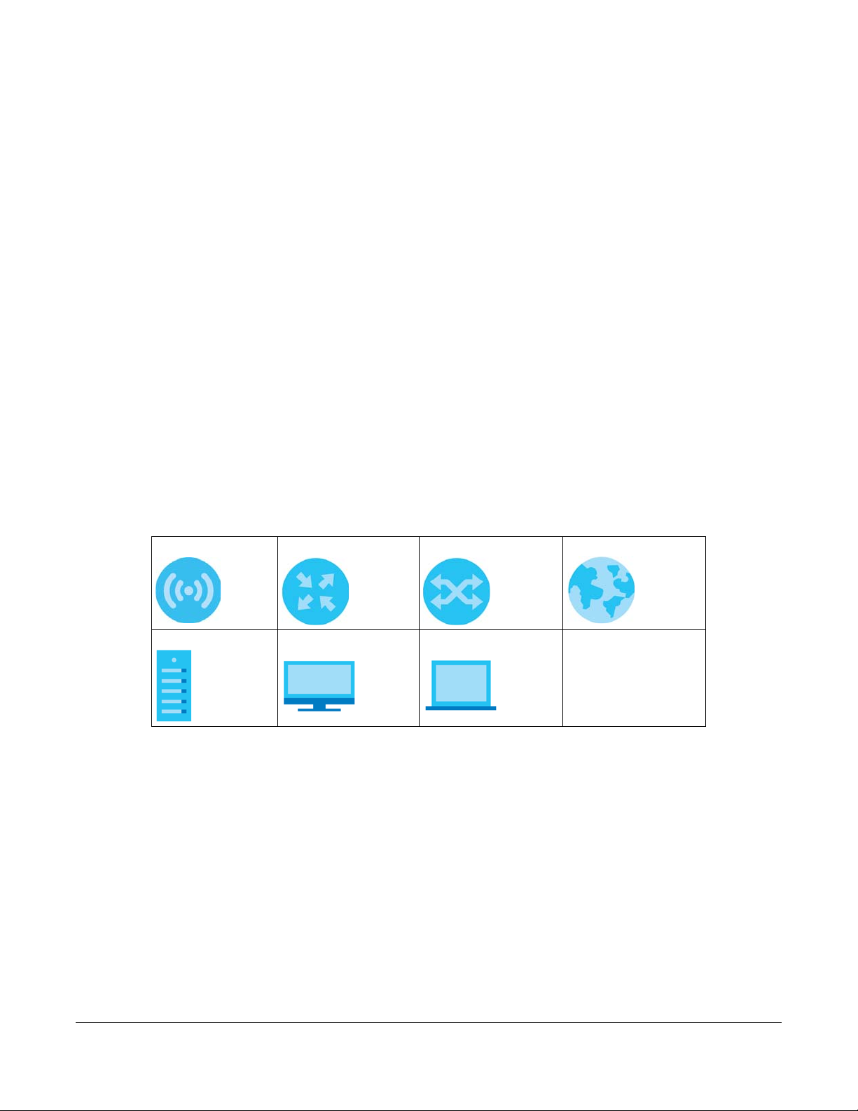
Icons Used in Figures
Figures in this guide may use the following generic icons. The WAP6804 icon is not an exact
representation of your device.
WAP6804 Router Switch Internet
Server Desktop Laptop
WAP6804 User’s Guide
3
Page 4

Contents Overview
Contents Overview
User’s Guide ........................................................................................................................................9
Introduction ........................................................................................................................................... 10
The Web Configurator ......................................................................................................................... 15
Modes .................................................................................................................................................... 22
Easy Mode ............................................................................................................................................. 24
Access Point Mode .............................................................................................................................. 28
Repeater Mode .................................................................................................................................... 33
Client Mode .......................................................................................................................................... 39
Tutorials .................................................................................................................................................. 43
Technical Reference ........................................................................................................................49
Monitor ................................................................................................................................................... 50
Network ................................................................................................................................................. 57
Wireless LAN .......................................................................................................................................... 60
AP Connection ..................................................................................................................................... 70
Maintenance ........................................................................................................................................ 75
Troubleshooting .................................................................................................................................... 82
WAP3205 v3 User’s Guide
4
Page 5

Table of Contents
Table of Contents
Document Conventions .................................................................. ....................................................3
Contents Overview .............................................................................................................................4
Table of Contents.................................................................................................................................5
Part I: User’s Guide............................................................................................ 9
Chapter 1
Introduction ........................................................................................................................................10
1.1 Overview ......................................................................................................................................... 10
1.2 Securing the WAP6804 ................................................................................................................... 10
1.3 Front Panel and LEDs ...................................................................................................................... 11
1.4 Rear Panel ....................................................................................................................................... 12
1.5 The WPS Button ............................................................................................................................... 13
1.5.1 Using the WPS Button ............................................................................................................ 14
1.6 The RESET Button ............................................................................................................................. 14
1.6.1 Using the RESET Button .......................................................................................................... 14
Chapter 2
The Web Configurator........................................................................................................................15
2.1 Overview ......................................................................................................................................... 15
2.2 Accessing the Web Configurator ................................................................................................. 15
2.3 Preparing your Computer to Access the Web Configurator .................................................... 16
2.3.1 Static IP Configuration in Microsoft Windows .................................................................... 17
2.3.2 Static IP Configuration in MAC OS X ................................................................................... 19
Chapter 3
Modes .................................................................................................................................................22
3.1 Overview ......................................................................................................................................... 22
3.1.1 Web Configurator Modes .................................................................................................... 22
3.1.2 Device Operating Modes .................................................................................................... 22
3.1.3 Changing Operating Mode ................................................................................................ 23
Chapter 4
Easy Mode..........................................................................................................................................24
4.1 Overview ......................................................................................................................................... 24
4.2 What You Can Do .......................................................................................................................... 25
WAP3205 v3 User’s Guide
5
Page 6

Table of Contents
4.3 Navigation Panel ............................................................................................................................ 25
4.4 Network Map .................................................................................................................................. 26
4.5 Status Screen in Easy Mode .......................................................................................................... 26
Chapter 5
Access Point Mode............................................................................................................................28
5.1 Overview ......................................................................................................................................... 28
5.1.1 What You Can Do ................................................................................................................. 28
5.2 Setting your WAP6804 to AP Mode .............................................................................................. 28
5.2.1 Status Screen (AP Mode) ..................................................................................................... 29
5.2.2 AP Navigation Panel ............................................................................................................. 31
Chapter 6
Repeater Mode..................................................................................................................................33
6.1 Overview ......................................................................................................................................... 33
6.1.1 What You Can Do ................................................................................................................. 33
6.2 Setting your WAP6804 to Repeater Mode ................................................................................... 33
6.2.1 Status Screen (Repeater Mode) ......................................................................................... 34
6.2.2 Repeater Navigation Panel ................................................................................................. 37
Chapter 7
Client Mode........................................................................................................................................39
7.1 Overview ......................................................................................................................................... 39
7.1.1 What You Can Do ................................................................................................................. 39
7.2 Setting your WAP6804 to Client Mode ......................................................................................... 39
7.2.1 Status Screen (Client Mode) ................................................................................................ 40
7.2.2 Client Navigation Panel ....................................................................................................... 41
Chapter 8
Tutorials...............................................................................................................................................43
8.1 Overview ......................................................................................................................................... 43
8.2 Connecting to the Internet from an Access Point ..................................................................... 43
8.3 Connecting to the WAP6804’s Wireless Network Using WPS ..................................................... 43
8.3.1 Push Button Configuration (PBC) ........................................................................................ 44
8.3.2 PIN Configuration .................................................................................................................. 45
8.4 Connecting the WAP6804 (in Repeater or Client Mode) to an AP .......................................... 46
8.4.1 Selecting an AP from an Automatically Detected List ..................................................... 47
8.4.2 Selecting an AP by Manually Entering Security Information ............................................ 47
Part II: Technical Reference........................................................................... 49
WAP3205 v3 User’s Guide
6
Page 7

Table of Contents
Chapter 9
Monitor................................................................................................................................................50
9.1 Overview ......................................................................................................................................... 50
9.2 What You Can Do .......................................................................................................................... 50
9.3 Log .................................................................................................................................................... 50
9.4 Wireless Monitor .......................................................................................................................... 51
9.5 WDS Monitor .................................................................................................................................... 54
9.6 MBSS Monitor ................................................................................................................................... 55
9.7 Multicast Monitor ............................................................................................................................ 56
Chapter 10
Network...............................................................................................................................................57
10.1 Overview ....................................................................................................................................... 57
10.2 What You Can Do ........................................................................................................................ 57
10.3 What You Need To Know ............................................................................................................ 57
10.4 Networking Screen ....................................................................................................................... 58
Chapter 11
Wireless LAN .......................................................................................................................................60
11.1 Overview ....................................................................................................................................... 60
11.2 What You Can Do ........................................................................................................................ 61
11.3 What You Should Know ............................................................................................................... 61
11.3.1 Wireless Security Overview ................................................................................................. 61
11.3.2 MAC Address Filter .............................................................................................................. 61
11.3.3 Encryption ............................................................................................................................ 62
11.3.4 WPS ....................................................................................................................................... 62
11.3.5 WDS ....................................................................................................................................... 62
11.4 Basic Wireless Network Screen ................................................................................................... 62
11.5 Advanced Wireless Network Screen ..........................................................................................64
11.6 WPS Screen ................................................................................................................................... 65
11.7 MAC Filter ...................................................................................................................................... 66
11.8 WDS Screen ................................................................................................................................... 67
11.9 MBSS Screen .................................................................................................................................. 68
Chapter 12
AP Connection...................................................................................................................................70
12.1 Overview ....................................................................................................................................... 70
12.2 What You Can Do ........................................................................................................................ 70
12.3 Basic/Station Screen .................................................................................................................... 70
12.4 Advance AP Connection Screen ............................................................................................... 71
12.5 AP List Screen ................................................................................................................................ 72
12.6 WPS Screen ................................................................................................................................... 74
WAP3205 v3 User’s Guide
7
Page 8

Table of Contents
Chapter 13
Maintenance......................................................................................................................................75
13.1 Overview ....................................................................................................................................... 75
13.2 What You Can Do ........................................................................................................................ 75
13.3 Password Screen .......................................................................................................................... 75
13.4 Time Screen ................................................................................................................................... 76
13.5 Firmware Upgrade Screen .......................................................................................................... 77
13.6 Telnet Screen ................................................................................................................................ 78
13.7 Restore Screen .............................................................................................................................. 79
13.7.1 Backup Configuration ........................................................................................................ 79
13.7.2 Restore Configuration ........................................................................................................ 80
13.7.3 Back to Factory Defaults .................................................................................................... 80
13.7.4 Restore but retain IP settings .............................................................................................. 80
13.8 Restart Screen ............................................................................................................................... 81
Chapter 14
Troubleshooting..................................................................................................................................82
14.1 Power, Hardware Connections, and LEDs ................................................................................. 82
14.2 WAP6804 Access and Login ........................................................................................................ 83
14.3 Internet Access ............................................................................................................................. 84
14.4 Resetting the WAP6804 to Its Factory Defaults ......................................................................... 85
14.5 Wireless Problems .......................................................................................................................... 85
Appendix A Wireless LANs ................................................................................................................ 86
Appendix B Customer Support ........................................................................................................ 99
Appendix C Legal Information ...................................................................................................... 105
Index.................................................................................................................................................113
WAP3205 v3 User’s Guide
8
Page 9

PART I
User’s Guide
9
Page 10
1.1 Overview
The WAP6804 extends the range of your existing wired network without additional wiring, providing easy
network access to mobile users. The WAP6804 is able to function in both 2.4GHz and 5GHz networks at
the same time.
You can set up the WAP6804 with other IEEE 802.11a/b/g/n/ac/an compatible devices in one of the
following device modes:
• Access Point
•Repeater
• Client
CHAPTER 1
Introduction
Use a (supported) web browser to manage the WAP6804. Menus slightly vary according to which mode
you’re using. See Chapter 3 on page 22 for more information on these modes.
1.2 Securing the WAP6804
Do the following things regularly to make the WAP6804 more secure and to manage the WAP6804 more
effectively.
• Change the password. Use a password that’s not easy to guess and that consists of different types of
characters, such as numbers and letters.
• Write down the password and put it in a safe place.
WAP6804 User’s Guide
10
Page 11

Chapter 1 Introduction
• Back up the configuration (and make sure you know how to restore it). Restoring an earlier working
configuration may be useful if the device becomes unstable or even crashes. If you forget your
password, you will have to reset the WAP6804 to its factory default settings. If you backed up an
earlier configuration file, you would not have to totally re-configure the WAP6804. You could simply
restore your last configuration.
1.3 Front Panel and LEDs
The following figure is the front panel of the WAP6804. Use the LEDs to determine if the WAP6804 is
behaving normally or if there are some problems on your network.
Figure 1 Front Panel
WAP6804 User’s Guide
11
Page 12
Chapter 1 Introduction
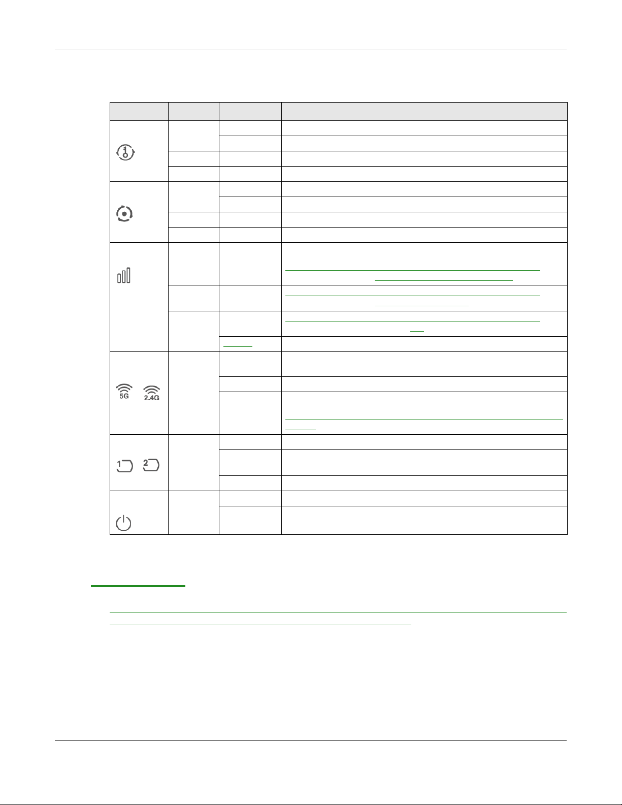
The following table describes the LEDs .
Table 1 Front Panel LEDs
LED COLOR STATUS DESCRIPTION
WPS Green On WPS is enabled or the WPS process completed successfully.
Blinking The WAP6804 is negotiating a WPS connection with a wireless client.
Red On The WPS process fails.
Off WPS is disabled.
Mode Green On The WAP6804 is working in AP Mode.
Blinking The WAP6804 is working in Repeater Mode.
Amber On The WAP6804 is working in Client Mode.
Off The WAP6804 has no activity.
Link Quality Green On In AP mode, the LED is always on.
In Client or Repeater mode, the WAP6804 is connecting to an AP
the transmission rate is between
Amber On In Client or Repeater mode, the WAP6804 is connecting to an AP and
Red On In Client or Repeater mode, the WAP6804 is connecting to an AP and
Blinking The WAP6804 has no wireless connection.
WLAN 5G/
2.4G
LAN1-2 Green On The WAP6804 has a successful 10/1000 Mbps Ethernet connection.
POWER Green On The WAP6804 is receiving power and functioning properly.
Green On The wireless interface of the WAP6804 is ready, but it is not sending/
Blinking The WAP6804 is sending/receiving data through the wireless LAN.
Off The wireless interface of the WAP6804 is not ready or has failed.
Blinking The WAP6804 is sending or receiving packets to/from an Ethernet
Off There is no connection on this port.
Off The WAP6804 is not receiving power.
the transmission rate is greater than
the transmission rate is less than 400
receiving data through the wireless LAN.
The 2.4 GHz wireless
default.
network on this port.
radio of the WAP6804 in client mode is disabled by
5000 Mbps and 400 Mbps.
5000 Mbps.
Mbps.
and
1.4 Rear Panel
The following figure is the rear panel of the WAP6804. Use the CL/RP/AP switch to change the WAP6804’s
operating mode. See Section 3.1.2 on page 22 for more information.
WAP6804 User’s Guide
12
Page 13
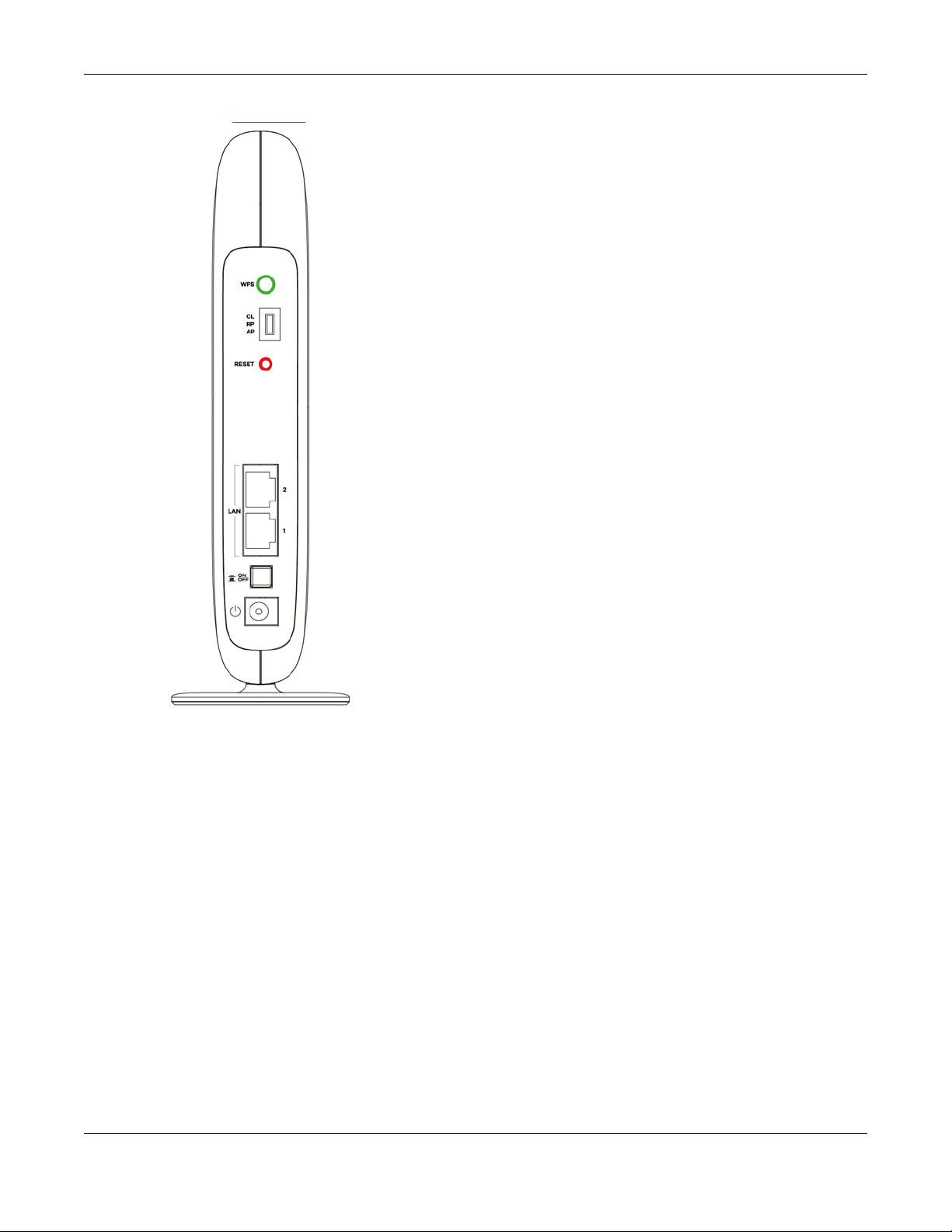
Figure 2 Rear Panel
Chapter 1 Introduction
1.5 The WPS Button
Your WAP6804 supports WiFi Protected Setup (WPS), which is an easy way to set up a secure wireless
network. WPS is an industry standard specification, defined by the Wi-Fi Alliance.
WPS allows you to quickly set up a wireless network with strong security, without having to configure
security settings manually. Each WPS connection works between two devices. Both devices must
support WPS (check each device’s documentation to make sure).
Depending on the devices you have, you can either press a button (recommended) on the device
itself, or in its configuration utility or enter a PIN (a unique Personal Identification Number that allows one
device to authenticate the other) in each of the two devices. When WPS is activated on a device, it has
two minutes to find another device that also has WPS activated. Then, the two devices connect and set
up a secure network by themselves.
The WPS button is located at the back panel of the WAP6804.
WAP6804 User’s Guide
13
Page 14

1.5.1 Using the WPS Button
1 Make sure the power LED is on (not blinking).
2 AP mode: Press the WPS button once. Press the WPS button on a WPS-aware client within range of the
WAP6804.
Client mode: Press the WPS button once. Press the WPS button on a WPS-aware AP or wireless router
within range of the WAP6804.
Repeater mode (Uplink): Press the WPS button once. Press the WPS button on a WPS-aware AP or
wireless router within range of the WAP6804.
Repeater mode (Downlink): Press the WPS button twice within three seconds. Press the WPS button on a
WPS-aware client within range of the WAP6804.
Note: You must activate WPS in the WAP6804 and in another wireless device within two
minutes of each other.
Note: With WPS, wireless clients can only connect to the 5GHz or 2.4GHz wireless network using
the first 5GHz or 2.4GHz SSID on the WAP6804 (in AP or repeater mode).
For more information on using WPS, see Section 8.3 on page 43.
Chapter 1 Introduction
1.6 The RESET Button
If you forget your password or IP address, or you cannot access the Web Configurator, you will need to
use the RESET button at the back of the WAP6804 to reload the factory-default configuration file. This
means that you will lose all configurations that you had previously saved, the password will be reset to
the default key on the device label
server.
1.6.1 Using the RESET Button
1 Make sure the power LED is on (not blinking).
2 Press the RESET button for one to five seconds to reboot the WAP6804.
3 Press the RESET button for longer than five seconds to set the WAP6804 back to its factory-default
configurations.
. The WAP6804 will be reset to obtain an IP address from a DHCP
WAP6804 User’s Guide
14
Page 15

2.1 Overview
This chapter describes how to access the WAP6804 Web Configurator and provides an overview of its
screens.
The Web Configurator is an HTML-based management interface that allows easy setup and
management of the WAP6804 via Internet browser. Use Internet Explorer 8.0 and later versions, Mozilla
Firefox, Google Chrome or Safari. The recommended screen resolution is 1024 by 768 pixels.
In order to use the Web Configurator you need to allow:
• Web browser pop-up windows from your device.
• JavaScript (enabled by default).
• Java permissions (enabled by default).
CHAPTER 2
The Web Configurator
Refer to Chapter 13 Troubleshooting to see how to make sure these functions are allowed in Internet
Explorer.
2.2 Accessing the Web Configurator
1 Make sure your WAP6804 hardware is properly connected and prepare your computer or computer
network to connect to the WAP6804 (refer to the Quick Start Guide).
2 Launch your web browser.
3 Type “http://zyxelsetup” (for Windows) or “http://zyxelsetup.local” (for Mac) as the website address to
access any of the modes.
The WAP6804 is a DHCP client by default. Alternatively, check the connected gateway for the
WAP6804's current IP address. Make sure your computer’s IP address is in the same subnet as the
WAP6804’s IP address. Type “http://(DHCP-assigned IP)” as the web address in your web browser.
If the WAP6804 is not connecting to a router or DHCP server, type the WAP6804’s default static IP
address. To access the AP mode, type “http://192.168.1.2”. To access the repeater mode, type “http://
192.168.1.5”. To access the client mode, type “http://192.168.1.10”. Your computer must be in the same
subnet in order to access this website address.You must give it a fixed IP address in the range between
192.168.1.11
and 192.168.1.254 (see Section 2.3 on page 16).
Note: Use the physical CL/RP/AP switch to change device operating mode before you
access its web configurator. See Chapter 3 on page 22 for more information.
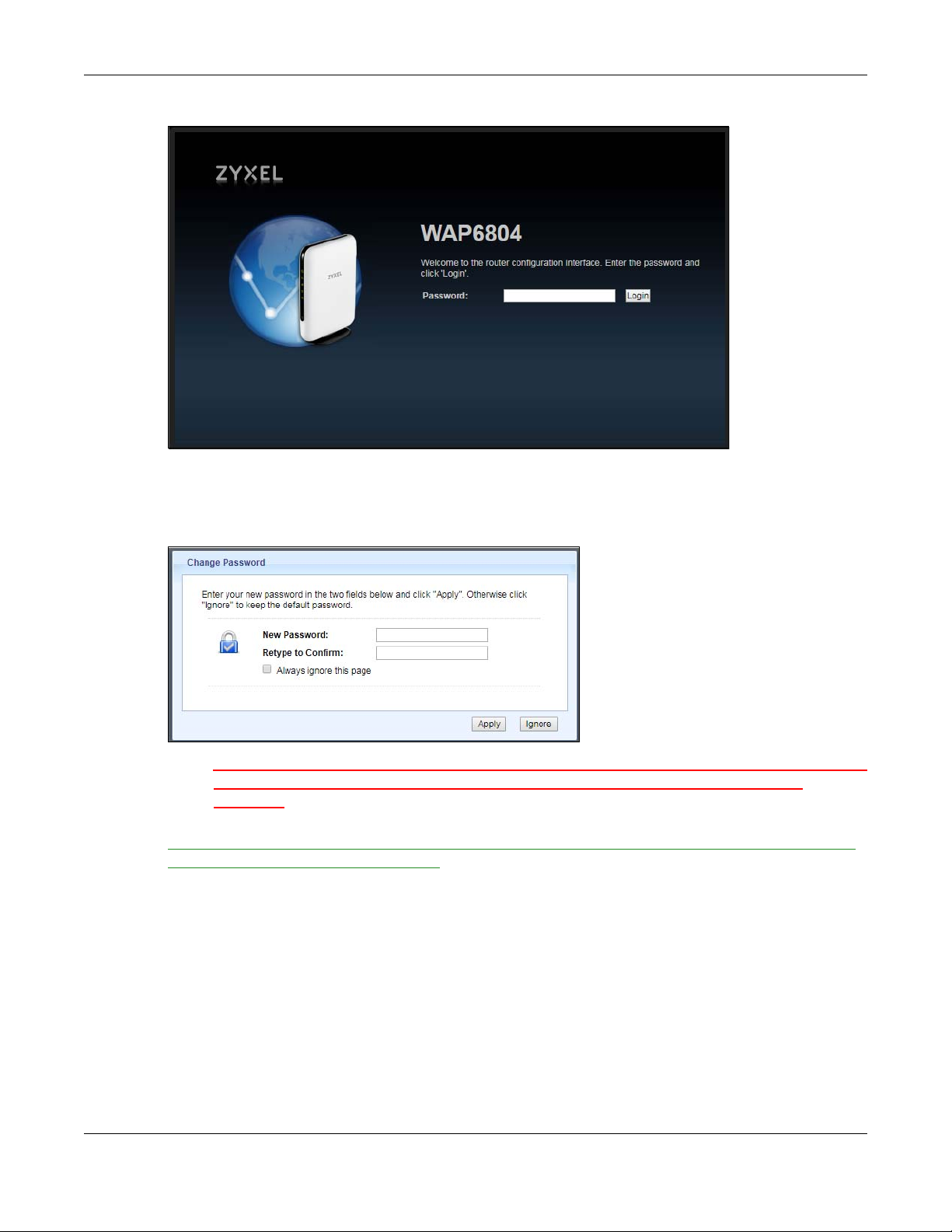
4 Type the password on the device label (default) as the password and click Login.
WAP6804 User’s Guide
15
Page 16
Chapter 2 The Web Configurator
Figure 3 Login Screen
5 You should see a screen asking you to change your password (highly recommended) as shown next.
Type a new password. Click Apply to save your changes. Click Ignore if you do not want to change the
password this time.
Figure 4 Change Password Screen
Note: For security reasons, the WAP6804 automatically logs you out if you do not use the web
configurator for five minutes (Default). Simply log back into the WAP6804 if this
happens.
Right after you log in, the easy mode network map screen is displayed. See Chapter 3 on page 22 for
more information about the easy mode.
2.3 Preparing your Computer to Access the Web Configurator
This section shows you how to assign a static IP address to your computer.
In order to access the web configurator your computer needs to be in the same subnet as the
WAP6804. Below you will find the steps to set a static IP on both Windows 7 (Section 2.3.1 on page 17)
and MAC OS X 10.11(Section 2.3.2 on page 19) operating systems. For other operating systems go to
Appendix C on page 108.
WAP6804 User’s Guide
16
Page 17
Chapter 2 The Web Configurator
2.3.1 Static IP Configuration in Microsoft Windows
Follow these steps to change your computer’s IP address in Windows 7 operating system.
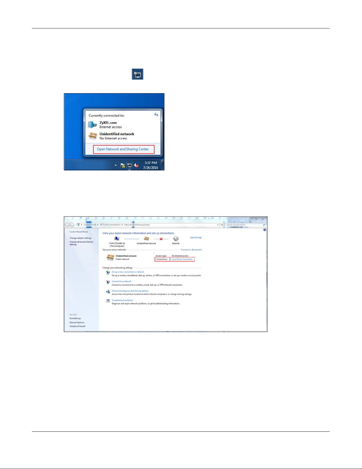
1 Click on the Network Icon located in the System Tray of your Task Bar. After you have clicked the
icon a small message window will appear, select Open Network and Sharing Center.
Note: You can also access the Network and Sharing Center by going to the Control Panel in
the Start Menu and clicking on Network and Sharing Center.
2 Once you have accessed the Network and Sharing Center, click on Local Area Connection to access
the adapter’s settings.
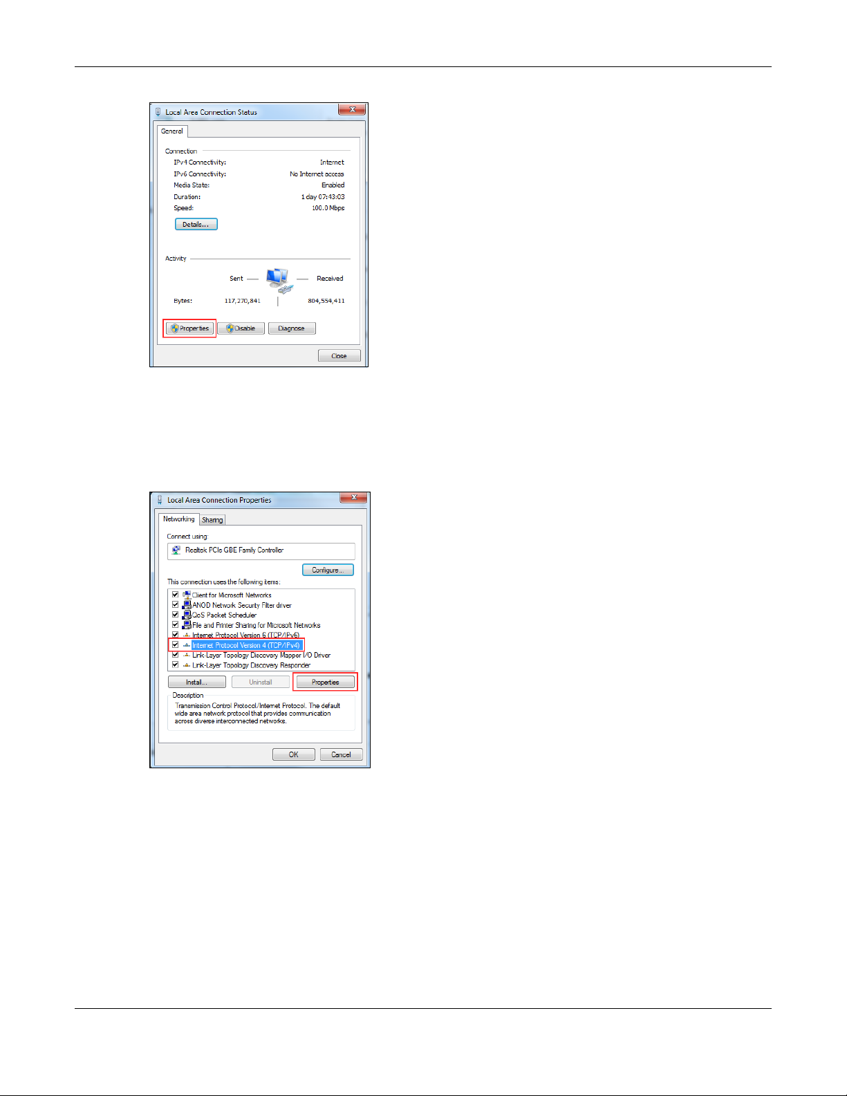
3 After accessing the connection’s general settings, click on the Properties button.
WAP6804 User’s Guide
17
Page 18
Chapter 2 The Web Configurator
Note: You can also access the adapter’s settings by clicking on Change adapter settings
located on the left side bar. Then right-clicking on the Local Area Connection icon and
selecting Properties.
4 In the connection’s properties select the Internet Protocol Version 4 (TCP/IPv4) item, then click on the
Properties button.
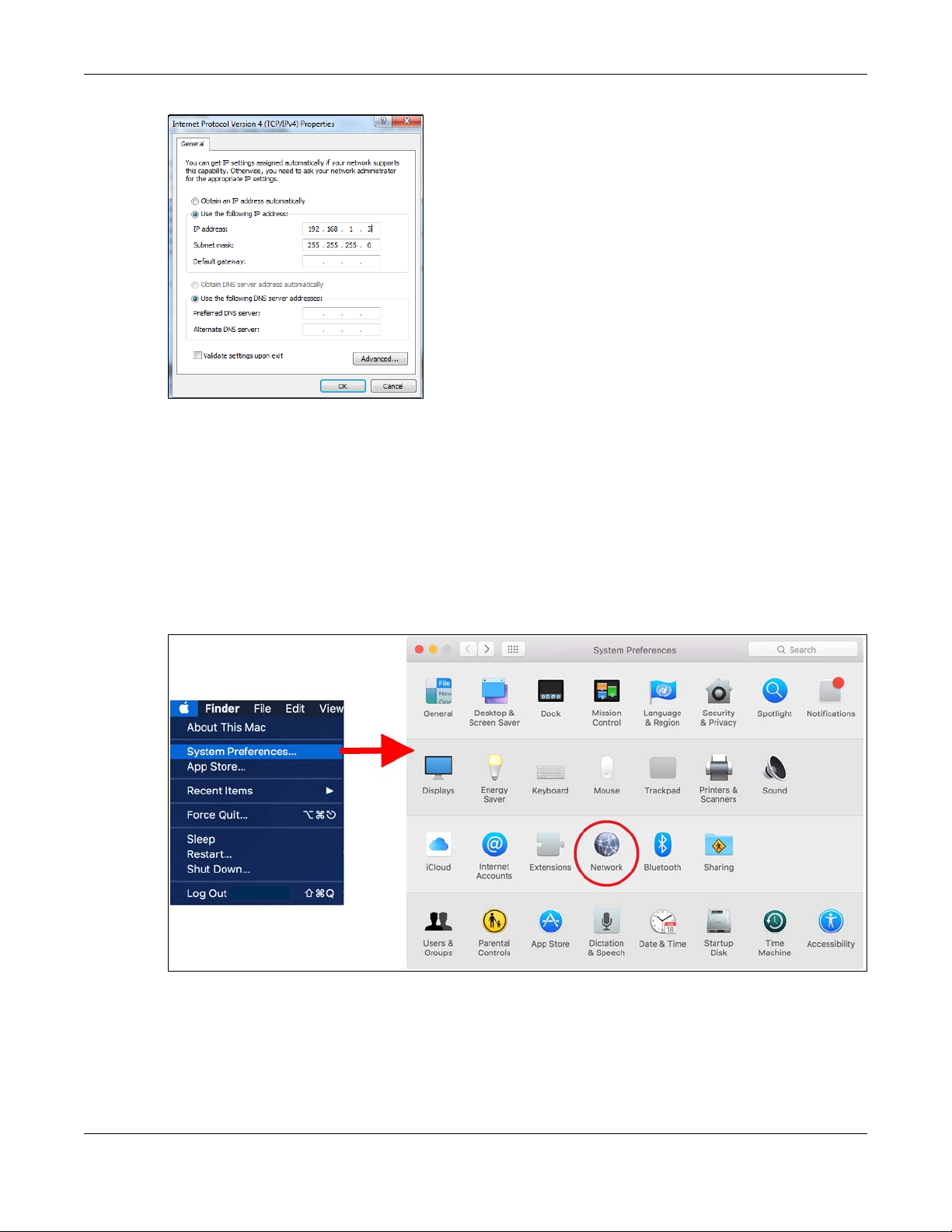
5 Once you have accessed the Internet Protocol Version 4 (TCP/IPv4) properties, click on the Use the
following IP address radio button and type your new IP address. Your computer must be in the same
subnet in order to access this website address.You must give it a fixed IP address in the range between
192.168.1.3 and 192.168.1.254. Then type 255.255.255.0 as your subnet mask, click OK to close the
Internet Protocol Version 4 (TCP/IPv4) Properties window. Then click OK to close the Local Area
Connection
WAP6804 User’s Guide
18
Page 19
Chapter 2 The Web Configurator
Note: After you have configured your WAP6804, you must remember to change your static IP
back to automatic to be able to access the Internet. If you want to change the IP
address to automatic (default) then repeat steps 1 to 4, for step 5 select the Obtain an
IP address automatically radio button, and click OK.
2.3.2 Static IP Configuration in MAC OS X
Follow these steps to change your computer’s IP address in MAC OS X 10.11 operating system.
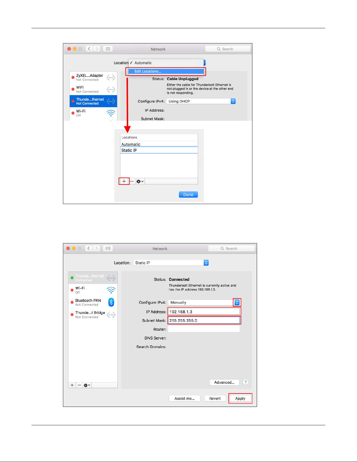
1 Open your System Preferences, then click on Network.
2 Once the Network screen is open, it is recommended you click on Location > Edit Locations to create a
new profile. Use the + button to add a new profile, in this case it is called Static IP. This will easily help you
change from static IP address to automatic.
WAP6804 User’s Guide
19
Page 20
Chapter 2 The Web Configurator
3 After creating your Static IP profile, make sure it is selected, then click on the Configure IPv4 scroll button
and select Manually. Then modify your IP Address, your computer must be in the same subnet in order to
access this website address.You must give it a fixed IP address in the range between 192.168.1.3 and
192.168.1.254. Then type 255.255.255.0 as your subnet mask, and click Apply to save your changes.
WAP6804 User’s Guide
20
Page 21

Chapter 2 The Web Configurator
Note: After you have configured your WAP6804, you must remember to change your static IP
back to obtaining it automatically to be able to access the Internet. If you want to
change the IP address to automatic (default) repeat step 1, then on Location select
Automatic or a different profile you have configured.
WAP6804 User’s Guide
21
Page 22

3.1 Overview
This chapter introduces the different modes available on your WAP6804. First, the term “mode” refers to
two things in this User’s Guide.
• Web Configurator mode. This refers to the Web Configurator screen you want to use for editing
WAP6804 features.
• Device mode. This is the operating mode of your WAP6804, or simply how the WAP6804 is being used
in the network.
3.1.1 Web Configurator Modes
This refers to the configuration interface of the Web Configurator, which has two modes:
CHAPTER 3
Modes
• Easy Mode. The Web Configurator shows this mode by default. Refer to Chapter 4 on page 24 for
more information on the screens in this mode. This shows how the WAP6804’s network is currently laid
out.
• Expert Mode. Advanced users can change to this mode to customize all the functions of the
WAP6804. Click Expert Mode after logging into the Web Configurator. The User’s Guide Chapter 2 on
page 15 through Chapter 13 on page 75 discusses the screens in this mode.
3.1.2 Device Operating Modes
This refers to the operating mode of the WAP6804, which can act as a:
• Access Point: Use this mode if you already have a router in your network and you want to set up a
wireless network and bridge the wired and wireless connections on the WAP6804.
• Repeater: In this mode, the WAP6804 can be an access point and a wireless client at the same time.
Use this mode if there is an existing wireless router or access point in your network and you want the
WAP6804 to wirelessly relay communications from its wireless clients to the access point.
• Client: Use this mode to have the WAP6804 work only as a wireless client if there is an existing wireless
router or access point in the network to which you want to connect your local network wirelessly. In
this mode, you should know the SSID and wireless security details of the access point to which you
want to connect.
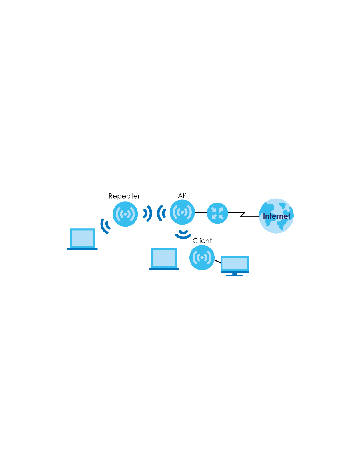
The following figure is an illustration of the device operating modes of the WAP6804.
WAP6804 User’s Guide
22
Page 23
Chapter 3 Modes
Figure 5 Device Operating Mode Example
Note: Choose your device mode carefully to avoid having to change it later.
3.1.3 Changing Operating Mode
Push the CL/RP/AP switch on the WAP6804’s side panel to the AP position to have the WAP6804 act as
an access point. Push the switch to the RP position to have the WAP6804 work as a repeater. Otherwise,
push the switch to the CL position to have the WAP6804 work as a wireless client.
Note: The WAP6804 restarts automatically after you change operating modes.
WAP6804 User’s Guide
23
Page 24
4.1 Overview
The Web Configurator is set to Easy Mode by default. This mode is useful to users by visualizing their
networks’ layout. You can view details about the devices connected to your WAP6804 and their status.
When you log in to the Web Configurator, the following screen opens.
Figure 6 Easy Mode: Network Map
CHAPTER 4
Easy Mode
Click Status to open the following screen.
WAP6804 User’s Guide
24
Page 25
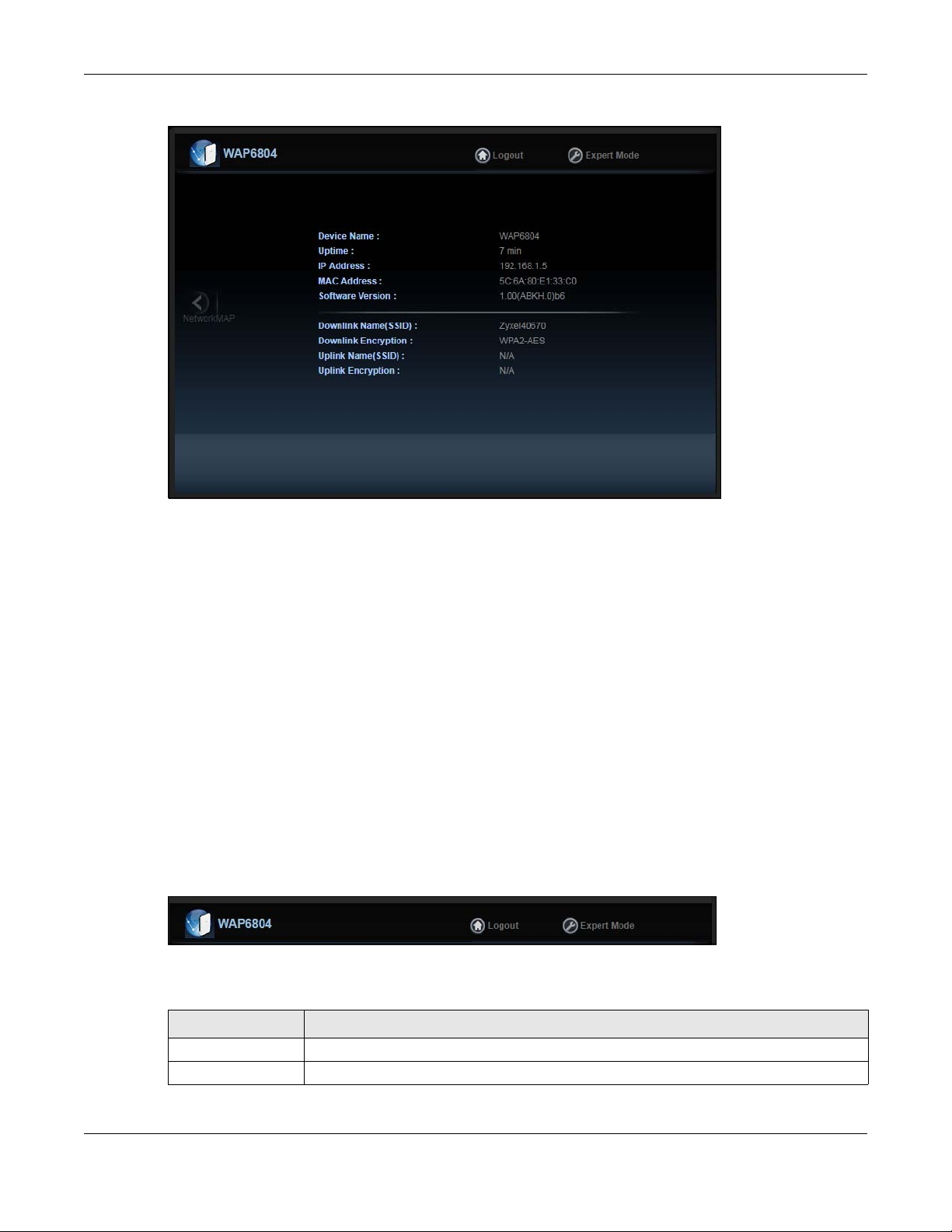
Figure 7 Easy Mode: Status Screen
Chapter 4 Easy Mode
4.2 What You Can Do
You can do the following in this mode:
• Use the Navigation Panel to opt out of the Easy mode.
• Use the Network Map screen to check if your WAP6804 can ping the gateway and whether it is
connected to the Internet.
• Use the Status screen to view read-only information about the WAP6804, including the WAN IP, MAC
address of the WAP6804 and the software version.
4.3 Navigation Panel
Use this navigation panel to opt out of the Easy mode.
Figure 8 Navigation Panel
The following table describes the labels in this screen.
Table 2 Navigation Panel
LABEL DESCRIPTION
Logout Click this to end the Web Configurator session.
Expert Mode Click this to change to Expert Mode and customize features of the WAP6804.
WAP6804 User’s Guide
25
Page 26
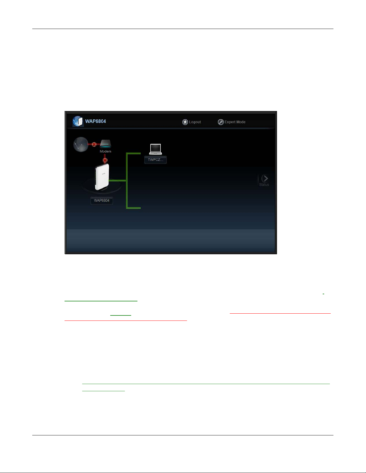
4.4 Network Map
Note: Don’t worry if the Network Map does not display in your web browser. This feature may
not be supported by your system. You can still configure your WAP6804’s features in the
Expert Mode.
When you log in to the Web Configurator, the Network Map is shown as follows.
Figure 9 Network Map
Chapter 4 Easy Mode
The line connecting the WAP6804 to the gateway becomes green when the WAP6804 is able to ping
the gateway. It becomes red when the ping initiating from the WAP6804 does not get a response from
the gateway. The same rule applies to the line connecting the gateway to the Internet.
You can also view the devices (represented by icons indicating the kind of network device, such as
Android device, iOS device or Windows OS) connected to the WAP6804, including those connecting
wirelessly. Right-click on the Refresh button located on the WAP6804 icon to refresh the network map.
Click on a device’s name
the WAP6804, or view the parental control rules.
to view information about the device, block or allow the device’s access to
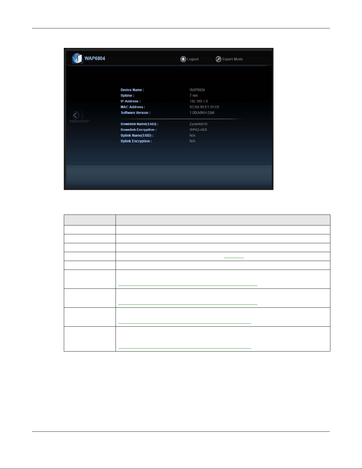
4.5 Status Screen in Easy Mode
In the Network Map, click Status to view read-only information about the WAP6804.
Note: The Status Screen displayed in Easy Mode varies according to the operating mode of
your WAP6804.
WAP6804 User’s Guide
26
Page 27
Chapter 4 Easy Mode
Figure 10 Status Screen in Easy Mode (Repeater Mode)
The following table describes the labels in this screen.
Table 3 Status Screen in Easy Mode
LABEL DESCRIPTION
Device Name This is the WAP6804’s model name.
Uptime This displays the time in minutes the WAP6804’s system has been working.
IP Address This shows the LAN port’s IP address.
MAC Address This shows the MAC address of the WAP6804’s LAN port
Software Version This is the firmware version.
Downlink Name
(SSID)
Downlink Encryption This shows the data encryption method the WAP6804 uses for the wireless connection.
Uplink Name (SSID) This shows the descriptive name of the wireless LAN to which the WAP6804 is connected.
Uplink Encryption This shows the data encryption method the connected access point uses for the wireless
This shows a descriptive name used to identify the WAP6804 in the wireless LAN.
This field is not available when the WAP6804 is in client mode.
This field is not available when the WAP6804 is in client mode.
This field is not available when the WAP6804 is in AP mode.
connection.
This field is not available when the WAP6804 is in AP mode.
.
WAP6804 User’s Guide
27
Page 28
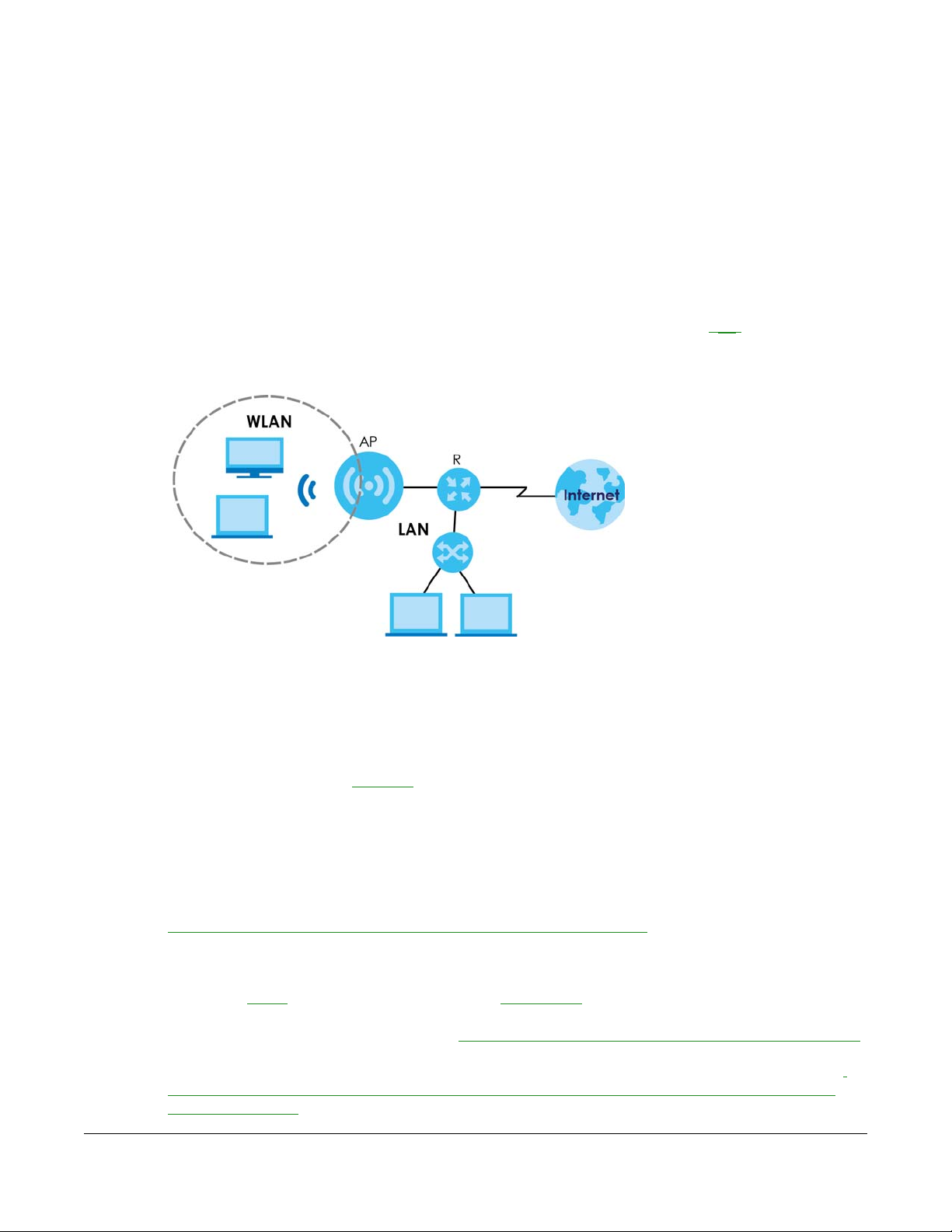
5.1 Overview
The WAP6804 is set to access point mode by default. In this mode your WAP6804 (AP) bridges a wired
network (LAN) and wireless LAN (WLAN) in the same subnet. See the figure below for an example.
Figure 11 Access Point Mode
CHAPTER 5
Access Point Mode
5.1.1 What You Can Do
• Use the Status screen (Section 5.2.1 on page 29) to view read-only information about your WAP6804.
• Use the Network > Networking screen (Chapter 10 on page 57) to set the IP address for your WAP6804
acting as an access point.
• Use the Wireless Network 5G/2.4G
and wireless security between the wireless clients and the WAP6804.
screens (Chapter 11 on page 60) to configure the wireless settings
5.2 Setting your WAP6804 to AP Mode
1 To use your WAP6804 as an access point, see Section 3.1.3 on page 23.
2 Connect your computer to the LAN port of the WAP6804.
3 The default static
your computer an IP address, so you must give it a fixed IP address in the range between 192.168.1.3
and 192.168.1.254 (Section 2.3 on page 16) if the
4 After you’ve set your computer’s IP address, open a web browser such as Internet Explorer and type
“http://zyxelsetup” (for Windows), http://zyxelsetup.local” (for Mac), “http://(DHCP-assigned IP), or
“http://192.168.1.2” as the web address in your web browser.
LAN IP address of the WAP6804 in AP mode is 192.168.1.2. The WAP6804 cannot assign
WAP6804 is not connected to a router or DHCP server.
WAP6804 User’s Guide
28
Page 29
Chapter 5 Access Point Mode
5 Log into the Web Configurator. See the Section 2.2 on page 15 for instructions on how to do this.
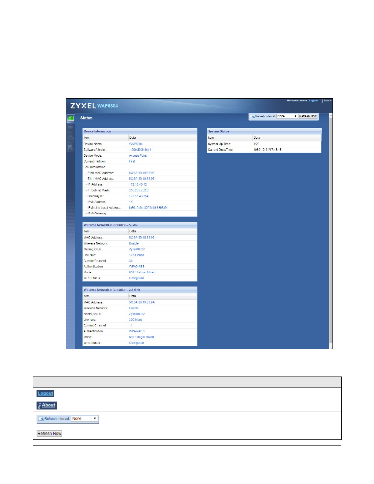
5.2.1 Status Screen (AP Mode)
Click on Status. The screen below shows the status screen in AP Mode.
Figure 12 Status Screen (AP Mode)
The following table describes the icons shown in the Status screen.
Table 4 Status Screen Icon Key (AP Mode)
ICON DESCRIPTION
Click this at any time to exit the Web Configurator.
Click this icon to view copyright and a link for related product information.
Select a number of seconds or None from the drop-down list box to refresh all screen statistics
automatically at the end of every time interval or to not refresh the screen statistics.
Click this button to refresh the status screen statistics.
WAP6804 User’s Guide
29
Page 30
Chapter 5 Access Point Mode
Table 4 Status Screen Icon Key (AP Mode) (continued)
ICON DESCRIPTION
Click this icon to see the Status page. The information in this screen depends on the device mode
you select.
Click this icon to see the Monitor navigation menu.
Click this icon to see the Configuration navigation menu.
Click this icon to see the Maintenance navigation menu.
The following table describes the labels shown in the Status screen.
Table 5 Status Screen (AP Mode)
LABEL DESCRIPTION
Device Information
Device Name This is the WAP6804’s model name.
Software Version This is the firmware version and the date created.
Device Mode This is the device mode (Section 3.1.2 on page 22) to which the WAP6804 is set - Access Point
Uptime (Min)
Current Partition This shows which partition the WAP6804 uses. The WAP6804 has two partitions and supports dual
LAN Information
Eth0 MAC Address This shows the MAC Address of the WAP6804’s first Ethernet LAN port.
Eth1 MAC Address This shows the MAC Address of the WAP6804’s second Ethernet LAN port.
IP Address This shows the LAN port’s IP address.
IP Subnet Mask This shows the LAN port’s subnet mask.
Gateway IP
IPv6 Address This shows the LAN port’s IPv6 address.
IPv6 Link Local Address This shows the LAN port’s current IPv6 link-local address.
IPv6 Gateway This shows the LAN port’s gateway IPv6 address.
Wireless Network Information - 5 GHz/2.4 GHz
MAC Address This shows the MAC address of the WAP6804’s wireless interface.
Wireless Network This shows if the wireless network is enabled or disabled.
Name (SSID) This shows a descriptive name used to identify the WAP6804 in the wireless LAN.
Link Rate (Mbps) This shows the rate at which data is transferred across the wireless network.
Current Channel This shows the channel number which you select manually or the WAP6804 automatically scans
Authentication This shows the data encryption method the WAP6804 uses for the wireless connection.
Mode This shows the wireless standard the WAP6804 uses.
WPS Status This displays Configured when the WPS has been set up.
System Status
System Up Time This is the total time the WAP6804 has been on.
Current Date/Time This field displays your WAP6804’s present date and time.
Mode.
This displays the time in minutes the WAP6804’s system has been working.
image function.
This shows the LAN port’s gateway IP address.
and selects.
This displays Unconfigured if the WPS has not been set up.
WAP6804 User’s Guide
30
Page 31

5.2.2 AP Navigation Panel
Use the menu in the navigation panel to configure WAP6804 features in AP Mode.
The following screen and table show the features you can configure in AP Mode.
Figure 13 Menu: Access Point Mode
The following table describes the sub-menus.
Table 6 Navigation Panel: Access Point Mode
LINK TAB FUNCTION
Status Status This screen shows the WAP6804’s general device, system status information.
MONITOR
Monitor
Log View Log Use this screen to view the list of activities recorded by your WAP6804.
Wireless
Monitor
WDS Monitor WDS Monitor Use this screen to view the Wireless Distribution System (WDS) summary.
MBSS Monitor MBSS Monitor Use this screen to view a summary of the Multiple Basic Server Sets (MBSS)
Multicast
Monitor
CONFIGURATION
Networking
Network Networking Use this screen to configure the WAP6804’s LAN IPv4 and IPv6 addresses.
Wireless
Network 5G
Wireless
Network 2.4G
Wireless
Monitor
Multicast
Monitor
Basic Use this screen to configure general wireless LAN settings.
Advanced Use this screen to configure advanced wireless settings.
WPS Use this screen to enable and configure WPS on your WAP6804.
MAC Filter Use this screen to configure the WAP6804 to block access to devices or block
WDS Use this screen to set up Wireless Distribution System (WDS) on your WAP6804.
MBSS Use this screen to configure multiple BSSs on the WAP6804.
Basic Use this screen to configure general wireless LAN settings.
Advanced Use this screen to configure advanced wireless settings.
WPS Use this screen to enable and configure WPS on your WAP6804.
MAC Filter Use this screen to configure the WAP6804 to block access to devices or block
MBSS Use this screen to configure multiple BSSs on the WAP6804.
Chapter 5 Access Point Mode
Use this screen to view the wireless summary currently associated to the
WAP6804.
available on the WAP6804. The MBSS allows you to use one access point to
provide several Basic Serve Sets (BSS) simultaneously.
Use this screen to view the multicast group information.
the devices from accessing the WAP6804.
the devices from accessing the WAP6804.
WAP6804 User’s Guide
31
Page 32

Chapter 5 Access Point Mode
Table 6 Navigation Panel: Access Point Mode
LINK TAB FUNCTION
MAINTENANCE
Password Password
Setup
Time Time Setup Use this screen to change your WAP6804’s time and date.
Firmware
Upgrade
Telnet Telnet Use this screen to enable or disable Telnet. Telnet allows you to access the
Restore Restore Use this screen to backup and restore the configuration or reset your WAP6804
Restart Restart Use this screen to reboot the WAP6804 without turning the power off.
Firmware
Upgrade
Use this screen to change the password of your WAP6804.
Use this screen to upload firmware to your WAP6804.
WAP6804’s command line interface.
to the factory defaults.
WAP6804 User’s Guide
32
Page 33

6.1 Overview
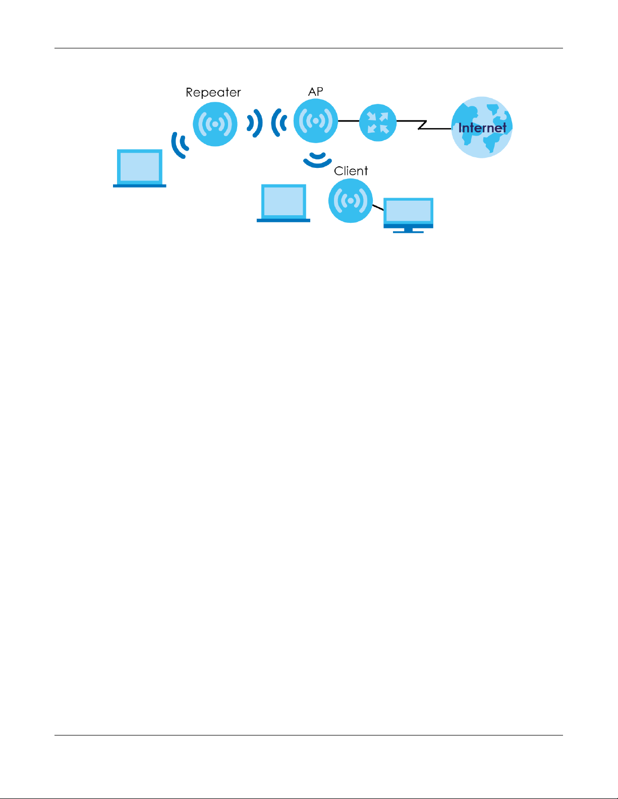
In repeater mode, your WAP6804 can act as an access point and wireless client at the same time. The
WAP6804 can connect to an existing network through another access point and also lets wireless clients
connect to the network through it. This helps you expand wireless coverage when you have an access
point or wireless router already in your network.
In the example below, the WAP6804 (A) is configured as a repeater. It has three clients that want to
connect to the Internet. The WAP6804 wirelessly connects to the available access point (B).
Figure 14 Repeater Mode
CHAPTER 6
Repeater Mode
After the WAP6804 and the access point connect, the WAP6804 acquires its IP address from the access
point. The clients of the WAP6804 can now surf the Internet.
6.1.1 What You Can Do
• Use the Status screen (Section 6.2.1 on page 34) to view read-only information about your WAP6804.
• Use the Network screen (Chapter 10 on page 57) to set the IP address for your WAP6804 acting as an
access point.
• Use the Wireless Network 5G/2.4G screens (Chapter 11 on page 60) to configure the wireless settings
and wireless security between the wireless clients and the WAP6804.
• Use the
transmission range and connect to an AP.
AP Connection screens (Section 10.6 on page 66) to scan for available access points within
6.2 Setting your WAP6804 to Repeater Mode
1 To use your WAP6804 as a repeater, see Section 3.1.3 on page 23.
WAP6804 User’s Guide
33
Page 34

Chapter 6 Repeater Mode
2 Connect your computer to the LAN port of the WAP6804.
3 The default static
computer a fixed IP address in the range between 192.168.1.6
16) if the
4 After you’ve set your computer’s IP address, open a web browser such as Internet Explorer and type
“http://zyxelsetup” (for Windows), http://zyxelsetup.local” (for Mac), “http://(DHCP-assigned IP), or
“http://192.168.1.5” as the web address in your web browser.
5 Log into the Web Configurator. See the Section 2.2 on page 15 for instructions on how to do this.
WAP6804 is not connected to a router or DHCP server.
LAN IP address of the WAP6804 in repeater mode is 192.168.1.5. You must give your
6.2.1 Status Screen (Repeater Mode)
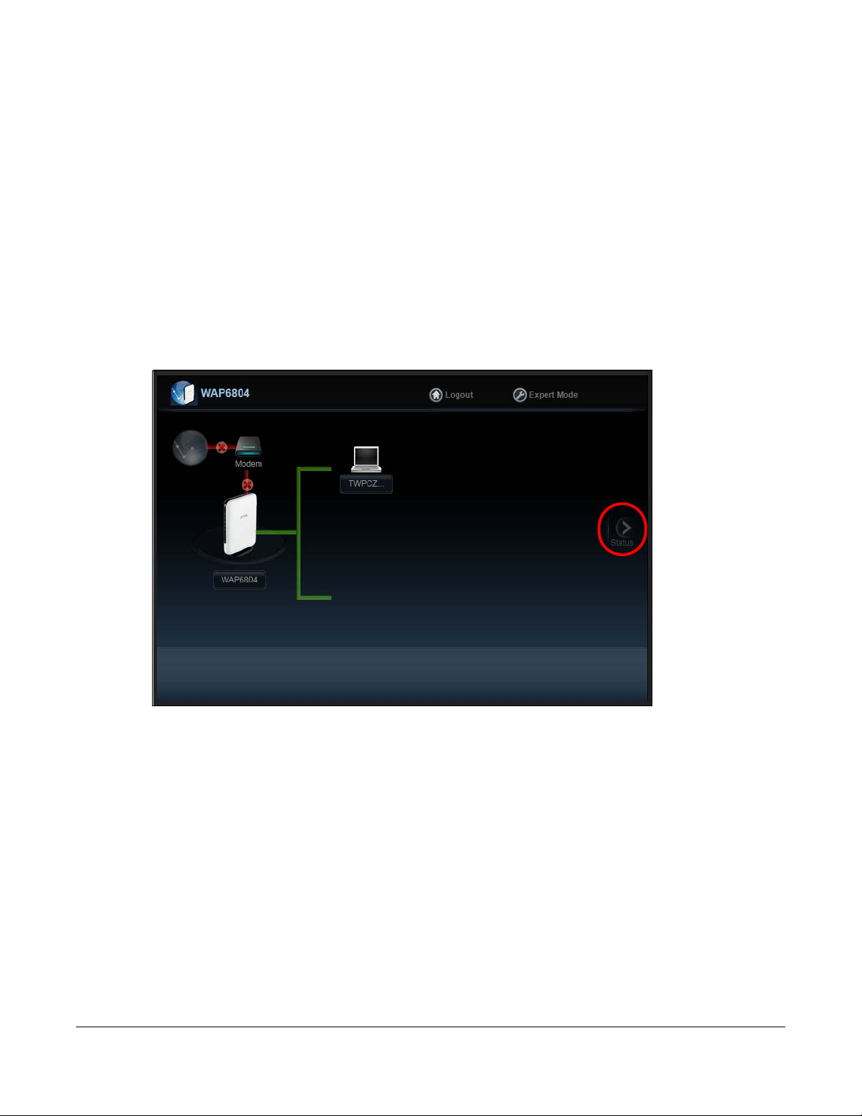
Click on Status. The screen below shows the status screen in Repeater mode.
and 192.168.1.254 (Section 2.3 on page
WAP6804 User’s Guide
34
Page 35

Chapter 6 Repeater Mode
Figure 15 Status Screen (Repeater Mode)
The following table describes the icons shown in the Status screen.
Table 7 Status Screen Icon Key (Repeater Mode)
ICON DESCRIPTION
Click this at any time to exit the Web Configurator.
Click this icon to view copyright and a link for related product information.
Select a number of seconds or None from the drop-down list box to refresh all screen statistics
automatically at the end of every time interval or to not refresh the screen statistics.
Click this button to refresh the status screen statistics.
WAP6804 User’s Guide
35
Page 36

Chapter 6 Repeater Mode
Table 7 Status Screen Icon Key (Repeater Mode) (continued)
ICON DESCRIPTION
Click this icon to see the Status page. The information in this screen depends on the device mode
you select.
Click this icon to see the Monitor navigation menu.
Click this icon to see the Configuration navigation menu.
Click this icon to see the Maintenance navigation menu.
The following table describes the labels shown in the Status screen.
Table 8 Status Screen (Repeater Mode)
LABEL DESCRIPTION
Device Information
Device Name This is the WAP6804’s model name.
Software Version This is the firmware version and the date created.
Device Mode This is the device mode (Section 3.1.2 on page 22) to which the WAP6804 is set - Repeater Mode.
Current Partition This shows which partition the WAP6804 uses. The WAP6804 has two partitions and supports dual
LAN Information
Eth0 MAC Address This shows the MAC Address of the WAP6804’s first Ethernet LAN port.
Eth1 MAC Address This shows the MAC Address of the WAP6804’s second Ethernet LAN port.
IP Address This shows the LAN port’s IP address.
IP Subnet Mask This shows the LAN port’s subnet mask.
Gateway IP This shows the LAN port’s gateway IP address.
IPv6 Address This shows the LAN port’s IPv6 address.
IPv6 Link Local Address This shows the LAN port’s current IPv6 link-local address.
IPv6 Gateway This shows the LAN port’s gateway IPv6 address.
AP Connection Status
MAC Address This shows the MAC address of the access point to which the WAP6804 is connected.
Name (SSID) This shows the descriptive name of the wireless LAN to which the WAP6804 is connected.
Channel This shows the channel number which you select manually or the WAP6804 automatically scans
Authentication This shows the data encryption method the access point uses for the wireless connection.
Status This shows if the WAP6804 is connected or disconnected from an access point.
Wireless Network Information - 5 GHz/2.4 GHz
MAC Address This shows the MAC address of the WAP6804’s wireless interface.
Wireless Network This shows if the wireless network is enabled or disabled.
Name (SSID) This shows a descriptive name used to identify the WAP6804 in the wireless LAN.
Link Rate (Mbps) This shows the rate at which data is transferred across the wireless network.
Current Channel This shows the channel number which you select manually or the WAP6804 automatically scans
Authentication This shows the data encryption method the WAP6804 uses for the wireless connection.
Mode This shows the wireless standard the WAP6804 uses.
image function.
and selects.
and selects.
WAP6804 User’s Guide
36
Page 37

Chapter 6 Repeater Mode
Table 8 Status Screen (Repeater Mode)
LABEL DESCRIPTION
WPS Status This displays Configured when the WPS has been set up.
This displays Unconfigured if the WPS has not been set up.
System Status
System Up Time This is the total time the WAP6804 has been on.
Current Date/Time This field displays your WAP6804’s present date and time.
6.2.2 Repeater Navigation Panel
Use the menu in the navigation panel to configure WAP6804 features in Repeater Mode.
The following screen and table show the features you can configure in Repeater Mode.
Figure 16 Menu: Repeater Mode
The following table describes the sub-menus.
Table 9 Navigation Panel: Repeater Mode
LINK TAB FUNCTION
Status Status This screen shows the WAP6804’s general device, system status information.
MONITOR
Monitor
Log View Log Use this screen to view the list of activities recorded by your WAP6804.
Wireless
Monitor
MBSS Monitor MBSS Monitor Use this screen to view a summary of the Multiple Basic Server Sets (MBSS)
Multicast
Monitor
CONFIGURATION
Networking
Network Networking Use this screen to configure the WAP6804’s LAN IPv4 and IPv6 addresses.
Wireless
Monitor
Multicast
Monitor
Use this screen to view the wireless summary currently associated to the
WAP6804.
available on the WAP6804. The MBSS allows you to use one access point to
provide several Basic Serve Sets (BSS) simultaneously.
Use this screen to view the multicast group information.
WAP6804 User’s Guide
37
Page 38

Chapter 6 Repeater Mode
Table 9 Navigation Panel: Repeater Mode
LINK TAB FUNCTION
Wireless
Network 5G
AP
Connection
Wireless
Network 2.4G
MAINTENANCE
Password Password
Time Time Setup Use this screen to change your WAP6804’s time and date.
Firmware
Upgrade
Telnet Telnet Use this screen to enable or disable Telnet. Telnet allows you to access the
Restore Restore Use this screen to backup and restore the configuration or reset your WAP6804
Restart Restart Use this screen to reboot the WAP6804 without turning the power off.
Basic Use this screen to configure general wireless LAN settings.
Advanced Use this screen to configure advanced wireless settings.
WPS Use this screen to enable and configure WPS on your WAP6804.
MAC Filter Use this screen to configure the WAP6804 to block access to devices or block
the devices from accessing the WAP6804.
WDS Use this screen to set up Wireless Distribution System (WDS) on your WAP6804.
MBSS Use this screen to configure multiple BSSs on the WAP6804.
Station Use this screen to enter the SSID and configure the wireless security between
the WAP6804 and the wireless network to which you want to connect.
AP List Use this screen to scan the wireless networks in the WAP6804’s area.
WPS Use this screen to quickly set up a wireless network with strong security
Basic Use this screen to configure general wireless LAN settings.
Advanced Use this screen to configure advanced wireless settings.
WPS Use this screen to enable and configure WPS on your WAP6804.
MAC Filter Use this screen to configure the WAP6804 to block access to devices or block
MBSS Use this screen to configure multiple BSSs on the WAP6804.
Setup
Firmware
Upgrade
between your WAP6804 and the AP.
the devices from accessing the WAP6804.
Use this screen to change the password of your WAP6804.
Use this screen to upload firmware to your WAP6804.
WAP6804’s command line interface.
to the factory defaults.
WAP6804 User’s Guide
38
Page 39

7.1 Overview
A
B
Your WAP6804 can act as a wireless client. In wireless client mode, it can connect to an existing network
via an access point. Use this mode if you already have an access point or wireless router in your network.
In the example below, one WAP6804 (A) is configured as a wireless client and another is used as an
access point (B). The WAP6804 has two clients that need to connect to the Internet.
wirelessly connects to the available access point (B).
Figure 17 Wireless Client Mode
CHAPTER 7
Client Mode
The WAP6804
After the WAP6804 in client mode and the access point connect, the WAP6804 acquires its WAN IP
address from the access point. You can now surf the Internet from the computer that is connected to
the WAP6804 in client mode.
7.1.1 What You Can Do
• Use the Status screen (Section 7.2.1 on page 40) to view read-only information about your WAP6804.
• Use the Network screen (Chapter 10 on page 57) to set the IP address for your WAP6804 acting as an
access point.
• Use the
transmission range and connect to an AP.
AP Connection screens (Section 10.6 on page 66) to scan for available access points within
7.2 Setting your WAP6804 to Client Mode
1 To use your WAP6804 as a wireless client, see Section 3.1.3 on page 23.
2 Connect your computer to the LAN port of the WAP6804.
3 The default static
a fixed IP address in the range between 192.168.1.11
WAP6804 is not connected to a router or DHCP server.
LAN IP address of the WAP6804 in client mode is 192.168.1.10. You give your computer
and 192.168.1.254 (Section 2.3 on page 16) if the
WAP6804 User’s Guide
39
Page 40

Chapter 7 Client Mode
4 After you’ve set your computer’s IP address, open a web browser such as Internet Explorer and type
“http://zyxelsetup” (for Windows), http://zyxelsetup.local” (for Mac), “http://(DHCP-assigned IP), or
“http://192.168.1.5” as the web address in your web browser.
5 Log into the Web Configurator. See the Chapter 2 on page 15 for instructions on how to do this.
7.2.1 Status Screen (Client Mode)
Click on Status. The screen below shows the status screen in Client mode.
Figure 18 Status Screen (Client Mode)
The following table describes the icons shown in the Status screen.
Table 10 Status Screen Icon Key (Client Mode)
ICON DESCRIPTION
Click this at any time to exit the Web Configurator.
Click this icon to view copyright and a link for related product information.
Select a number of seconds or None from the drop-down list box to refresh all screen statistics
automatically at the end of every time interval or to not refresh the screen statistics.
Click this button to refresh the status screen statistics.
Click this icon to see the Status page. The information in this screen depends on the device mode
you select.
Click this icon to see the Monitor navigation menu.
WAP6804 User’s Guide
40
Page 41

Chapter 7 Client Mode
Table 10 Status Screen Icon Key (Client Mode) (continued)
ICON DESCRIPTION
Click this icon to see the Configuration navigation menu.
Click this icon to see the Maintenance navigation menu.
The following table describes the labels shown in the Status screen.
Table 11 Status Screen (Client Mode)
LABEL DESCRIPTION
Device Information
Device Name This is the WAP6804’s model name.
Software Version This is the firmware version and the date created.
Device Mode This is the device mode (Section 3.1.2 on page 22) to which the WAP6804 is set - Repeater Mode.
Current Partition This shows which partition the WAP6804 uses. The WAP6804 has two partitions and supports dual
image function.
LAN Information
Eth0 MAC Address This shows the MAC Address of the WAP6804’s first Ethernet LAN port.
Eth1 MAC Address This shows the MAC Address of the WAP6804’s second Ethernet LAN port.
IP Address This shows the LAN port’s IP address.
IP Subnet Mask This shows the LAN port’s subnet mask.
Gateway IP This shows the LAN port’s gateway IP address.
IPv6 Address This shows the LAN port’s IPv6 address.
IPv6 Link Local Address This shows the LAN port’s current IPv6 link-local address.
IPv6 Gateway This shows the LAN port’s gateway IPv6 address.
AP Connection Status
MAC Address This shows the MAC address of the access point to which the WAP6804 is connected.
Name (SSID) This shows the descriptive name of the wireless LAN to which the WAP6804 is connected.
Channel This shows the channel number which you select manually or the WAP6804 automatically scans
and selects.
Authentication This shows the data encryption method the access point uses for the wireless connection.
Status This shows if the WAP6804 is connected or disconnected from an access point.
System Status
System Up Time This is the total time the WAP6804 has been on.
Current Date/Time This field displays your WAP6804’s present date and time.
7.2.2 Client Navigation Panel
Use the menu in the navigation panel to configure WAP6804 features in Client Mode.
The following screen and table show the features you can configure in Client Mode.
WAP6804 User’s Guide
41
Page 42

Chapter 7 Client Mode
Figure 19 Menu: Client Mode
The following table describes the sub-menus.
Table 12 Navigation Panel: Client Mode
LINK TAB FUNCTION
Status Status This screen shows the WAP6804’s general device, system status information.
MONITOR
Monitor
Log View Log Use this screen to view the list of activities recorded by your WAP6804.
Wireless
Monitor
Multicast
Monitor
CONFIGURATION
Networking
Network Networking Use this screen to configure the WAP6804’s LAN IPv4 and IPv6 addresses.
AP
Connection
MAINTENANCE
Password Password
Time Time Setup Use this screen to change your WAP6804’s time and date.
Firmware
Upgrade
Telnet Telnet Use this screen to enable or disable Telnet. Telnet allows you to access the
Restore Restore Use this screen to backup and restore the configuration or reset your WAP6804
Restart Restart Use this screen to reboot the WAP6804 without turning the power off.
Wireless
Monitor
Multicast
Monitor
Basic Use this screen to enter the SSID and configure the wireless security between
Advanced Use this screen to configure wireless advanced settings such as the wireless
AP List Use this screen to scan the wireless networks in the WAP6804’s area.
WPS Use this screen to quickly set up a wireless network with strong security
Setup
Firmware
Upgrade
Use this screen to view the wireless summary currently associated to the
WAP6804.
Use this screen to view the multicast group information.
the WAP6804 and the wireless network to which you want to connect.
band and channel bandwidth.
between your WAP6804 and the AP.
Use this screen to change the password of your WAP6804.
Use this screen to upload firmware to your WAP6804.
WAP6804’s command line interface.
to the factory defaults.
WAP6804 User’s Guide
42
Page 43

8.1 Overview
This chapter provides tutorials for your WAP6804 as follows:
AP or Repeater Mode:
• Connecting to the Internet from an Access Point
• Connecting to the WAP6804’s Wireless Network Using WPS
Repeater or Client Mode:
• Connecting the WAP6804 (in Repeater or Client Mode) to an AP
CHAPTER 8
Tutorials
8.2 Connecting to the Internet from an Access Point
This section gives you an example of how to set up an access point (AP) and wireless client (a notebook
(B), in this example) for wireless communication. B can access the Internet through the access point (A)
wirelessly.
Figure 20 Wireless Access Point Connection to the Internet
8.3 Connecting to the WAP6804’s Wireless Network Using WPS
This section gives you an example of how to set up wireless networks using WPS when the WAP6804 is in
AP or Repeater mode. The following example uses the WAP6804 as the AP and a WPS-enabled Android
smartphone as the wireless client.
The following WPS methods for creating a secure connection are described in the tutorial.
• Push Button Configuration (PBC) - create a secure wireless network simply by pressing a button. See
Section 8.3.1 on page 44.This is the easier method.
WAP6804 User’s Guide
43
Page 44

Chapter 8 Tutorials
• PIN Configuration - create a secure wireless network simply by entering a wireless client's PIN (Personal
Identification Number) in the WAP6804’s interface. See Section 8.3.2 on page 45. This is the more
secure method, since one device can authenticate the other.
8.3.1 Push Button Configuration (PBC)
The push button configuration function found in the interfaces is available both in AP mode and
Repeater mode. The WPS button, see Section 1.3 on page 11, can also be used for PBC configurations in
either AP or Repeater mode.
1 Make sure that your WAP6804 is turned on and set to work in AP mode and that it is within range of the
wireless client.
2 Go to your phone settings and turn on Wi-Fi. Open the Wi-Fi networks list and tap WPS Push Button or the
WPS icon ( ).
3 Log into WAP6804’s Web Configurator. Make sure WPS is enabled in the Networking > Wireless Network
2.4G or Wireless Network 5G > WPS screen.
4 Navigate to Networking > Wireless Network 2.4G or Wireless Network 5G > WPS and press the Push
Button.
Note: Your WAP6804 has a WPS button located on its panel, as well as a WPS button in its
configuration utility. Both buttons have exactly the same function; you can use one or
the other.
Note: It doesn’t matter which button is pressed first. You must press the second button within
two minutes of pressing the first one.
The WAP6804 sends the proper configuration settings to the wireless client. This may take up to two
minutes. Then the wireless client is able to communicate with the WAP6804 securely.
The following figure shows you how to set up wireless network and security by pressing a button on both
WAP6804 and wireless client (the Android smartphone in this example).
WAP6804 User’s Guide
44
Page 45

Chapter 8 Tutorials
Wireless Client
SECURITY INFO
COMMUNICATION
WITHIN 2 MINUTES
AP
Figure 21 Example WPS Process: PBC Method
8.3.2 PIN Configuration
1 Go to your phone settings and turn on Wi-Fi. Open the Wi-Fi networks list and tap WPS PIN Entry to get a
2 Enter the client’s PIN number to the PIN field in the Networking > Wireless Network 2.4G or Wireless
3 Click the WPS PIN button (or button next to the PIN field) on the WAP6804’s WPS screen within two
When you use the PIN configuration method, you need to check the client’s PIN number and use the
configuration interface of the WAP6804 in AP mode.
PIN number.
Network 5G > WPS screen on the WAP6804 (in AP mode).
minutes.
The WAP6804 authenticates the wireless client and sends the proper configuration settings to the
wireless client. This may take up to two minutes. Then the wireless client is able to communicate with the
WAP6804 securely.
The following figure shows an example of how to set up wireless network and security on WAP6804 and
wireless client (the Android smartphone in this example) by using PIN method.
WAP6804 User’s Guide
45
Page 46

Chapter 8 Tutorials
Authentication by PIN
SECURITY INFO
WITHIN 2 MINUTES
Wireless Client
COMMUNICATION
Enter WPS PIN
WPS
from other device:
WPS
START
AP
Figure 22 Example WPS Process: PIN Method
8.4 Connecting the WAP6804 (in Repeater or Client Mode) to an AP
Repeater mode allows you to extend the original AP coverage.
• Selecting an AP from an Automatically Detected List - create a secure wireless network simply by
selecting an AP from a list of detected APs. See Section 8.4.1 on page 47.This is the easier method.
WAP6804 User’s Guide
46
Page 47

Chapter 8 Tutorials
• Selecting an AP by Manually Entering Security Information - create a secure wireless network by
manually entering the AP’s wireless security settings in the WAP6804’s interface. See Section 8.4.2 on
page 47. This is useful when the AP is hidden.
8.4.1 Selecting an AP from an Automatically Detected List
This section demonstrates the procedures in Repeater mode. Follow the steps below to create a secure
wireless network by selecting an AP from a list of detected APs.
The AP select function is available both in Client mode and Repeater mode.
The instructions require that your hardware is connected (see the Quick Start Guide) and you are
logged into the Web Configurator through your LAN connection (see Section 2.2 on page 15).
1 Open the Networking > AP Connection
WiFi key if wireless security is enabled on the selected AP and click Connect.
Check the connection status to see if your WAP6804 is successfully connected to the AP.
> AP List screen. Select an AP form the SSID column. Type the
8.4.2 Selecting an AP by Manually Entering Security Information
This example shows you how to configure wireless security settings with the following parameters on your
WAP6804.
SSID Zyxel
Security WPA(2)-PSK
Wi-Fi Key 1234567890
WAP6804 User’s Guide
47
Page 48

Chapter 8 Tutorials
Follow the steps below to create a secure wireless network by manually entering the AP’s wireless
security settings in the WAP6804’s interface.
The instructions require that your hardware is connected (see the Quick Start Guide) and you are
logged into the Web Configurator through your LAN connection (see Section 2.2 on page 15).
1 Open the Networking > AP Connection
> Station or Basic screen. Type the SSID of the AP into the
Wireless Name (SSID) field, set the security settings and click Apply.
Check the connection status to see if your WAP6804 is successfully connected to the AP.
WAP6804 User’s Guide
48
Page 49

PART II
Technical Reference
49
Page 50

9.1 Overview
This chapter discusses read-only information related to the device state of the WAP6804.
Note: To access the Monitor screens, you can also click the links in the Summary table of the
Status screen to view the packets sent/received as well as the status of clients
connected to the WAP6804.
9.2 What You Can Do
• Use the Log screen (Section 9.3 on page 50) to view the logs for the categories such as system
maintenance, system errors, and so on.
• Use the Wireless Monitor screen (Section 9.4 on page 51) to view the wireless stations or AP that are
currently associated towith the WAP6804.
• Use the WDS Monitor screen (Section 9.5 on page 54) to view the wireless distribution system (WDS) of
the access points in the network.
• Use the MBSS Monitor screen (Section 9.6 on page 55) to view the Multiple Basic Server Sets (MBSS) on
the WAP6804. A MBSS allows you to use one access point to provide several BSSs simultaneously. You
can then assign varying security types to different SSIDs. Wireless clients can use different SSIDs to
associate with the same access point.
• Use the Multicast Monitor screen (Section 9.7 on page 56) to view the multicast group information.
CHAPTER 9
Monitor
9.3 Log
Click to open the Monitor menu. Use the View Log screen to see the logged messages for the
WAP6804.
Log entries in red indicate system error logs. The log wraps around and deletes the old entries after it fills.
Click Monitor > Log > View Log.
WAP6804 User’s Guide
50
Page 51

Chapter 9 Monitor
Figure 23 Monitor > Log
The following table describes the labels in this screen.
Table 13 Monitor > Log
LABEL DESCRIPTION
# This field is a sequential value and is not associated with a specific entry.
Time This field displays the time the log was recorded.
Message This field states the reason for the log.
Refresh Click Refresh to renew the log screen.
Clear Click Clear to delete all the logs.
9.4 Wireless Monitor
Go to Monitor > Wireless Monitor. View a detailed summary of the AP’s general settings and details of its
Associated Devices. Association means that a wireless client (for example, your network or computer
with a wireless network card) has connected successfully to the AP (or wireless router) using the same
SSID, channel and security settings.
WAP6804 User’s Guide
51
Page 52

Chapter 9 Monitor
Figure 24 Monitor > Wireless Monitor (Downlink)
WAP6804 User’s Guide
52
Page 53

Chapter 9 Monitor
Figure 25 Monitor > Wireless Monitor (Uplink)
The following table describes the labels in this screen.
Table 14 Monitor > Wireless Monitor
LABEL DESCRIPTION
Wi-Fi Interface This shows the name of the wireless network on the WAP6804.
Device Mode This shows the operating mode to which the WAP6804 is set - Access Point (AP), Repeater
(AP), Repeater (STA), or Station (STA).
802.11 Mode This shows the wireless standard the WAP6804 uses.
Bandwidth This shows the wireless bandwidth allowed for the WAP6804 which is acting as a wireless
client.
AP MAC Address
(BSSID)
Channel This shows the current channel the WAP6804 uses to associate with the wireless client.
Association Status This shows whether the WAP6804 (in Repeater or Client mode) is connected to an AP.
Associated Devices
Count
Association Table This will display a table that shows a summary of each device connected to the WAP6804.
RSSI This shows the RSSI (Received Signal Strength Indicator) of the WAP6804’s wireless
This shows the MAC Address of your WAP6804.
This shows the number of devices connected to the WAP6804 (in AP or Repeater mode).
connection.
This field is available only when the WAP6804 is in Client mode.
WAP6804 User’s Guide
53
Page 54

Chapter 9 Monitor
Table 14 Monitor > Wireless Monitor
LABEL DESCRIPTION
Packets Received
Successfully
Bytes Received This shows the number of bytes that have been received by the WAP6804.
Packets Transmitted
Successfully
Bytes Transmitted This shows the number of bytes that have been transmitted by the WAP6804.
Association Table The table displays after you click the Association Table button.
Access Point This shows the MAC address of the AP to which the WAP6804 (in Repeater or Client mode) is
Wi-Fi Client This shows the MAC address of the wireless client which is associated with the WAP6804 (in
VAP This shows the SSID name of the wireless network to which the WAP6804 is connecting.
RSSI (dbm) This shows the RSSI (Received Signal Strength Indicator) of the WAP6804’s wireless
TX PHY Data Rate
(Mbps)
SNR This Signal-to-Noise Ratio (SNR) is the ratio between the received signal power and the
Rx Bytes This shows the number of bytes that have been received by the connected AP or client.
Tx Bytes This shows the number of bytes that have been transmitted by the connected AP or client.
BW This shows the wireless bandwidth allowed for the connected wireless clients.
Time Associated This shows the total amount of time (in seconds) the WAP6804 has been associated with the
Refresh Click the Refresh button to refresh the WAP6804 settings.
This shows the number of packets that have been successfully received by the WAP6804.
This shows the number of packets that have been successfully transmitted by the WAP6804.
connected.
AP or Repeater mode).
connection.
This shows the current data rate of the connected AP or client.
received noise power.
AP or client.
9.5 WDS Monitor
Go to Monitor > WDS Monitor. A Wireless Distribution System (WDS) is a wireless connection between two
or more APs. Use this screen to view a summary of the APs connected with a wireless link to your
WAP6804.
Note: This screen is only available in the AP Mode and Universal Repeater Mode (Section
3.1.2.1 on page 17).
Figure 26 Monitor > WDS Monitor
WAP6804 User’s Guide
54
Page 55

The following table describes the labels in this screen.
Table 15 Monitor > WDS Monitor
LABEL DESCRIPTION
WDS This shows the default name of the WDS connected with your WAP6804.
MAC Address This shows the MAC Address of the WDS.
RSSI (dBm) This shows the strength of the WDS’s radio signal.
Refresh Click this button to refresh the status of the WDS.
9.6 MBSS Monitor
Go to Monitor > MBSS Monitor. A Multiple Basic Server Set (MBSS) allows you to use your WAP6804 to
provide several Basic Server Sets (BSS) simultaneously. This screen shows a summary of the BSS
configured in your WAP6804.
Note: This screen is only available in the AP Mode and Repeater Mode(Section 3.1.2.1 on
page 17).
Chapter 9 Monitor
Figure 27 Monitor > MBSS Monitor
WAP6804 User’s Guide
55
Page 56

Chapter 9 Monitor
The following table describes the labels in this screen.
Table 16 Monitor > MBSS Monitor
LABEL DESCRIPTION
SSID - 5GHz This shows the name for each BSS.
Broadcast This shows the broadcast status of a specific MBSS. It shows 0 for Disable and 1 for Enable.
Association This shows the number of devices associated
Detail Click this button and a summary table describing the BSS is displayed under the Status MBSS
Summary table.
Association Table The table displays after you click the Detail button.
Access Point This shows the SSID name for each BSS.
RSSI (dbm) This shows the RSSI (Received Signal Strength Indicator) of the wireless connection.
Rx Bytes This shows the number of bytes that have been received by the connected client.
Tx Bytes This shows the number of bytes that have been transmitted by the connected client.
BW This shows the wireless bandwidth allowed for the connected wireless clients.
Time Associated This shows the total amount of time (in seconds) the client has been associated with the BSS.
Refresh Click this button to refresh the status of the MBSS.
connected to each BSS.
9.7 Multicast Monitor
Go to Monitor > Multicast Monitor. Traditionally, IP packets are transmitted in one of either two ways Unicast (1 sender to 1 recipient) or Broadcast (1 sender to everybody on the network). Multicast delivers
IP packets to just a group of hosts on the network. This screen shows a summary of the multicast group IP
addresses.
Figure 28 Monitor > Multicast Monitor
The following table describes the labels in this screen.
Table 17 Monitor > Multicast Monitor
LABEL DESCRIPTION
Multicast IP This field displays the multicast group IP address.
Interface This field displays the interface that belongs to the multicast group.
Refresh Click this button to refresh the status of the WDS.
WAP6804 User’s Guide
56
Page 57

10.1 Overview
This chapter describes how to configure LAN settings.
A Local Area Network (LAN) is a shared communication system to which many computers are
attached. A LAN is a computer network limited to the immediate area, usually the same building or floor
of a building. The LAN screens can help you configure the
LAN.
Figure 29 LAN Setup
CHAPTER 10
Network
WAP6804’s IPv4 and IPv6 addresses on the
The LAN screens can help you configure a LAN DHCP server and manage IP addresses.
10.2 What You Can Do
Use the Networking screen (Section 10.4 on page 58) to change the LAN IP address for your WAP6804.
10.3 What You Need To Know
The actual physical connection determines whether the WAP6804 ports are LAN or WAN ports. There are
two separate IP networks, one inside the LAN network and the other outside the WAN network as shown
next.
WAP6804 User’s Guide
57
Page 58

Figure 30 LAN and WAN IP Addresses
10.4 Networking Screen
Use this screen to change your basic LAN settings. Click Network > Networking.
Chapter 10 Network
Figure 31 Network > Networking
The following table describes the labels in this screen.
Table 18 Network > Networking
LABEL DESCRIPTION
LAN IP Select DHCP to deploy the WAP6804 as a DHCP client in the network. When you enable this,
the WAP6804 gets its IP address from the network’s DHCP server (for example, your ISP or
router). Users connected to the WAP6804 can now access the network (i.e., the Internet if
the IP address is given by the ISP or a router with Internet access). When you select this, you
cannot enter an IP address for your WAP6804 in the field below.
Select Static IP if you want to specify the IP address of your WAP6804. Or if your ISP or
network administrator gave you a static IP address to access the network or the Internet.
IP Address Type the IPv4
address of your WAP6804 in dotted decimal notation if you select Static IP.
WAP6804 User’s Guide
58
Page 59

Chapter 10 Network
Table 18 Network > Networking (continued)
LABEL DESCRIPTION
IP Subnet Mask The subnet mask specifies the network number portion of an IP address.
Gateway IP Enter a gateway IPv4 address (if your ISP or network administrator gave you one) in this field.
IPv6
WAN IPv6 Address Enter an IPv6 IP address that your ISP gave to you for the WAN interface.
Prefix Length Enter the address prefix length to specify how many most significant bits in an IPv6 address
IPv6 Gateway Enter the IP address of the next-hop gateway. The gateway is a router or switch on the same
Apply Click Apply to save your changes back to the WAP6804.
Reset Click Reset to begin configuring this screen afresh.
Select DHCP to obtain an IPv6 address using IPv6 stateful autoconfiguration. The DHCPv6
server is enabled to have the VMG act as a DHCPv6 server and pass IPv6 addresses to
DHCPv6 clients.
Select SLAAC(StateLess Address Auto-Configuration) to obtain an IPv6 address using IPv6
stateless autoconfiguration. RADVD (Router Advertisement Daemon) is enabled to have the
WAP6804 send IPv6 prefix information in router advertisements periodically and in response
to router solicitations. DHCPv6 server is disabled.
Select Static to configure a fixed IPv6 address for the WAP6804 LAN interface.
compose the network address.
segment as your WAP6804's interface(s). The gateway helps forward packets to their
destinations.
WAP6804 User’s Guide
59
Page 60

11.1 Overview
This chapter discusses how to configure the wireless network settings in your WAP6804. See the
appendices for more detailed information about wireless networks.
The following figure provides an example of a wireless network.
Figure 32 Example of a Wireless Network
CHAPTER 11
Wireless LAN
The wireless network is the part in the blue circle. In this wireless network, devices A and B are called
wireless clients. The wireless clients use the access point (AP) to interact with other devices (such as the
printer) or with the Internet. Your WAP6804 is the AP in the above example.
Note: This chapter is only for AP mode and Repeater mode. It shows how to configure a
wireless connection for your wireless clients.
WAP6804 User’s Guide
60
Page 61

11.2 What You Can Do
Wireless screens vary according to the device mode you are using. See Chapter 3 on page 22 for more
information on device modes.
• Use the Basic screen to enable the Wireless LAN, enter the SSID and select the wireless security mode
(Section 11.4 on page 62).
• Use the Advanced screen to configure wireless advanced settings such as the wireless band, channel
bandwidth, and priority. (Section 11.5 on page 64).
• Use the WPS screen to quickly set up a wireless network with strong security, without having to
configure security settings manually (Section 11.6 on page 65).
• Use the MAC Filter screen to allow or deny wireless stations based on their MAC addresses from
connecting to the WAP6804 (Section 11.7 on page 66).
• Use the WDS screen to configure Wireless Distribution System on your
67).
• Use the MBSS screen to enable and configure multiple BSSs on the WAP6804 (Section 11.9 on page
68).
Chapter 11 Wireless LAN
WAP6804 (Section 11.8 on page
11.3 What You Should Know
Every wireless network must follow these basic guidelines.
• Every wireless client in the same wireless network must use the same SSID.
The SSID is the name of the wireless network. It stands for Service Set IDentity.
• If two wireless networks overlap, they should use different channels.
Like radio stations or television channels, each wireless network uses a specific channel, or frequency,
to send and receive information.
• Every wireless client in the same wireless network must use security compatible with the AP.
Security stops unauthorized devices from using the wireless network. It can also protect the
information that is sent in the wireless network.
11.3.1 Wireless Security Overview
The following sections introduce different types of wireless security you can set up in the wireless
network.
11.3.2 MAC Address Filter
Every wireless client has a unique identification number, called a MAC address.1 A MAC address is
usually written using twelve hexadecimal characters
To get the MAC address for each wireless client, see the appropriate User’s Guide or other
documentation.
2
; for example, 00A0C5000002 or 00:A0:C5:00:00:02.
1. Some wireless devices, such as scanners, can detect wireless networks but cannot use wireless networks. These
kinds of wireless devices might not have MAC addresses.
2. Hexadecimal characters are 0, 1, 2, 3, 4, 5, 6, 7, 8, 9, A, B, C, D, E, and F.
WAP6804 User’s Guide
61
Page 62

You can use the MAC address filter to tell the AP which wireless clients are allowed or not allowed to use
the wireless network. If a wireless client is allowed to use the wireless network, it still has to have the
correct settings (SSID, channel, and security). If a wireless client is not allowed to use the wireless
network, it does not matter if it has the correct settings.
This type of security does not protect the information that is sent in the wireless network. Furthermore,
there are ways for unauthorized devices to get the MAC address of an authorized wireless client. Then,
they can use that MAC address to use the wireless network.
11.3.3 Encryption
Wireless networks can use encryption to protect the information that is sent in the wireless network.
Encryption is like a secret code. If you do not know the secret code, you cannot understand the
message.
Table 19 Types of Encryption
Weakest No Security
Strongest WPA2-PSK
Chapter 11 Wireless LAN
NO AUTHENTICATION
Static WEP
WPA-PSK
Usually, you should set up the strongest encryption that every wireless client in the wireless network
supports.
Many types of encryption use a key to protect the information in the wireless network. The longer the
key, the stronger the encryption. Every wireless client in the wireless network must have the same key.
11.3.4 WPS
WiFi Protected Setup (WPS) is an industry standard specification, defined by the Wi-Fi Alliance. WPS
allows you to quickly set up a wireless network with strong security, without having to configure security
settings manually. Depending on the devices in your network, you can either press a button (on the
device itself, or in its configuration utility) or enter a PIN (Personal Identification Number) in the devices.
Then, they connect and set up a secure network by themselves.
11.3.5 WDS
Wireless Distribution System or WDS security is used between bridged APs. It is independent of the
security between the wired networks and their respective APs
enable WDS security, traffic between APs is not encrypted. When WDS security is enabled, both APs
must use the same pre-shared key.
AP and any wireless clients. If you do not
11.4 Basic Wireless Network Screen
Use this screen to enable the wireless LAN, enter the SSID and select the wireless security mode.
WAP6804 User’s Guide
62
Page 63

Chapter 11 Wireless LAN
Note: If you are configuring the WAP6804 from a computer connected to the wireless LAN
and you change the WAP6804’s SSID, channel or security settings, you will lose your
wireless connection when you press Apply to confirm. You must then change the
wireless settings of your computer to match the WAP6804’s new settings.
Click Networking > Wireless Network 5G/2.4G > Basic to open the Basic screen.
Figure 33 Networking
> Wireless Network 5G/2.4G > Basic (Access Point Mode)
The following table describes the general wireless LAN labels in this screen.
Table 20 Networking > Wireless Network 5G/2.4G > Basic
LABEL DESCRIPTION
Enable Click the check box to activate the wireless LAN.
Network
Name(SSID)
Broadcast SSID Select this to have the WAP6804 broadcast the SSID in the area. If it is disabled the WAP6804 does
Channel
Selection
The SSID identifies the Service Set with which a wireless station is associated. Wireless stations
associating to the access point (AP) must have the same SSID. Enter a descriptive name (up to 32
printable 7-bit ASCII characters) for the wireless LAN.
not broadcast the SSID.
Select the operating channel for the WAP6804 and its wireless clients. The options vary
depending on the frequency band and the country you are in.
Select Auto and the WAP6804 selects a channel automatically.
Select Smart Channel Selection (SCS), and the WAP6804 decides to switch channels, monitors
several channels and chooses the one with higher capacity.
Current
Channel
Encryption Select the data encryption method the WAP6804 uses.
Pre-Shared Key Enter the password that lets you connect to the WAP6804. Your password should be in a string of
Group Key
Update Timer
This displays the channel the WAP6804 is currently using.
Select WPA2-AES or WPA2 + WPA (mixed mode) to add security on this wireless network. The
wireless clients which want to associate to this network must have same wireless security settings
as this device. Or you can select No Security to allow any client to associate this network without
authentication.
ASCII characters between 8 and 63 or hexadecimal characters between 8 and 64.
The Group Key Update Timer is the rate at which the WAP6804 sends a new group key out to
clients.
WAP6804 User’s Guide
63
Page 64

Chapter 11 Wireless LAN
Table 20 Networking > Wireless Network 5G/2.4G > Basic (continued)
LABEL DESCRIPTION
Apply Click Apply to save your changes back to the WAP6804.
Cancel Click Cancel to reload the previous configuration for this screen.
11.5 Advanced Wireless Network Screen
Use this screen to select the advanced wireless settings for the WAP6804.
Click Networking
Figure 34 Networking
> Wireless Network 5G/2.4G > Advanced. The screen appears as shown.
> Wireless Network 5G/2.4G > Advanced
The following table describes the labels in this screen.
Table 21 Networking > Wireless Network 5G/2.4G > Advanced
LABEL DESCRIPTION
Wireless Band Select the wireless standard you want to use for your wireless network.
Channel
Bandwidth
Priority Select a priority to configure the QoS for your wireless networks. Quality of Service (QoS)
Beacon Interval This is the time lag between each of the beacons sent by the wireless network.
DTIM Period The Delivery Traffic Indication Map (DTIM) period, is the moment the WAP6804 will broadcast
Short Guard
Interval
Select the channel bandwidth you want to use for your wireless network.
Select whether the WAP6804 uses a wireless channel width of 20MHz, 40MHz or 80MHz. A
standard 20MHz channel offers transfer speeds of up to 150Mbps whereas a 40MHz channel
uses two standard channels and offers speeds of up to 300 Mbps.
40 MHz (channel bonding or dual channel) bonds two adjacent radio channels to increase
throughput. A 80 MHz channel consists of two adjacent 40 MHz channels. The wireless clients
must also support 40 MHz or 80 MHz. It is often better to use the 20 MHz setting in a location
where the environment hinders the wireless signal.
allows you to prioritize wireless traffic according to the delivery requirements of each
individual service. The WAP6804 has four priority levels, 0 has the highest priority and 3 has the
lowest priority.
any buffered broadcast frames, after the WAP6804 broadcasts the beacon. Enter 1, and the
WAP6804 will transmit broadcast frames after every beacon, enter 2 and the WAP6804 will
transmit every other beacon.
Enable the Short Guard Interval to ensure the WAP6804 transmissions do not interfere with
each other.
WAP6804 User’s Guide
64
Page 65

Table 21 Networking > Wireless Network 5G/2.4G > Advanced
LABEL DESCRIPTION
Apply Click Apply to save your changes to the WAP6804.
Cancel Click Cancel to reload the previous configuration for this screen.
11.6 WPS Screen
Use this screen to enable/disable WPS, view or generate a new PIN number and check current WPS
status. To open this screen, click Networking
Note: With WPS, wireless clients can only connect to the 5GHz or 2.4GHz wireless network using
the first SSID on the WAP6804.
Figure 35 Networking > Wireless Network 5G/2.4G > WPS
Chapter 11 Wireless LAN
> Wireless Network 5G/2.4G > WPS.
The following table describes the labels in this screen.
Table 22 Networking > Wireless Network 5G/2.4G > WPS
LABEL DESCRIPTION
WPS Setup
State This displays Configured when the WPS has been set up.
This displays Unconfigured if the WPS has not been set up. Click this button to remove all
configured wireless and wireless security settings for WPS connections on the WAP6804.
This displays Disabled if the WPS is not activated
Select Configured to enable WPS??
Select Unconfigured to remove all configured wireless and wireless security settings for WPS
connections on the WAP6804.
Select Disabled to turn off WPS.
WPS PBC Click the Push Button to perform wireless security information synchronization using the Push
Button Configuration (PBC) Method.
WPS PIN Use this field to type the same PIN number generated in the wireless station’s utility to perform
wireless security information synchronization using the PIN Configuration Method.
Click the WPS PIN button to establish the synchronization. The PIN should be between 4 and 8
characters.
WAP6804 User’s Guide
65
Page 66

Table 22 Networking > Wireless Network 5G/2.4G > WPS (continued)
LABEL DESCRIPTION
Device PIN Enable Select this to allow the WAP6804 to create a new PIN number.
PIN Number This displays a PIN number last time system generated. Click Generate to generate a new PIN
Apply Click Apply to save your changes back to the WAP6804.
Cancel Click Cancel to get this screen information afresh.
11.7 MAC Filter
The MAC filter screen allows you to configure the WAP6804 to give exclusive access to devices (Allow)
or exclude devices from accessing the WAP6804 (Reject). Every Ethernet device has a unique MAC
(Media Access Control) address. The MAC address is assigned at the factory and consists of six pairs of
hexadecimal characters, for example, 00:A0:C5:00:00:02. You need to know the MAC address of the
devices to configure this screen.
Chapter 11 Wireless LAN
number.
To change your WAP6804’s MAC filter settings, click Networking
> Wireless Network 5G/2.4G > MAC
Filter. The screen appears as shown.
Figure 36 Networking
> Wireless Network 5G/2.4G > MAC Filter
The following table describes the labels in this menu.
Table 23 Networking > Wireless Network 5G/2.4G > MAC Filter
LABEL DESCRIPTION
Interface Select the SSID for which you want to configure MAC filtering.
Policy Define the filter action for the list of specified MAC addresses.
Select None to deactivate the MAC filtering rule you configure below.
Select Allow to permit access to the WAP6804. MAC addresses not listed will be denied access to
the WAP6804.
Select Reject to block access to the WAP6804. MAC addresses not listed will be allowed to
access the WAP6804.
MAC Address Enter the MAC addresses of the wireless station that are allowed or denied access to the
WAP6804 in these address fields. Enter the MAC addresses in a valid MAC address format, that is,
six hexadecimal character pairs, for example, 12:34:56:78:9a:bc.
Apply Click Apply if you want to add the MAC Address to the list.
WAP6804 User’s Guide
66
Page 67

Table 23 Networking > Wireless Network 5G/2.4G > MAC Filter (continued)
LABEL DESCRIPTION
Remove Click Remove if you want to discard the MAC Address from the list.
MAC filter list This field shows the MAC addresses of the wireless station that are allowed or denied access to
the selected SSID.
Cancel Click Cancel to reload the previous configuration for this screen.
11.8 WDS Screen
Use this screen to establish wireless links with other APs. You need to know the MAC address of the peer
device, which also
> WDS.
Note: This screen is available only in the AP mode.
Figure 37 Networking > Wireless Network 5G > WDS
must be in bridge mode. To open this screen, click Networking > Wireless Network 5G
Chapter 11 Wireless LAN
The following table describes the labels in this screen.
Table 24 Networking > Wireless Network 5G > WDS
LABEL DESCRIPTION
WDS0~7 This displays the number for each Remote MAC Address added.
Click on the check box to enable or disable the WDS link.
Remote MAC
Address
This is the MAC Address of the peer device your WAP6804 wants to make a bridge connection
with. Enter the MAC addresses in a valid MAC address format, that is, six hexadecimal
character pairs, for example, 12:34:56:78:9a:bc.
The peer WDS links should be working on the same channel.
You can connect to up to 8 peer devices.
WAP6804 User’s Guide
67
Page 68

Table 24 Networking > Wireless Network 5G > WDS (continued)
LABEL DESCRIPTION
Pre-Shared Key Type the password that lets the peer WDS links establish a connection with your WAP6804. The
Pre-Shared Key field can be left empty or you can type a password that should contain 64
ASCII Characters.
Apply Click Apply to save your changes back to the WAP6804.
Cancel Click Cancel to reload the previous configuration for this screen.
11.9 MBSS Screen
A Multiple Basic Server Set (MBSS) allows you to use your WAP6804 to provide several Basic Server Sets
(BSS) simultaneously. You can then assign varying security types to different SSIDs. Wireless clients can
use different SSIDs to associate with the same access point.
Chapter 11 Wireless LAN
To open this screen, click Networking
Figure 38 Networking > Wireless Network 5G/2.4G > MBSS
> Wireless Network 5G/2.4G > MBSS.
WAP6804 User’s Guide
68
Page 69

Chapter 11 Wireless LAN
The following table describes the labels in this screen.
Table 25 Networking > Wireless Network 5G/2.4G > MBSS
LABEL DESCRIPTION
Network Name
(SSID)
Broadcast SSID Click on the check box if you want your SSID to be broadcasted to users in the area.
Priority Select a priority to configure the QoS for each BSS. The WAP6804 has four priority levels, 0 has
Encryption Select the type of security to protect the information through the wireless network.
Pre-Shared Key Type the password users need to connect to this BSS.
Apply Click Apply to save your changes back to the WAP6804.
Cancel Click Cancel to reload the previous configuration for this screen.
Type a name for one of your BSS. Click on the check box next to each Network Name to
enable the BSS.
You can enable up to 4 simultaneous BSSs on your WAP6804.
the highest priority and 3 has the lowest priority.
WAP6804 User’s Guide
69
Page 70

12.1 Overview
This chapter discusses how to establish a wireless connection between your WAP6804 and another AP or
wireless network. It allows you to connect to and/or extend the existing wireless network.
figure provides an example of two wireless networks connected together.
Use these screens to choose an access point that you want the WAP6804 to connect to. You should
know the security settings of the target AP.
Note: This chapter is only for Client mode and Repeater mode.
12.2 What You Can Do
CHAPTER 12
AP Connection
The following
• Use the Basic or Station screen to enable Wifi (in client mode), enter the SSID and configure the
wireless security between the WAP6804 and an existing wireless network (Section 11.4 on page 62).
• Use the Advanced screen in client mode to configure wireless advanced settings such as the wireless
band and channel bandwidth. (Section 11.5 on page 64).
• Use the AP List screen to scan the wireless networks in the WAP6804’s area (Section 11.7 on page 66).
• Use the WPS screen to quickly set up a wireless network with strong security between your WAP6804
and the AP, without having to configure security settings manually (Section 11.6 on page 65).
12.3 Basic/Station Screen
In the Universal Repeater mode this screen is referred as Station. Use the Stationthis screen to manually
enter the SSID and security settings of the AP to which you want the WAP6804 to connect. This screen
allows you to set a profile so that the WAP6804 will automatically try to connect to the AP specified in
the profile each time the WAP6804 in Universal
Click Networking > AP Connection > Basic in client mode or Networking > AP Connection > Station in
repeater mode to open this screen.
Repeater mode is turned on.
WAP6804 User’s Guide
70
Page 71

Chapter 12 AP Connection
Figure 39 Networking > AP Connection > Basic (Client Mode)
Figure 40 Networking > AP Connection > Station (Repeater Mode)
The following table describes the general wireless LAN labels in this screen.
Table 26 Networking > AP Connection > Basic/Station
LABEL DESCRIPTION
Enable Click the check box to allow your WAP6804 to connect to an AP through a wireless connection.
This field is not displayed in the Repeater mode.
Network
Name(SSID)
Connection
Status
Encryption Select the data encryption method the wireless network uses.
Pre-Shared Key Enter the password that the WAP6804 uses to connect to the wireless network.
Apply Click Apply to save your changes back to the WAP6804.
Cancel Click Cancel to reload the previous configuration for this screen.
Enter the name of the wireless network to which the WAP6804 is connecting
This shows whether the WAP6804 is already connected, attempting to connect, or not
connected to a wireless network.
12.4 Advance AP Connection Screen
Use this screen to configure the advanced wireless settings for the wireless connection between your
WAP6804 and the wireless network
Click Networking > AP Connection > Advanced. The screen appears as shown.
.
WAP6804 User’s Guide
71
Page 72

Chapter 12 AP Connection
Figure 41 Networking > AP Connection > Advanced
The following table describes the labels in this screen.
Table 27 Networking > AP Connection > Advanced
LABEL DESCRIPTION
Wireless Band Select the wireless standard of the wireless network to which you want to connect.
Channel
Bandwidth
Apply Click Apply to save your changes to the WAP6804.
Cancel Click Cancel to reload the previous configuration for this screen.
Select the channel bandwidth of the wireless network to which you want to connect.
12.5 AP List Screen
You can use this screen to select an AP and enter its Wi-Fi password to connect the wireless network.
After connecting to an AP its SSID is automatically displayed in the Basic/Station
Click Networking > AP Connection > AP List. The screen appears as shown.
screen.
WAP6804 User’s Guide
72
Page 73

Chapter 12 AP Connection
Figure 42 Networking > AP Connection > AP List
The following table describes the labels in this screen.
Table 28 Networking > AP Connection > AP List
LABEL DESCRIPTION
Connection Status This shows whether the WAP6804 is already connected, attempting to connect, or not
connected to a wireless network.
Current SSID This shows the name of the AP to which your WAP6804 is currently connected.
SSID This shows the network name of the AP the WAP6804 can detect.
MAC Address This shows the MAC address of the AP.
Channel This shows the channel the AP uses.
RSSI (dbm) This shows the strength of the AP’s radio signal measured in dbm.
Security This shows Yes if the WAP6804 needs a security password to connect to the AP. It shows No if
AP This shows the name of the AP you click and try to connect.
Passphrase The Passphrase input box displays when the Security column is Yes for the selected SSID. Enter
Connect The Connect button appears at the end of the table after you click on a SSID.
Rescan Click Rescan to refresh the list of APs available.
the WAP6804 does not need a password to connect.
the password for this wireless network in the Passphrase input box.
Click this button to connect to the selected AP.
WAP6804 User’s Guide
73
Page 74

12.6 WPS Screen
Use this screen to enable/disable WPS, view or generate a new PIN number. To open this screen, click
Networking > AP Connection > WPS.
Figure 43 Networking > AP Connection > WPS
The following table describes the labels in this screen.
Table 29 Networking > AP Connection > WPS
LABEL DESCRIPTION
WPS Setup
WPS PBC Click the Push Button to perform wireless security information synchronization using the Push
WPS PIN This field displays the PIN number for the WAP6804 you will use to perform wireless security
Chapter 12 AP Connection
Button Configuration (PBC) Method.
information synchronization using the PIN Configuration Method.
Click the WPS PIN button to establish the synchronization. Click Generate to create a new PIN
and display it in the WPS PIN field.
Apply Click Apply to save your changes back to the WAP6804.
Cancel Click Cancel to get this screen information afresh.
WAP6804 User’s Guide
74
Page 75

13.1 Overview
This chapter provides information on the Maintenance screen.
13.2 What You Can Do
• Use the Password screen to set the password (Section 13.3 on page 75).
• Use the Time screen to change your WAP6804’s time and date (Section 13.4 on page 76).
• Use the Firmware Upgrade screen to update firmware (Section 13.5 on page 77).
• Use the Telnet screen to enable or disable access to the WAP6804 using Telnet (Section 13.6 on page
78).
• Use the Restore screen to back up and restore device configurations (Section 13.7 on page 79).
• Use the Restart screen to reboot the WAP6804 without turning the power off (Section 13.8 on page
81).
CHAPTER 13
Maintenance
13.3 Password Screen
Use this screen to set the web configurator password. Click Maintenance > Password. The following
screen displays.
Figure 44 Maintenance > Password
WAP6804 User’s Guide
75
Page 76

The following table describes the labels in this screen.
Table 30 Maintenance > Password
LABEL DESCRIPTION
Old Password Type the default password or the existing password you use to access the system in this field.
New Password Type your new system password (up to 30 characters). Note that as you type a password,
Retype to Confirm Type the new password again in this field.
Apply Click Apply to save your changes back to the WAP6804.
Cancel Click Cancel to reload the previous configuration for this screen.
13.4 Time Screen
Use this screen to configure the WAP6804’s time based on your local time zone. To change your
WAP6804’s time and date, click Maintenance > Time. The screen appears as shown.
Figure 45 Maintenance > Time
Chapter 13 Maintenance
the screen displays an asterisk (*) for each character you type.
The following table describes the labels in this screen.
Table 31 Maintenance > Time
LABEL DESCRIPTION
Manual Select this radio button to enter the time and date manually. If you configure a new time
and date, Time Zone and Daylight Saving at the same time, the new time and date you
entered has priority and the Time Zone and Daylight Saving settings do not affect it.
New Time
(hh:mm:ss)
This field displays the last updated time from the time server or the last time configured
manually.
When you select Manual, enter the new time in this field and then click Apply.
WAP6804 User’s Guide
76
Page 77

Chapter 13 Maintenance
Table 31 Maintenance > Time (continued)
LABEL DESCRIPTION
New Date
(yyyy/mm/dd)
Get from Time Server Select this radio button to have the WAP6804 get the time and date from the time server(s)
Time Zone Setup
Time Zone Choose the time zone of your location. This will set the time difference between your time
Daylight Saving
Enable
Start Date Configure the day and time when Daylight Saving Time starts if you selected Daylight
End Date Configure the day and time when Daylight Saving Time ends if you selected Daylight
This field displays the last updated date from the time server or the last date configured
manually.
When you select Manual, enter the new date in this field and then click Apply.
you specified below.
zone and Greenwich Mean Time (GMT).
Daylight saving is a period from late spring to early fall when many countries set their clocks
ahead of normal local time by one hour to give more daytime light in the evening.
Select this option if you use Daylight Saving Time.
Saving Enable. The at field uses the 24 hour format. Here are a couple of examples:
Daylight Saving Time starts in most parts of the United States on the second Sunday of
March. Each time zone in the United States starts using Daylight Saving Time at 2 A.M. local
time. So in the United States you would select Second, Sunday, March and select 2 in the at
field.
Daylight Saving Time starts in the European Union on the last Sunday of March. All of the
time zones in the European Union start using Daylight Saving Time at the same moment (1
A.M. GMT or UTC). So in the European Union you would select Last, Sunday, March. The time
you select in the at field depends on your time zone. In Germany for instance, you would
select 2 because Germany's time zone is one hour ahead of GMT or UTC (GMT+1).
Saving Enable. The at field uses the 24 hour format. Here are a couple of examples:
Daylight Saving Time ends in the United States on the first Sunday of November. Each time
zone in the United States stops using Daylight Saving Time at 2 A.M. local time. So in the
United States you would select First, Sunday, November and select 2 in the at field.
Daylight Saving Time ends in the European Union on the last Sunday of October. All of the
time zones in the European Union stop using Daylight Saving Time at the same moment (1
A.M. GMT or UTC). So in the European Union you would select Last, Sunday, October. The
time you select in the at field depends on your time zone. In Germany for instance, you
would select 2 because Germany's time zone is one hour ahead of GMT or UTC (GMT+1).
Apply Click Apply to save your changes back to the WAP6804.
Cancel Click Cancel to begin configuring this screen afresh.
13.5 Firmware Upgrade Screen
Find firmware at www.zyxel.com in a file that (usually) uses the system model name with a “*.bin”
extension, e.g., “WAP6804.bin”. The upload process uses HTTP (Hypertext Transfer Protocol) and may
take up to two minutes. After a successful upload, the system will reboot.
Click Maintenance > Firmware Upgrade. Follow the instructions in this screen to upload firmware to your
WAP6804.
WAP6804 User’s Guide
77
Page 78

Chapter 13 Maintenance
Figure 46 Maintenance > Firmware Upgrade
The following table describes the labels in this screen.
Table 32 Maintenance > Firmware Upgrade
LABEL DESCRIPTION
Firmware Upgrade
File Path Click Choose file to find the.bin file you want to upload. Remember that you must decompress
compressed (.zip) files before you can upload them.
Upload Click Upload to begin the upload process. This process may take up to two minutes.
Note: Do not turn off the WAP6804 while firmware upload is in progress!
Wait until the upgrade process is complete.
The WAP6804 automatically restarts causing a temporary network disconnect. In some operating
systems, you may see the following icon on your desktop.
Figure 47 Network Temporarily Disconnected
After the WAP6804 restarts, log in again and check your new firmware version in the Status screen.
13.6 Telnet Screen
The WAP6804 can be managed either locally or remotely via a Telnet connection. You can use Telnet to
access the WAP6804’s command line interface. Click Maintenance > Telnet.
Select Enable to allow users to access the WAP6804’s CLI using Telnet and click Apply.
WAP6804 User’s Guide
78
Page 79

Figure 48 Maintenance > Telnet
13.7 Restore Screen
Click Maintenance > Restore. Information related to factory defaults, backup configuration, and
restoring configuration appears as shown next.
Figure 49 Maintenance > Restore
Chapter 13 Maintenance
13.7.1 Backup Configuration
Backup configuration allows you to back up (save) the WAP6804’s current configuration to a file on your
computer. Once your WAP6804 is configured and functioning properly, it is highly recommended that
you back up your configuration file before making configuration changes. The backup configuration file
will be useful in case you need to return to your previous settings.
Click Backup to save the WAP6804’s current configuration to your computer.
WAP6804 User’s Guide
79
Page 80

13.7.2 Restore Configuration
Restore configuration allows you to upload a new or previously saved configuration file from your
computer to your WAP6804.
Table 33 Maintenance > Restore Configuration
LABEL DESCRIPTION
File Path Click Choose file to find the file you want to upload. Remember that you must decompress
compressed (.ZIP) files before you can upload them.
Upload Click Upload to begin the upload process.
Note: Do not turn off the WAP6804 while configuration file upload is in progress.
After you see a “configuration upload successful” screen, you must then wait one minute before
logging into the WAP6804 again.
The WAP6804 automatically restarts in this time causing a temporary network disconnect. In some
operating systems, you may see the following icon on your desktop.
Figure 50 Temporarily Disconnected
Chapter 13 Maintenance
If you uploaded the default configuration file you may need to change the IP address of your computer
to be in the same subnet as that of the default WAP6804 IP address (192.168.1.2). Refer to your operating
system’s help files for details on how to set up your computer’s IP address.
13.7.3 Back to Factory Defaults
Click the Reset button to clear all user-entered configuration information and return the WAP6804 to its
factory defaults. The following warning screen appears.
Figure 51 Reset Warning Message
You can also press the RESET button on the rear panel for more than 5 seconds to reset the factory
defaults of your WAP6804. Refer to Section 1.6 on page 14 for more information on the resetting the
WAP6804.
13.7.4 Restore but retain IP settings
Press the Reset button in this section to restore all configuration settings, but it retains IP settings.
WAP6804 User’s Guide
80
Page 81

13.8 Restart Screen
System restart allows you to reboot the WAP6804 without turning the power off. Click Maintenance >
Restart. The following screen displays. Click Reboot to have the WAP6804 restart. This does not affect the
WAP6804's configuration.
Figure 52 Maintenance > Restart
Chapter 13 Maintenance
WAP6804 User’s Guide
81
Page 82

CHAPTER 14
Troubleshooting
This chapter offers some suggestions to solve problems you might encounter. The potential problems are
divided into the following categories.
• Power, Hardware Connections, and LEDs
• WAP6804 Access and Login
• Internet Access
• Resetting the WAP6804 to Its Factory Defaults
• Wireless Problems
14.1 Power, Hardware Connections, and LEDs
The WAP6804 does not turn on. None of the LEDs turn on.
1 Make sure the WAP6804 is plugged in to an appropriate power source. Make sure the power source is
turned on.
2 Disconnect and re-connect the WAP6804.
3 Remove the WAP6804 from the outlet. Then connect an electrical device that you know works into the
same power outlet. This checks the status of the power outlet.
4 If the problem continues, contact the vendor.
One of the LEDs does not behave as expected.
1 Make sure you understand the normal behavior of the LED. See Section 1.3 on page 11.
2 Check the hardware connections. See the Quick Start Guide.
3 Inspect your cables for damage. Contact the vendor to replace any damaged cables.
4 Disconnect and re-connect the WAP6804.
5 If the problem continues, contact the vendor.
WAP6804 User’s Guide
82
Page 83

Chapter 14 Troubleshooting
14.2 WAP6804 Access and Login
I forgot the password.
1 The default password is in the device label.
2 If this does not work, you have to reset the device to its factory defaults. See Section 14.4 on page 85.
I cannot see or access the Login screen in the Web Configurator.
1 Make sure you are using the correct address.
• The default web address (URL) of the WAP6804 is http://zyxelsetup (for Windows) or http://
zyxelsetup.local (for Mac).
• The WAP6804’s IP address depends on the operating mode. See
Chapter 3 on page 22 for more information.
Section 2.2 on page 15 and
2 Check the hardware connections, and make sure the LEDs are behaving as expected. See the Quick
Start Guide and Section 1.3 on page 11.
3 Make sure your Internet browser does not block pop-up windows and has JavaScript and Java
enabled.
4 Reset the device to its factory defaults, and try to access the WAP6804 with the default address.
5 If the problem continues, contact the network administrator or vendor, or try one of the advanced
suggestions.
Advanced Suggestions
• If your computer is connected wirelessly, use a computer that is connected to a LAN port.
I can see the Login screen, but I cannot log in to the WAP6804.
1 Make sure you have entered the password correctly. The default password is in the device label.
2 This can happen when you fail to log out properly from your last session. Try logging in again after 5
minutes.
3 Disconnect and re-connect the WAP6804.
4 If this does not work, you have to reset the device to its factory defaults. See Section 14.4 on page 85.
WAP6804 User’s Guide
83
Page 84

14.3 Internet Access
I cannot access the Internet.
1 Check the hardware connections, and make sure the LEDs are behaving as expected. See the Quick
Start Guide.
2 Try to connect directly to the gateway. If you can access the Internet, check that the WAP6804 has
connected to the gateway by checking the Status screen. See Section 4.5 on page 26.
3 If you are trying to access the Internet wirelessly, make sure the wireless settings in the wireless client are
the same as the settings in the WAP6804.
4 Disconnect all the cables from your device, and follow the directions in the Quick Start Guide again.
5 If the problem continues, contact the network administrator or vendor.
Chapter 14 Troubleshooting
I cannot access the Internet anymore. I had access to the Internet (with the WAP6804), but my
Internet connection is not available anymore.
1 Check the hardware connections, and make sure the LEDs are behaving as expected. See the Quick
Start Guide and Section 1.3 on page 11.
2 Reboot the WAP6804.
3 Try to connect directly to the gateway. If you can access the Internet, check that the WAP6804 has
connected to the gateway by checking the Status screen. See Section 4.5 on page 26.
4 If the problem continues, contact the network administrator or vendor.
The Internet connection is slow or intermittent.
1 There might be a lot of traffic on the network. Look at the LEDs, and check Section 1.3 on page 11. If the
WAP6804 is sending or receiving a lot of information, try closing some programs that use the Internet,
especially peer-to-peer applications.
2 Check the signal strength. If the signal strength is low, try moving the WAP6804 closer to the AP if
possible, and look around to see if there are any devices that might be interfering with the wireless
network (for example, microwaves, other wireless networks, and so on).
3 Reboot the WAP6804.
4 If the problem continues, contact the network administrator or vendor, or try one of the advanced
suggestions.
WAP6804 User’s Guide
84
Page 85

Chapter 14 Troubleshooting
14.4 Resetting the WAP6804 to Its Factory Defaults
If you reset the WAP6804, you lose all of the changes you have made. The WAP6804 re-loads its default
settings, and the password resets to the back-label default key. You have to make all of your changes
again.
You will lose all of your changes when you reset the WAP6804 to its factory defaults.
To reset the WAP6804,
1 Make sure the power LED is on.
2 Press the RESET button for longer than 5 seconds, the Power LED begins to blink, to set the WAP6804 back
to its factory-default configuration.
OR
3 Click Maintenance > Restore and then click Reset.
If the WAP6804 restarts automatically, wait for the WAP6804 to finish restarting, and log in to the Web
Configurator. The password is in the device label.
If the WAP6804 does not restart automatically, disconnect and reconnect the WAP6804. Then, follow the
directions above again.
14.5 Wireless Problems
I cannot access the WAP6804 or ping any computer from the WLAN.
1 Make sure the WAP6804 is working in AP or Repeater mode and the wireless LAN is enabled on the
WAP6804.
2 Make sure the wireless adapter on the wireless client is working properly.
3 Make sure the wireless adapter installed on your computer is IEEE 802.11 compatible and supports the
same wireless standard as the WAP6804.
4 Make sure your computer (with a wireless adapter installed) is within the transmission range of the
WAP6804.
5 Check that both the WAP6804 and your wireless station are using the same wireless and wireless security
settings.
6 Make sure traffic between the WLAN and the LAN is not blocked by the MAC Address List of the
WAP6804. See Section 11.7 on page 66.
WAP6804 User’s Guide
85
Page 86

Wireless LAN Topologies
This section discusses ad-hoc and infrastructure wireless LAN topologies.
Ad-hoc Wireless LAN Configuration
The simplest WLAN configuration is an independent (Ad-hoc) WLAN that connects a set of computers
with wireless adapters (A, B, C). Any time two or more wireless adapters are within range of each other,
they can set up an independent network, which is commonly referred to as an ad-hoc network or
Independent Basic Service Set (IBSS). The following diagram shows an example of notebook computers
using wireless adapters to form an ad-hoc wireless LAN.
Figure 53 Peer-to-Peer Communication in an Ad-hoc Network
APPENDIX A
Wireless LANs
BSS
A Basic Service Set (BSS) exists when all communications between wireless clients or between a wireless
client and a wired network client go through one access point (AP).
Intra-BSS traffic is traffic between wireless clients in the BSS. When Intra-BSS is enabled, wireless client A
and B can access the wired network and communicate with each other. When Intra-BSS is disabled,
wireless client A and B can still access the wired network but cannot communicate with each other.
WAP3205 v3 User’s Guide
86
Page 87

Figure 54 Basic Service Set
Appendix A Wireless LANs
ESS
An Extended Service Set (ESS) consists of a series of overlapping BSSs, each containing an access point,
with each access point connected together by a wired network. This wired connection between APs is
called a Distribution System (DS).
This type of wireless LAN topology is called an Infrastructure WLAN. The Access Points not only provide
communication with the wired network but also mediate wireless network traffic in the immediate
neighborhood.
An ESSID (ESS IDentification) uniquely identifies each ESS. All access points and their associated wireless
clients within the same ESS must have the same ESSID in order to communicate.
WAP3205 v3 User’s Guide
87
Page 88

Figure 55 Infrastructure WLAN
Appendix A Wireless LANs
Channel
RTS/CTS
A channel is the radio frequency(ies) used by wireless devices to transmit and receive data. Channels
available depend on your geographical area. You may have a choice of channels (for your region) so
you should use a channel different from an adjacent AP (access point) to reduce interference.
Interference occurs when radio signals from different access points overlap causing interference and
degrading performance.
Adjacent channels partially overlap however. To avoid interference due to overlap, your AP should be
on a channel at least five channels away from a channel that an adjacent AP is using. For example, if
your region has 11 channels and an adjacent AP is using channel 1, then you need to select a channel
between 6 or 11.
A hidden node occurs when two stations are within range of the same access point, but are not within
range of each other. The following figure illustrates a hidden node. Both stations (STA) are within range
of the access point (AP) or wireless gateway, but out-of-range of each other, so they cannot "hear"
each other, that is they do not know if the channel is currently being used. Therefore, they are
considered hidden from each other.
WAP3205 v3 User’s Guide
88
Page 89

Appendix A Wireless LANs
Figure 56 RTS/CTS
Note: Stations cannot hear each other. They can hear the AP.
When station A sends data to the AP, it might not know that the station B is already using the channel. If
these two stations send data at the same time, collisions may occur when both sets of data arrive at the
AP at the same time, resulting in a loss of messages for both stations.
RTS/CTS is designed to prevent collisions due to hidden nodes. An RTS/CTS defines the biggest size data
frame you can send before an RTS (Request To Send)/CTS (Clear to Send) handshake is invoked.
When a data frame exceeds the RTS/CTS value you set (between 0 to 2432 bytes), the station that wants
to transmit this frame must first send an RTS (Request To Send) message to the AP for permission to send
it. The AP then responds with a CTS (Clear to Send) message to all other stations within its range to notify
them to defer their transmission. It also reserves and confirms with the requesting station the time frame
for the requested transmission.
Stations can send frames smaller than the specified RTS/CTS directly to the AP without the RTS (Request
To Send)/CTS (Clear to Send) handshake.
You should only configure RTS/CTS if the possibility of hidden nodes exists on your network and the "cost"
of resending large frames is more than the extra network overhead involved in the RTS (Request To
Send)/CTS (Clear to Send) handshake.
If the RTS/CTS value is greater than the Fragmentation Threshold value (see next), then the RTS (Request
To Send)/CTS (Clear to Send) handshake will never occur as data frames will be fragmented before
they reach RTS/CTS size.
Note: Enabling the RTS Threshold causes redundant network overhead that could negatively
affect the throughput performance instead of providing a remedy.
Fragmentation Threshold
A Fragmentation Threshold is the maximum data fragment size (between 256 and 2432 bytes) that can
be sent in the wireless network before the AP will fragment the packet into smaller data frames.
A large Fragmentation Threshold is recommended for networks not prone to interference while you
should set a smaller threshold for busy networks or networks that are prone to interference.
WAP3205 v3 User’s Guide
89
Page 90

If the Fragmentation Threshold value is smaller than the RTS/CTS value (see previously) you set then the
RTS (Request To Send)/CTS (Clear to Send) handshake will never occur as data frames will be
fragmented before they reach RTS/CTS size.
Preamble Type
Preamble is used to signal that data is coming to the receiver. Short and long refer to the length of the
synchronization field in a packet.
Short preamble increases performance as less time sending preamble means more time for sending
data. All IEEE 802.11 compliant wireless adapters support long preamble, but not all support short
preamble.
Use long preamble if you are unsure what preamble mode other wireless devices on the network
support, and to provide more reliable communications in busy wireless networks.
Use short preamble if you are sure all wireless devices on the network support it, and to provide more
efficient communications.
Use the dynamic setting to automatically use short preamble when all wireless devices on the network
support it, otherwise the WAP3205 v3 uses long preamble.
Appendix A Wireless LANs
Note: The wireless devices MUST use the same preamble mode in order to communicate.
IEEE 802.11g Wireless LAN
IEEE 802.11g is fully compatible with the IEEE 802.11b standard. This means an IEEE 802.11b adapter can
interface directly with an IEEE 802.11g access point (and vice versa) at 11 Mbps or lower depending on
range. IEEE 802.11g has several intermediate rate steps between the maximum and minimum data
rates. The IEEE 802.11g data rate and modulation are as follows:
Table 34 IEEE 802.11g
DATA RATE (MBPS) MODULATION
1 DBPSK (Differential Binary Phase Shift Keyed)
2 DQPSK (Differential Quadrature Phase Shift Keying)
5.5 / 11 CCK (Complementary Code Keying)
6/9/12/18/24/36/48/54 OFDM (Orthogonal Frequency Division Multiplexing)
Wireless Security Overview
Wireless security is vital to your network to protect wireless communication between wireless clients,
access points and the wired network.
Wireless security methods available on the WAP3205 v3 are data encryption, wireless client
authentication, restricting access by device MAC address and hiding the WAP3205 v3 identity.
WAP3205 v3 User’s Guide
90
Page 91

Appendix A Wireless LANs
The following figure shows the relative effectiveness of these wireless security methods available on your
WAP3205 v3.
Table 35 Wireless Security Levels
SECURITY
LEVEL
Least Secure
Most Secure
SECURITY TYPE
Unique SSID (Default)
Unique SSID with Hide SSID Enabled
MAC Address Filtering
WEP Encryption
IEEE802.1x EAP with RADIUS Server Authentication
Wi-Fi Protected Access (WPA)
WPA2
Note: You must enable the same wireless security settings on the WAP3205 v3 and on all
wireless clients that you want to associate with it.
IEEE 802.1x
In June 2001, the IEEE 802.1x standard was designed to extend the features of IEEE 802.11 to support
extended authentication as well as providing additional accounting and control features. It is
supported by Windows XP and a number of network devices. Some advantages of IEEE 802.1x are:
• User based identification that allows for roaming.
• Support for RADIUS (Remote Authentication Dial In User Service, RFC 2138, 2139) for centralized user
• Support for EAP (Extensible Authentication Protocol, RFC 2486) that allows additional authentication
RADIUS
RADIUS is based on a client-server model that supports authentication, authorization and accounting.
The access point is the client and the server is the RADIUS server. The RADIUS server handles the following
tasks:
• Authentication
•Authorization
• Accounting
profile and accounting management on a network RADIUS server.
methods to be deployed with no changes to the access point or the wireless clients.
Determines the identity of the users.
Determines the network services available to authenticated users once they are connected to the
network.
Keeps track of the client’s network activity.
RADIUS is a simple package exchange in which your AP acts as a message relay between the wireless
client and the network RADIUS server.
WAP3205 v3 User’s Guide
91
Page 92

Types of RADIUS Messages
The following types of RADIUS messages are exchanged between the access point and the RADIUS
server for user authentication:
• Access-Request
Sent by an access point requesting authentication.
• Access-Reject
Sent by a RADIUS server rejecting access.
• Access-Accept
Sent by a RADIUS server allowing access.
• Access-Challenge
Sent by a RADIUS server requesting more information in order to allow access. The access point sends
a proper response from the user and then sends another Access-Request message.
The following types of RADIUS messages are exchanged between the access point and the RADIUS
server for user accounting:
• Accounting-Request
Sent by the access point requesting accounting.
• Accounting-Response
Sent by the RADIUS server to indicate that it has started or stopped accounting.
Appendix A Wireless LANs
In order to ensure network security, the access point and the RADIUS server use a shared secret key,
which is a password, they both know. The key is not sent over the network. In addition to the shared key,
password information exchanged is also encrypted to protect the network from unauthorized access.
Types of EAP Authentication
This section discusses some popular authentication types: EAP-MD5, EAP-TLS, EAP-TTLS, PEAP and LEAP.
Your wireless LAN device may not support all authentication types.
EAP (Extensible Authentication Protocol) is an authentication protocol that runs on top of the IEEE 802.1x
transport mechanism in order to support multiple types of user authentication. By using EAP to interact
with an EAP-compatible RADIUS server, an access point helps a wireless station and a RADIUS server
perform authentication.
The type of authentication you use depends on the RADIUS server and an intermediary AP(s) that
supports IEEE 802.1x.
For EAP-TLS authentication type, you must first have a wired connection to the network and obtain the
certificate(s) from a certificate authority (CA). A certificate (also called digital IDs) can be used to
authenticate users and a CA issues certificates and guarantees the identity of each certificate owner.
EAP-MD5 (Message-Digest Algorithm 5)
MD5 authentication is the simplest one-way authentication method. The authentication server sends a
challenge to the wireless client. The wireless client ‘proves’ that it knows the password by encrypting the
password with the challenge and sends back the information. Password is not sent in plain text.
WAP3205 v3 User’s Guide
92
Page 93

Appendix A Wireless LANs
However, MD5 authentication has some weaknesses. Since the authentication server needs to get the
plaintext passwords, the passwords must be stored. Thus someone other than the authentication server
may access the password file. In addition, it is possible to impersonate an authentication server as MD5
authentication method does not perform mutual authentication. Finally, MD5 authentication method
does not support data encryption with dynamic session key. You must configure WEP encryption keys for
data encryption.
EAP-TLS (Transport Layer Security)
With EAP-TLS, digital certifications are needed by both the server and the wireless clients for mutual
authentication. The server presents a certificate to the client. After validating the identity of the server,
the client sends a different certificate to the server. The exchange of certificates is done in the open
before a secured tunnel is created. This makes user identity vulnerable to passive attacks. A digital
certificate is an electronic ID card that authenticates the sender’s identity. However, to implement EAPTLS, you need a Certificate Authority (CA) to handle certificates, which imposes a management
overhead.
EAP-TTLS (Tunneled Transport Layer Service)
EAP-TTLS is an extension of the EAP-TLS authentication that uses certificates for only the server-side
authentications to establish a secure connection. Client authentication is then done by sending
username and password through the secure connection, thus client identity is protected. For client
authentication, EAP-TTLS supports EAP methods and legacy authentication methods such as PAP, CHAP,
MS-CHAP and MS-CHAP v2.
PEAP (Protected EAP)
Like EAP-TTLS, server-side certificate authentication is used to establish a secure connection, then use
simple username and password methods through the secured connection to authenticate the clients,
thus hiding client identity. However, PEAP only supports EAP methods, such as EAP-MD5, EAP-MSCHAPv2
and EAP-GTC (EAP-Generic Token Card), for client authentication. EAP-GTC is implemented only by
Cisco.
LEAP
LEAP (Lightweight Extensible Authentication Protocol) is a Cisco implementation of IEEE 802.1x.
Dynamic WEP Key Exchange
The AP maps a unique key that is generated with the RADIUS server. This key expires when the wireless
connection times out, disconnects or re-authentication times out. A new WEP key is generated each
time re-authentication is performed.
If this feature is enabled, it is not necessary to configure a default encryption key in the wireless security
configuration screen. You may still configure and store keys, but they will not be used while dynamic
WEP is enabled.
Note: EAP-MD5 cannot be used with Dynamic WEP Key Exchange
For added security, certificate-based authentications (EAP-TLS, EAP-TTLS and PEAP) use dynamic keys for
data encryption. They are often deployed in corporate environments, but for public deployment, a
WAP3205 v3 User’s Guide
93
Page 94

simple user name and password pair is more practical. The following table is a comparison of the
features of authentication types.
Table 36 Comparison of EAP Authentication Types
Mutual Authentication No Yes Yes Yes Yes
Certificate – Client No Yes Optional Optional No
Certificate – Server No Yes Yes Yes No
Dynamic Key Exchange No Yes Yes Yes Yes
Credential Integrity None Strong Strong Strong Moderate
Deployment Difficulty Easy Hard Moderate Moderate Moderate
Client Identity Protection No No Yes Yes No
WPA and WPA2
Wi-Fi Protected Access (WPA) is a subset of the IEEE 802.11i standard. WPA2 (IEEE 802.11i) is a wireless
security standard that defines stronger encryption, authentication and key management than WPA.
Key differences between WPA or WPA2 and WEP are improved data encryption and user
authentication.
Appendix A Wireless LANs
EAP-MD5 EAP-TLS EAP-TTLS PEAP LEAP
If both an AP and the wireless clients support WPA2 and you have an external RADIUS server, use WPA2
for stronger data encryption. If you don't have an external RADIUS server, you should use WPA2-PSK
(WPA2-Pre-Shared Key) that only requires a single (identical) password entered into each access point,
wireless gateway and wireless client. As long as the passwords match, a wireless client will be granted
access to a WLAN.
If the AP or the wireless clients do not support WPA2, just use WPA or WPA-PSK depending on whether
you have an external RADIUS server or not.
Select WEP only when the AP and/or wireless clients do not support WPA or WPA2. WEP is less secure
than WPA or WPA2.
Encryption
WPA improves data encryption by using Temporal Key Integrity Protocol (TKIP), Message Integrity Check
(MIC) and IEEE 802.1x. WPA2 also uses TKIP when required for compatibility reasons, but offers stronger
encryption than TKIP with Advanced Encryption Standard (AES) in the Counter mode with Cipher block
chaining Message authentication code Protocol (CCMP).
TKIP uses 128-bit keys that are dynamically generated and distributed by the authentication server. AES
(Advanced Encryption Standard) is a block cipher that uses a 256-bit mathematical algorithm called
Rijndael. They both include a per-packet key mixing function, a Message Integrity Check (MIC) named
Michael, an extended initialization vector (IV) with sequencing rules, and a re-keying mechanism.
WPA and WPA2 regularly change and rotate the encryption keys so that the same encryption key is
never used twice.
The RADIUS server distributes a Pairwise Master Key (PMK) key to the AP that then sets up a key hierarchy
and management system, using the PMK to dynamically generate unique data encryption keys to
WAP3205 v3 User’s Guide
94
Page 95

encrypt every data packet that is wirelessly communicated between the AP and the wireless clients. This
all happens in the background automatically.
The Message Integrity Check (MIC) is designed to prevent an attacker from capturing data packets,
altering them and resending them. The MIC provides a strong mathematical function in which the
receiver and the transmitter each compute and then compare the MIC. If they do not match, it is
assumed that the data has been tampered with and the packet is dropped.
By generating unique data encryption keys for every data packet and by creating an integrity
checking mechanism (MIC), with TKIP and AES it is more difficult to decrypt data on a Wi-Fi network than
WEP and difficult for an intruder to break into the network.
The encryption mechanisms used for WPA(2) and WPA(2)-PSK are the same. The only difference
between the two is that WPA(2)-PSK uses a simple common password, instead of user-specific
credentials. The common-password approach makes WPA(2)-PSK susceptible to brute-force passwordguessing attacks but it’s still an improvement over WEP as it employs a consistent, single, alphanumeric
password to derive a PMK which is used to generate unique temporal encryption keys. This prevent all
wireless devices sharing the same encryption keys. (a weakness of WEP)
User Authentication
WPA and WPA2 apply IEEE 802.1x and Extensible Authentication Protocol (EAP) to authenticate wireless
clients using an external RADIUS database. WPA2 reduces the number of key exchange messages from
six to four (CCMP 4-way handshake) and shortens the time required to connect to a network. Other
WPA2 authentication features that are different from WPA include key caching and pre-authentication.
These two features are optional and may not be supported in all wireless devices.
Appendix A Wireless LANs
Key caching allows a wireless client to store the PMK it derived through a successful authentication with
an AP. The wireless client uses the PMK when it tries to connect to the same AP and does not need to go
with the authentication process again.
Pre-authentication enables fast roaming by allowing the wireless client (already connecting to an AP) to
perform IEEE 802.1x authentication with another AP before connecting to it.
Wireless Client WPA Supplicants
A wireless client supplicant is the software that runs on an operating system instructing the wireless client
how to use WPA. At the time of writing, the most widely available supplicant is the WPA patch for
Windows XP, Funk Software's Odyssey client.
The Windows XP patch is a free download that adds WPA capability to Windows XP's built-in "Zero
Configuration" wireless client. However, you must run Windows XP to use it.
WPA(2) with RADIUS Application Example
To set up WPA(2), you need the IP address of the RADIUS server, its port number (default is 1812), and the
RADIUS shared secret. A WPA(2) application example with an external RADIUS server looks as follows. "A"
is the RADIUS server. "DS" is the distribution system.
1 The AP passes the wireless client's authentication request to the RADIUS server.
2 The RADIUS server then checks the user's identification against its database and grants or denies
network access accordingly.
WAP3205 v3 User’s Guide
95
Page 96

Appendix A Wireless LANs
3 A 256-bit Pairwise Master Key (PMK) is derived from the authentication process by the RADIUS server and
the client.
4 The RADIUS server distributes the PMK to the AP. The AP then sets up a key hierarchy and management
system, using the PMK to dynamically generate unique data encryption keys. The keys are used to
encrypt every data packet that is wirelessly communicated between the AP and the wireless clients.
Figure 57 WPA(2) with RADIUS Application Example
WPA(2)-PSK Application Example
A WPA(2)-PSK application looks as follows.
1 First enter identical passwords into the AP and all wireless clients. The Pre-Shared Key (PSK) must consist
of between 8 and 63 ASCII characters or 64 hexadecimal characters (including spaces and symbols).
2 The AP checks each wireless client's password and allows it to join the network only if the password
matches.
3 The AP and wireless clients generate a common PMK (Pairwise Master Key). The key itself is not sent over
the network, but is derived from the PSK and the SSID.
4 The AP and wireless clients use the TKIP or AES encryption process, the PMK and information exchanged
in a handshake to create temporal encryption keys. They use these keys to encrypt data exchanged
between them.
WAP3205 v3 User’s Guide
96
Page 97

Figure 58 WPA(2)-PSK Authentication
Security Parameters Summary
Refer to this table to see what other security parameters you should configure for each authentication
method or key management protocol type. MAC address filters are not dependent on how you
configure these security features.
Appendix A Wireless LANs
Table 37 Wireless Security Relational Matrix
AUTHENTICATION METHOD/
KEY MANAGEMENT
PROTOCOL
Open None No Disable
Open WEP No Enable with Dynamic WEP Key
Shared WEP No Enable with Dynamic WEP Key
WPA TKIP/AES No Enable
WPA-PSK TKIP/AES Yes Disable
WPA2 TKIP/AES No Enable
WPA2-PSK TKIP/AES Yes Disable
Antenna Overview
An antenna couples RF signals onto air. A transmitter within a wireless device sends an RF signal to the
antenna, which propagates the signal through the air. The antenna also operates in reverse by
capturing RF signals from the air.
ENCRYPTION
METHOD
ENTER MANUAL
KEY
Yes Enable without Dynamic WEP Key
Yes Disable
Yes Enable without Dynamic WEP Key
Yes Disable
IEEE 802.1X
Enable without Dynamic WEP Key
Positioning the antennas properly increases the range and coverage area of a wireless LAN.
WAP3205 v3 User’s Guide
97
Page 98

Antenna Characteristics
Frequency
An antenna in the frequency of 2.4GHz or 5GHz is needed to communicate efficiently in a wireless LAN
Radiation Pattern
A radiation pattern is a diagram that allows you to visualize the shape of the antenna’s coverage area.
Antenna Gain
Antenna gain, measured in dB (decibel), is the increase in coverage within the RF beam width. Higher
antenna gain improves the range of the signal for better communications.
For an indoor site, each 1 dB increase in antenna gain results in a range increase of approximately 2.5%.
For an unobstructed outdoor site, each 1dB increase in gain results in a range increase of approximately
5%. Actual results may vary depending on the network environment.
Antenna gain is sometimes specified in dBi, which is how much the antenna increases the signal power
compared to using an isotropic antenna. An isotropic antenna is a theoretical perfect antenna that
sends out radio signals equally well in all directions. dBi represents the true gain that the antenna
provides.
Appendix A Wireless LANs
Types of Antennas for WLAN
There are two types of antennas used for wireless LAN applications.
• Omni-directional antennas send the RF signal out in all directions on a horizontal plane. The coverage
area is torus-shaped (like a donut) which makes these antennas ideal for a room environment. With a
wide coverage area, it is possible to make circular overlapping coverage areas with multiple access
points.
• Directional antennas concentrate the RF signal in a beam, like a flashlight does with the light from its
bulb. The angle of the beam determines the width of the coverage pattern. Angles typically range
from 20 degrees (very directional) to 120 degrees (less directional). Directional antennas are ideal for
hallways and outdoor point-to-point applications.
Positioning Antennas
In general, antennas should be mounted as high as practically possible and free of obstructions. In
point-to–point application, position both antennas at the same height and in a direct line of sight to
each other to attain the best performance.
For omni-directional antennas mounted on a table, desk, and so on, point the antenna up. For omnidirectional antennas mounted on a wall or ceiling, point the antenna down. For a single AP application,
place omni-directional antennas as close to the center of the coverage area as possible.
For directional antennas, point the antenna in the direction of the desired coverage area.
WAP3205 v3 User’s Guide
98
Page 99

APPENDIX B
Customer Support
In the event of problems that cannot be solved by using this manual, you should contact your vendor. If
you cannot contact your vendor, then contact a Zyxel office for the region in which you bought the
device.
See http://www.zyxel.com/homepage.shtml and also
http://www.zyxel.com/about_zyxel/zyxel_worldwide.shtml for the latest information.
Please have the following information ready when you contact an office.
Required Information
• Product model and serial number.
• Warranty Information.
• Date that you received your device.
• Brief description of the problem and the steps you took to solve it.
Corporate Headquarters (Worldwide)
Taiwan
• Zyxel Communications Corporation
• http://www.zyxel.com
Asia
China
• Zyxel Communications (Shanghai) Corp.
Zyxel Communications (Beijing) Corp.
Zyxel Communications (Tianjin) Corp.
• http://www.zyxel.cn
India
•Zyxel Technology India Pvt Ltd
• http://www.zyxel.in
Kazakhstan
•Zyxel Kazakhstan
• http://www.zyxel.kz
WAP7205 User’s Guide
99
Page 100

Korea
• Zyxel Korea Corp.
• http://www.zyxel.kr
Malaysia
• Zyxel Malaysia Sdn Bhd.
• http://www.zyxel.com.my
Pakistan
• Zyxel Pakistan (Pvt.) Ltd.
• http://www.zyxel.com.pk
Philippines
• Zyxel Philippines
• http://www.zyxel.com.ph
Singapore
• Zyxel Singapore Pte Ltd.
• http://www.zyxel.com.sg
Appendix B Customer Support
Europe
Taiwan
• Zyxel Communications Corporation
• http://www.zyxel.com/tw/zh/
Thailand
• Zyxel Thailand Co., Ltd
• http://www.zyxel.co.th
Vietnam
• Zyxel Communications Corporation-Vietnam Office
• http://www.zyxel.com/vn/vi
Austria
•Zyxel Deutschland GmbH
• http://www.zyxel.de
Belarus
•Zyxel BY
• http://www.zyxel.by
WAP7205 User’s Guide
100
 Loading...