

Page 1

MSAP2000
MSAP2000 AAM User’s Guide
V2.5
ZyXEL Technologies Inc.
Page 2

MSAP 2000
Multi-Service Access Plat form
Copyright
Copyright © 2004-2008 by ZyXEL Technologies Inc.
The contents of this publication may not be reproduced in any part or as a whole, transcribed, stored in a
retrieval system, translated into any language, or transmitted in any form or by any means, electronic or
mechanical, including photocopying, recording, or otherwise, without the prior written permission of
ZyXEL.
Published by ZyXEL Technologies Inc. All rights reserved.
Disclaimer
ZyXEL does not assume any liability arising out of the application or use of any products, or software
described herein. Neither does it convey any license under its patent rights nor the patent rights of
others. ZyXEL further reserves the right to make changes in any products described herein without
notice. This publication is subject to change without notice.
Trademark
MSAP2000 and OptiCoreTM are the trademarks belong to ZyXEL. Other trademarks mentioned in this
publication are used for identification purposes only and may be properties of their respective owners.
2
Page 3

MSAP2000 AAM User’s Guide
Interference Statements and
Warnings
FCC St atement
This switch complies with Part 15 of the FCC rules. Operation is subject to the following two
conditions:
1 This switch may not cause harmful interference.
2 This switch must accept any interference received, including interference that may
cause undesired operations.
FCC Warning
This equipment has been tested and found to comply with the limits for a Class A digital
switch, pursuant to Part 15 of the FCC Rules. These limits are designed to provide
reasonable protection against harmful interference in a commercial environment. This
equipment generates, uses, and can radiate radio frequency energy and, if not installed and
used in accordance with the instruction manual, may cause harmful interference to radio
communications. Operation of this equipment in a residential area is likely to cause harmful
interference in which case the user will be required to correct the interference at his own
expense.
CE Mark Warning:
This is a class A product. In a domestic environment this product may cause radio
interference in which case the user may be required to take adequate measures.
Taiwanese BSMI (Bureau of Standards, Metrology and Inspection) A Warning:
Certifications
1 Go to www.ZyXEL.com.
2 Select your product from the drop-down list box on the ZyXEL home page to go to
that product's page.
3 Select the certification you wish to view from this page.
Registration
Register your product online for free future product updates and information at
www.ZyXEL.com for global products, or at www.us.ZyXEL.com for North American products.
3
Page 4

MSAP2000 AAM User’s Guide
Safety Warnings
For your safety, be sure to read and follow all warning notices and instructions.
• To reduce the risk of fire, use only No. 26 AWG (American Wire Gauge) or larger
telecommunication line cord.
• Do NOT open the device or unit. Opening or removing covers can expose you to
dangerous high voltage points or other risks. ONLY qualified service personnel can
service the device. Please contact your vendor for further information.
• Use ONLY the dedicated power supply for your device. Connect the power cord or
power adaptor to the right supply voltage (110V AC in North America or 230V AC in
Europe).
• Do NOT use the device if the power supply is damaged as it might cause electrocution.
• If the power supply is damaged, remove it from the power outlet.
• Do NOT attempt to repair the power supply. Contact your local vendor to order a new
power supply.
• Place connecting cables carefully so that no one will step on them or stumble over
them. Do NOT allow anything to rest on the power cord and do NOT locate the product
where anyone can walk on the power cord.
• If you wall mount your device, make sure that no electrical, gas or water pipes will be
damaged.
• Do NOT install nor use your device during a thunderstorm. There may be a remote
risk of electric shock from lightning.
• Do NOT expose your device to dampness, dust or corrosive liquids.
• Do NOT use this product near water, for example, in a wet basement or near a
swimming pool.
• Make sure to connect the cables to the correct ports.
• Do NOT obstruct the device ventilation slots, as insufficient airflow may harm your
device.
• Do NOT store things on the device.
• Connect ONLY suitable accessories to the device.
4
Page 5

MSAP2000 AAM User’s Guide
ZyXEL Limited Warranty
ZyXEL warrants to the original end user (purchaser) that this product is free from any defects
in materials or workmanship for a period of up to two years from the date of purchase. During
the warranty period, and upon proof of purchase, should the product have indications of
failure due to faulty workmanship and/or materials, ZyXEL will, at its discretion, repair or
replace the defective products or components without charge for either parts or labor, and to
whatever extent it shall deem necessary to restore the product or components to proper
operating condition. Any replacement will consist of a new or re-manufactured functionally
equivalent product of equal value, and will be solely at the discretion of ZyXEL. This
warranty shall not apply if the product is modified, misused, tampered with, damaged by an
act of God, or subjected to abnormal working conditions.
Note
Repair or replacement, as provided under this warranty, is the exclusive remedy of the
purchaser. This warranty is in lieu of all other warranties, express or implied, including
any implied warranty of merchantability or fitness for a particular use or purpose. ZyXEL
shall in no event be held liable for indirect or consequential damages of any kind of
character to the purchaser.
To obtain the services of this warranty, contact ZyXEL's FAE for your Return Material
Authorization number (RMA). Products must be returned Postage Prepaid. It is
recommended that the unit be insured when shipped. Any returned products without proof of
purchase or those with an out-dated warranty will be repaired or replaced (at the discretion of
ZyXEL) and the customer will be billed for parts and labor. All repaired or replaced products
will be shipped by ZyXEL to the corresponding return address, Postage Paid. This warranty
gives you specific legal rights, and you may also have other rights that vary from country to
country.
5
Page 6

MSAP2000 AAM User’s Guide
Customer Support
Please have the following information ready when you contact customer support.
• Product model and serial number.
• Warranty Information.
• Date that you received your device.
• Brief description of the problem and the steps you took to solve it
6
Page 7

MSAP2000 AAM User’s Guide
Table of Contents
Preface 17
C H A P T E R 1 Getting to Know Your MSAP2000 AAM....................................................19
1.1 Introduction.......................................................................................................................................19
1.2 System Description .........................................................................................................................19
1.3 Applications ......................................................................................................................................22
1.3.1 MTU Application...................................................................................................................22
1.3.2 Curbside Application .........................................................................................................23
C HAPTER 2 Hardware Specification ...................................................................................24
2.1 Front Panel ........................................................................................................................................24
2.1.1 Rear Access Ports ..............................................................................................................25
2.1.2 Front Panel LEDs ................................................................................................................25
2.1.2 Front Panel LEDs ................................................................................................................26
2.1.3 Console Port (via MSAP2000 MPM).................................................................................27
2.1.4 Notes About MDFs (Main Distribution Frames) ..........................................................27
2.1.5 Hardware specification.........................................................................................................28
C HAPTER 3 Web Configurator Introduction..........................................................................29
3.1 Web Configurator Overview..........................................................................................................29
3.2 Accessing the Web Configurator.................................................................................................29
3.2.1 Password...............................................................................................................................29
3.3 Home Screen.....................................................................................................................................30
3.4 Saving Your Configuration ............................................................................................................33
3.5 Changing Your Password ..............................................................................................................33
3.6 Logging Out of the Web Configurator........................................................................................33
C HAPTER 4 Initial Configuration..............................................................................................34
4.1 Initial Configuration Overview ......................................................................................................34
4.2 Initial Configuration.........................................................................................................................34
4.3 Default Settings................................................................................................................................39
C H A P T E R 5 Home and Port Statistics Screens .............................................................41
5.1 Home and Port Stati stics Screens Overview............................................................................41
5.2 Home Screen.....................................................................................................................................41
5.2.1 Ethernet Port Statistics.......................................................................................................42
5.2.2 ADSL Port Statistics............................................................................................................45
7
Page 8

C H A P T E R 6 Basic Setting Screens ......................................................................................48
6.1 Basic Setting Screens Overview..................................................................................................48
6.2 System Information .........................................................................................................................48
6.3 General Setup...................................................................................................................................50
6.4 IGMP Snooping.................................................................................................................................52
6.5 Switch Setup Screen.......................................................................................................................53
6.6 IP Setup ..............................................................................................................................................55
6.7 ENET Port Setup ..............................................................................................................................55
C H A P T E R 7 ADSL Port Setup...................................................................................................57
7.1 ADSL Standards Overview ............................................................................................................57
7.2 Downstream and Upstream...........................................................................................................57
7.3 Profiles................................................................................................................................................57
7.4 Interleave Delay................................................................................................................................58
7.4.1 Fast Mode..............................................................................................................................58
7.5 Configured Versus Actual Rate ....................................................................................................58
7.6 Default Settings................................................................................................................................59
7.7 xDSL Port Setup...............................................................................................................................59
7.7.1 xDSL Port Setting................................................................................................................61
7.8 Virtual Channels ...............................................................................................................................62
7.8.1 Super Channel......................................................................................................................63
7.8.2 LLC..........................................................................................................................................63
7.8.3 VC Mux...................................................................................................................................63
7.8.4 Virtual Channel Profile.......................................................................................................63
7.9 VC Setup Screen ..............................................................................................................................64
7.10 Port Profile Screen ........................................................................................................................67
7.11 ATM QoS...........................................................................................................................................70
7.12 Traffic Shaping ............................................................................................................................... 70
7.12.1 ATM Traffic Classes ..........................................................................................................70
7.12.2 Traffic Parameters.............................................................................................................71
7.13 VC Profile Screen...........................................................................................................................72
7.14 Alarm Profile Screen.....................................................................................................................74
7.15 IGMP Filter Profile Screen ...........................................................................................................76
7.16 Line Rate Information ...................................................................................................................78
8
Page 9

7.17 Line Performance ..........................................................................................................................80
7.17.1 Line Data .............................................................................................................................81
C HAPTER 8 VLAN......................................................................................................................84
8.1 Introduction to VLANs ....................................................................................................................84
8.2 Introduction to IEEE 802.1Q Tagged VLAN...............................................................................84
8.2.1 Forwarding Tagged and Untagged Frames..................................................................85
8.3 Automatic VLAN Registration.......................................................................................................85
8.3.1 GARP ......................................................................................................................................85
8.3.2 GVRP ......................................................................................................................................86
8.4 VLAN Status ......................................................................................................................................86
8.5 Static VLAN Setting.........................................................................................................................88
8.6 VLAN Port Setting............................................................................................................................89
C HAPTER 9 IGMP Snooping ....................................................................................................92
9.1 IGMP Snooping.................................................................................................................................92
9.2 IGMP Snooping Screen ..................................................................................................................92
C HAPTER 10 Static Multicast....................................................................................................94
10.1 Static Multicast Filter.....................................................................................................................94
10.2 Static Multicast Screen.................................................................................................................94
C H A P T E R 1 1 Packet Filtering ...............................................................................................96
11.1 Packet Filter Configuration .........................................................................................................96
C HAPTER 12 MAC Filter.............................................................................................................98
12.1 MAC Filter Introduction................................................................................................................98
12.2 MAC Filter Configuration .............................................................................................................98
C HAPTER 13 Spanning Tree Protocol ...................................................................................100
13.1 RSTP (Rapid Span ning Tree Protocol) and STP ..................................................................100
(Spanning Tree Protocol).......................................................................................................................100
13.2 STP Status .....................................................................................................................................102
13.2.1 Configure STP..................................................................................................................104
C HAPTER 14 Port Authentication..........................................................................................106
14.1 Introduction to Authentication .................................................................................................106
14.1.1 RADIUS..............................................................................................................................106
14.1.2 Introduction to Local User Database.........................................................................106
14.2 Port Authentication Configuration ..........................................................................................106
14.2.1 IEEE 802.1x Configuration............................................................................................ 108
C HAPTER 1 5 Port Security......................................................................................................110
15.1 About Port Security.....................................................................................................................110
9
Page 10

15.2 Port Security Setup .....................................................................................................................110
C HAPTER 1 6 DHCP Relay .......................................................................................................112
16.1 DHCP Relay Overview ................................................................................................................112
16.1.1 DHCP Relay Agent Information...................................................................................112
16.2 DHCP Relay Setup.......................................................................................................................112
C HAPTER 17 Syslog.................................................................................................................114
17.1 Syslog.............................................................................................................................................114
17.2 Syslog Setup.................................................................................................................................114
C HAPTER 18 Access Control..................................................................................................115
18.1 About Access Control ................................................................................................................115
18.2 Access Control Overview..........................................................................................................115
18.3 About SNMP..................................................................................................................................116
18.3.1 Supported MIBs...............................................................................................................117
18.3.2 RFC-1215 SNMP Traps...................................................................................................117
18.3.3 ZyXEL Private MIB SNMP Traps..................................................................................119
18.3.4 Configuring SNMP..........................................................................................................119
18.3.5 Setting Up the Administrator Logi n Account ..........................................................120
18.3.6 Service Access Control Configuration......................................................................121
18.3.7 Secured Client Configuration ......................................................................................122
C HAPTER 19 Routing Protocol ............................................................................................123
19.1 Static Route...................................................................................................................................123
C HAPTER 2 0 Maintenance......................................................................................................125
20.1 Maintenance..................................................................................................................................125
20.2 Firmware Upgrade.......................................................................................................................125
20.3 Restore a Text Configuration File............................................................................................126
20.4 Backing Up a Configuration File..............................................................................................126
20.5 Load Factory Defaults ................................................................................................................127
20.6 Reboot System .............................................................................................................................127
20.7 Command Line FTP.....................................................................................................................128
C HAPTER 2 1 Diagnostic..........................................................................................................129
21.1 Diagnostic......................................................................................................................................129
21.2 Log Format....................................................................................................................................130
21.2.1 Log Messages..................................................................................................................131
21.3 Line Diagnostics Test Parameters...........................................................................................133
C HAPTER 2 2 MAC Table .......................................................................................................... 135
22.1 Introduction to MAC Table.........................................................................................................135
10
Page 11

22.2 Viewing the MAC Table...............................................................................................................136
C HAPTER 23 ARP Table...........................................................................................................137
23.1 Introduction to ARP Table .........................................................................................................137
23.1.1 How ARP Works ..............................................................................................................137
23.2 Viewing the ARP Table................................................................................................................137
C H A P T E R 2 4 Commands Overview.....................................................................................139
24.1 Command Line Interface............................................................................................................139
24.1.1 Saving Your Configuration ...........................................................................................140
24.2 Commands Summary.................................................................................................................141
C H A P T E R 2 5 Sys Commands.............................................................................................154
25.1 Sys Commands Summary .........................................................................................................154
25.2 Sys Command Examples...........................................................................................................156
25.2.1 Info Show Command......................................................................................................156
25.2.2 Password Command......................................................................................................157
25.2.3 SNMP Overview ...............................................................................................................157
25.2.4 SNMP Commands ...........................................................................................................158
25.2.5 Server Show Command.................................................................................................159
25.2.6 Server Port Command ...................................................................................................160
25.2.7 Client Show Command..................................................................................................160
25.2.8 Client Set Command ......................................................................................................161
25.2.9 Syslog Show Command................................................................................................161
25.2.10 Syslog Server Command ............................................................................................161
25.2.11 Syslog Enable Command............................................................................................162
25.2.12 Time Show Command..................................................................................................162
25.2.13 Time Set Command.......................................................................................................162
25.2.14 Date Show Command ..................................................................................................162
25.2.15 Date Set Command.......................................................................................................163
25.2.16 Time Server Show Command ....................................................................................163
25.2.17 Time Server Set Command.........................................................................................163
25.2.18 Log Show Command ...................................................................................................164
25.2.19 Log Clear Command ....................................................................................................165
25.2.20 Monitor Show Command .............................................................................................165
25.2.21 Monitor Vlimit Command.............................................................................................165
25.2.22 Monitor Tlimit Command.............................................................................................166
11
Page 12

C HAPTER 26 ADSL Commands.............................................................................................168
26.1 ADSL Standards Overview ........................................................................................................168
26.2 ADSL Commands Summary .....................................................................................................168
26.3 ADSL Command Examples .......................................................................................................173
26.3.1 ADSL Show Command ..................................................................................................173
26.3.2 ADSL Enable Command ................................................................................................174
26.3.3 ADSL Disable Command...............................................................................................174
26.3.4 ADSL Profile Show Command.....................................................................................175
26.3.5 ADSL Profile Set Command .........................................................................................175
26.3.6 ADSL Profile Delete Command....................................................................................177
26.3.7 ADSL Profile Map Command .......................................................................................177
26.3.8 ADSL Name Command..................................................................................................178
26.3.9 ADSL T e l Command........................................................................................................178
26.3.10 ADSL Loopback Command........................................................................................179
26.3.11 Line Diagnostics Set Command................................................................................180
26.3.12 Line Diagnostics Get Command...............................................................................180
26.3.13 ADSL Alarm Profile Commands................................................................................181
26.3.14 Alarm Profile Show Command ..................................................................................181
26.3.15 Alarm Profile Set Command ......................................................................................182
26.3.16 Alarm Profile Delete Command.................................................................................183
26.3.17 Alarm Profile Map Command......................................................................................184
26.3.18 Alarm Profile Showmap Command ..........................................................................184
26.4 Virtual Channel Profile Commands.........................................................................................185
26.4.1 Show Virtual Channel Profile Command ..................................................................185
26.4.2 Set Virtual Channel Profile Command.......................................................................185
26.4.3 Delete Virtual Channel Profile Command.................................................................187
26.5 PVC Channels ...............................................................................................................................187
26.5.1 PVC Show Command.....................................................................................................187
26.5.2 PVC Set Command .........................................................................................................188
26.5.3 PVC Delete Command....................................................................................................189
C H A P T E R 2 7 Switch Commands.......................................................................................190
27.1 Switch Commands Summary ...................................................................................................190
27.2 IGMP Filter Commands ..............................................................................................................195
12
Page 13

27.2.1 IGMP Filter Show Command ........................................................................................195
27.2.2 IGMP Filter Set Command ............................................................................................195
27.2.3 IGMP Filter Profile Set Command...............................................................................196
27.2.4 IGMP Filter Profile Delete Command .........................................................................197
27.2.5 IGMP Filter Profile Show Command...........................................................................197
27.3 DHCP Relay Overview ................................................................................................................198
27.4 DHCP Relay Commands ............................................................................................................198
27.4.1 DHCP Relay Server Set Command.............................................................................198
27.4.2 DHCP Relay Enable Command....................................................................................199
27.4.3 DHCP Relay Disable Command...................................................................................199
27.4.4 DHCP Relay Show Command ......................................................................................199
27.5 DHCP Relay Option 82 (Agent Information)..........................................................................199
27.5.1 Option 82 Enable Command........................................................................................199
27.5.2 Option 82 Disable Command.......................................................................................200
27.5.3 Option 82 Set Command...............................................................................................200
27.6 IEEE 802.1Q Tagged VLAN Overview .....................................................................................200
27.7 Filtering Databases......................................................................................................................200
27.7.1 Static Entries (SVLAN Table).........................................................................................201
27.7.2 Dynamic Entries (DVLAN Table)..................................................................................201
27.8 IEEE VLAN1Q Tagged VLAN Configuration Commands...................................................201
27.8.1 GARP Timer Show Command......................................................................................201
27.8.2 GARP Timer Join Command........................................................................................ 201
27.8.3 GARP Timer Leave Command .....................................................................................202
27.8.4 GARP Timer Leaveall Command.................................................................................202
27.8.5 VLAN Port Show Command.........................................................................................203
27.8.6 VLAN PVID Command....................................................................................................204
27.8.7 VLAN Set Command .......................................................................................................204
27.8.8 VLAN Frame Type Command .......................................................................................206
27.8.9 VLAN CPU Show Command.........................................................................................207
27.8.10 VLAN CPU Set Command...........................................................................................207
27.8.11 Configuring Management VLAN Example..............................................................207
27.8.12 VLAN Priority Command.............................................................................................208
13
Page 14

27.8.13 VLAN Delete Command...............................................................................................208
27.9 VLAN Enable.................................................................................................................................209
27.10 VLAN Disable..............................................................................................................................209
27.10.1 VLAN Show Command ................................................................................................209
27.11 MAC Filter Commands..............................................................................................................210
27.11.1 MAC Filter Show Command.......................................................................................210
27.11.2 MAC Filter Enable Command.....................................................................................211
27.11.3 MAC Filter Disable Command....................................................................................211
27.11.4 MAC Filter Set Command ............................................................................................212
27.11.5 MAC Filter Delete Command......................................................................................212
27.12 MAC Count Commands ...........................................................................................................213
27.12.1 MAC Count Show Command .....................................................................................213
27.12.2 MAC Count Enable Command.................................................................................... 213
27.12.3 MAC Count Disable Command...................................................................................214
27.12.4 MAC Count Set Command..........................................................................................214
27.13 Packet Filter Commands .........................................................................................................215
27.13.1 Packet Filter Show Command ...................................................................................215
27.13.2 Packet Filter Set Command........................................................................................216
C HAPTER 2 8 IP Commands....................................................................................................218
28.1 IP Commands Introduction .......................................................................................................218
28.2 IP Settings and Default Gateway.............................................................................................218
28.3 IP Commands Summary ............................................................................................................219
28.4 General IP Commands................................................................................................................221
28.4.1 Show Command..............................................................................................................221
28.4.2 Ping Command................................................................................................................221
28.4.3 Route Set Command.......................................................................................................221
28.4.4 Route Delete Command ................................................................................................222
28.4.5 Route Show Command..................................................................................................222
28.4.6 ARP Show Command.....................................................................................................223
28.4.7 ARP Flush Command.....................................................................................................223
C H A P T E R 2 9 Statistics Commands....................................................................................224
29.1 Statistics Commands Summary...............................................................................................224
29.2 Statistics Monitor Command ....................................................................................................225
14
Page 15

29.3 Statistics Port Command ...........................................................................................................225
29.4 Statistics ADSL Commands ......................................................................................................227
29.4.1 Statistics ADSL Show Command................................................................................227
29.4.2 Statistics ADSL Linedata Command..........................................................................227
29.4.3 Statistics ADSL Lineinfo Command...........................................................................228
29.4.4 ADSL Lineperf Command .............................................................................................230
29.4.5 ADSL 15 Minute Performance Command.................................................................231
29.4.6 ADSL 1 Day Performance Command.........................................................................233
29.5 Statistics IP Command ...............................................................................................................234
C H A P T E R 3 0 Config Commands...........................................................................................235
30.1 Config Commands Summary ...................................................................................................235
30.2 Config show Command Example.....................................................................................235
C H A P T E R 3 1 Firmware and Configuration File..............................................................237
Maintenance 237
31.1 Firmware and Configuration File Maintenance Overview.................................................237
31.2 Filename Conventions................................................................................................................237
31.3 Editable Configuration File........................................................................................................238
31.3.1 Editable Configuration File Backup...........................................................................238
31.3.2 Edit Configuration File...................................................................................................239
31.3.3 Editable Configuration File Upload............................................................................239
31.4 Firmware File Upgrade ...............................................................................................................240
C HAPTER 3 2 Troubleshooting...............................................................................................241
32.1 The SYS or PWR LED Does Not Turn On...............................................................................241
32.2 The ALM LED Is On.....................................................................................................................241
32.3 DSL Data Transmission..............................................................................................................242
32.4 There Is No Voice on an ADSL Connection...........................................................................242
32.5 Local Server..................................................................................................................................243
32.6 Data Rate........................................................................................................................................244
32.7 Configured Settings....................................................................................................................244
32.8 Password .......................................................................................................................................244
32.9 SNMP ..............................................................................................................................................244
32.10 Telnet.............................................................................................................................................245
32.11 Switch Lockout ..........................................................................................................................245
32.12 Resetting the Defaults..............................................................................................................245
15
Page 16

32.12.1 Resetting the Defaults Via CLI Command................................................................246
32.12.2 Resetting the Defaults Via Boot Commands ..........................................................246
32.13 Recovering the Firmware........................................................................................................247
16
Page 17

MSAP2000 AAM User’s Guide
Congratulations on your purchase of the MSAP2000 AAM.
This preface discusses the conventions of this User’s Guide. It also provides
information on other related documentation.
Note: Register your product online to receive e-mail notices of firmware upgrades
About This User's Guide
This manual is designed to guide you through the installation and configuration of
your MSAP2000 AAM for its various applications.
Related Documentation
Syntax Conventions
and information at www.ZyXEL.com for global products.
• ZyXEL Web Site
Please refer to www.ZyXEL.com for additional support documentation.
• “Enter” means for you to type one or more characters. “Select” or
“Choose” means for you to use one of the predefined choices.
• Command and arrow keys are enclosed in square brackets.
the Enter, or carriage return key;
means the Space Bar.
BAR]
• Mouse action sequences are denoted using a comma. For example, “In
Windows, click Start, Settings and then Control Panel” means first click
the Start button, then point your mouse pointer to Settings and then click
Control Panel.
• “e.g.,” is a shorthand for “for instance”, and “i.e.,” means “that is” or “in other
words”.
• The MSAP2000 AAM (ADSL Access Module) may be referred to as “the
MSAP2000 AAM module” in this User’s Guide.
Preface
[ENTER] means
[ESC] means the Escape key and [SPACE
17
Page 18
MSAP2000 AAM User’s Guide
Graphics Icons Key
MSAP2000 AAM Computer Server
User Guide Feedback
Computer MSAP2000 Gateway
Central Office/ ISP Internet Hub/Switch
Help us help you. E-mail all User Guide-related comments, questions or
suggestions for improvement to techwriter@ZyXEL.com.tw. Thank you.
Firmware Naming Conventions
A firmware version includes the model code and release number as shown in
the following example.
Firmware Version: V3.50(ABA.0)
"ABA" or "ABP" is the model code
• "ABA" denotes the MSAP2000 AAM for ADSL over POTS (Annex A).
"0" is this firmware's release number. This varies as new firmware is
released. Your firmware's release number may not match what is
displayed in this User's Guide.
18
Page 19

MSAP2000 AAM User’s Guide
Getting to Know Your
MSAP2000 AAM
This chapter introduces the main features and applications of the MSAP2000 AAM.
1.1 Introduction
The MSAP2000 AAM (ADSL Access Module) is an 12-port ADSL2+ multiplexer
network module that aggregates traffic from 12 lines to an Ethernet port and has
integrated splitters to allow voice and ADSL to be carried over the same phone
line wiring. The hot-swappable MSAP2000 AAM is designed to be installed in an
MSAP2000 SHELF, that connects ADSL subscribers to the Internet.
With its built-in web configurator, managing and configuring the switch is easy.
From cabinet management to port-level control and monitoring, you can configure
and manage your network via the web browser. In addition, the MSAP2000 AAM
can also be managed via Telnet, the console port, or third-party SNMP
management.
1.2 System Description
10/100 Mbps Ethernet Ports
The MSAP2000 AAM has two 10/100Mbps auto-negotiating, auto-crossover
Ethernet ports. That allow you to:
• Connect the MSAP2000 AAM to GbE (a second level switch) thru system
backplane
• Rear access wring to external switches
Wire-wrap post connector
There are twelve pairs of wire-wrap post connectors at the system backplane for
ADSL connection.
C HAPTER 1
19
Page 20

MSAP2000 AAM User’s Guide
Console Port thru UI menu from MSAP2000 MPM
Use the console port for local management of the MSAP2000 AAM (refer to UI
operation manual).
IP Protoc ol s
• IP Host (No routing)
• Telnet for configuration and monitoring
• SNMP for
management SNMP
MIB II (RFC 1213)
SNMP v1 RFC 1157
SNMPv2, SNMPv2c or later version, compliant with RFC 2011 SNMPv2
MIB for IP, RFC 2012 SNMPv2 MIB for TCP, RFC 2013 SNMPv2 MIB for
UDP
Ethernet MIBs RFC 1643
Bridge MIBs (RFC 1493, 2674) SMI RFC 1155
Multiple Protocols over AAL5 (RFC 1483)
ADSL Compliance
• Multi-Mode ADSL standard
-DMT T1.413, issue 2
-G.DMT (ITU G.992.1) Annex A
-G.DMT (ITU G.992.1) Annex B
-G.LITE (ITU G.992.2)
-ETSI (TS 101 388)
-G.HS (ITU G.994.1)
• ADSL2
-G.992.3 Annex A
-G.992.3 Annex B
-G.992.3 Annex L, RE-ADSL
-G.992.3 Annex M
• ADSL2+
-G.992.5 Annex A
-G.992.5 Annex B
• Rate adaptation support
20
Page 21

MSAP2000 AAM User’s Guide
IEEE 802.1p Priority
Your MSAP2000 AAM uses IEEE 802.1p Priority to assign priority levels to
individual PVCs.
Multiple PVC and ATM QoS
The MSAP2000 AAM allows you to use different channels (also called Permanent
Virtual Circuits or PVCs) for different services or subscribers. Define channels on
each DSL port for different services or levels of service and assign each channel
a priority. ATM Quality of Service (QoS) allows you to regulate the average rate
and fluctuations of data transmission. This helps eliminate congestion to allow the
transmission of real time data (such as audio and video).
IEEE 802.1x Port-based Authentication
The MSAP2000 AAM supports the IEEE 802.1x standard for centralized user
authentication and accounting management through an optional network
authentication (RADIUS) server or local user database.
Management
• Remote configuration backup/restore and firmware upgrade
• SNMP manageable
• Text-based management locally via console port and remotely via telnet
• Editable plain text based configuration file
Security
• Password protection for system management
• VLAN
MAC (Media Access Control) Count Filter
You can limit the number of MAC addresses that may be dynamically learned on
a port. You may enable/disable the MAC count filter on individual ports.
Static Multicast Filter
Use the static multicast filter to allow incoming frames based on multicast MAC
address(es) that you specify. This feature can be used in conjunction with IGMP
snooping to allow multicast MAC address(es) that are not learned by IGMP
snooping.
IGMP Snooping
With IGMP snooping, group multicast traffic is only forwarded to ports that are
members of that group. IGMP Snooping generates no additional network traffic,
allowing you to significantly reduce multicast traffic passing through your
MSAP2000 AAM.
21
Page 22

MSAP2000 AAM User’s Guide
System Monitoring
• System status (link status, rates, statistics counters)
• Temperatures, voltage reports and alarms.
System Error Logging
The MSAP2000 AAM's system error log will record error logs locally. These
logs may be viewed again after a warm restart.
Alarm LED
An ALM (alarm) LED lights when the MSAP2000 AAM is overheated or the voltage
readings are outside the tolerance levels.
Bandwidth Control
The MSAP2000 AAM supports rate limiting in 64Kbps increments allowing you to
create different service plans.
Quality of Service
The MSAP2000 AAM has four priority queues so you can ensure missioncritical data gets delivered on time.
Follows the IEEE 802.1p priority setting standard.
1.3 Applications
1.3.1 MTU Application
These are the main applications for the MSAP2000 AAM:
• Internet access and multimedia services for Multiple Tenant Units (MTU).
• Other applications include telemedicine, surveillance systems, remote
servers systems, cellular base stations and high-quality teleconferencing.
The following diagram depicts a typical application of the MSAP2000 AAM with
ADSL modems, in a large residential building, or multiple tenant unit (MTU), that
leverages existing phone line wiring to provide Internet access to all tenants.
ADSL service can coexist with voice service on the same line.
22
Page 23
MSAP2000 AAM User’s Guide
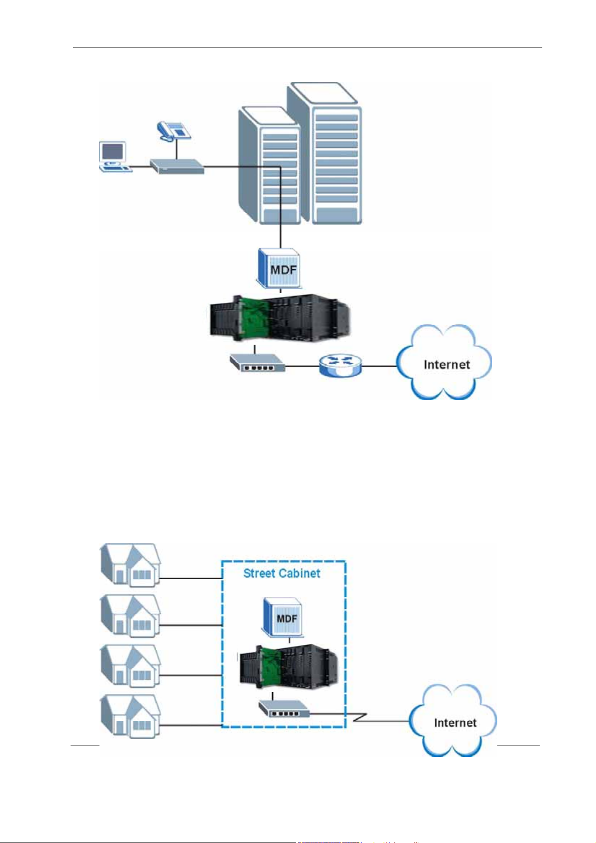
Figure 1 MTU Application
1.3.2 Curbside Application
The MSAP2000 AAM can also be used by an Internet Service Provider (ISP) in a
street cabinet to form a "mini POP (Point-of-Presence)" to provide broadband
services to residential areas that are too far away from the ISP to avail of DSL
services. Residents need an ADSL modem, connected as shown in the previous
figure.
Figure 2 Curbside Application
23
Page 24
MSAP2000 AAM User’s Guide
A
Hardware Specification
This chapter describes the front panel and rear panel of the MSAP2000 AAM and
it’s hardware specification.
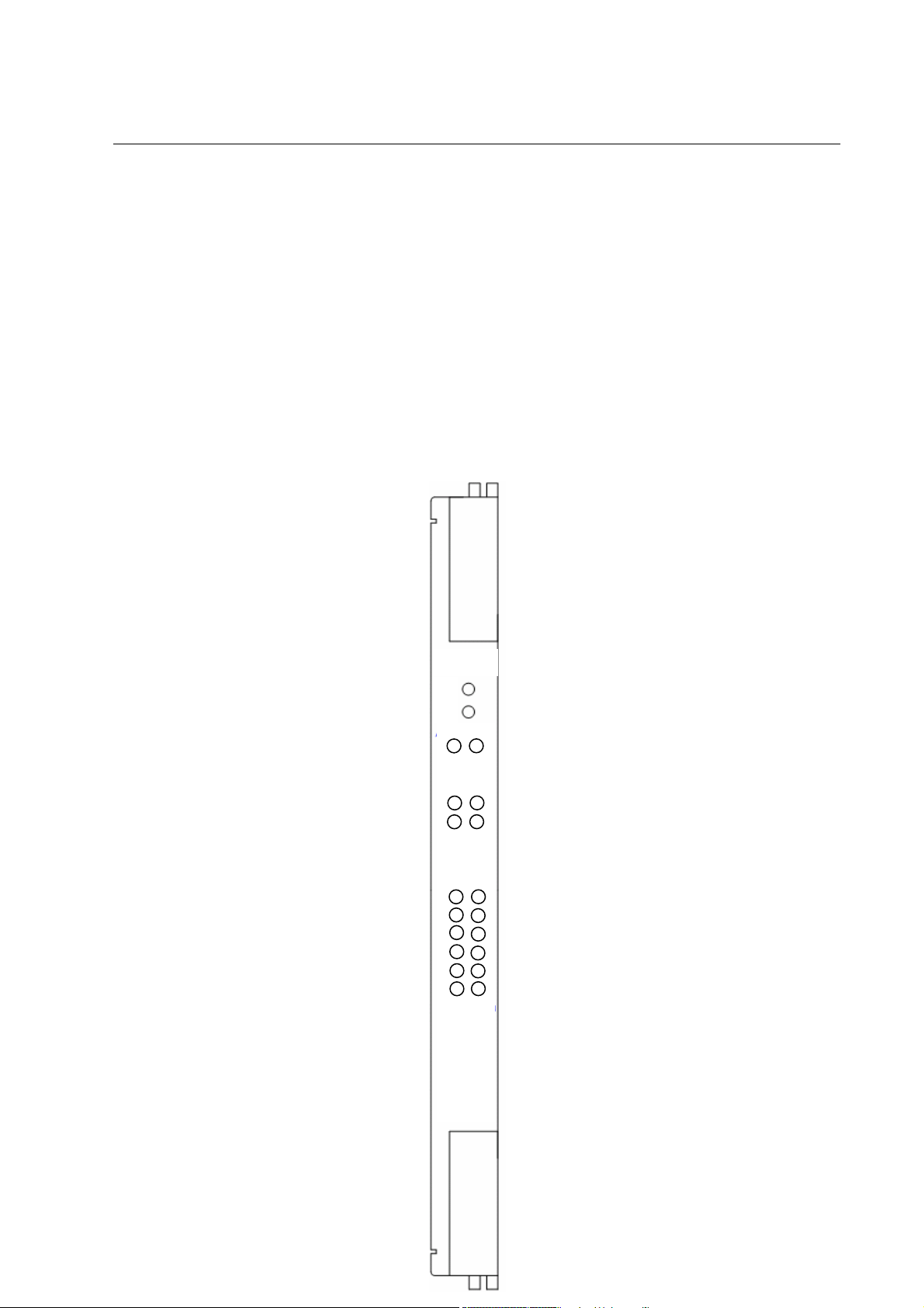
2.1 Front Panel
The figure shows the front panel of the MSAP2000 AAM.
Figure 3 Front Panel
C HAPTER 2
AM
ACTV
FAI L
SYS ALM
Up LINK
1 1
2 2
SPD LINK
ADSL2/2+
1 2
3 4
5 6
7 8
9 10
11 12
24
Page 25
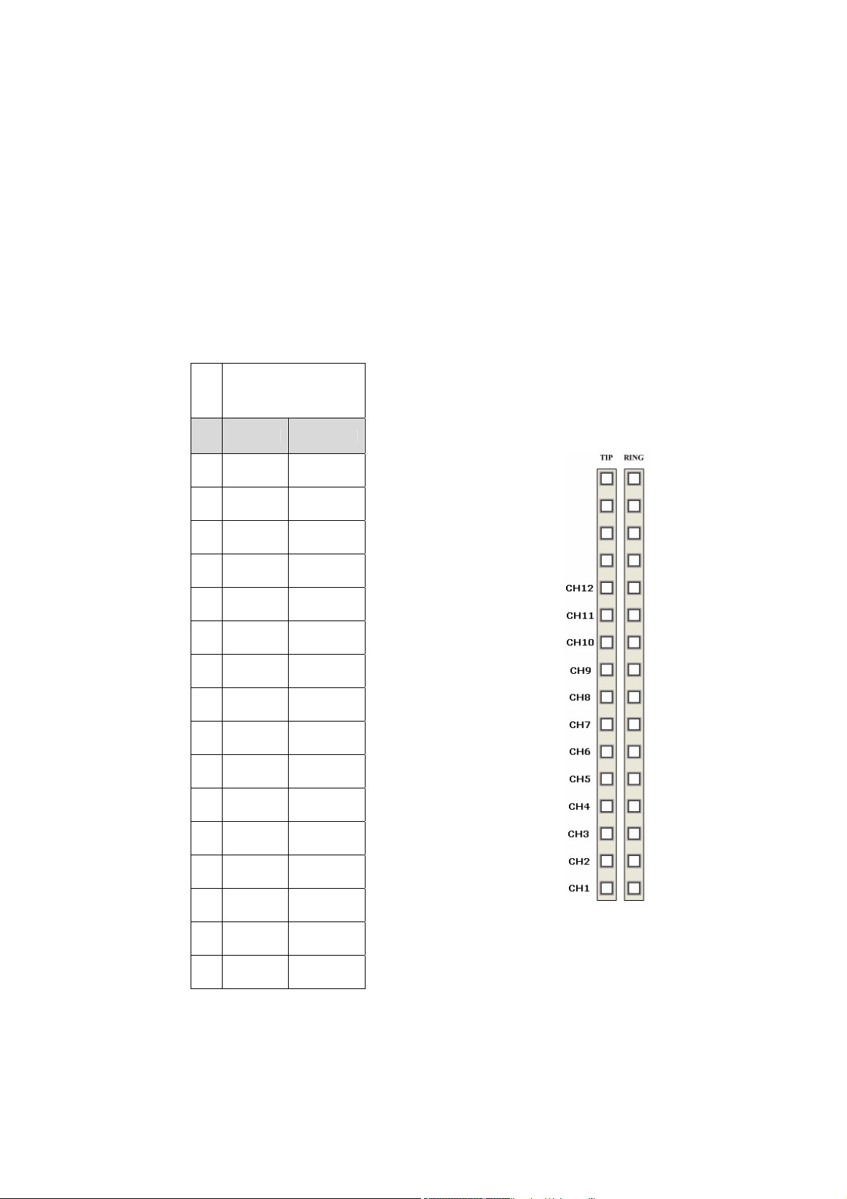
2.1.1 Rear Access Ports
The following backplane wiring illustrations describe how the the port number
matches the wiring post at the system backplane. MSAP2000 AAM module
provides up to 12 channels. Use wire wrapping on TIP and RING for connection.
The first channel (CH1) is located on the bottom, and the last channel – CH12 is
on the fifth wiring post counting from the top. Connect these ports to a computer, a
hub, an Ethernet switch or router.
MSAP2000
TIP RING
1
2
AAM
3
4
5
CH12-TIP CH12-RING
6
CH11-TIP CH11-RING
7
CH10-TIP CH10-RING
8
CH9-TIP CH9-RING
9
CH8-TIP CH8-RING
10
CH7-TIP CH7-RING
11
CH6-TIP CH6-RING
12
CH5-TIP CH5-RING
13
CH4-TIP CH4-RING
14
CH3-TIP CH3-RING
15
CH2-TIP CH2-RING
16
CH1-TIP CH1-RING
25
Page 26

2.1.2 Front Panel LEDs
The following table describes the LED indicators on the front panel of the
MSAP2000 AAM.
Table 1 LED status and description
LED Status Description
ACTV
(Green)
FAIL(Red)
ALM (Red)
LAN ACTV(Green)
LAN SPD(Green)
GREEN:Normal Working
OFF:CPU or Power Failure
ON: CPU or Auto-Detection Failure
OFF:Normal Working
ON: Alarm Occur
TWINKLE:Looptesting
OFF:No Alarm
ON/ TWINKLE:LAN PORT
Connect to Ethernet equipment
OFF:LAN PORT disconnection
ON:Transport speed is
100BaseTx。
OFF:Transport speed is 10BaseT
or Disconnection
26
Page 27

MSAP2000 AAM User’s Guide
2.1.3 Console Port (via MSAP2000 MPM)
For local management, you can use a computer with terminal emulation
software configured to the following parameters:
2.1.3.1 Default Ethernet Settings
• VT100 terminal emulation
• 115,20 0 bp s
• No parity, 8 data bits, 1 stop bit
• No flow control
Connect the male 9-pin end of the console cable to the console port of the
MSAP2000 SHELF. Connect the female end to a serial port (COM1, COM2 or
other COM port) of your computer. Use a USB-to-COM port convertor if there’s no
COM port available on your computer. Most USB-to-COM port convertor requires
a driver, please make sure the USB-to-COM port convertor can be recognized by
your computer before connecting to console port. Refer to UI operation manual for
user name, password, and more details.
The factory default negotiation settings for the Ethernet ports on the MSAP2000
AAM are:
• Speed: Auto
• Duplex: Auto
• Flow control: on
2.1.4 Notes About MDFs (Main Distribution Frames)
An MDF is usually installed between end-users' equipment and the telephone
company (CO) in a basement or telephone room. The MDF is the point of
termination for the outside telephone company lines coming into a building and
the telephone lines in the building.
27
Page 28

MSAP2000 AAM User’s Guide
2.1.5 Hardware specification
MSAP2000 AAM Specification
Hardware
Interface Standard
Line Code Ethernet
Nominal Test Impedance
Output Port
Network
Microprocessor WINBOND W90N740,
Flash ROM Flash EPROM (1MB),(4MB)
RAM SDRAM (2MB),(32MB)
Input Port Number 2 ports
Output Port Number 12 port
ADSL type ITU-T G.992.1, G.992.2,
Switch Capacity Up to 16k MAC address
VLAN Port-based VLAN
Filtering PPPoE, DHCP, NetBIOS,
In band SNMP v1/v2
Management
MIB RFC1155, RFC2578
Out of band Proprietary path through
Input Power
Power Consumption
Environment
Dimension
Weight
EMI
ESD
48VDC/0.6A
19.2W
Operation Temperature & Humidity 0°C to +60°C
Storage Temperature & Humidity 0°C to +40°C
Height 213 ± 1mm
Width 18 ± 1mm
Depth 275 ± 1mm
305 ± 2 g
CNS 13438 or CISPR 22
IEC 61000-4-2 Class 1
Wintergra WIN717D4HBC
Ω (balance)
75
G.992.3, G.992.4, G.992.4
MAC address filtering
802.1p Priority Preservation
Spanning tree protocol
Tag, untag VLAN per 802.1q
Support GVRP for uplink
MAC, Multicast, Packet, IGMP
IP, ARP filter
Web-based management
Support Telnet
Full OAM&P functions
RFC 1212
TDM backplane connection
Up to 95% ; relative humidity
Up to 50% ; relative humidity
28
Page 29

MSAP2000 AAM User’s Guide
C HAPTER 3
Web Configurator
This chapter tells how to access and navigate the web configurator.
3.1 Web Configurator Overview
The web configurator allows you to use a web browser to manage the MSAP2000
AAM.
3.2 Accessing the Web Configurator
The web configurator is an HTML-based management interface that allows easy
MSAP2000 AAM setup and management via Internet browser. Use Internet
Explorer 6.0 and later versions. The recommended screen resolution is 1024 by
768 pixels.
In order to use the web configurator you need to allow:
• Web browser pop-up windows from your device. Web pop-up blocking is
3.2.1 Password
enabled by default in Windows XP SP (Service Pack) 2.
• JavaScripts (enabled by default).
• Java permissions (enabled by default).
1 Launch your web browser and enter the IP address of the MSAP2000
AAM ("192.168.1.1" is the factory default) in the Location or Address
field. Press Enter.
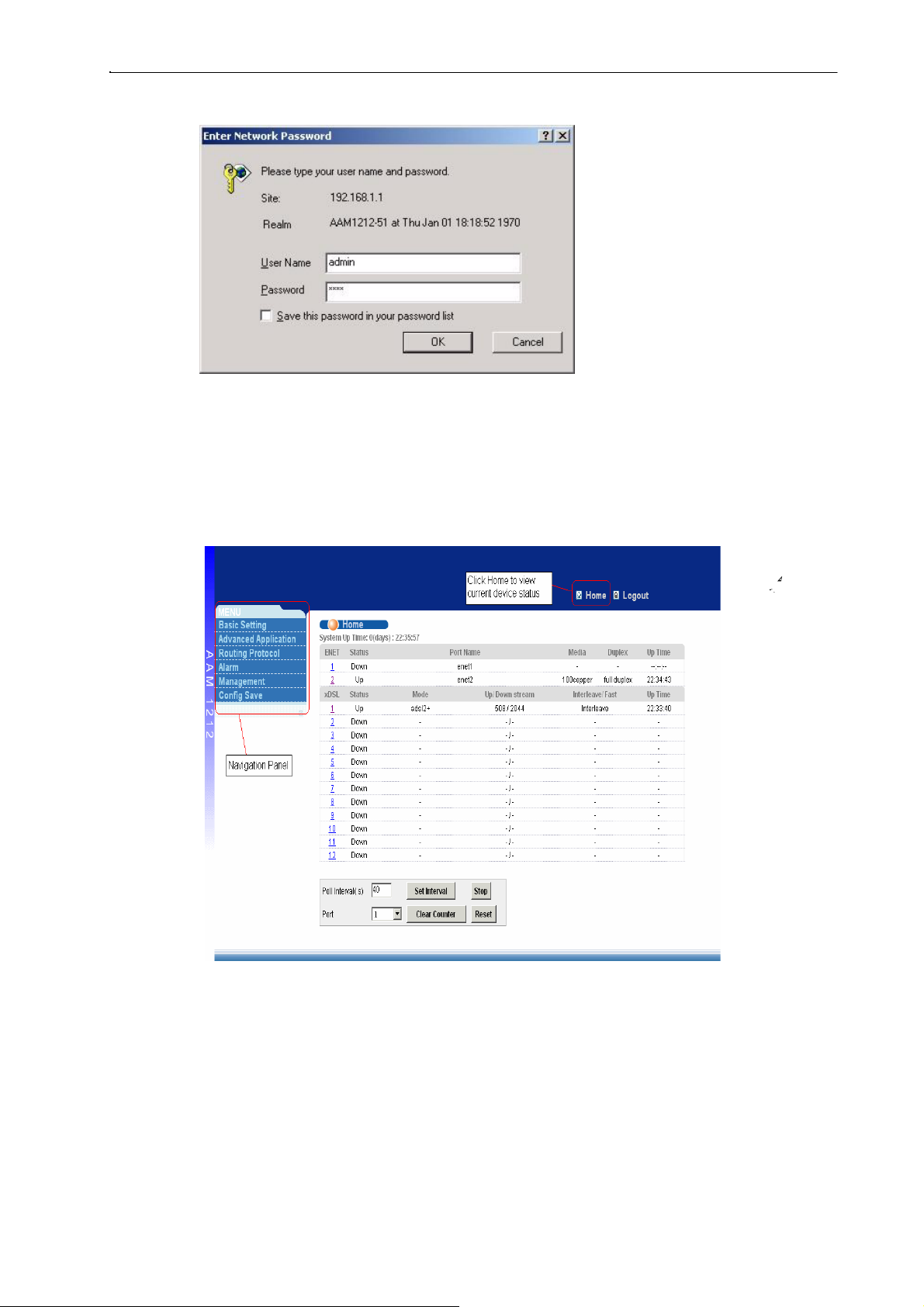
2 The Password screen appears. Type "admin" in the user name field
and your password (factory default "1234") in the password field. Click
OK.
Introduction
29
Page 30
MSAP2000 AAM User’s Guide
Figure 4 Login Screen
3.3 Home Screen
This is the web configurator's Home screen.
Figure 5 Home Screen
30
Page 31

MSAP2000 AAM User’s Guide
In the navigation panel, click a main link to reveal a list of submenu links. Click a
submenu link to go to the corresponding screen.
Table 3 Navigation Panel Sub-links Overview
Basic Setting Advanced Application Routing Protocol
Management Config Save
The following table briefly describes the functions of the screens that you open by
clicking the navigation panel's sub-links.
Table 4 Web Configurator Screens
LINK DESCRIPTION
Basic Settings
System Info Use this screen to display general system and hardware monitoring
General Setup Use this screen to configure general identification information about the
information
MSAP2000 AAM and the time and date settings
31
Page 32

MSAP2000 AAM User’s Guide
Table 4 Web Configurator Screens (continued)
LINK
Switch Setup
IP Setup
ENET Port Setup Use this screen to configure settings for the Ethernet ports
xDSL Port Setup
xDSL Profiles
Setup
xDSL Line Data
Advanced Application
VLAN
IGMP Snooping Use this screen to configure IGMP snooping and display the results.
DESCRIPTION
Use this screen to set up global switch parameters such as IGMP
snooping, MAC address learning, GARP and priority queues.
Use this screen to configure the system and management IP
addresses and subnet masks.
Use this screen to go to screens for configuring settings for individual
DSL ports.
Use this screen to go to screens for configuring profiles for the DSL
ports.
Use this screen to go to screens for viewing DSL line operating values,
bit allocation and performance counters.
Use this screen to go to screens for viewing and configuring the VLAN
settings.
Static Multicast
Filtering Use this screen to configure packet filtering.
MAC Filter
Spanning Tree
Protocol
Port
Authentication
Port Security
DHCP Relay Use this screen to configure the DHCP relay settings
Syslog Use this screen to configure the syslog settings.
Access Control
Routing Protocol
Static Routing
Management
Maintenance
Diagnostic Use this screen to view system logs and test port(s).
MAC Table
ARP Table Use this screen to view the MAC address to IP address resolution table.
Use this screen to configure static multicast filter entries.
Use this screen to configure MAC filtering for each port.
Use this screen to go to screens for displaying Rapid Spanning Tree
Protocol (RSTP) information and configuring RSTP settings.
Use this screen to go to screens for configuring RADIUS and IEEE
802.1x security settings.
Use this screen to limit the number of MAC address that can be learned
on a port.
Use this screen to configure the system login password and configure
SNMP and remote management.
Use this screen to configure static routes. A static route defines how the
MSAP2000 AAM should forward traffic by configuring the TCP/IP
parameters manually.
Use this screen to perform firmware and configuration file maintenance
as well as restart the system.
Use this screen to view the MAC addresses (and types) of devices
attached to what ports and VLAN IDs.
Config Save
Config Save
Use this screen to save the device’s configuration into the nonvolatile
memory (the MSAP2000 AAM’s storage that remains even if the
MSAP2000 AAM’s power is turned off).
32
Page 33

MSAP2000 AAM User’s Guide
3.4 Saving Your Configuration
Click Apply in a configuration screen when you are done modifying the settings in
that screen to save your changes back to the run time memory. Settings in the
run time memory are lost when the MSAP2000 AAM's power is turned off.
Click Config Save in the navigation panel and then the Save button to save your
configuration to nonvolatile memory. Nonvolatile memory refers to the MSAP2000
AAM's storage that remains even if the MSAP2000 AAM's power is turned off.
Note: Use Config Save when you are done with a configuration session.
3.5 Changing Your Password
After you log in for the first time, it is recommended you change the default
Administrator password in the Logins screen. Click Advanced Application,
Access Control and then Logins to display the next screen.
Figure 6 Web Configurator: Change Password
3.6 Logging Out of the Web Configurator
Click Logout in a screen to exit the web configurator. You have to log in with your
password again after you log out. This is recommended after you finish a
management session both for security reasons and so you don’t lock out other
MSAP2000 AAM administrators.
Figure 7 Web Configurator: Logout Screen
33
Page 34

MSAP2000 AAM User’s Guide
C HAPTER 4
Initial Configuration
This chapter describes initial configuration for the MSAP2000 AAM.
4.1 Initial Configuration Overview
This chapter shows what you first need to do to provide service to ADSL
subscribers.
4.2 Initial Configuration
This chapter uses the web configurator for initial configuration. See the commands
part of this User's Guide for information on the commands. Use Internet Explorer
6 and later versions with JavaScript enabled.
1 Make sure your computer is in the same subnet as the MSAP2000 AAM's
default IP address (192.168.1.1) and subnet mask (255.255.255.0).
2 Launch your web browser and type "192.168.1.1" in the Location or
Address field. Press Enter.
3 The Enter Network Password screen appears. Type "admin" in the user
name field and your password (factory default "1234") in the password field.
Click OK.
Figure 8 Login Screen
4 Click Basic Setting and then IP Se tup.
34
Page 35

MSAP2000 AAM User’s Guide
Figure 9 Basic Setting IP Setup Menu
5 Use this screen to change the IP address, subnet mask, and default gateway
IP address for your network. Apply the settings. If you change the MSAP2000
AAM’s IP address, you must use the new IP address if you want to access the
web configurator again.
Figure 10 IP setup
6 Skip to step 15 if you have your subscribers use VPI 0 and VCI 33 (the
default for all of the ADSL ports). Otherwise, use the following steps to
change the VPI and VCI settings for all of the ADSL ports.
First you will delete the default virtual channel from all of the ADSL ports
(you cannot edit it).
Adding another virtual channel without deleting the default virtual channel is
not recommended since you cannot set the new channel to be the port's
super channel. The super channel can forward frames belonging to multiple
VLAN groups (that are not assigned to other channels). A channel that is
not the super channel can only forward frames with a single VLAN ID (that
is configured on that channel). The MSAP2000 AAM would drop any
frames received from the subscriber that are tagged with another VLAN ID.
Then you will configure a new virtual channel for a port and copy it to the other
ADSL ports
7 Under Basic Setting, click xDSL Port Setup.
35
Page 36

MSAP2000 AAM User’s Guide
Figure 11 Basic Setting xDSL Port Setup Menu
8 Click VC Setup.
Figure 12 xDSL Port Setup
9 Click a virtual channel's Select radio button and click Delete. Click OK
in the next screen.
36
Page 37

MSAP2000 AAM User’s Guide
Figure 13 Deleting a PVC
10 Click All and then Apply.
Figure 14 Select Ports
11 Select Super Channel to allow the channel to forward frames belonging to
multiple VLAN groups (that are not assigned to other channels). Enter the
VPI and VCI that you need. Leave the other default settings and click Add.
37
Page 38

MSAP2000 AAM User’s Guide
Figure 15 Adding a New Channel
12 Click the new channel's Select radio button. Click Copy and then Paste.
Figure 16 Copying the PVC
13 Click All to select every port.
14 Click Apply to paste the settings.
Figure 17 Select Ports
15 Click Config Save and Config Save.
38
Page 39

MSAP2000 AAM User’s Guide
Figure 18 Config Save Menu
16 Click Save.
Figure 19 Config Save Screen
You can now use the device (with the other settings set to the defaults) to provide
service to ADSL subscribers. See the rest of this chapter for information on other
default settings.
4.3 Default Settings
VLAN Default Settings
One VLAN is created (this is also the management VLAN).
This table lists major default settings.
Table 5 Default Settings
VID: 1
Registration Fixed for the Ethernet and ADSL ports
Tagging: Untagged for all ports
STP Default Settings
Enable/Disable State: Disabled
Operational Mode: auto
(ADSL) Port Profile Default Settings
Name:
DEFVAL Profile Status: Active
Latency Mode: Interleave
Upstream ADSL Settings: Downstream ADSL Settings:
Max Rate 512 Kbps 2048 Kbps
Min Rate 64 Kbps 64 Kbps
Interleave Delay 4 ms 4 ms
Max SNR 31 db 31 db
39
Page 40

MSAP2000 AAM User’s Guide
V
Table 5 Default Settings
Min SNR 0 db 0 db
Target SNR 6 db 6 db
Name:
DEFVAL_MAX Profile Status: Active
Latency Mode: Interleave
Upstream ADSL Settings: Downstream ADSL Settings:
Max Rate 512 Kbps 9088 Kbps
Min Rate 64 Kbps 64 Kbps
a
4 ms
Interleave Delay
Max SNR 31 db 31 db
Min SNR 0 db 0 db
Target SNR 6 db 6 db
Virtual Channel Default Settings
4 ms
Super channel: Enabled
VPI: 0
VCI: 33
VC Profile: DEFVAL
Default
C Profile Settings
DEFVAL Profile Settings
Encapsulation: RFC 1483
Multiplexing: LLC-based
Traffic Class: UBR
PCR: 300000 Kbps
CDVT: 0
DEFVAL_VC Profile Settings
Encapsulation: RFC 1483
Multiplexing: VC-based
Traffic Class: UBR
PCR: 300000 Kbps
CDVT: 0
Default IGMP Filter Profile Settings
The DEFV AL IGMP filter profile is assigned to all of the ADSL ports by default. It allows a port to
join all multicast IP addresses (224.0.0.0~239.255.255.255).
40
Page 41

MSAP2000 AAM User’s Guide
C HAPTER 5
H
ome and Port
Statistics Screens
This chapter describes the Home (status) and Port Statistics screens.
5.1 Home and Port Statistics Screens Overview
The Home screen of the web configurator displays a port statistical summary
with links to each port for showing statistical details.
5.2 Home Screen
To view the port statistics, click Home in any web configurator screen to display the
Home
screen as shown next.
Figure 20 Home
41
Page 42

MSAP2000 AAM User’s Guide
The following table describes the labels in this screen.
Table 6 Home
LABEL DESCRIPTION
System up Time This field shows how long the system has been running since the last time it
was started.
The following fields are related to the Ethernet ports.
ENET This field displays the number of the Ethernet port. Click a port number to
display that port’s statistics screen (refer to 9.2.1).
Port Name This field displays the name of the Ethernet port.
Media This field displays the speed and the type of media that this Ethernet port is
using for a connection (100copper or 10cop per). “-” displays when the port is
disabled or not connected.
Duplex This field displays whether the port is using half or full-duplex communication. “-“
displays when the port is disabled or not connected.
Up Time This field shows the total amount of time in hours, minutes and seconds the
port’s connection has been up. “--:--:--“ displays when the port is disabled or
not connected.
The following fields are related to the ADSL ports.
xDSL This identifies the ADSL port. Click a port number to display the ADSL Port
Statistics screen (refer to Section 6.2.2 on page 67).
Status This field shows whether the port is connected (Up) or not (Down).
Mode This field shows which ADSL operational mode the port is set to use. “-
“ displays when the port is not connected.
Up/Down stream This field shows the number of kilobytes per second that a port is set to
transmit and receive.
Interleave/Fast This field shows the port’s ADSL latency mode (fast or interleave).
Up Time This field shows the total amount of time in hours, minutes and seconds the
port’s connection has been up. “-“ displays when the port is not connected.
The following fields and buttons apply to the whole screen.
Poll Interval(s) The text box displays how often (in seconds) this screen refreshes. You
may change the refresh interval by typing a new number in the text box
and then clicking Set Interval.
Stop Click Stop to halt system statistic polling.
Clear Counter Select a port from the Port drop-down list box and then click Clear
Counter to erase the recorded statistical information for that port.
5.2.1 Ethernet Port Statistics
In the Home screen, click an Ethernet port's number to display that port's
statistics screen as shown next.
42
Page 43

MSAP2000 AAM User’s Guide
Figure 21 Ethernet Port Statistics
The following table describes the labels in this screen.
Table 7 Ethernet Port Statistics
LABEL DESCRIPTION
Return Click this link to go back to the Home screen.
Port Use this drop-down list box to select a port for which you wish to view
Port Name This field displays the name that you have configured for the port.
Rx bytes This field shows the number of octets of Ethernet frames received that are from 0
Rx packets This field shows the number of packets received on this port (including
Rx error fcs This field shows the number of frames received with an integral length of 64 to
Rx multicast This field shows the number of good multicast frames received of 64 to 1518 octets
Rx broadcast This field shows the number of good broadcast frames received of 64 to 1518
statistics. This field identifies the port described in this screen.
to 1518 octets in size, counting the ones in bad packets, not counting framing bits
but counting FCS (Frame Check Sequence) octets. An octet is an 8-bit binary digit
(byte).
multicast, unicast, broadcast and bad packets).
1518 octets and containing a Frame Check Sequence error.
in length (for non VLAN) or 1522 octets (for VLAN), not including Broadcast frames.
Frames with range or length errors are also not taken into account.
octets in length (for non VLAN) or 1522 octets (for VLAN), not including multicast
frames. Frames with range or length errors are also not taken into account.
43
Page 44

MSAP2000 AAM User’s Guide
Table 7 Ethernet Port Statistics (continued)
LABEL DESCRIPTION
Rx mac pause This field shows the number of valid IEEE 802.3x Pause frames received on
Rx fragments This field shows the number of frames received that were less than 64 octets
Rx error overrun This field shows how many times an Ethernet transmitter overrun occurred.
Rx error mru This field shows the number of received frames that were dropped due
Rx dropped This field shows the number of received frames that were steamed into the
Rx jabber This field shows the number of frames received that were longer than 1518 octets
Rx error alignment This field shows the number of frames received that were 64 to 1518 (non
Rx oversize This field shows the number of frames received that were bigger than 1518 (non
Rx undersize This field shows the number of frames received that were less than 64 octets
Rx discard This field shows the number of frames dropped based on packet filtering.
Tx bytes This field shows the number of bytes that have been transmitted on this port.
Tx packets This field shows the number of packets transmitted on this port.
Tx multicast This field shows the number of good multicast frames transmitted on this port
Tx broadcast This field shows the number of broadcast frames transmitted on this port
Tx mac_pause This field shows the number of valid IEEE 802.3x Pause frames transmitted on
Tx fragments This field shows the number of transmitted frames that were less than 64
Tx frames This field shows the number of complete good frames transmitted on this port.
Tx error underrun This field shows the number of outgoing frames that were less than 64 octets long.
Tx undersize This field shows the number of frames transmitted that were less than 64 octets
Tx jabber This field shows the number of frames transmitted that were longer than 1518
Tx oversize This field shows the number of frames transmitted that were bigger than 1518
packet(<=64) This field shows the number of frames received and transmitted (including bad
packet(65-127) This field shows the number of frames received and transmitted (including bad
this port.
long, and contained an invalid FCS, including non-integral and integral lengths.
to exceeding the Maximum Receive Unit frame size.
MSAP2000 AAM, but later dropped because of a lack of system resources.
(non VLAN) or 1522 octets (VLAN) and contained an invalid FCS,
including alignment errors.
VLAN) or 1522 (VLAN) octets long but contained an invalid FCS and a non-
integral number of octets.
VLAN) or 1522 (VLAN) octets and contained a valid FCS.
long and contained a valid FCS.
This includes collisions but not jam signal or preamble/SFD (Start of Frame
Delimiter) bytes.
(not including broadcast frames).
(not including multicast frames).
this port.
octets long, and with an incorrect FCS value.
long and contained a valid FCS.
octets (non VLAN) or 1522 octets (VLAN) and contained an incorrect FCS value.
octets (non VLAN) or 1522 (VLAN) and contained a valid FCS.
frames) that were 64 octets or less in length (this includes FCS octets but
excludes framing bits).
frames) that were 65 to 127 octets in length (this includes FCS octets but
excludes framing bits).
44
Page 45

MSAP2000 AAM User’s Guide
r
p
acket(to
t
al)
s
the totalnumberofreceived
and transmitted
p
ackets
y
Stop
p
t
r
r
r
w
Table 7 Ethernet Port Statistics (continued)
LABEL DESCRIPTION
packet(128-255) This field shows the number of frames received and transmitted (including
packet(256-511) This field shows the number of frames received and transmitted (including
packet(512-1023) This field shows the number of frames received and transmitted (including
packet(1024-1518)
packet(1522) This field shows the number of frames received and transmitted (including bad
bad frames) that were 128 to 255 octets in length (this includes FCS octets
but excludes framing bits).
bad frames) that were 256 to 511 octets in length (this includes FCS octets
but excludes framing bits).
bad frames) that were 512 to 1023 octets in length (this includes FCS
octets but excludes framing bits).
This field shows the numbe
(including bad frames) that were 1024 to 1518 octets in length (this
includes FCS octets but excludes framing bits).
frames) that were 1519 to 1522 octets in length (this includes FCS octets but
excludes framing bits).
broadcast(total) This field shows the total number of received and transmitted broadcast
multicast(total) This field shows the total number of received and transmitted multicast frames.
octet(total) This field shows the total number of received and transmitted octets (unicast,
Poll Interval(s) The text box displa
Click Sto
Clear Counte
This field show
multicast and broadcast).
may change the refresh interval by typing a new number in the text box
and then clicking Set Interval.
Select a po
Counter to erase the recorded statistical information for that port.
5.2.2 ADSL Port Statistics
In the Home screen, click an ADSL port's number to display that port's
statistics screen as shown next.
of frames received and transmitted
s how often (in seconds) this screen refreshes. You
o halt system statistic polling.
t from the Port d
op-do
n list box and then click Clear
.
45
Page 46

MSAP2000 AAM User’s Guide
x
x
r
r
r
Figure 22 ADSL Port Statistics
The following table describes the labels in this screen.
Table 8 ADSL Port Statistics
LABEL DESCRIPTION
Return Click this link to go back to the Home screen.
xDSL Port Use this drop-down list box to select a port for which you wish to view
Port Name This field displays the name that you have configured for the
port. Tx packets This field shows the number of packets transmitted on this port.
Rx packets This field shows the number of packets received on this port.
Tx broadcast
packets
statistics. This field identifies the port described in this screen.
This field shows the number of packets transmitted on this port
Rx broadcast
packets
T
discard packets This field shows the numberof outgoing packets that were dropped on this port.
discard packets This field shows the numberofreceived packetsthatwere dropped on this port.
R
Erro
s This field shows the number of e
Rx rate This field shows the number of kilobytes per second received on this port.
This field shows the number of broadcast packetsreceived on this port.
or packets on this port.
46
Page 47

MSAP2000 AAM User’s Guide
Table 8 ADSL Port Statistics (continued)
LABEL DESCRIPTION
Tx bytes This field shows the number of kilobytes that have been transmitted on this port.
Rx bytes This field shows the number of kilobytes that have been received on this port.
VPI/VCI This field displays the Virtual Path Identifier (VPI) and Virtual Circuit Identifier (VCI)
Tx packets This field shows the number of packets transmitted on each
channel. Rx packetsThis field shows the number of packets received on each channel.
Tx rate This field shows the number of kilobytes per second transmitted on each
channel. Rx rate This field shows the number of kilobytes per second received on each channel.
Tx cells This field shows the number of ATM cells transmitted on each channel.
Rx cells This field shows the number of ATM cells received on each channel.
Errors This field shows the number of error packets on each channel.
Poll Interval(s) The text box displays how often (in seconds) this screen refreshes. You may
Stop Click Stop to halt system statistic polling.
Clear Counter Select a port from the Port drop-down list box and then click Clear
of channels on this port.
change the refresh interval by typing a new number in the text box and then
clicking Set Interval.
Counter to erase the recorded statistical information for that port.
47
Page 48

MSAP2000 AAM User’s Guide
Basic Setting Screens
This chapter describes how to configure the System Information, General
Setup, Switch Setup, IP Setup and ENET Port Setup screens.
6.1 Basic Setting Screens Overview
The System Information screen displays general MSAP2000 AAM
information (such as firmware version number) and hardware polling
information (such as fan status).
The General Setup screen allows you to configure general MSAP2000 AAM
identification information. It also allows you to set the system time manually or get
the current time and date from an external server when you turn on your
MSAP2000 AAM. The real time is then displayed in the MSAP2000 AAM logs.
The Switch Setup screen allows you to set up and configure global switch
features.
The IP Setup screen allows you to configure a MSAP2000 AAM IP address,
subnet mask and DNS
(domain name server) for management purposes.
The ENET Port Setup screen allows you to configure settings for the Ethernet
6.2 System Information
ports.
See Chapter 8 on page 83 for how to use the xDSL Port Setup screens to configure
the ADSL
ports.
In the navigation panel, click Basic Setting and then System Information to
display the screen as shown. You can check the firmware version number and
monitor the hardware status in this screen.
C HAPTER 6
48
Page 49

r
r
MSAP2000 AAM User’s Guide
Figure 23 System Information
The following table describes the labels in this screen.
Table 9 System Information
LABEL DESCRIPTION
System Name This field displays the MSAP2000 AAM's model name.
ZyNOS F/W This field displays the version number of the AAM’s cur
Version date created.
ent firmware including the
DSP F/W Version This field displays the Digital Signal Processorfirmware version number. This is
the modem code fi
Hardware Version This field displays the hardware version number of your AAM.
Serial Number This field displays the serial number of your AAM.
Ethernet Address This field refers to the Ethernet MAC (Media Access Control) address of the AAM.
Hardware Monitor
Enable Select this check box to turn the hardware monitor on or clear it to turn the
hardware monitor off.
Temperature Unit
Select C to display all temperature measurements in degrees Celsius. Select F
to display all temperature measurements in degrees Fahrenheit.
mware.
49
Page 50

(
t
Stop
p
MSAP2000 AAM User’s Guide
Table 9 System Information (continued)
New threshold Configure new threshold settings in the fields below and click Apply to use them.
Temperature (Hi) Use these fields to configure the highest temperature limit at each sensor
LABEL DESCRIPTION
Temperature Each temperature sensor can detect and report the temperature. Temperature
sensor 1 is near the ADSL line driver. Temperature sensor 2 is near the ADSL
chipset. Temperature sensor 3 is near the central processing unit.
Current This shows the current temperature at this sensor.
MAX This field displays the maximum temperature measured at this sensor.
MIN This field displays the minimum temperature measured at this sensor.
Average This field displays the average temperature measured at this sensor.
Threshold (Low) This field displays the lowest temperature limit at this sensor.
Threshold (Hi) This field displays the highest temperature limit at this sensor.
Status This field displays Normal for temperatures below the threshold and Over
for those above.
Voltage The power supply for each voltage has a sensor that can detect and report
the voltage.
Current This is the current voltage reading.
MAX This field displays the maximum voltage measured at this point.
MIN This field displays the minimum voltage measured at this point.
Average This field displays the average voltage measured at this sensor.
Threshold (Low) This field displays the lowest voltage limit at this sensor.
Threshold (Hi) This field displays the highest voltage limit at this sensor.
Status Normal indicates that the voltage is within an acceptable operating range at
this point; otherwise Abnormal is displayed.
Use this section of the screen to configure the hardware monitor threshold settings.
Te mp erature Use these fields to configure the lowest temperature limit at each sensor.
Low)
Volt. (Hi) Use these fields to configure the highest voltage limit at each sensor.
Volt. (Low) Use these fields
oconfigurethelowestvoltage limit at each sensor.
Poll Interval(s) The text box displays how often (in seconds) this screen refreshes. You
may change the refresh interval by typing a new number in the text box
and then clicking Set Interval.
Click Sto
to haltstatisticpolling.
6.3 General Setup
Click Basic Setting and General Setup in the navigation panel to display the
screen as shown.
50
Page 51

MSAP2000 AAM User’s Guide
Figure 24 General Setup
The following table describes the labels in this screen.
Table 10 General Setup
LABEL DESCRIPTION
Host Name Choose a descriptive name for identification purposes. This name consists of up to
Location Enter the geographic location of MSAP2000 AAM. You can use up to 31 ASCII
Contact Person's Enter the name of the person in charge of MSAP2000 AAM up to 31 ASCII Name
Model This field displays your device type.
Use Time Server Enter the time service protocol that a timeserver uses. Not all timeservers
When Bootup support all protocols, so you may have to use trial and error to find a protocol
Time Server IP Enter the IP address (or URL if you configure a domain name server in the IP
Address Setup screen) of your timeserver. The searches for the timeserver for up to
Current Time This field displays the time you open this menu (or refresh the menu).
31 ASCII characters; spaces are allowed.
characters; spaces are not allowed.
characters; spaces are not allowed.
that works. The main differences between them are the time format.
When you select the Daytime (R FC 867) format, the switch displays the day,
month, year and time with no time zone adjustment. When you use this format
it is recommended that you use a Daytime timeserver within your geographical
time zone.
Time (RFC-868) format displays a 4-byte integer giving the total number
of seconds since 1970/1/1 at 0:0:0.
NTP (RFC-1305) is similar to Time (RFC-868).
None is the default value. Enter the time manually. Each time you turn on the
MSAP2000 AAM, the time and date will be reset to 2000-1-1 0:0.
60 seconds. If you select a timeserver that is unreachable, then this screen
will appear locked for 60 seconds. Please wait.
51
Page 52

MSAP2000 AAM User’s Guide
Table 10 General Setup (continued)
LABEL DESCRIPTION
New Time Enter the new time in hour, minute and second format. The new time then
(hh:min:ss) appears in the Current Time field after you click Apply .
Current Date This field displays the date you open this menu.
New Date (yyyy- Enter the new date in year, month and day format. The new date then appears
mm-dd) in the Current Date field after you click Apply.
Time Zone Select the time difference between UTC (Universal Time Coordinated, formerly
known as GMT, Greenwich Mean Time) and your time zone from the drop-
Apply Click Apply to save your changes to the MSAP2000 AAM’s volatile memory. The
Cancel Click Cancel to start configuring the screen again.
down list box.
MSAP2000 AAM loses these changes if it is turned off or loses power, so use the
Config Save link on the navigation panel to save your changes to the non-
volatile memory when you are done configuring.
6.4 IGMP Snooping
IGMP (Internet Group Multicast Protocol) is a session-layer protocol used to
establish membership in a multicast group - it is not used to carry user data.
Refer to RFC 1112 and RFC 2236 for information on IGMP versions 1 and 2
respectively.
A switch can passively snoop on IGMP Query, Report and Leave (IGMP version 2)
packets transferred between IP multicast routers/switches and IP multicast hosts
to learn the IP multicast group membership. It checks IGMP packets passing
through it, picks out the group registration information, and configures
multicasting accordingly. IGMP snooping allows the switch to learn multicast
groups without you having to manually configure them.
The switch forwards multicast traffic destined for multicast groups (that it has
learned from IGMP snooping or that you have manually configured) to ports that
are members of that group. The switch discards multicast traffic destined for
multicast groups that it does not know. IGMP snooping generates no additional
network traffic, allowing you to significantly reduce multicast traffic passing
through your switch.
52
Page 53

MSAP2000 AAM User’s Guide
6.5 Switch Setup Screen
Click Basic Setting and then Switch Setup in the navigation panel to display
the screen as shown.
Figure 25 Switch Setup
The following table describes the labels in this screen.
Table 11 Switch Setup
LABEL DESCRIPTION
IGMP Snooping Select Active to enable IGMP snooping have group multicast traffic only
MAC Address MAC address learning reduces outgoing traffic broadcasts. For MAC address
Learning learning to occur on a port, the port must be active.
Aging Time Enter a time from 10 to 765 seconds. This is how long all dynamically learned
GARP Timer:
Switches join VLANs by making a declaration. A declaration is made by issuing a Join message
using GARP. Declarations are withdrawn by issuing a Leave message. A Leave All message
terminates all registrations. GARP timers set declaration timeout values. See the chapter on VLAN
setup for more background information.
Join Timer Join Timer sets the duration of the Join Period timer for GVRP in milliseconds.
Leave Timer Leave Timer sets the duration of the Leave Period timer for GVRP in
forwarded to ports that are members of the VLAN, significantly reducing
multicast traffic passing through your MSAP2000 AAM.
MAC addresses remain in the MAC address table before they age out (and
must be relearned).
Each port has a Join Period timer. The allowed Join Time range is between
100 and 65535 milliseconds; the default is 200 milliseconds. See the chapter
on VLAN setup for more background information.
milliseconds. Each port has a single Leave Period timer. Leave Time must be
two times larger than Join Timer; the default is 600 milliseconds.
53
Page 54

MSAP2000 AAM User’s Guide
Table 11 Switch Setup (continued)
LABEL DESCRIPTION
Leave All Timer Leave All Timer sets the duration of the Leave All Period timer for GVRP in
Port Isolation Turn on port isolation to block communications between subscriber ports.
Switch Mode Select Standalone to use both of the MSAP2000 AAM’s Ethernet ports (LAN 1
Priority Queue Assignment
IEEE 802.1p defines up to 8 separate traffic types by inserting a tag into a MAC-layer frame
that contains bits to define class of service. Frames without an explicit priority tag are given the
default priority of the ingress port. Use the next two fields to configure the priority level-tophysical queue mapping.
The switch has 4 physical queues that you can map to the 8 priority levels. On the switch, traffic
assigned to higher index queues gets through faster while traffic in lower index queues is dropped if
the network is congested.
See also Queuing Method and Priority in Port Setup for related information.
Priority Level (The following descriptions are based on the traffic types defined in the IEEE
802.1d standard (which incorporates IEEE 802.1p).
Level 7 Typically used for network control traffic such as router configuration
messages. Level 6 Typically used for voice traffic that is especially sensitive to jitter (jitter is the
Level 5 Typically used for video that consumes high bandwidth and is sensitive to jitter.
Level 4 Typically used for controlled load, latency-sensitive traffic such as SNA (Systems
Level 3 Typically used for “excellent effort” or better than best effort and would include
Level 2 This is for “spare bandwidth”.
Level 1 This is typically used for non-critical “background” traffic such as bulk transfers
Level 0 Typically used for best-effort traffic.
Apply Click Apply to save your changes to the MSAP2000 AAM’s volatile memory.
Cancel Click Cancel to begin configuring this screen afresh.
milliseconds. Each port has a single Leave All Period timer. Leave All Timer
must be larger than Leave Timer.
When you enable port isolation you do not need to configure the VLAN to
isolate subscribers.
and LAN 2 ) as uplink ports.
Note: Standalone mode is recommended for network
topologies that use loops.
Use Daisychain mode to cascade (daisychain) multiple MSAP2000 AAMs.
The MSAP2000 AAM uses Ethernet port one (LAN 1) as an uplink port to
connect to the Ethernet backbone and uses Ethernet port two (LAN 2) to
connect to another (daisychained or subtending) MSAP2000 AAM.
Note: Daisychain mode is recommended for network
topologies that do not use loops.
variations in delay).
Network Architecture) transactions.
important business traffic that can tolerate some delay.
that are allowed but that should not affect other applications and users.
The MSAP2000 AAM loses these changes if it is turned off or loses power, so
use the Config Save link on the navigation panel to save your changes to the
non-volatile memory when you are done configuring.
54
Page 55

MSAP2000 AAM User’s Guide
6.6 IP Setup
Click Basic Setting and then IP Setup in the navigation panel to display the
screen as shown. Use this screen to configure the system and management IP
addresses and subnet masks.
Figure 26 IP Setup
The following table describes the labels in this screen.
Table 12 IP Setup
LABEL DESCRIPTION
IP Enter the IP address of your MSAP2000 AAM in dotted decimal notation
IP Mask
Apply IP setting Click Apply IP setting to save your changes to the device’s IP address
Cancel Click Cancel to begin configuring the fields again
Default Gateway Enter the IP address of the default outgoing gateway in dotted decimal
Apply Gateway
Cancel Click Cancel to begin configuring the fields again.
6.7 ENET Port Setup
Click Basic Setting and then ENET Port Setup in the navigation panel to enter
the Ethernet port configuration screen.
for example 1.2.3.4.
Enter the IP subnet mask of your MSAP2000 AAM in dotted decimal
notation for example
255.255.255.0.
and/or subnet mask to the MSAP2000 AAM’s volatile memory. The
MSAP2000 AAM loses these changes if it is turned off or loses power, so
use the Config Save link on the navigation panel to save your changes
to the non-volatile memory when you are done configuring.
notation.
Click Apply Gateway setting to save your changes to the device’s IP
address setting and/or subnet mask to the MSAP2000 AAM’s volatile
memory. The MSAP2000 AAM loses these changes
if it is turned off or loses power, so use the Config Save link on the
navigation panel to save your changes to the non-volatile memory when
you are done configuring
55
Page 56

MSAP2000 AAM User’s Guide
Figure 27 ENET Port Setup
The following table describes the fields in this screen.
Table 13 ENET Port Setup
LABEL DESCRIPTION
Port This is the port index number.
Active Select this check box to enable a port. The factory default for all ports is enabled. A
Name Enter a descriptive name that identifies this port. You can use up to 31 ASCII
Speed Mode Select the type of Ethernet connection for this port. When you don’t use auto-
Duplex The MSAP2000 AAM uses full duplex Ethernet connections.
Apply Click Apply to save your changes to the MSAP2000 AAM’s volatile memory.
Cancel Click Cancel to begin configuring the fields again.
port must be enabled for data transmission to occur.
characters; spaces are not allowed.
negotiation, you must make sure that the settings of the peer Ethernet port are
the same in order to connect.
Select Auto (auto-negotiation) to have the MSAP2000 AAM automatically
determine the type of connection that the Ethernet port has. When the peer
Ethernet device has auto- negotiation turned on, the MSAP2000 AAM negotiates
with the peer to determine the connection speed. If the peer Ethernet port does
not have auto-negotiation turned on, the MSAP2000 AAM determines the
connection speed by detecting the signal on the cable and using full duplex.
Select 10 Copper if the Ethernet port has a 10 MB electrical connection. Select
100 Copper if the Ethernet port has a 100 MB electrical connection.
The MSAP2000 AAM loses these changes if it is turned off or loses power, so
use the Config Save link on the navigation panel to save your changes to the
non-volatile memory when you are done configuring.
56
Page 57

MSAP2000 AAM User’s Guide
ADSL Port Setup
This chapter explains how to configure settings for profiles and individual ADSL
ports. It also covers how to configure virtual channels and virtual channel profiles.
7.1 ADSL Standards Overview
These are the ADSL standards and rates that the MSAP2000 AAM supports at the
7.2 Downstream and Upstream
7.3 Profiles
time of writing.
Table 14 Maximum Transfer Rates of the ADSL Ports
STANDARD MAXIMUM DOWNSTREAM MAXIMUM UPSTREAM
G.dmt 8160 Kbps 1024 Kbps
ANSI T1.413 issue 2 8160 Kbps 1024 Kbps
G.lite 1536 Kbps 512 Kbps
ADSL2 12000 Kbps 1200 Kbps
ADSL2+ 24000 Kbps 1200 Kbps
Downstream refers to traffic going out from the MSAP2000 AAM to the
subscriber's ADSL modem or router. Upstream refers to traffic coming into the
MSAP2000 AAM from the subscriber's ADSL modem or router.
A profile is a table that contains a list of pre-configured ADSL settings. Each
ADSL port has one (and only one) profile assigned to it at any given time. The
profile defines the latency mode and upstream/downstream latency delay,
maximum and minimum upstream/ downstream rates, the target
upstream/downstream signal noise margins, and the maximum and minimum
upstream/downstream acceptable noise margins of all the ADSL ports that have
this profile. You can configure multiple profiles, including profiles for
troubleshooting.
Profiles allow you to configure ADSL ports efficiently. You can configure all of the
ADSL ports with the same profile, thus removing the need to configure the ADSL
ports one-by-one. You can also change an individual ADSL port by assigning it a
different profile.
57
C HAPTER 7
Page 58

MSAP2000 AAM User’s Guide
For example, you could set up different profiles for different kinds of accounts (for
example, economy, standard and premium). Assign the appropriate profile to an
ADSL port and it takes care of a large part of the port's configuration maximum
and minimum transfer rates. You still get to individually enable or disable each
port, as well as configure its channels and operational mode. See later in this
chapter for how to configure profiles.
7.4 Interleave Delay
Interleave delay is the wait (in milliseconds) that determines the size of a single
block of data to be interleaved (assembled) and then transmitted. Interleave delay
is used when transmission error correction (Reed- Solomon) is necessary due to a
less than ideal telephone line. The bigger the delay, the bigger the data block size,
allowing better error correction to be performed.
Reed-Solomon codes are block-based error correcting codes with a wide range of
applications. The Reed-Solomon encoder takes a block of digital data and adds
extra "redundant" bits. The Reed-Solomon decoder processes each block and
attempts to correct errors and recover the original data.
7.4.1 Fast Mode
Fast mode means no interleaving takes place and transmission is faster (a "fast
channel"). This would be suitable if you have a good line where little error
correction is necessary.
7.5 Configured Versus Actual Rate
You configure the maximum rate of an individual ADSL port by modifying its
profile or assigning a different profile to the port. However, due to noise and other
factors on the line, the actual rate may not reach the maximum that you specify.
Even though you can specify arbitrary numbers for a profile, the actual rate is
always a multiple of 32 Kbps. If you enter a rate that is not a multiple of 32 Kbps,
the actual rate will be the next lower multiple of 32Kbps. For instance, if you
specify 60 Kbps for a port, the actual rate for that port will not exceed 32 Kbps,
and if you specify 66 Kbps, the actual rate will not be over 64Kbps.
Regardless of a profile's configured upstream and downstream rates, the
MSAP2000 AAM automatically limits the actual rates for each individual port to
the maximum speeds supported by the port's ADSL operational mode. For
example, if you configure a profile with a maximum downstream rate of 25000
Kbps, and apply it to a port set to use G.dmt, the MSAP2000 AAM automatically
uses a maximum downstream rate of 8160 Kbps. This means that if you
configure a profile with very high rates, you can still use it with any port. See Table
14 on page 83 for a list of the maximum rates supported by the different ADSL
standards.
58
Page 59

MSAP2000 AAM User’s Guide
7.6 Default Settings
The default profile always exists and all of the ADSL ports use the default profile
settings when the MSAP2000 AAM is shipped. The default profile's name is set
to DEFVAL. The default profile's maximum downstream rate can only be obtained
when using the G.dmt standard. Configure a profile with a maximum downstream
rate of 1536 Kbps or less for use with G.lite.
Refer to the chapter on initial configuration for the settings of the default profile and
ADSL port default settings.
7.7 xDSL Port Setup
Click Basic Setting and then xDSL Port Setup in the navigation panel to open
the following screen.
Figure 28 xDSL Port Setup
59
Page 60

MSAP2000 AAM User’s Guide
The following table describes the fields in this screen.
Table 15 xDSL Port Setup
LABEL DESCRIPTION
VC Setup Click VC Setup to open the VC Setup screen where you can configure VC
Copy Port Do the following to copy settings from one DSL port to another DSL port or ports.
settings for the DSL ports.
1. Select the number of the DSL port from which you want to copy settings.
2. Select the settings that you want to copy.
3. Click Paste and the following screen appears.
4. Select to which ports you want to copy the settings. Use All to select
every port. Use None to clear all of the check boxes.
5. Click Apply to paste the settings.
Active Select this check box to copy this port’s active setting. This is configured in the
xDSL Port Setting screen.
Customer Info Select this check box to copy this port’s subscriber information. This is
configured in the xDSL Port Setting screen.
Customer Tel Select this check box to copy this port’s subscriber’s telephone number.
This is configured in the xDSL Port Setting screen.
2+ Features Select this check box to copy this port’s ADSL2+ feature settings. These
are configured in the xDSL Port Setting screen.
Profile&Mode Select this check box to copy this port’s port profile settings and ADSL operational
mode. The port profile settings are configured in the xDSL Profiles Setup screen.
The ADSL operational mode is configured in the xDSL Port Setting screen.
IGMP Filter Select this check box to copy this port’s IGMP filter settings. These are
configured in the IGMP Filter Profile screen.
Security Select this check box to copy this port’s security settings. This is configured in the
Port Security screen (see the chapter on port security).
Frame Type Select this check box to copy this port’s allowed frame type. This is
configured in the Static VLAN Setting screen (see the chapter on VLAN).
Virtual Channels Select this check box to copy this port’s virtual channel settings. These
are configured in the VC Setup screen.
Alarm Profile Select this check box to copy this port’s alarm profile. This is configured in the
Alarm Profile Setup screen.
PVID & Priority Select this check box to copy this port’s PVID and priority settings. These are
configured in the VLAN Port Setting screen (see the chapter on VLAN).
60
Page 61

MSAP2000 AAM User’s Guide
Table 15 xDSL Port Setup (continued)
LABEL DESCRIPTION
Packet Filter Select this check box to copy this port’s packet filter settings. These are
configured in the Packet Filtering screen (see the chapter on packet filtering).
Port This field shows the port index number.
Active This field shows whether the port is enabled or not.
Customer Info This field shows information you configured in the xDSL Port Setting
screen to identify the subscriber.
Customer Tel This field shows the subscriber’s telephone number you configured in the
xDSL Port Setting screen.
Profile This field shows which profile is assigned to this port.
Mode This field shows which ADSL operational mode the port is set to use. Channels
This field displays the number of PVCs (Permanent Virtual Circuits) that are
configured for this port.
7.7.1 xDSL Port Setting
Click Basic Setting, xDSL Port Setup in the navigation panel and then a port's
index number to open the following screen.
Figure 29 xDSL Port Setting
61
Page 62

MSAP2000 AAM User’s Guide
The following table describes the fields in this screen.
Table 16 xDSL Port Setting
LABEL DESCRIPTION
Last Page Click this to return to the previous screen.
Active Select this check box to turn on this ADSL port.
Customer Info Enter information to identify the subscriber connected to this ADSL port. You
can use up to 31 printable ASCII characters (including spaces and hyphens).
Customer Tel Enter information to identify the telephone number of the subscriber
connected to this ADSL port. You can use up to 15 ASCII characters
(including spaces and hyphens).
Profile Select a profile of ADSL settings (such as the transfer rate, interleave delay
and signal to noise ratio settings) to assign to this port. Use the Port Profile
screen to configure port profiles.
Mode Select the port’s ADSL operational mode. Select the mode that the subscriber’s
device uses or auto to have MSAP2000 AAM automatically determine the mode
to use. See Table 14 on page 83 for information on the individual ADSL modes.
Alarm Profile The alarm profile defines thresholds that trigger an alarm when exceeded. IGMP
Filter Profile The IGMP filter profile defines which multicast groups a port can join. Select a
profile of IGMP filter settings to assign to this port. Use the IGMP Filter Profile
screen to configure IGMP filter profiles (see Table 51 on page 103).
ADSL2/2+ feature These are features available with ADSL2/2+. The subscriber’s ADSL device
must also support the individual features in order to use them. At the time of
writing these features have not been fully tested and their performance and
interoperability cannot be guaranteed.
Annex L Enable the Annex L feature to use reach extended ADSL2. This allows increased
ADSL2 connection distances.
PMM Enable the Power ManageMent (PMM) feature to reduce the amount of
power used overall and reduces the instances of the connection going
down. PMM increases or decreases the transmission power based on line
conditions. PMM also decreases the number of service interruptions.
SRA Enable Seamless Rate Adaptation (SRA) to automatically adjust the connection’s
data rate according to line conditions without interrupting service.
Apply Click Apply to save your changes to the MSAP2000 AAM’s volatile memory.
The MSAP2000 AAM loses these changes if it is turned off or loses power, so
use the Config Save link on the navigation panel to save your changes to the
non-volatile memory when you are done configuring.
Cancel Click Cancel to begin configuring the fields again.
7.8 Virtual Channels
Defining virtual channels (also called Permanent Virtual Circuits or PVCs) allows
you to set priorities for different services or subscribers. You can define up to eight
channels on each DSL port and use them for different services or levels of service.
You set the PVID that is assigned to untagged frames received on each channel.
You also set an IEEE 802.1p priority for each of the PVIDs. In this way you can
assign different priorities to different channels (and consequently the services that
get carried on them or the subscribers that use them).
62
Page 63

MSAP2000 AAM User’s Guide
For example, you want to give high priority to voice service on one of the ADSL
ports.
First configure a static VLAN on the MSAP2000 AAM for voice on the port.
Then do the following:
• Configure a channel on the port for voice service.
• Set the channel to use the PVID of the static VLAN you configured.
• Assign the channel a high priority.
7.8.1 Super Channel
The MSAP2000 AAM forwards frames belonging to VLAN groups that are not
assigned to specific channels to the super channel. Enable the super channel
option to allow a channel forward frames belonging to multiple VLAN groups
(that are not assigned to other channels). The super channel functions in the
same way as the channel in a single channel environment. One port can have
only one super channel.
7.8.2 LLC
LLC is a type of encapsulation where one VC (Virtual Circuit) carries multiple
protocols with each packet header containing protocol identifying information.
Despite the extra bandwidth and processing overhead, this method may be
advantageous if it is not practical to have a separate VC for each carried protocol,
for example, if charging heavily depends on the number of simultaneous VCs.
7.8.3 VC Mux
VC Mux is a type of encapsulation where, by prior mutual agreement, each
protocol is assigned to a specific virtual circuit, for example, VC1 carries IP, VC2
carries IPX, and so on. VC-based multiplexing may be dominant in environments
where dynamic creation of large numbers of ATM VCs is fast and economical.
7.8.4 Virtual Channel Profile
Virtual channel profiles allow you to configure the virtual channels efficiently. You
can configure all of the virtual channels with the same profile, thus removing the
need to configure the virtual channels one-by-one. You can also change an
individual virtual channel by assigning it a different profile.
The MSAP2000 AAM provides two default virtual channel profiles: DEFVAL (for
LLC encapsulation) and DEFVAL_VC (for VC encapsulation). By default, all
virtual channels are associated to DEFVAL.
63
Page 64

MSAP2000 AAM User’s Guide
7.9 VC Setup Screen
Click Basic Setting and then xDSL Port Setup in the navigation panel and then the
VC Setup link to open the following screen.
Use this screen to view and configure a port's channel (PVC) settings.
Figure 30 VC Setup
The following table describes the fields in this screen.
Table 17 VC Setup
LABEL DESCRIPTION
xDSL Port Setup Click xDSL Port Setup to go to the screen where you can configure DSL
port settings.
Port Use this drop-down list box to select a port for which you wish to view or
configure settings.
Super Channel The MSAP2000 AAM forwards frames belonging to VLAN groups that are
not assigned to specific channels to the super channel.
Enable the super channel option to have this channel forward frames
belonging to multiple VLAN groups (that are not assigned to other channels).
The super channel functions in the same way as the channel in a single
channel environment.
VPI Type the Virtual Path Identifier for a channel on this port.
VCI Type the Virtual Circuit Identifier for a channel on this port.
64
Page 65

MSAP2000 AAM User’s Guide
Table 17 VC Setup
LABEL DESCRIPTION
VC Profile Use the drop-down list box to select a VC profile to assign to this channel.
PVID Type a PVID (Port VLAN ID) to assign to untagged frames received on this
Priority Type the priority value (0 to 7) to add to incoming frames without a (IEEE 802.1p)
Add, Apply Click Add to add channel settings on a port.
Cancel Click Cancel to start configuring the screen again.
Show Port Select the number of an ADSL port for which to display VC settings (or display
Index This field displays the number of the PVC. Click a PVC’s index number to use
Port This field displays the number of the ADSL port on which the PVC is
configured. VPI/VC This field displays the Virtual Path Identifier (VPI) and Virtual Circuit Identifier
VC Profile This shows which VC profile the channel is set to use.
PVID This is the PVID (Port VLAN ID) assigned to untagged frames or priority frames (0
Priority This is the priority value (0 to 7) added to incoming frames without a (IEEE 802.1p)
channel. You cannot configure a PVID for a super channel.
This must be the VLAN ID of a VLAN that is already configured. The port that
you are configuring must also be set to the fixed status in the VLAN.
priority tag. An asterisk (*) denotes a super channel.
Click Apply to save channel setting changes for a port.
Click Add or Apply to save your changes to the volatile memory.
The MSAP2000 AAM loses these changes if it is turned off or loses power, so
use the Config Save link on the navigation panel to save your changes to the
non-volatile memory when you are done configuring.
all of them).
the top of the screen to edit the PVC.
Note: At the time of writing, you can only edit the VC profile. If you
want to change other settings, add a new PVC with the
desired settings. Then you can delete any unwanted PVCs.
(VCI). The VPI and VCI identify a channel on this port.
Click a link in the VPI/VCI column to open a screen where you can edit the VPI/VCI
settings.
VID) received on this channel. An asterisk (*) denotes a super channel.
priority tag. An asterisk (*) denotes a super channel.
65
Page 66

MSAP2000 AAM User’s Guide
Table 17 VC Setup
LABEL DESCRIPTION
Delete Do the following to remove one or more PVCs.
1. Select a PVC’s Select radio button.
2. Click Delete.
3. Click OK if you want to remove the PVC from other ports. Click Cancel to
only remove the one you selected.
4. If you clicked OK, the following screen appears.
5. Select to which ports you want to copy the settings. Use All to select
every port. Use None to clear all of the check boxes.
6. Click Apply to delete the channels.
66
Page 67

MSAP2000 AAM User’s Guide
Table 17 VC Setup
LABEL DESCRIPTION
Copy, Paste Do the following to copy settings from one PVC to another port or ports.
1. Click the Select radio button of the PVC from which you want to copy
settings.
2. Click Paste.
3. The following screen appears.
4. Select to which ports you want to copy the settings. Use All to select
every port. Use None to clear all of the check boxes.
5. Click Apply to copy the settings.
7.10 Port Profile Screen
A profile is a list of settings that you define. Then you can assign them to
one or more individual ports.
Click Basic Setting and then xDSL Profiles Setup in the navigation panel
to open the following screen.
67
Page 68

MSAP2000 AAM User’s Guide
Figure 31 Port Profile
The following table describes the fields in this screen.
Table 18 Port Profile
LABEL DESCRIPTION
VC Profile Click VC Profile to open the VC Profile screen where you can configure
Alarm Profile Click Alarm Profile to open the Alarm Profile screen where you can
IGMP Filter Profile Click IGMP Filter Profile to open the IG MP Filter Profile screen where you
Index This is the port profile index number.
Name These are the names of individual profiles. The DEFVAL profile always exists and
Latency Mode This is the ADSL latency mode (Fast or Interleave) for the ports that belong to
Down/Up Stream These are the maximum downstream and upstream transfer rates for the ports
Rate (kbps) that belong to this profile.
Modify Select a profile’s Select radio button and click Modify to edit the profile.
Delete Select a profile’s Select radio button and click Delete to remove the profile.
The rest of the screen is for profile configuration.
virtual channel profiles.
configure limits that trigger an alarm when exceeded.
can configure IGMP multicast filter profiles.
all of the DSL ports have it assigned to them by default. You can use up to 31
ASCII characters; spaces are not allowed.
this profile.
Name When editing a profile, this is the name of this profile. When adding a profile,
type a name (up to 31 characters) for the profile.
68
Page 69

A
r
r
y
MSAP2000 AAM User’s Guide
Table 18 Port Profile (continued)
LABEL DESCRIPTION
Latency Mode This field sets the ADSL latency mode for the ports that belong to this
Up Stream The following parameters relate to upstream transmissions.
Max Rate Type a maximum upstream transfer rate (32 to 3000 Kbps) for this profile.
(kbps.) Configure the maximum upstream transfer rate to be less than the maximum
Min Rate Type the minimum upstream transfer rate (32 to 3000 Kbps) for this port.
(kbps.) Configure the minimum upstream transfer rate to be less than the maximum
Interleave Configure this field when you set the Latency Mode field to Interleave. Type
Delay (ms) the number of milliseconds (1-255) of interleave delay to use for upstream
Max SNR (db) Type the maximum upstream signal to noise margin (0-31 dB).
Min SNR (db) Type the minimum upstream signal to noise margin (0-31 dB). Configure the
Target SNR Type the target upstream signal to noise margin (0-31 dB). Configure the target
(db.) upstream signal to noise margin to be greater than or equal to the minimum
upstream signal to noise margin and less than or equal to the maximum
Down Stream The following parameters relate to downstream transmissions.
Max Rate Type a maximum downstream transfer rate (32 to 25000 Kbps) bps for this port.
(kbps.) Configure the maximum downstream transfer rate to be greater than the maximum
Min Rate Type the minimum downstream transfer rate (32 to 25000 Kbps) for this port.
(Kbps.) Configure the minimum downstream transfer rate to be less than the maximum
Interleave Configure this field when you set the Latency Mode field to interleave. Type the
Delay (ms) number of milliseconds (1-255) of interleave delay to use for upstream transfers. It
Max SNR (db) Type the maximum downstream signal to noise margin (0-31 dB).
Min SNR (db) Type the minimum downstream signal to noise margin (0-31 dB). Configure
Target SNR Type the target downstream signal to noise margin (0-31 dB). Configure the target
(db) downstream signal to noise margin to be greater than or equal to the minimum
Add
Cancel Click Cancel to start configuring the screen again.
profile. Select Fast mode to use no interleaving and have faster
transmission (a “fast channel”). This would be suitable if you have a good
line where little error correction is necessary.
Select Interleave mode to use interleave delay when transmission error correction
(Reed- Solomon) is necessary due to a less than ideal telephone
line. See Section 8.4 on page 84 for more on interleave delay.
downstream transfer rate.
upstream transfer rate.
transfers. It is recommended that you configure the same latency delay for both
upstream and downstream.
minimum upstream signal to noise margin to be less than or equal to the
maximum upstream signal to noise margin.
upstream signal to noise margin.
upstream transfer rate.
downstream transfer rate.
is recommended that you configure the same latency delay for both upstream and
downstream.
the minimum downstream signal to noise margin to be less than or equal to
the maximum downstream signal to noise margin.
downstream signal to noise margin and less than or equal to the maximum
downstream signal to noise margin.
Click
dd to save you
changesto the AAM’s volatile memo
. The AAM loses
these changes if it is turned off or loses power, so use the Config Save link on
the navigation panel to save your changes to the non-volatile memory when
you are done configuring.
69
Page 70

MSAP2000 AAM User’s Guide
7.11 ATM QoS
ATM Quality of Service (QoS) mechanisms provide the best service on a per-flow
guarantee. ATM network infrastructure was designed to provide QoS. It uses fixed
cell sizes and built-in traffic management (see the following section on traffic
shaping). This allows you to fine-tune the levels of services on the priority of the
traffic flow.
7.12 Traffic Shaping
Traffic shaping is an agreement between the carrier and the subscriber to regulate
the average rate and fluctuations of data transmission over an ATM network. This
agreement helps eliminate congestion, which is important for transmission of real
7.12.1 ATM Traffic Classes
7.12.1.1 Constant Bit Rate (CBR)
7.12.1.2 Variable Bit Rate (VBR)
time data such as audio and video connections.
These are the basic ATM traffic classes defined by the ATM Forum Traffic
Management 4.0
Specification.
Constant Bit Rate (CBR) is an ATM traffic class that provides fixed bandwidth. CBR
traffic is generally time-sensitive (doesn't tolerate delay). CBR is used for
connections that continuously require a specific amount of bandwidth. Examples
of connections that need CBR would be high-resolution video and voice.
The Variable Bit Rate (VBR) ATM traffic class is used with bursty connections.
Connections that use the Variable Bit Rate (VBR) traffic class can be grouped
into real time (rt-VBR) or non-real time (nrt-VBR) connections.
The rt-VBR (real-time Variable Bit Rate) type is used with bursty connections
that require closely controlled delay and delay variation. An example of an rtVBR connection would be video conferencing. Video conferencing requires realtime data transfers and the bandwidth requirement varies in proportion to the
video image's changing dynamics.
The nrt-VBR (non real-time Variable Bit Rate) type is used with bursty
connections that do not require closely controlled delay and delay variation. An
example of an nrt-VBR connection would be non-time sensitive data file
transfers.
70
Page 71

MSAP2000 AAM User’s Guide
7.12.1.3 Unspecified Bit Rate (UBR)
The Unspecified Bit Rate (UBR) ATM traffic class is similar to the ABR traffic class
for bursty data transfers. However, while ABR gives subscribers a set amount of
bandwidth, UBR doesn't guarantee any bandwidth and only delivers traffic when
the network has spare bandwidth.
7.12.2 Traffic Parameters
These are the parameters that control the flow of ATM traffic.
7.12.2.1 Peak Cell Rate (PCR)
Peak Cell Rate (PCR) is the maximum rate at which the sender can send cells.
This parameter may be lower (but not higher) than the maximum line speed. 1
ATM cell is 53 bytes (424 bits), so a maximum speed of 832Kbps gives a
maximum PCR of 1962 cells/sec. This rate is not guaranteed because it is
dependent on the line speed.
7.12.2.2 Sustained Cell Rate (SCR)
Sustained Cell Rate (SCR) is the mean cell rate of each bursty traffic source. It
specifies the maximum average rate at which cells can be sent over the virtual
connection. SCR may not be greater than the PCR.
7.12.2.3 Maximum Burst Size (MBS)
Maximum Burst Size (MBS) is the maximum number of cells that can be sent at
the PCR. After MBS is reached, cell rates fall below SCR until cell rate averages
to the SCR again. At this time, more cells (up to the MBS) can be sent at the
PCR again.
The following figure illustrates the relationship between PCR, SCR and MBS.
Figure 32 PCR, SCR and MBS in Traffic Shaping
71
Page 72

MSAP2000 AAM User’s Guide
7.12.2.4 Cell Delay Variation Tolerance (CDVT)
Cell Delay Variation Tolerance (CDVT) is the accepted tolerance of the difference
between a cell's transfer delay and the expected transfer delay. CDVT controls
the time scale over which the PCR is enforced. CDVT is used to determine if a
cell arrived too early in relation to PCR.
7.12.2.5 Burst Tolerance (BT)
Burst Tolerance (BT) is the maximum number of cells that the port is guaranteed
to handle without any discards. BT controls the time scale over which the SCR is
enforced. BT is used to determine if a cell arrived too early in relation to SCR. Use
this formula to calculate BT: (MBS
- 1) x (1 / SCR - 1 / PCR) = BT.
7.12.2.6 Theoretical Arrival Time (T AT)
The Theoretical Arrival Time (TAT) is when the next cell (in an ATM connection's
stream of cells) is expected to arrive. TAT is calculated based on the PCR or
SCR.
The following figure illustrates the relationship between TAT, CDVT and BT. If a
cell arrives at time A, then according to PCR or SCR, the next cell is expected to
arrive at time B. If the next cell arrives earlier than time C, it is discarded or
tagged for not complying with the TAT. Time C is calculated based on the CDVT
or BT.
Figure 32 TAT, CDVT and BT in Traffic Shaping
7.13 VC Profile Screen
Click Basic Setting and then xDSL Profiles Setup in the navigation panel
and then VC Profile to open the following screen.
72
Page 73

MSAP2000 AAM User’s Guide
Figure 33 VC Profile
The following table describes the fields in this screen.
Table 19 VC Profile
LABEL DESCRIPTION
Port Profile Click Port Profile to configure port profiles and assign them to individual ports.
Alarm Profile Click Alarm Profile to open the Alarm Profile screen where you can configure
IGMP Filter Profile Click IGMP Filter Profile to open the IGMP Filter Profile screen where you
Index This is the number of the VC profile.
Name This name identifies the VC profile.
Encap This field displays the profile’s type of encapsulation (llc or vc).
AAL The MSAP2000 AAM ADSL ports' PVCs use ATM Adaptation Layer (AAL) 5.
Class This field displays the type of ATM traffic class: cbr (constant bit rate), vbr (real-
PCR This is the Peak Cell Rate (PCR), the maximum rate at which the sender can send
CDVT This field displays the accepted tolerance of the difference between a
SCR The Sustained Cell Rate (SCR) sets the average cell rate (long-term) that can
BT Burst Tolerance (BT) is the maximum number of cells that the port is guaranteed to
Modify Select a VC profile’s Select radio button and click Modify to edit the VC profile.
Delete Select a VC profile’s Select radio button and click Delete to remove the VC profile.
The rest of the screen is for PVC configuration.
limits that trigger an alarm when exceeded.
can configure IGMP multicast filter profiles.
time variable bit rate), nrt-vbr (non-real time variable bit rate) or ubr (unspecified
bit rate).
cells.
cell’s transfer delay and the expected transfer delay.
be transmitted. SCR applies with the vbr traffic class.
Minimum Cell Rate (MCR) is the minimum rate at which the sender can send cells.
handle without any discards. BT applies with the vbr traffic class.
73
Page 74

MSAP2000 AAM User’s Guide
Table 19 VC Profile (continued)
LABEL DESCRIPTION
Name When editing a profile, this is the name of this profile. When adding a profile,
type a name for the profile. You can use up to 31 ASCII characters; spaces are
not allowed.
Encap Select the encapsulation type (LLC or VC) for this port.
Class Select CBR (constant bit rate) to specify fixed (always-on) bandwidth for voice
or data traffic.
Select UBR (unspecified bit rate) for applications that are non-time sensitive,
such as e-mail.
Select VBR (real time variable bit rate) or NRT-VBR (non real time variable
bit rate) for bursty traffic and bandwidth sharing with other applications.
PCR Divide the DSL line rate (bps) by 424 (the size of an ATM cell) to find the Peak
Cell Rate (PCR). This is the maximum rate at which the sender can send cells.
PCR applies with all of the ATM traffic classes. Type the PCR here.
CDVT Cell Delay Variation Tolerance (CDVT) is the accepted tolerance of the
difference between a cell’s transfer delay and the expected transfer delay.
CDVT applies with all of the ATM traffic classes. Type the CDVT here.
SCR The Sustained Cell Rate (SCR) sets the average cell rate (long-term) that can
be transmitted. Type the SCR, which must be less than the PCR. SCR applies
with the VBR traffic classes.
BT Burst Tolerance (BT) sets a maximum number of cells that the port is
guaranteed to handle without any discards. Type the BT here. BT applies with
the VBR traffic classes.
Add Click Add to save your changes to the MSAP2000 AAM’s volatile memory. The
MSAP2000 AAM loses these changes if it is turned off or loses power, so use
the Config Save link on the navigation panel to save your changes to the non-
volatile memory when you are done configuring.
Cancel Click Cancel to start configuring the screen again.
7.14 Alarm Profile Screen
Click Basic Setting and then xDSL Profiles Setup in the navigation panel and
then Alarm
Profile to open the following screen.
Alarm profiles define ADSL port alarm thresholds. The MSAP2000 AAM
sends an alarm trap and generates a syslog entry when the thresholds of
the alarm profile are exceeded.
Use the top part of the screen (with the Add and Cancel buttons) to add or edit
alarm profiles. The rest of the screen displays the configured alarm profiles.
74
Page 75

MSAP2000 AAM User’s Guide
Figure 34 Alarm Profile
The following table describes the fields in this screen.
Table 20 Alarm Profile
LABEL DESCRIPTION
Port Profile Click Port Profile to open the Port Profile screen. Use the Port Profile
VC Profile Click VC Profile to open the VC Profile screen where you can configure
IGMP Filter Profile Click IGMP Filter Profile to open the IGMP Filter Profile screen where you
Name Type a name to identify the alarm profile (you cannot change the name of the
Add Click Add to save your changes to the volatile memory to avoid losing
Cancel Click Cancel to start configuring the screen again.
Threshold Specify limits for the individual performance counters. The MSAP2000 AAM
ATU-C These fields are for traffic coming from the subscriber’s device.
ATU-R These fields are for traffic going from the MSAP2000 AAM.
screen to configure profiles of ADSL port settings (such as the transfer rate,
interleave delay and signal to noise ratio settings).
virtual channel profiles.
can configure IGMP multicast filter profiles.
DEFVAL profile). You can use up to 31 ASCII characters; spaces are not allowed.
these changes if it is turned off or loses power, so use the Config Save link on
the navigation panel to save your changes to the non-volatile memory when
you are done configuring.
sends an alarm tram and generates a syslog entry when one of these
thresholds is exceeded. A value of 0 disables the alarm threshold.
15 Min LOF(sec) This field sets the limit for the number of Loss Of Frame seconds that are
permitted to occur within 15 minutes.
75
Page 76

MSAP2000 AAM User’s Guide
Table 20 Alarm Profile (continued)
LABEL DESCRIPTION
15 Min LOS This field sets the limit for the number of Loss Of Signal seconds that are
(sec) permitted to occur within 15 minutes.
15 Min LPR This field sets the limit for the number of times a Loss of PoweR (on the ATUR)
15 Min ES This field sets the limit for the number of Errored Seconds that are permitted
(sec) to occur within 15 minutes.
15 Min SES This field sets the limit for the number of Severely Errored Seconds that
(sec) are permitted to occur within 15 minutes.
15 Min UAS This field sets the limit for the number of UnAvailable Seconds that are permitted
(sec) to occur within 15 minutes.
15 Min Failed This field sets the limit for the number of failed fast retrains that are permitted
Fast Retrain within 15 minutes.
Init Failure Trap Select Active to trigger an alarm for an initialization failure trap.
Fast Rate Up Specify a rate in kilobits per second (kbps). If a fast mode connection’s
upstream (bps) transmission rate increases by more than this number, then a trap is sent.
Fast Rate Down Specify a rate in kilobits per second (kbps). If a fast mode connection’s downstream
(bps) transmission rate decreases by more than this number, then a trap is sent.
Interleave Rate Up Specify a rate in kilobits per second (kbps). If an interleave mode connection’s
(bps) upstream transmission rate increases by more than this number, then a trap is
sent.
Interleave Rate Specify a rate in kilobits per second (kbps). If an interleave mode connection’s
Down (bps) upstream transmission rate decreases by more than this number, then a trap is
sent.
Alarm profiles with
xDSL port
mapping
Index This is the index number of the alarm profile.
Name This is the name of the alarm profile.
Modify Click Modify to edit a profile.
Delete Click Delete to remove a profile.
is permitted to occur within 15 minutes.
After you addanalarmprofile,you can click a portnumber’s “-“ symbol to map
the xDSL port to that alarm profile. The port’s “V” symbol in the alarm profile
were it was previously mapped changes to “-“.
7.15 IGMP Filter Profile Screen
You can use the IGMP filter profiles to control access to a service that uses a
specific multicast group (like a SIP server for example). Configure an IGMP filter
profile that allows access to that multicast group. Then assign the IGMP filter
profile to ADSL ports that are allowed to use the service.
Click Basic Setting and then xDSL Profiles Setup in the navigation panel and
then IGMP Filter Profile to open the following screen.
76
Page 77

MSAP2000 AAM User’s Guide
The DEFVAL IGMP filter profile is assigned to all of the ADSL ports by default. It
allows a port to join all multicast IP addresses (224.0.0.0~239.255.255.255). If
you want to allow an ADSL subscriber access to only specific IGMP multicast
groups, use the IGMP Filter Profile screen to configure a different profile and
then assign it to the subscriber's ADSL port in the XDSL Port Setting screen
(see Figure 44 on page 87).
The top of the screen displays the configured IGMP filter profiles. Use the bottom
part of the screen (with the Add and Cancel buttons) to add or edit alarm profiles.
Figure 35 IGMP Filter Profile
The following table describes the fields in this screen.
Table 21 IGMP Filter Profile
LABEL DESCRIPTION
Port Profile Click Port Profile to configure port profiles and assign them to individual ports.
VC Profile Click VC Profile to open the VC Profile screen where you can configure virtual
Alarm Profile Click Alarm Profile to open the Alarm Profile screen where you can
channel profiles.
configure limits that trigger an alarm when exceeded.
77
Page 78

MSAP2000 AAM User’s Guide
Table 21 IGMP Filter Profile (continued)
LABEL DESCRIPTION
Index This is the number of the IGMP filter profile. Click a profile’s index number to
edit the profile. You cannot edit the DEFVAL profile.
Name This name identifies the IGMP filter profile.
Delete Select the Delete check box and click Delete to remove an IGMP filter profile.
You cannot delete the DEFVAL profile.
Name Type a name to identify the IGMP filter profile (you cannot change the name of the
DEFVAL profile). You can use up to 31 ASCII characters; spaces are not allowed.
Start IP Enter the starting multicast IP address for a range of multicast IP addresses to
which you want this IGMP filter profile to allow access.
End IP Enter the ending multicast IP address for a range of IP addresses to which you
want this IGMP filter profile to allow access.If you want to add a single multicast
IP address, enter it in both the Start IP and End IP fields.
Add Click Add to save your changes to the MSAP2000 AAM’s volatile memory. The
MSAP2000 AAM loses these changes if it is turned off or loses power, so use
the Config Save link on the navigation panel to save your changes to the non-
volatile memory when you are done configuring.
Cancel Click Cancel to start configuring the screen again.
7.16 Line Rate Information
Click Basic Setting and then Line Data in the navigation panel to open the
following screen. This screen displays an ADSL port's line operating values.
Information obtained prior to training to steady state transition will not be valid or
will be old information.
Figure 36 Line Rate Information
78
Page 79

w
r
t
ghp
r
MSAP2000 AAM User’s Guide
The following table describes the fields in this screen.
Table 22 Line Rate Information
LABEL DESCRIPTION
Line Performance Click Line Performance to display an ADSL port’s line performance
counters. Line Data Click Line Data to display an ADSL port’s line bit allocation.
Port Use this drop-down list box to select a port for which you wish to view information.
Refresh Click Refresh to display updated information.
Port Name This field displays the name of the ADSL port.
The rate fields display the transmission rates. “Line Down” indicates that the ADSL port is
not connected to a subscriber.
Down/up Stream
Rate
Do
n/up Stream
Noise Margin
Down/up Stream
Attenuation
Down/up Stream
Attainable Rate
Service Mode This field displays the ADSL s
Trellis Encoding This field displays whether Trellis encoding is turned on or off. Trellis
Down Stream
Interleave Delay
Up Stream
Interleave Delay
Down Stream
Output Power
Info The Info Atu
a. At the time of writing, the MSAP2000 AAM always uses Trellis coding.
These are the rates (in Kbps) atwhich the porthas been sending and
receiving data.
These a
Measured in decibels (dB).
e the DSL line’s downstream and upstream noise margins.
These are the reductions in amplitude of the downstream and upstream DSL
signals. Measured in decibels (dB).
These are the highest theoretically possible transfer rates (in Kbps) at which
the port could send and receive data.
andardthat the port is using: G.dmt, G.lite
or ANSI T1.413 issue 2, ADSL2, ADSL2+, ETSI
encoding helps to reduce the noise in ADSL transmissions. Trellis may
reduce throu
ut but itmakesthe connection more stable.
a
This field displays the numberof milliseconds of interleave delay for
downstream transmissions.
This field displays the number of milliseconds of interleave delay for
upstream transmissions.
This field displays the amount of power that this port is using to transmit to the
subscriber’s ADSL modem or router. The total output power of the transceiver
varies with the length and line quality. The farther away the subscriber’s ADSL
modem or router is or the more interference there is on the line, the more power
is needed.
fields show data acquired from the ATUR (ADSL Termination
Unit – Remote), in this case the subscriber’s ADSL modem or router, during
negotiation/ provisioning message interchanges. This information can help in
identifying the subscriber’s ADSL modem or router.
The Info Atuc fields show data acquired from the ATUC (ADSL Termination
Unit – Central), in this case AAM, during negotiation/provisioning message
interchanges. The vendor ID, vendor version number and product serial number
are obtained from vendor ID fields (see ITU-T G.994.1) or R-MSGS1 (see
79
Page 80

MSAP2000 AAM User’s Guide
7.17 Line Performance
Click Basic Setting and then Line Data in the navigation panel and then the
Line Performance link to open the following screen. This screen displays an
ADSL port's line performance counters.
These counters display line performance data that has been accumulated since
the system started. The definitions of near end/far end are relative to the
MSAP2000 AAM. Downstream refers to the data that the MSAP2000 AAM sends
to the subscriber's device. Upstream refers to data that the MSAP2000 AAM
receives from the subscriber's device.
Figure 37 Line Performance
The following table describes the fields in this screen.
Table 23 Line Performance
LABEL DESCRIPTION
Line Rate Click Line Rate to display an ADSL port’s line operating
values. Line Data Click Line Data to display an ADSL port’s line bit allocation.
Port Use this drop-down list box to select a port for which you wish to view
information. Refresh Click Refresh to display updated information.
Port Name This field displays the name of the ADSL port.
Line Type “Fast” stands for non-interleaved (fast mode) and “Interleaved: stands
for interleaved mode.
Init This displays how many times the MSAP2000 AAM has initialized the DSL link.
80
Page 81

r
r
r
t
y
r
t
A
MSAP2000 AAM User’s Guide
Table 23 Line Performance (continued)
BEL DESCRIPTION
L
Down/Up Stream
BLKS
Down/Up Stream
ES
Down/Up Stream
SES
Down/Up Stream
UAS
Fast FEBE In fast mode, the number of Far End Block Errors.
Fast NEBE In fast mode, the number of Near End Block Errors.
Fast FEFEC In fast mode, the number of Far End Forward Error Count.
Fast NEFEC In fast mode, the number of Near End Forward Error Count.
Interleaved FEBE In interleaved mode, the number of Far End Block Errors.
Interleaved NEBE In interleaved mode, the number of Near End Block Errors.
In
erleaved
FEFEC
Interleaved
NEFEC
LPR This is the number of times that the subscriber’s ADSL device has experienced
15 min, 1day histor
ATUC These s
ATUR These statistics are for the connection (or traffic) going from the AAM to the
lofs The number of Loss Of Frame Seconds that have occurred within the period.
loss The number of Loss Of Signal Seconds that have occurred within the period.
lols The number of Loss Of Link seconds that have occurred within the period.
lprs The number of loss of PoweR Seconds that have occurred within the period.
eSs The number of Errored SecondS that have occurred within the period.
inits The number of initialization failure traps that have occurred within the period.
sesl The number of Severely Errored Seconds that have occurred within the period.
uasl The number of UnAvailable Seconds that have occurred within the period.
7.17.1 Line Data
Click Basic Setting and Line Data in the navigation panel and then the Line
Data link to open the following screen. This screen displays an ADSL port's line
bit allocation.
The numbe
ADSL port. A block is a set of consecutive bits associated with the path; each bit
belongs to one and only one block. Consecutive bits may not be contiguous in
time.
The Number of Errored Seconds transmitted (downstream) or received (upstream)
on this ADSL port.
The Number of Severely Errored Seconds transmitted (downstream) or received
(upstream) on this ADSL port. Severely errored seconds contained 30% or more
errored blocks or at least one defect. This is a subset of the Down/Up Stream ES.
The downstream or upstream number of UnAvailable Seconds.
of Blocks transmitted (downstream) o
eceived (upstream) on this
In interleaved mode, the numberof FarEnd Forward Error Count.
In interleaved mode, the number of Near End Forward Error Count.
a Loss of PoweR (been off).
This section of the screen displays line perfo
previous 15-minute periods, as well as for the current and previous 24 hours.
device to the AAM.
subscriber’s device.
atistics arefor the connection (ortraffic) coming from the subscriber’s
mance statistics for the currentand
81
Page 82

MSAP2000 AAM User’s Guide
Discrete Multi-Tone (DMT) modulation divides up a line's bandwidth into tones.
This screen displays the number of bits transmitted for each tone. This can be
used to determine the quality of the connection, whether a given sub-carrier loop
has sufficient margins to support ADSL transmission rates, and possibly to
determine whether certain specific types of interference or line attenuation exist.
Refer to the ITU-T G.992.1 recommendation for more information on DMT.
The better (or shorter) the line, the higher the number of bits transmitted for a
DMT tone. The maximum number of bits that can be transmitted per DMT tone is
15.
The bit allocation contents are only valid when the link is up.
In the screen shown, the downstream channel is carried on tones 48 to 255 and
the upstream channel is carried on tones 16 to 31 (space is left between the
channels to avoid interference).
Figure 38 Line Data
82
Page 83

MSAP2000 AAM User’s Guide
The following table describes the fields in this screen.
Table 24 Line Data
LABEL DESCRIPTION
Line Rate Click Line Rate to display an ADSL port’s line operating values.
Line Performance Click Line Performance to display an ADSL port’s line performance counters.
Port Use this drop-down list box to select a port for which you wish to view
information. Refresh Click Refresh to display updated information.
Port Name This field displays the name of the ADSL port.
Bit Allocation “DS carrier load” displays the number (in hexadecimal format) of bits
transmitted per DMT tone for the downstream channel (from the MSAP2000
AAM to the subscriber’s DSL modem or router).
“US carrier load” displays the number (in hexadecimal format) of bits received
per DMT tone for the upstream channel (from the subscriber’s DSL modem or
router to the MSAP2000 AAM).
83
Page 84

MSAP2000 AAM User’s Guide
C HAPTER 8
This chapter shows you how to configure 802.1Q tagged VLANs.
8.1 Introduction to VLANs
A VLAN (Virtual Local Area Network) allows a physical network to be
partitioned into multiple logical networks. Devices on a logical network belong
to one group. A device can belong to more than one group. With VLAN, a
device cannot directly talk to or hear from devices that are not in the same
group(s); the traffic must first go through a router.
In MTU (Multi-Tenant Unit) applications, VLAN is vital in providing isolation and
security among the subscribers. When properly configured, VLAN prevents one
subscriber from accessing the network resources of another on the same LAN,
thus a user will not see the printers and hard disks of another user in the same
building. If you have enabled port isolation in the Switch Setup screen, you do
not need to configure the VLAN to isolate subscribers.
VLAN also increases network performance by limiting broadcasts to a smaller
and more manageable logical broadcast domain. In traditional switched
environments, all broadcast packets go to each and every individual port. With
VLAN, all broadcasts are confined to a specific broadcast domain.
Note that a VLAN is unidirectional; it only governs outgoing traffic.
8.2 Introduction to IEEE 802.1Q Tagged VLAN
Tagged VLAN uses an explicit tag (VLAN ID) in the MAC header to identify the
VLAN membership of a frame across bridges - they are not confined to the switch
on which they were created. The VLANs can be created statically by hand or
dynamically through GVRP. The VLAN ID associates a frame with a specific VLAN
and provides the information that switches need to process the frame across the
network. A tagged frame is four bytes longer than an untagged frame and
contains two bytes of TPID (Tag Protocol Identifier, residing within the type/length
field of the Ethernet frame) and two bytes of TCI (Tag Control Information, starts
after the source address field of the Ethernet frame).
The CFI (Canonical Format Indicator) is a single-bit flag, always set to zero for
Ethernet switches. If a frame received at an Ethernet port has a CFI set to 1, then
that frame should not be forwarded as it is to an untagged port. The remaining
twelve bits define the VLAN ID, giving a possible maximum number of 4,096 (212)
VLANs. Note that user priority and VLAN ID are independent of each other. A
frame with VID (VLAN Identifier) of null (0) is called a
VLAN
84
Page 85

MSAP2000 AAM User’s Guide
priority frame, meaning that only the priority level is significant and the default
VID of the ingress port is given as the VID of the frame. Of the 4096 possible VIDs,
a VID of 0 is used to identify priority frames and value 4095 (FFF) is reserved, so
the maximum possible VLAN configurations are 4,094.
TPID
2 Bytes
User Priority
3 Bits
CFI
1 Bits
The MSAP2000 AAM handles up to 4094 VLANs (VIDs 1-4094). The switch
accepts incoming frames with VIDs 1-4094.
8.2.1 Forwarding Tagged and Untagged Frames
Each port on the switch is capable of passing tagged or untagged frames. To
forward a frame from an 802.1Q VLAN-aware switch to an 802.1Q VLANunaware switch, the switch first decides where to forward the frame and then
strips off the VLAN tag. To forward a frame from an 802.1Q VLAN-unaware
switch to an 802.1Q VLAN-aware switch, the switch first decides where to
forward the frame, and then inserts a VLAN tag reflecting the ingress port's
default VID. The default PVID is VLAN 1 for all ports, but this can be changed.
The egress (outgoing) port(s) of a frame is determined on the combination of the
destination MAC address and the VID of the frame. For a unicast frame, the
egress port based by the destination address must be a member of the VID, also;
otherwise, the frame is blocked. For a broadcast frame, it is duplicated only on
ports (except the ingress port itself) that are members of the VID, thus confining
the broadcast to a specific domain.
Whether to tag an outgoing frame depends on the setting of the egress port on
an individual VLAN and port basis (remember that a port can belong to multiple
VLANs). If the tagging on the egress port is enabled for the VID of a frame, then
the frame is transmitted as a tagged frame; otherwise, it is transmitted as an
untagged frame.
8.3 Automatic VLAN Registration
GARP and GVRP are the protocols used to automatically register VLAN
8.3.1 GARP
membership across switches.
GARP (Generic Attribute Registration Protocol) allows network switches to
register and de- register attribute values with other GARP participants within a
bridged LAN. GARP is a protocol that provides a generic mechanism for
protocols that serve a more specific application, for example, GVRP.
VLAN ID
12 bits
85
Page 86

MSAP2000 AAM User’s Guide
8.3.1.1 GARP Timers
Switches join VLANs by making a declaration. A declaration is made by issuing a
Join message using GARP. Declarations are withdrawn by issuing a Leave
message. A Leave All message terminates all registrations. GARP timers set
declaration timeout values.
8.3.2 GVRP
GVRP (GARP VLAN Registration Protocol) is a registration protocol that defines a
way for switches to register necessary VLAN members on ports across the network.
Enable this function to permit VLANs groups beyond the local switch.
Registration Fixed Fixed registration ports are permanent VLAN members.
Acceptable frame You may choose to accept both tagged and untagged
Please refer to the following table for common IEEE 802.1Q VLAN terminology.
Table 25 IEEE 802.1Q VLAN Terminology
VLAN PARAMETER
VLAN Type Permanent VLAN This is a static VLAN created manually.
This is a VLAN configured by a GVRP
VLAN Administrative
Control
VLAN Tag Control Tagged Ports belonging to the specified VLAN tag all
VLAN Port Port VID This is the VLAN ID assigned to untagged frames
TERM DESCRIPTION
Dynamic VLAN
Registration Ports with registration forbidden are forbidden to join the
Forbidden specified VLAN.
Normal Registration Ports dynamically join a VLAN using GVRP.
Untagged Ports belonging to the specified don't tag all
type incoming frames or just tagged incoming frames on a
Ingress filtering If set, the switch discards incoming frames for
port.
registration/deregistration process.
outgoing frames transmitted.
outgoing frames transmitted.
that this port received.
VLANs that do not have this port as a member
8.4 VLAN Status
Click Advanced Application and then VLAN to display the VLAN Status screen
as shown next.
86
Page 87

L
MSAP2000 AAM User’s Guide
Figure 39 VLAN Status
The following table describes the labels in this screen.
Table 26 VLAN Status
LABEL DESCRIPTION
Static VLAN Click Static VLAN Setting to configure ports to dynamically join a VLAN group or
Setting permanently assign ports to a VLAN group or prohibit ports from joining a VLAN
VLAN Port Click VLAN Port Setting to specify Port VLAN IDs (PVIDs).
Setting
The Number Of This is the number of VLANs configured on the MSAP2000 AAM.
VLAN
Page X of X This identifies which page of VLAN status information is displayed and how
The first table displays the names of the fields. The subsequent tables show the settings of the VLANs.
group.
many total pages of VLAN status information there are.
Index This is the VLAN index number.
Status This field shows how this VLAN was added to the MSAP2000 AAM; dynamically
Name / VID The name identifies an individual VLAN. The vid is the PVID, the Port VLAN ID
1~12, enet1, These columns display the VLAN’s settings for each port. A tagged port is marked
enet2 as T, an untagged port is marked as U and ports not participating in a VLAN are
Elapsed Time This field shows how long it has been since a normal VLAN was registered or a static
Poll Interval(s) The text box displays how often (in seconds) this screen refreshes. You may
Stop Click Stop to halt polling statistics.
Change Pages Click Previous Page or Next Page to show the preceding/following screen if
using GVRP or statically, that is, added as a permanent entry.
assigned to untagged frames or priority-tagged frames received on this port.
marked as “-“.
VLAN was set up.
change the refresh interval by typing a new number in the text box and then
clicking Set Interval.
the information cannot be displayed in one screen.
87
Page 88

MSAP2000 AAM User’s Guide
8.5 Static VLAN Setting
Click Advanced and then VLAN in the navigation panel and then the Static VLAN
Setting
link to display the screen as shown next.
You can assign a port to be a member of a VLAN group or prohibit a port from
joining a
VLAN group in this screen. This is an IEEE 802.1Q VLAN.
Figure 40 Static VLAN Setting
The following table describes the labels in this screen.
Table 27 Static VLAN Setting
LABEL DESCRIPTION
VLAN Status Click VLAN Status to see which ports are members of which VLANs.
VLAN Port Click VLAN Port Setting to specify Port VLAN IDs (PVIDs).
Setting
VID This field displays the ID number of the VLAN group. Click the number to edit the
VLAN settings.
Active This field indicates whether the VLAN settings are enabled (Yes) or disabled (No).
Name This field displays the descriptive name for this VLAN group.
88
Page 89

MSAP2000 AAM User’s Guide
Table 27 Static VLAN Setting (continued)
LABEL DESCRIPTION
Delete Select the check boxes of the rules that you want to remove in the Delete column
and then click the Delete button.
You cannot delete a VLAN if any PVIDs are set to use the VLAN or the VLAN is
the CPU (management) VLAN. The DEFAULT VLAN cannot be deleted when a
port’s PVID refers to it. The CPU VLAN also cannot be deleted.
Cancel Click Cancel to clear the Delete check
boxes. Active Select this check box to enable the VLAN.
You cannot disable a VLAN if any PVIDs are set to use the VLAN or the VLAN is the
CPU (management) VLAN.
Name Enter a descriptive name for this VLAN group for identification purposes.
VLAN ID Enter the VLAN ID for this static VLAN entry; the valid range is between 1 and
4094. Port The port numbers identify the MSAP2000 AAM’s ports.
Control Select Normal for the port to dynamically join this VLAN group using GVRP.
This is available for the Ethernet ports.
Select Fixed for the port to be a permanent member of this VLAN group. Use the
Select All button to include every port.
Select Forbidden if you want to prohibit the port from joining this VLAN group.
Use the Select All button to include every port.
You cannot change a port from the fixed state to another state if the port’s PVID is
set to this VLAN. The VLAN must have at least one port set to the fixed status if
the VLAN is the CPU (management) VLAN.
Tagging Select Tx T agging if you want the port to tag all outgoing frames transmitted with
this VLAN group ID. Use the All button to include every port. Use the None
button to clear all of the ports’ check boxes.
Add Click Add to save your settings. The VLAN then displays in the summary table at
the top of the screen.
Clicking Add saves your changes to the MSAP2000 AAM’s volatile memory.
The MSAP2000 AAM loses these changes if it is turned off or loses power, so
use the Config Save link on the navigation panel to save your changes to the
non-volatile memory when you are done configuring.
Cancel Click Cancel to begin configuring the screen again.
8.6 VLAN Port Setting
Click Advanced and then VLAN in the navigation panel and then the VLAN Port
Setting
link to display the screen as shown next.
Use this screen to specify port VLAN IDs and to set whether or not Ethernet ports
propagate
VLAN information to other switches.
89
Page 90

MSAP2000 AAM User’s Guide
Figure 41 VLAN Port Setting
The following table describes the labels in this screen.
Table 28 VLAN Port Setting
LABEL DESCRIPTION
VLAN Status Click VLAN St atus to see which ports are members of which VLANs.
Static VLAN Setting Click Static VLAN Setting to configure ports to dynamically join a VLAN group or
Port The port numbers identify the MSAP2000 AAM’s ports.
PVID Type the Port VLAN ID (PVID) from 1 to 4094. The MSAP2000 AAM assigns
Priority Select an IEEE 802.1p priority to assign to untagged frames or priority frames (0
GVRP GVRP (GARP VLAN Registration Protocol) is a registration protocol that
Acceptable Frame
Type
Apply Click Apply to save your changes to the MSAP2000 AAM’s volatile memory.
permanently assign ports to a VLAN group or prohibit ports from joining a VLAN
group
the PVID to untagged frames or priority frames (0 VID) received on this port.
VID) received on this port. See Table 11 on page 78 for more information on
the priority levels.
defines a way for switches to register necessary VLAN members on ports
across the network. The MSAP2000 AAM propagates VLAN information to
other devices when this check box is selected.
Select All to have the port accept both tagged and untagged incoming frames.
Select Tag Only to have the port only accept incoming frames that have a
VLAN tag.
Select Untag Only to have the port only accept incoming frames that do not have a
VLAN tag.
The MSAP2000 AAM loses these changes if it is turned off or loses power, so
use the Config Save link on the navigation panel to save your changes to the
non-volatile memory when you are done configuring.
b
a
90
Page 91

MSAP2000 AAM User’s Guide
Table 28 VLAN Port Setting (continued)
LABEL DESCRIPTION
Cancel Click Cancel to begin configuring this screen afresh.
Copy port Do the following to copy settings from one port to another port or ports.
1. Select the number of the port from which you want to copy settings.
2. Click Paste and the following screen appears.
3. Select to which ports you want to copy the settings. Use All to select every
port. Use None to clear all of the check boxes.
4. Click Apply to paste the settings.
a. At the time of writing, GVRP is available on the Ethernet ports.
b. At the time of writing, the VLAN Acceptable Frame Type field is read-only for the Ethernet ports. The
118
MSAP2000 AAM accepts both tagged and untagged incoming frames on the Ethernet ports.
91
Page 92

MSAP2000 AAM User’s Guide
This chapter describes the IGMP Snooping screen.
9.1 IGMP Snooping
IGMP (Internet Group Multicast Protocol) is a session-layer protocol used to
establish membership in a multicast group - it is not used to carry user data.
Refer to RFC 1112 and RFC 2236 for information on IGMP versions 1 and 2
respectively.
A switch can passively snoop on IGMP Query, Report and Leave (IGMP version 2)
packets transferred between IP multicast routers/switches and IP multicast hosts
to learn the IP multicast group membership. It checks IGMP packets passing
through it, picks out the group registration information, and configures
multicasting accordingly. IGMP snooping allows the switch to learn multicast
groups without you having to manually configure them.
The switch forwards multicast traffic destined for multicast groups (that it has
learned from IGMP snooping or that you have manually configured) to ports that
are members of that group. The switch discards multicast traffic destined for
multicast groups that it does not know. IGMP snooping generates no additional
network traffic, allowing you to significantly reduce multicast traffic passing
through your switch.
9.2 IGMP Snooping Screen
Click Advanced Application and then IGMP Snooping in the navigation panel to
display the IGMP Snooping screen as shown next. Use this screen to turn IGMP
snooping off or on and view information collected by IGMP snooping.
Figure 42 IGMP Snooping
C HAPTER 9
IGMP Snooping
92
Page 93

MSAP2000 AAM User’s Guide
The following table describes the labels in this screen.
Table 29 IGMP Snooping
LABEL DESCRIPTION
Query This is the total number of Query packets received.
Report This is the total number of Report packets received.
Leave This is the total number of Leave packets received.
The Number Of This is the number of IGMP groups that the MSAP2000 AAM has identified on the
IGMP Groups
Page X of X This identifies which page of information is displayed and the total number of pages
Previous/Next Click one of these buttons to show the previous/next screen if all of the
Reload Click this button to refresh the screen.
The first table displays the names of the fields. The subsequent tables show the settings of the IGMP
groups.
Index This is the IGMP group index number.
VID The VID is the PVID, the Port VLAN ID assigned to untagged frames or priority-
IP Address This is the IP address of an IP multicast group member.
1~12, ENET1, These columns display which ports are members of the IGMP snooping group
ENET2
local network.
of information.
information cannot be seen in one screen.
tagged frames received on this port.
93
Page 94

MSAP2000 AAM User’s Guide
This chapter describes the Static Multicast screen.
10.1 Static Multicast Filter
Use the static multicast filter to allow incoming frames based on multicast MAC
address(es) that you specify. This feature can be used in conjunction with IGMP
snooping to allow multicast MAC address(es) that are not learned by IGMP
snooping. Use the static multicast filter to pass routing protocols, such as RIP
and OSPF.
10.2 Static Multicast Screen
Click Advanced Application and then Static Multicast in the navigation panel to
display the
Static Multicast screen as shown next.
Figure 43 Static Multicast
The following table describes the related labels in this screen.
Table 30 Static Multicast
LABEL DESCRIPTION
The Number Of This is the number of static multicast filters configured on the MSAP2000 AAM.
Static Multicast
Page X of X This identifies which page of information is displayed and the total number of pages
of information.
Previous/Next Click one of these buttons to show the previous/next screen if all status
information cannot be seen in one screen.
Reload Click this button to refresh the screen.
C HAPTER 10
Static Multicast
94
Page 95

MSAP2000 AAM User’s Guide
Table 30 Static Multicast (continued)
LABEL DESCRIPTION
The first table displays the names of the fields. The subsequent tables show the settings of the IGMP
groups.
Index This is the static multicast group index number.
MAC Address This is the multicast MAC address.
1~12 These fields display the static multicast group membership status of the ADSL ports.
Join All Click Join All to make all of the ADSL ports members of the static multicast group.
Delete Click Delete to remove a static multicast group.
Adding new Type a multicast MAC address in the field and click the Add button to create a
Entr new static multicast filter entry.
“V” displays for members and “-” displays for non-members.
Click an ADSL port’s status to change it (clicking a “V” changes it to “-” and
vise versa).
Clicking Add saves your changes to the MSAP2000 AAM’s volatile memory. The
MSAP2000 AAM loses these changes if it is turned off or loses power, so use the
Config Save link on the navigation panel to save your changes to the non-volatile
memory when you are done configuring.
95
Page 96

MSAP2000 AAM User’s Guide
Packet Filtering
This chapter describes how to configure the Packet Filter screen.
11.1 Packet Filter Configuration
Click Advanced Application and then Filtering in the navigation panel to display
the Packet Filter screen as shown next. Use this screen to set which types of
packets the MSAP2000 AAM accepts on individual ADSL ports.
Figure 60 Packet Filter
The following table describes the labels in this screen.
Table 31 Packet Filter
LABEL DESCRIPTION
Port Use this drop-down list box to select an ADSL port for which you wish to
configure packet type filtering.
Select the check boxes of the types of packets to accept on the ADSL port.
C HAPTER 11
96
Page 97

MSAP2000 AAM User’s Guide
Table 31 Packet Filter (continued)
LABEL DESCRIPTION
PPPoE Only Select this check box to allow only PPPoE traffic. This will gray out the check boxes
PPPoE Pass
through
IP Pass through
ARP Pass
through
NetBios Pass
through
DHCP Pass
through
EAPOL Pass
through
IGMP Pass
through
Add Click Add to save your settings. The VLAN then displays in the summary table at
Cancel Click Cancel to begin configuring the screen again.
This table shows the ADSL port packet filter settings.
for other packet types and the MSAP2000 AAM will drop any non-PPPoE packets.
Point-to-Point Protocol over Ethernet relies on PPP and Ethernet. It is a specification
for connecting the users on an Ethernet to the Internet through a common broadband
medium, such as a single DSL line, wireless device or cable modem.
Internet Protocol. The underlying protocol for routing packets on the Internet and
other TCP/IP-based networks.
Address Resolution Protocol is a protocol for mapping an Internet Protocol address
(IP address) to a physical computer address that is recognized in the local network.
NetBIOS (Network Basic Input/Output System) are TCP or UDP packets that enable
a computer to find other computers.
Dynamic Host Configuration Protocol automatically assigns IP addresses to clients
when they log on. DHCP centralizes IP address management on central computers
that run the DHCP server program. DHCP leases addresses, for a period of time,
which means that past addresses are “recycled” and made available for future
reassignment to other systems.
EAP (Extensible Authentication Protocol, RFC 2486) over LAN. EAP is used with
IEEE 802.1x to allow additional authentication methods (besides RADIUS) to be
deployed with no changes to the access point or the wireless clients.
Internet Group Multicast Protocol is used when sending packets to a specific group of
hosts.
the top of the screen.
Clicking Add saves your changes to the MSAP2000 AAM’s volatile memory. The
MSAP2000 AAM loses these changes if it is turned off or loses power, so use the
Config Save link on the navigation panel to save your changes to the non-volatile
memory when you are done configuring.
Port These are the numbers of the ADSL ports. Click this number to edit the port’s
filter settings.
PPPoE, IP, ARP, These are the packet filter settings for each port.
NetBios, DHCP, “V” displays for the packet types that the MSAP2000 AAM is to
accept on the port. “-” displays EAPO, IGMP, for packet types that the MSAP2000
AAM is to reject on the port. “#” displays for the packet PPPoE Only filter settings
that the MSAP2000 AAM ignores.
97
Page 98

MSAP2000 AAM User’s Guide
This chapter introduces the MAC filter.
12.1 MAC Filter Introduction
Use the MAC filter to allow only frames from MAC (Media Access Control)
address(es) that you specify to come in through a port.
12.2 MAC Filter Configuration
Click Advanced Application and then MAC Filter in the navigation panel to
display the
MAC Filter screen as shown next.
Figure 44 MAC Filter
C HAPTER 12
MAC Filter
98
Page 99

MSAP2000 AAM User’s Guide
The following table describes the labels in this screen.
Table 32 MAC Filter
LABEL DESCRIPTION
Port Use this drop-down list box to select an ADSL port for which you wish to configure
MAC Type a device’s MAC address in hexadecimal notation (xx:xx:xx:xx:xx:xx, where x
Add Click Add to save your changes to the MSAP2000 AAM’s volatile memory. The
Cancel Click Cancel to begin configuring this screen
afresh. Port These are the numbers of the ADSL ports.
Active Select this check box to turn on MAC filtering for a port.
MAC This field lists the MAC addresses that are set for this
port. Delete Click Delete to remove a MAC address from the list.
Apply Click Apply to save your changes to the MSAP2000 AAM’s volatile memory. The
MAC filtering.
is a number from 0 to 9 or a letter from a to f) in this field. The MAC address must
be a valid MAC address. You may specify up to ten MAC addresses per port.
MSAP2000 AAM loses these changes if it is turned off or loses power, so use the
Config Save link on the navigation panel to save your changes to the non-volatile
memory when you are done configuring.
MSAP2000 AAM loses these changes if it is turned off or loses power, so use the
Config Save link on the navigation panel to save your changes to the non-volatile
memory when you are done configuring.
99
Page 100

MSAP2000 AAM User’s Guide
C HAPTER 13
Spanning Tree
Protocol
This chapter introduces the Rapid Spanning Tree Protocol (RSTP).
13.1 RSTP (Rapid Spanning Tree Protocol) and STP
(Spanning Tree Protocol)
RSTP adds rapid reconfiguration capability to STP. The switch supports RSTP
and the earlier STP. RSTP and STP detect and break network loops and provide
backup links between switches, bridges or routers. They allow a device to
interact with other RSTP or STP-aware devices in your network to ensure that
only one path exists between any two stations on the network. The switch uses
RSTP by default but can still interoperate with STP switches
(although without RSTP's benefits).
The root bridge is the base of the spanning tree; it is the bridge with the lowest
identifier value
(MAC address). Path cost is the cost of transmitting a frame onto a LAN through
that port. It is assigned according to the speed of the link to which a port is
attached. The slower the media, the higher the cost - see the following table.
Table 33 STP Path Costs
LINK SPEED RECOMMENDED VALUE RECOMMENDED RANGE ALLOWED
RANGE
Path Cost 4Mbps 250 100 to 1000 1 to 65535
Path Cost 10Mbps 100 50 to 600 1 to 65535
Path Cost 16Mbps 62 40 to 400 1 to 65535
Path Cost 100Mbps 19 10 to 60 1 to 65535
Path Cost 1Gbps 4 3 to 10 1 to 65535
Path Cost 10Gbps 2 1 to 5 1 to 65535
On each bridge, the root port is the port through which this bridge communicates
with the root. It is the port on this switch with the lowest path cost to the root (the
root path cost). If there is no root port, then this switch has been accepted as the
root bridge of the spanning tree network.
For each LAN segment, a designated bridge is selected. This bridge has the
lowest cost to the root among the bridges connected to the LAN.
100
 Loading...