

Page 1
MES-2110
Intelligent Layer 2 Switch
Default Login Details
IP Address http://192.168.1.1
User Name admin
Password 1234
Firmware Version 1.00
Edition 4, 05/2010
www.zyxel.com
www.zyxel.com
Copyright © 2010
ZyXEL Communications Corporation
Page 2

Page 3
About This User's Guide
About This User's Guide
Intended Audience
This manual is intended for people who want to configure the MES-2110 using the
web configurator.
Related Documentation
• Command Line Interface (CLI) Reference Guide
Line commands offer an alternative to the web configurator and in some cases
are necessary to configure advanced features.
Note: It is recommended you use the web configurator to configure the MES-2110.
• Support Disc
Refer to the included CD for support documents.
• ZyXEL Web Site
Please refer to www.zyxel.com
product certifications.
for additional support documentation and
Documentation Feedback
Send your comments, questions or suggestions to: techwriters@zyxel.com.tw
Thank you!
The Technical Writing Team, ZyXEL Communications Corp.,
6 Innovation Road II, Science-Based Industrial Park, Hsinchu, 30099, Taiwan.
Need More Help?
More help is available at www.zyx el.com.
MES-2110 User’s Guide
3
Page 4

About This User's Guide
• Download Library
Search for the latest product updates and documentation from this link. Read
the Tech Doc Overview to find out how to efficiently use the User Guide, Quick
Start Guide and Command Line Interface Reference Guide in order to better
understand how to use your product.
• Knowledge Base
If you have a specific question about your product, the answer may be here.
This is a collection of answers to previously asked questions about ZyXEL
products.
•Forum
This contains discussions on ZyXEL prod ucts. Learn from others who use ZyXEL
products and share your experiences as well.
Customer Support
Should problems arise that cannot be solved by the methods listed above, you
should conta ct your vendor. If you cannot contact your vendor, then contact a
ZyXEL office for the region in which you bought the device.
See http://www.zyxel.com/web/contact_us.php for contact information. Please
have the following informatio n ready when you contact an office.
• Product model and serial number.
•Warranty Information.
• Date that you received your device.
• Brief description of the problem and the steps you took to solve it.
4
MES-2110 User’s Guide
Page 5

Document Conventions
Document Conventions
Warnings and Notes
These are how warnings and notes are shown in this User’s Guide.
Warnings tell you about things that could harm you or your device.
Note: Notes tell you other important information (for example, other things you may
need to configure or helpful tips) or recommendations.
Syntax Conventions
• The MES-2110 may be referred to as the “MES-2110”, the “device”, the
“system” or the “product” in this User’s Guide.
• Product labels, screen names, field labels and field choices are all in bold font.
• A key stroke is denoted by square brackets and uppercase text, for example,
[ENTER] means the “enter” or “ret urn” key on your keyboard.
• “Enter” means for you to type one or more characters and then press the
[ENTER] key. “Select” or “choose” means for you to use one of the predefined
choices.
• A right angle bracket ( > ) within a screen name denotes a mouse click. For
example, Maintenance > Log > Log Setting means you first click
Maintenance in the navigation panel, then the Log sub menu and finally the
Log Setting tab to get to that screen.
• Units of measurement may denote the “metric” value or the “scientific” value.
For example, “k” for kilo may denote “1000” or “1024”, “M” for mega may
denote “1000000” or “1048576” and so on.
• “e.g.,” is a shorthand for “for instance”, and “i.e.,” means “that is” or “in other
words”.
MES-2110 User’s Guide
5
Page 6
Document Conventions
Icons Used in Figures
Figures in this User’s Guide may use the following generic icons. The MES-2110
icon is not an exact representation of your device.
The MES-2110 Computer Notebook computer
Server DSLAM Firewall
Telephone Router
6
MES-2110 User’s Guide
Page 7

Safety Warnings
Safety Warnings
• Do NOT use this product near water, for example, in a wet basement or near a swimming
pool.
• Do NOT expose your device to dampness, dust or corrosive liquids.
• Do NOT store things on the device.
• Do NOT install, use, or service this device during a thunderstorm. There is a remote risk
of electric shock from lightning.
• Do not obstruct the device ventillation slots as insufficient airflow may harm your device.
• Connect ONLY suitable accessories to the device.
• Do NOT open the device or unit. Opening or removing covers can expose you to
dangerous high voltage points or other risks. ONLY qualified service personnel should
service or disassemble this device. Please contact your vendor for further information.
• Make sure to connect the cables to the correct ports.
• Place connecting cables carefully so that no one will step on them or stumble over them.
• Always disconnect all cables from this device before servicing or disassembling.
• Use ONLY an appropriate power adaptor or cord for your device. Connect it to the right
supply voltage (for example, 110V AC in North America or 230V AC in Europe).
• Use ONLY power wires of the appropriate wire gauge (see Chapter 25 on page 215 for
details) for your device. Connect it to a power supply of the correct voltage (see Chapter
25 on page 215 for details).
• Do NOT allow anything to rest on the power adaptor or cord and do NOT place the
product where anyone can walk on the power adaptor or cord.
• Do NOT use the device if the power adaptor or cord is damaged as it might cause
electrocution.
• If the power adaptor or cord is damaged, remove it from the device and the power
source.
• Do NOT attempt to repair the power adaptor or cord. Contact your local vendor to order a
new one.
• The length of exposed (bare) power wire should not exceed 7 mm.
Your product is marked with this symbol, which is known as the WEEE mark. WEEE
stands for Waste Electronics and Electrical Equipment. It means that used electrical
and electronic products should not be mixed with general waste. Used electrical and
electronic equipment should be treated separately.
MES-2110 User’s Guide
7
Page 8

Safety Warnings
8
MES-2110 User’s Guide
Page 9

Contents Overview
Contents Overview
Introduction .................................. .................................................... .......................................... 19
Hardware Installation and Connection ................................... ................................. ................... 25
Hardware Overview ................................................................................................................... 29
Tutorials ..................................................................................................................................... 37
The Web Configurator ............................................................................................................... 51
System Details .......... ... ... .............................................. ... ... ... .... ... ... .......................................... 61
Configuration ............................................................................................................................. 65
Loop Detection ............................................ .... ... ............................................. ... .... ... ... .............71
Jumbo Frame ............................................................................................................................ 75
802.1x ....................................... .................................................... ............................................. 77
Bridge ........................................................................................................................................ 89
VLAN ......................................................................................................................................... 97
Bandwidth Control .... ... ... .... ... ... ... .............................................................................................111
Broadcast Storm Control ..........................................................................................................113
Port Mirroring ............................... .... ... ... ... ... .... ... ... ... ................................................................115
Link Aggregation ................. ......................................................................................................117
IGMP .......................................................................................................................................123
DHCP Relay Configuration ...................................................................................................... 137
IP Source Guard ...................................................................................................................... 141
MAC ....................................... ...................... ....................... ....................... .............................. 151
QoS ......................................................................................................................................... 157
Mgmt Config and System Restart Menu .................................................................................. 165
Command Line Interface .........................................................................................................179
Troubleshooting ..................................................... .................................................................. 207
Product Specifications ............................................................................................................. 215
MES-2110 User’s Guide
9
Page 10

Contents Overview
10
MES-2110 User’s Guide
Page 11

Table of Contents
Table of Contents
About This User's Guide..........................................................................................................3
Document Conventions............................................................................................................5
Safety Warnings ........................................................................................................................7
Contents Overview ...................................................................................................................9
Table of Contents....................................................................................................................11
Chapter 1
Introduction.............................................................................................................................19
1.1 Overview ............. ............................................. ... .... ... ... ... .... ................................................ 19
1.1.1 Backbone Application ............................................................. .... ... ... ... .... ... ................ 19
1.1.2 Bridging Example ......... .... ... ... ... ... .... ... ... ... .... ................................................ ... ... .... ... 20
1.1.3 High Performance Switching Example .......................................................................21
1.1.4 IEEE 802.1Q VLAN Application Examples ................................................................21
1.1.5 Metro Ethernet .................................................... ... .... ... .............................................22
1.2 Ways to Manage the MES-2110 ...... ... ... .... ... ... ... ................................................................. 23
1.3 Good Habits for Managing the MES-2110 ........................................................................... 24
Chapter 2
Hardware Installation and Connection .................................................................................25
2.1 Installation Scenarios ......................................................................................................... 25
2.2 Desktop Installation Procedure ............................................................................................ 25
2.3 Mounting the MES-2110 on a Rack ..................................................................................... 26
2.3.1 Rack-mounted Installation Requirements .................................................................. 26
2.3.2 Attaching the Mounting Brackets to the MES-2110 .................................... ................ 27
2.3.3 Mounting the MES-2110 on a Rack ........................................................................... 28
Chapter 3
Hardware Overview.................................................................................................................29
3.1 Front Panel ...................................... ... ... .............................................. ... ... ... .... ... ... .............29
3.1.1 Console Port ....................................................... ... .... ... ... ... ... .... ... ............................. 30
3.1.2 Gigabit Ethernet Ports ........................................ ....................................................... 30
3.1.3 Mini-GBIC Slots ............................................................. ... ... ... .... ... ... ... .......................31
3.2 AC Power Connection ........ ... ........................................................................................... ... 33
3.3 DC Power Connection ..................................... ... .... ... ... ... .... ... ... ... ... .................................... 34
3.4 LEDs ............................ ... ............................................. ... .... ... ............................................. 35
MES-2110 User’s Guide
11
Page 12

Table of Contents
Chapter 4
Tutorials...................................................................................................................................37
4.1 IGMP Snooping ..... ... ........................................................................................... ... ... ... ....... 37
4.2 RADIUS Configuration ........ ... .... ... ............................................. ... ... .... ... ... ... .... ... ... ... ..........38
4.3 MVR Configuration ....................................................................... ... .... ... ... ... .... ................... 41
4.4 VLAN ID Priority .................................................................................................................. 44
4.5 Untrusted ARP Inspection ...................................................................................................45
4.6 Outgoing Traffic Bandwidth .................................................................................................47
4.7 Frame Tagging .................................... ... .... ... ................................................ .... ... ................48
Chapter 5
The Web Configurator............................................................................................................51
5.1 Introduction ......................... ... .... ... ... ... ............................................. .... ... ... ... .... ... ... .............51
5.2 System Login ............................. ... ... ... ... .... ... ............................................. ... .... ... ... ... ..........51
5.3 The Main Screen ................................................................................................................. 53
5.3.1 Set Up the Administrative Password .......................................................................... 58
5.4 Saving Your Configuration ...................................................................................................58
5.5 Switch Lockout .......................................... ... ... ... .... ............................................. ... ... .......... 59
5.6 Resetting the MES-2110 ...................................................................... ................................ 59
5.6.1 Reload the Configuration File ..................................................................................... 59
Chapter 6
System Details ........................................................................................................................61
6.1 Overview ............. ............................................. ... .... ... ... ... .... ................................................ 61
6.2 The System Information Screen .......................................................................................... 61
6.3 The Board Information Screen ............................................................................................ 62
6.4 The DHCP Configuration Screen ........................................................................................ 63
Chapter 7
Configuration ..........................................................................................................................65
7.1 Overview ............. ............................................. ... .... ... ... ... .... ................................................ 65
7.2 The Port Configuration Screen ............................................................................................ 65
7.3 The Port Status Screen ................................................................................................... 67
7.4 The RMON Status Screen .................................................................................................. 68
Chapter 8
Loop Detection........................................................................................................................71
8.1 Overview ............. ............................................. ... .... ... ... ... .... ................................................ 71
8.2 The Loop Detection Screen ................................ ................................................. ... ... ... .......72
Chapter 9
Jumbo Frame ..........................................................................................................................75
12
9.1 Overview ............. ............................................. ... .... ... ... ... .... ................................................ 75
MES-2110 User’s Guide
Page 13

Table of Contents
9.2 The Jumbo Frame Configuration Screen .................................................. ... .... ... ... ... ... .... ... 75
Chapter 10
802.1x.......................................................................................................................................77
10.1 Overview ........................................................................................................................... 77
10.1.1 IEEE 802.1x Authentication ..................................................................................... 77
10.1.2 Guest VLAN .............................................................................................................78
10.2 802.1x Global Configuration Screen .................................................................................. 79
10.3 802.1x Radius Server Configuration Screen ..................................................................... 80
10.4 802.1x Port Configuration Screen ..................................................... ... ... ... ....................... 81
10.5 802.1x Radius Server Configuration Screen ..................................................................... 83
10.6 Technical Reference ..........................................................................................................84
10.6.1 RADIUS and TACACS+ .......................................................................................... 84
10.6.2 Supported RADIUS Attributes .................................................................................. 84
10.6.3 Attributes Used for Authentication ............................ ............ .......... .......... ......... ....... 85
10.6.4 Attributes Used for Accounting ................................................................................. 86
Chapter 11
Bridge.......................................................................................................................................89
11.1 Overview ............................................................................................................................ 89
11.1.1 STP Terminology ...................................................................................................... 89
11.1.2 How STP Works ....................................................................................................... 90
11.1.3 STP Port States ........................................................................................................91
11.2 The Bridge Configuration Screen ....................................................................................... 91
11.3 The RSTP System Configuration Screen .......................................................................... 92
11.4 The Spanning Tree Port Configuration .............................................................................. 95
Chapter 12
VLAN........................................................................................................................................97
12.1 Overview ............................................................................................................................ 97
12.2 Introduction to IEEE 802.1Q Tagged VLANs ................................................................ 97
12.2.1 Forwarding Tagged and Untagged Frames .............................. ... ... ... .... ... ... ... ... .......98
12.3 The VLAN Type Screen .....................................................................................................99
12.4 The Port-Based VLAN Screen .................... .......................... ............................. ................ 99
12.5 The Tag-Based VLAN Screens ........................................................................................ 101
12.5.1 VLAN Stacking ....................................................................................................... 101
12.5.2 VLAN Stacking Example ........................................................................................ 101
12.5.3 VLAN Stacking Port Roles ..................................................................................... 102
12.5.4 VLAN Tag Format ........................................................ ...... .......... .......... ......... ........ 103
12.5.5 Frame Format ........................................................................................................104
12.5.6 The VLAN Stacking Configuration Screen ........................................ .... ... ... ... ... .....105
12.5.7 The Tag-Based Port Information Screen ................................................................ 107
12.5.8 The Tag-Based Port Configuration Screen ............................................................ 108
MES-2110 User’s Guide
13
Page 14

Table of Contents
12.5.9 The Management VLAN Screen ............................................................................ 109
Chapter 13
Bandwidth Control................................................................................................................ 111
13.1 Overview ..........................................................................................................................111
13.2 Bandwidth Control Setup ..................................................................................................111
Chapter 14
Broadcast Storm Control.....................................................................................................113
14.1 Overview ...........................................................................................................................113
14.2 Broadcast Storm Control Setup .......................................................................................113
Chapter 15
Port Mirroring........................................................................................................................115
15.1 Overview ...........................................................................................................................115
15.2 Port Mirroring Setup ........................................................................................................115
Chapter 16
Link Aggregation ..................................................................................................................117
16.1 Overview ..........................................................................................................................117
16.2 Dynamic Link Aggregation ................................................................................................117
16.2.1 Link Aggregation ID .................................................................................................118
16.3 Static Trunking Example ...................................................................................................118
16.4 Link Aggregation Setting .................................................................................................119
16.5 Link Aggregation Control Protocol ................................................................................ 120
16.6 LACP Link Status ................................................. ... ... ... ............................................. ..... 121
Chapter 17
IGMP.......................................................................................................................................123
17.1 Overview ......................................................................................................................... 123
17.1.1 IP Multicast Addresses ........................................................................................... 123
17.1.2 IGMP Snooping ...................................................................................................... 123
17.1.3 IGMP Snooping and VLANs ................................................................................... 124
17.2 IGMP Configuration ......................................................................................................... 124
17.2.1 IGMP VLAN Query Mode ....................................................................................... 126
17.3 IGMP Status ................................................................................................................... 127
17.4 MVR Overview ................................................................................................................ 127
17.4.1 Types of MVR Ports ............................................................................................... 128
17.4.2 MVR Modes ........................................................................................................... 128
17.4.3 How MVR Works .................................................................................................... 128
17.5 General MVR Configuration ............................................................................................ 129
17.6 MVR Group Configuration ..............................................................................................131
17.6.1 MVR Configuration Example ... ... .... ... ..................................................................... 133
14
MES-2110 User’s Guide
Page 15

Table of Contents
Chapter 18
DHCP Relay Configuration...................................................................................................137
18.1 Overview .......................................................................................................................... 137
18.1.1 DHCP Relay Agent Information ............................................................................. 137
18.2 DHCP Relay Configuration .............................................................................................. 138
Chapter 19
IP Source Guard ....................................................................................................................141
19.1 Overview .......................................................................................................................... 141
19.1.1 DHCP Snooping Overview ..................................................................................... 142
19.2 DHCP Snooping Configuration ................................ ................................................... .....143
19.3 DHCP Binding Table ........................................................................................................145
19.4 The ARP Inspection Screen ............................................................................................ 147
19.4.1 Configuring ARP Inspection ................................................................................... 147
Chapter 20
MAC........................................................................................................................................151
20.1 Overview .......................................................................................................................... 151
20.2 The MAC Table Status Screen ................................................ ... ... .... ... ... ... ..................... 152
20.3 The Lock MAC Address Learning Screen ....................................................................... 153
20.4 The MAC Filter Configuration Screen .............................................................................. 154
20.5 The MAC Limit Configuration Screen .............................................................................. 156
Chapter 21
QoS.........................................................................................................................................157
21.1 Overview .......................................................................................................................... 157
21.2 The QoS Base Configuration Screen .............................................................................. 157
21.2.1 Configuring the Base Configuration Screen ........................................................... 158
21.3 The 802.1p Priority Table .................................................................................................160
21.4 The Tag Priority Table ......................................................................................................161
21.5 The IP DSCP Priority Table ............................................................................................. 161
21.6 The Priority Override Configuration Screen ..................................................................... 163
Chapter 22
Mgmt Config and System Restart Menu.............................................................................165
22.1 Overview .......................................................................................................................... 165
22.2 The Serial Port Configuration Screen ................................ ... ... ... ... .... ... ... ........................ 165
22.3 The SNMP Configuration Screens .................................................................................. 166
22.3.1 The SNMP Communities Screen ........................................................................... 167
22.3.2 The IP Trap Manager Screen ................................................................................. 167
22.4 The SNTP Screen ...........................................................................................................168
22.5 Alarms and Logs ..............................................................................................................170
22.6 The User Configuration Screen .. ... ... ... .... ... ... ... .... ... ... ................................................ .... . 172
MES-2110 User’s Guide
15
Page 16

Table of Contents
22.7 The Cable Test Screen .................................................................................................... 173
22.8 The Host DoS Protection ................................................................................................. 174
22.9 The Port Abnormal Traffic Detection Screen ................................................................... 175
22.10 Upgrading the Firmware .... ............................................................................................176
22.11 Managing the Configuration File .................................................................................... 177
22.12 Restarting the System ...................................................................................................178
Chapter 23
Command Line Interface......................................................................................................179
23.1 Overview .......................................................................................................................... 179
23.1.1 Console Port Management .................................................................................... 179
23.1.2 Logging in ............................................................................................................... 179
23.1.3 Using Shortcuts and Getting Help ..........................................................................180
23.2 Saving Changes ..............................................................................................................180
23.3 Logging Out ..................................................................................................................... 181
23.4 Command Modes ............................................................................................................181
23.5 Basic Commands ............................................................................................................182
23.6 Privileged Command Mode .............................................................................................183
23.7 Configuration Mode ......................................................................................................... 186
23.7.1 IGMP Snooping Example ....................................................................................... 193
23.7.2 RADIUS Configuration Example ............................................................................ 194
23.8 MVR Mode ....................................................................................................................... 195
23.8.1 MVR Command Example ....................................................................................... 196
23.9 VLAN Mode ..................................................................................................................... 197
23.9.1 VLAN ID Priority Example ................................. ..................................................... 198
23.10 Interface Mode ............................................................................................................... 198
23.10.1 Untrusted ARP Inspection Example ..................................................................... 203
23.10.2 Outgoing Traffic Bandwidth Limit Example .......................................................... 203
23.10.3 Frame Tagging Examples .................................................................................... 204
Chapter 24
Troubleshooting....................................................................................................................207
24.1 Power, Hardware Connections, and LEDs .............................. ... ... .... ... ... ... .... ... ... ... ........207
24.2 MES-2110 Access and Login ........................................................................................... 208
24.3 MES-2110 Configuration and Console .............................................................................211
Chapter 25
Product Specifications.........................................................................................................215
Appendix A Changing a Fuse...............................................................................................219
Appendix B Common Services.............................................................................................221
Appendix C Legal Information..............................................................................................225
16
MES-2110 User’s Guide
Page 17

Table of Contents
Index.......................................................................................................................................229
MES-2110 User’s Guide
17
Page 18

Table of Contents
18
MES-2110 User’s Guide
Page 19

CHAPTER 1
Introduction
1.1 Overview
This chapter introduces the main features and applications of the MES-2110.
The MES-2110 is a layer-2 standalone Ethernet switch with additional layer-2,
layer-3, and layer-4 features suitable for metro ethernets. The MES-2110 has
eight 10/100 Mbps Ethernet ports and two mini-GBIC slots. It also has two GbE
dual personality interfaces with each interface comprising one mini-GBIC slot and
one 10/100/1000 Mbps RJ-45 port, with either port or slot active at a time.
With its built-in Web Configurator, managing and configuring the MES-2110 is
easy. In addition, the MES-2110 can also be managed via Telnet, any terminal
emulator program on the console port, or third-party SNMP management.
See Chapter 25 on page 215 for a full list of software features available on the
MES-2110.
This section shows a few examples of using the MES-2110 in various network
environments.
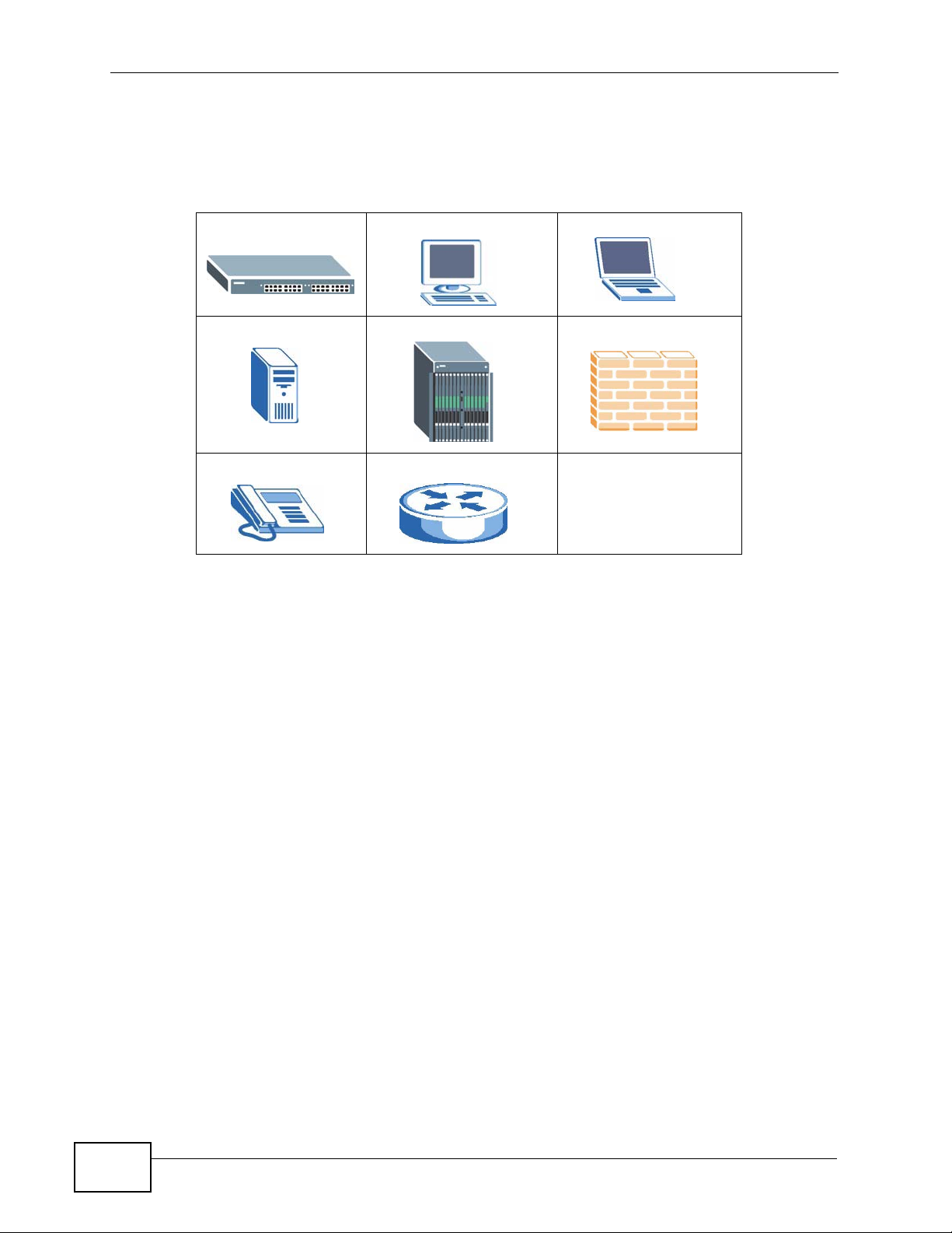
1.1.1 Backbone Application
The MES-2110 is an ideal solution for small networks where rapid growth can be
expected in the near future. The MES-2110 can be used standalone for a group of
heavy traffic users. You can connect computers and servers directly to the MES2110’s port or connect other switches to the MES-2110.
MES-2110 User’s Guide
19
Page 20
Chapter 1 Introduction
In this example, all computers can share high-speed applications on the server. T o
expand the network, simply add more networking devices such as switches,
routers, computers, print servers etc.
Figure 1 Backbone Application
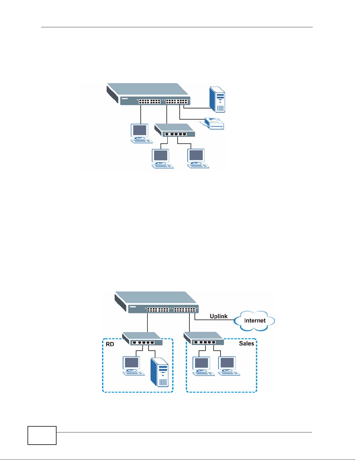
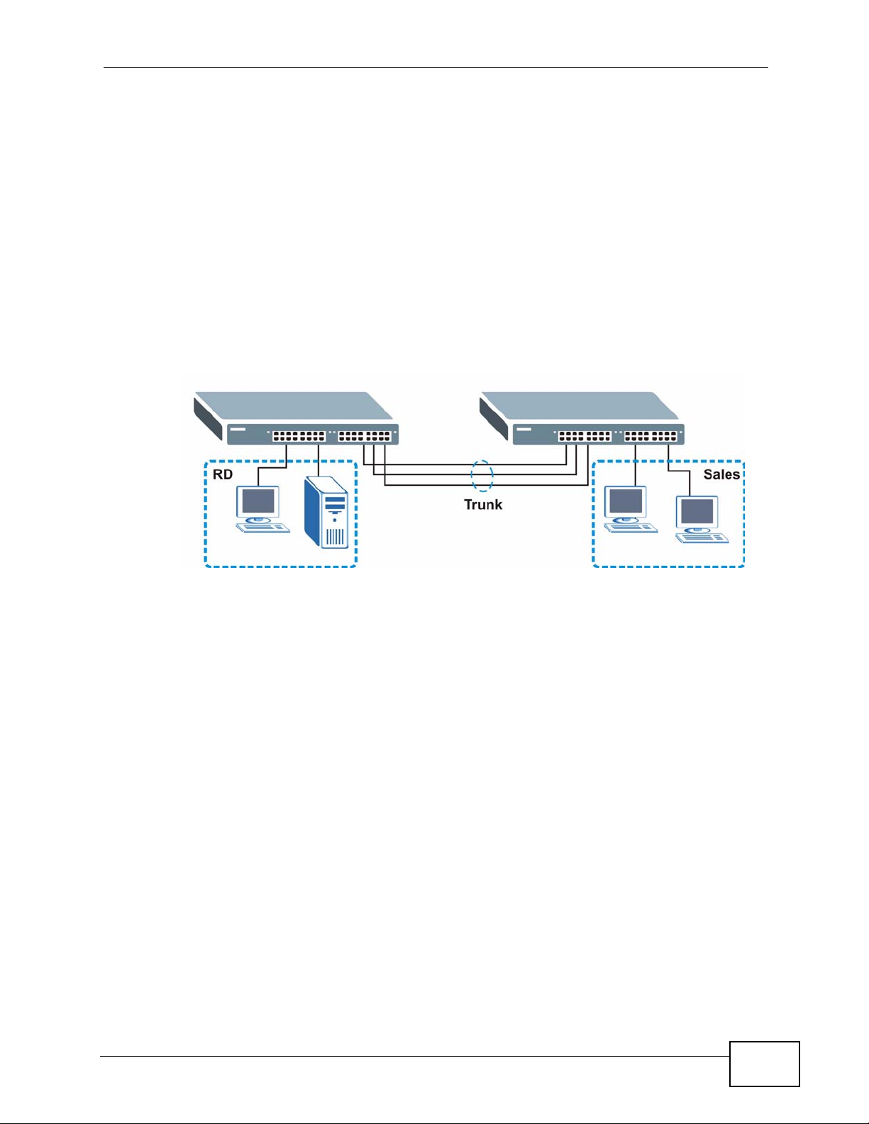
1.1.2 Bridging Example
In this example, the MES-2110 connects different company departments ( RD and
Sales) to the corporate backbone. It can alleviate bandwidth contention and
eliminate server and network bottlenecks. All users that need high bandwidth can
connect to high-speed department servers via the MES-2110. You can provide a
super-fast uplink connection by using a Gigabit Ethernet/mini-GBIC port on the
MES-2110.
Moreover, the MES-2110 eases supervision and maintenance by allowing network
managers to centralize multiple servers at a single location.
Figure 2 Bridging Application
20
MES-2110 User’s Guide
Page 21
1.1.3 High Performance Switching Example
The MES-2110 is ideal for connecting two networks that need high bandwidth. In
the following example, use trunking to connect these two networks.
Switching to higher-speed LANs such as ATM (Asynchronous Transmission Mode)
is not feasible for most people due to the expense of replacing all existing
Ethernet cables and adapter cards, restructuring your network and complex
maintenance. The MES-2110 can provide the same bandwidth as ATM at much
lower cost while still being able to use existing adapters and switches. Moreover,
the current LAN structure can be retained as all ports can freely communicate with
each other.
Figure 3 High Performance Switched Workgroup Application
Chapter 1 Introduction
1.1.4 IEEE 802.1Q VLAN Application Examples
A VLAN (Virtual Local Area Network) allows a physical network to be partitioned
into multiple logical networks. Stations on a logical network belong to one group.
A station can belong to more than one group. With VLAN, a station cannot directly
talk to or hear from stations that are not in the same group(s) unless such traffic
first goes through a router.
For more information on VLANs, refer to Chapter 12 on page 97.
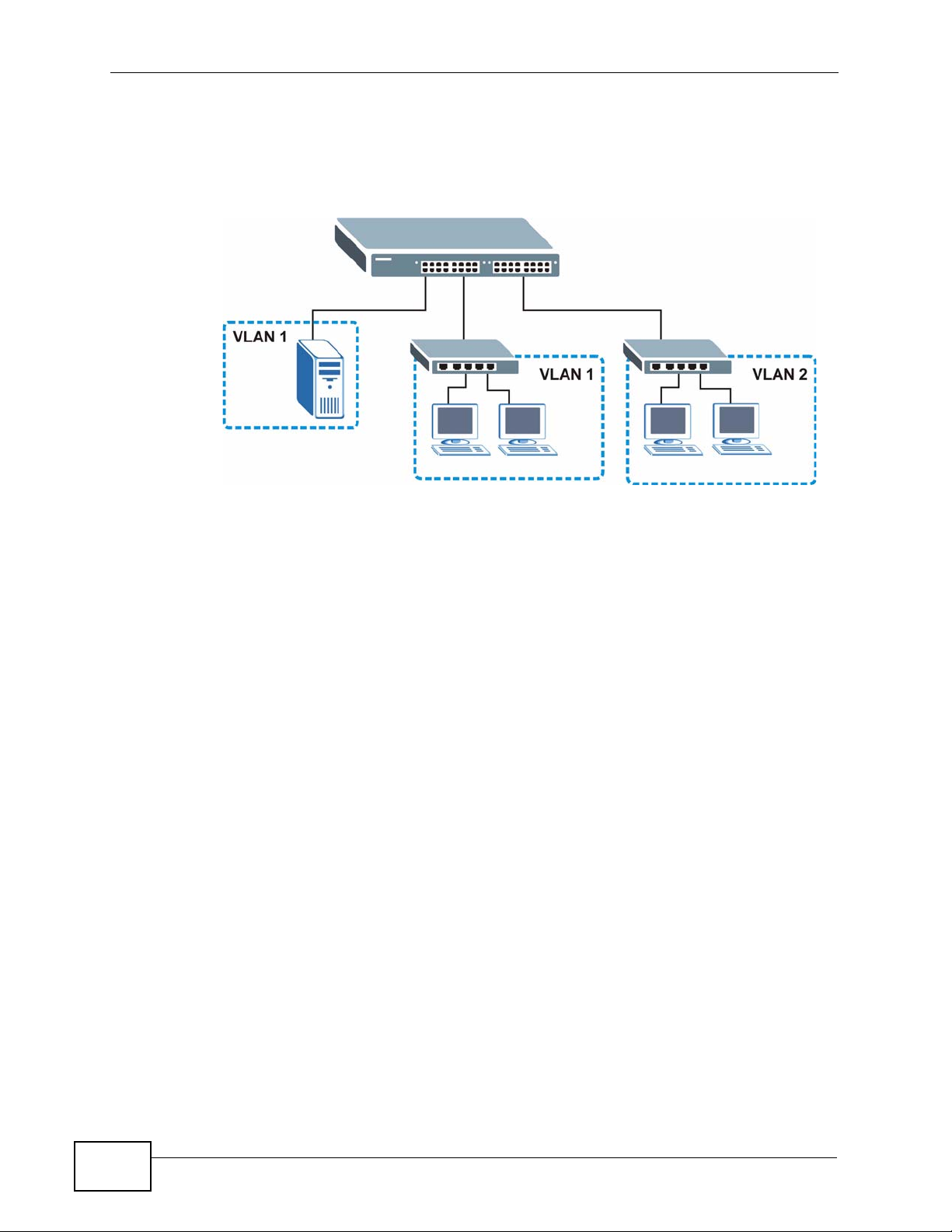
1.1.4.1 Tag-based VLAN Example
Ports in the same VLAN group share the same frame broadcast domain thus
increase network performance through reduced broadcast traffic. VLAN groups
can be modified at any time by adding, moving or changing ports without any recabling.
MES-2110 User’s Guide
21
Page 22
Chapter 1 Introduction
Shared resources such as a server can be used by all ports in the same VLAN as
the server. In the following figure only ports that need access to the server need
to be part of VLAN 1. Ports can belong to other VLAN groups too.
Figure 4 Shared Server Using VLAN Example
1.1.5 Metro Ethernet
The MES-2110 is ideal for connecting users to an Ethernet network that spans a
metropolitan area.
In the following example, the MES-2110 is one of many switches that connect
users in the metropolitan area to the Internet. The metro ethernet is based on a
star (or hub-and-spoke) topology, though other topologies, such as ring or mesh,
are also possible. The MES-2110 is connected to the backbone and the
22
MES-2110 User’s Guide
Page 23
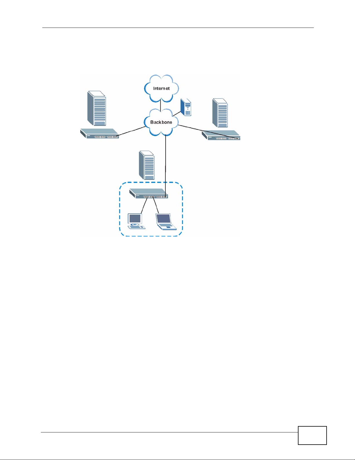
Chapter 1 Introduction
metropolitan servers over an optical network that provides higher bandwidth than
copper.
Figure 5 Metro Ethernet
1.2 Ways to Manage the MES-2110
Use any of the following methods to manage the MES-2110.
• Web Configurator. This is recommended for everyday management of the MES2110 using a (supported) web browser. See Chapter 5 on page 51.
• Command Line Interface. Line commands offer an alternative to the web
configurator and in some cases are necessary to configure advanced features.
See the CLI Reference Guide.
• SNMP. The MES-2110 can be monitored by an SNMP manager. See Section 22.3
on page 166.
MES-2110 User’s Guide
23
Page 24

Chapter 1 Introduction
1.3 Good Habits for Managing the MES-2110
Do the following things regularly to make the MES-2110 more secure and to
manage the MES-2110 more effectively.
• Change the password. Use a password that’s not easy to guess and that consists
of different types of characters, such as numbers and letters.
• Write down the password and put it in a safe place.
• Back up the configuration (and make sure you know how to restore it).
Restoring an earlier working configuration may be useful if the device becomes
unstable or even crashes. If you forget y our password, you will hav e to reset the
MES-2110 to its factory default settings. If you backed up an earlier
configuration file, you would not have to totally re-configure the MES-2110. You
could simply restore your last configuration.
24
MES-2110 User’s Guide
Page 25

CHAPTER 2
Hardware Installation and
Connection
2.1 Installation Scenarios
This chapter shows you how to install and connect the MES-2110.
The MES-2110 can be placed on a desktop or rack-mounted on a standard EIA
rack. Use the rubber feet in a desktop installation and the brackets in a rackmounted installation.
Note: For proper ventilation, allow at least 4 inches (10 cm) of clearance at the front
and 3.4 inches (8 cm) at the back of the MES-2110. This is especially important
for enclosed rack installations.
2.2 Desktop Installation Procedure
1 Make sure the MES-2110 is clean and dry.
2 Set the MES-2110 on a smooth, level surface strong enough to support the weight
of the MES-2110 and the connected cables. Make sure there is a power outlet
nearby.
3 Make sure there is enough clearance around the MES-2110 to allow air circulation
and the attachment of cables and the power cord.
4 Remove the adhesive backing from the rubber feet.
MES-2110 User’s Guide
25
Page 26
Chapter 2 Hardware Installation and Connection
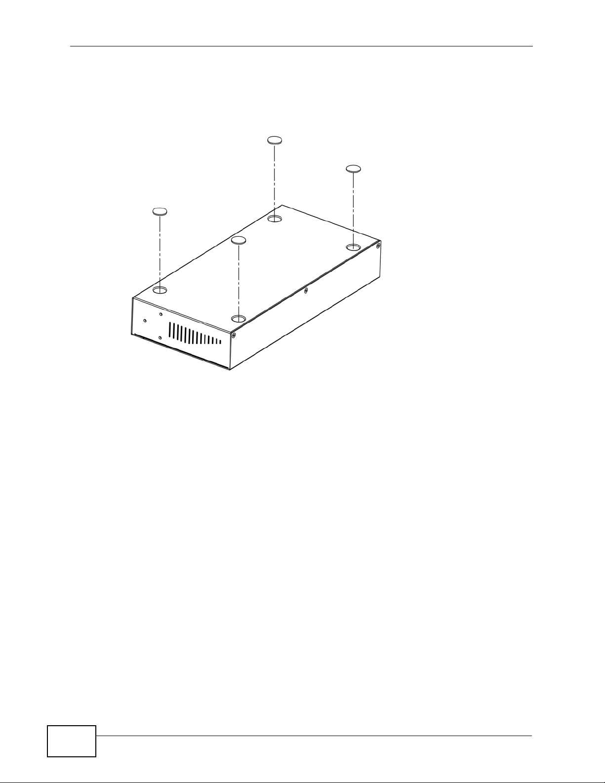
5 Attach the rubber feet to each corner on the bottom of the MES-2110. These
rubber feet help protect the MES-2110 from shock or vibration and ensure space
between devices when stacking.
Figure 6 Attaching Rubber Feet
Note: Do NOT block the ventilation holes. Leave space between devices when
stacking.
2.3 Mounting the MES-2110 on a Rack
The MES-2110 can be mounted on an EIA standard size, 19-inch rack or in a
wiring closet with other equipment. Follow the steps below to mount your MES2110 on a standard EIA rack using a rack-mounting kit.
Note: The following sections feature the AC model of the MES-2110 but are equally
applicable to the DC model.
2.3.1 Rack-mounted Installation Requirements
• Two mounting brackets.
• Eight M3 flat head screws and a #2 Philips screwdriver.
• Four M5 flat head screws and a #2 Philips screwdriver.
Failure to use the proper screws may damage the unit.
26
MES-2110 User’s Guide
Page 27
Chapter 2 Hardware Installation and Conn ec t ion
2.3.1.1 Precautions
• Make sure the rack will safely support the combined weight of all the equipment
it contains.
• Make sure the position of the MES-2110 does not make the rack unstable or
top-heavy. Take all necessary precautions to anchor the rack securely before
installing the unit.
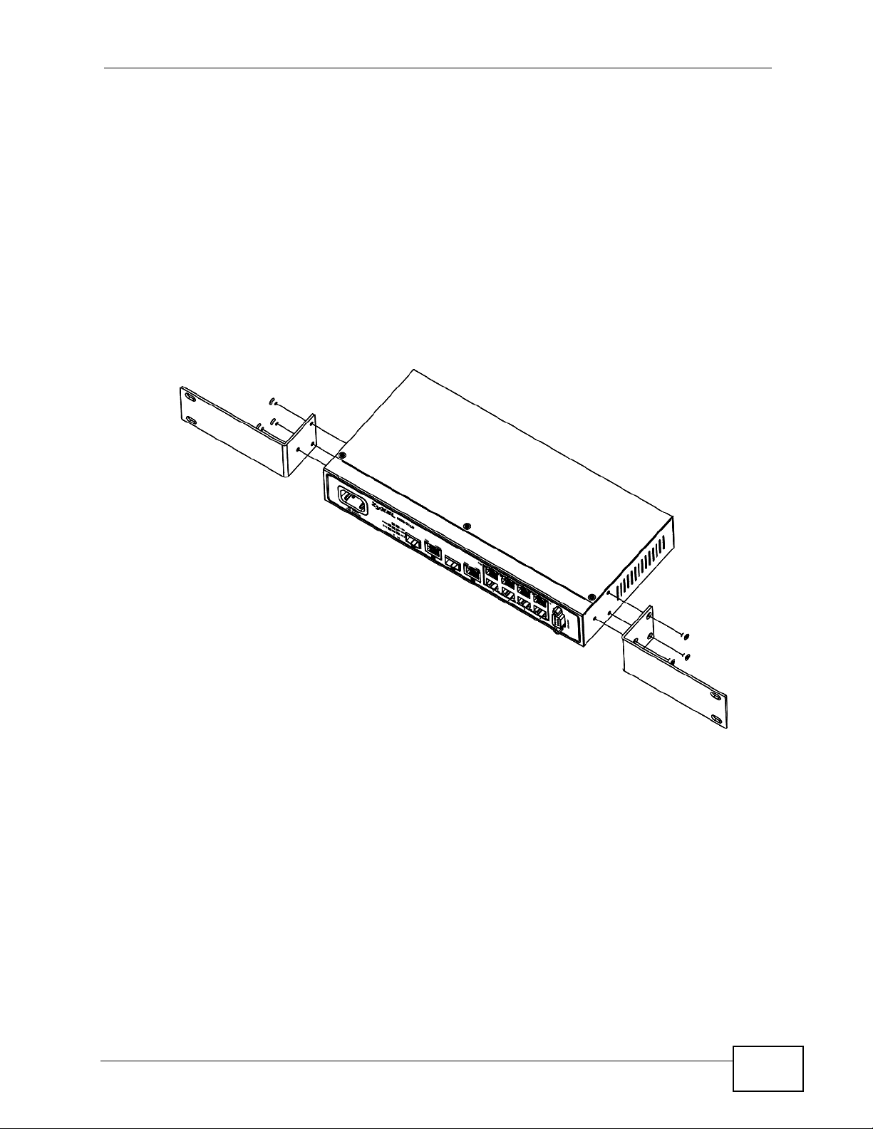
2.3.2 Attaching the Mounting Brackets to the MES-2110
1 Position a mounting bracket on one side of the MES-2110, lining up the four screw
holes on the bracket with the screw holes on the side of the MES-2110.
Figure 7 Attaching the Mounting Brackets
2 Using a #2 Philips screwdriver, install the M3 flat head screws through the
mounting bracket holes into the MES-2110.
3 Repeat steps 1 and 2 to install the second mounting bracket on the other side of
the MES-2110.
4 You may now mount the MES-2110 on a rack. Proceed to the next section.
MES-2110 User’s Guide
27
Page 28
Chapter 2 Hardware Installation and Connection
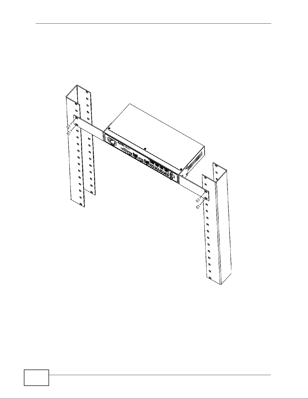
2.3.3 Mounting the MES-2110 on a Rack
1 Position a mounting bracket (that is already attached to the MES-2110) on one
side of the rack, lining up the two screw holes on the brack et with the screw holes
on the side of the rack.
Figure 8 Mounting the MES-2110 on a Rack
28
2 Using a #2 Philips screwdriver, install the M5 flat head screws through the
mounting bracket holes into the rack.
3 Repeat steps 1 and 2 to attach the second mounting bracket on the other side of
the rack.
MES-2110 User’s Guide
Page 29
CHAPTER 3
Hardware Overview
This chapter describes the front panel and rear panel of the MES-2110 and shows
you how to make the hardware connections.
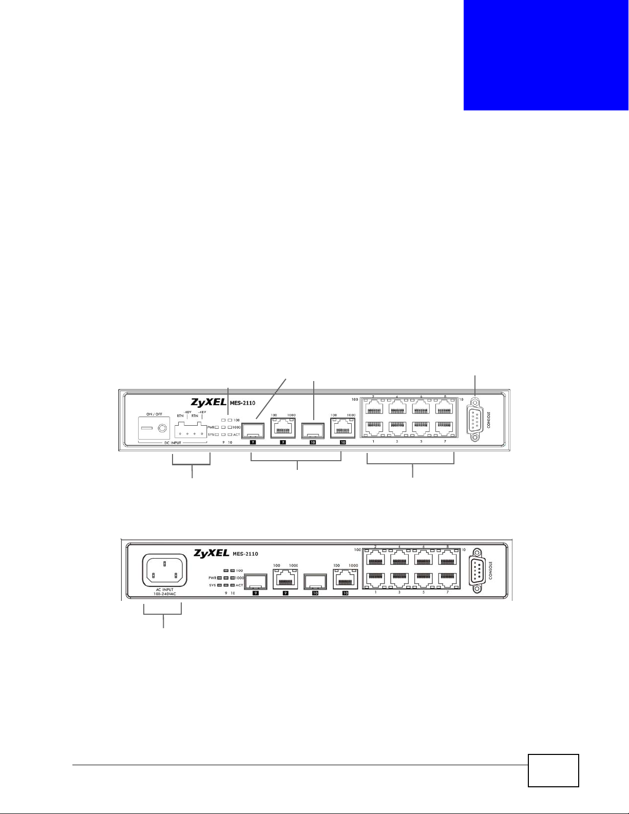
3.1 Front Panel
The following figure shows the front panel of the MES-2110.
Figure 9 Front Panel
DC Terminal
Block Header
AC Power Connection
LEDs
Mini-GBIC slots
Dual Personality
Interfaces
Console Port
Ethernet
Ports
MES-2110 User’s Guide
29
Page 30
Chapter 3 Hardware Overview
The following table describes the port labels on the front panel.
Table 1 Front Panel Connections
LABEL DESCRIPTION
Power
Connection
8 10/100
Mbps RJ-45
Ethernet
Ports
Two MiniGBIC Slots
Two Dual
Personality
Interfaces
Console Port The console port is for local configuration of the MES-2110.
Connect an appropriate power supply to this port.
Connect these ports to a computer, a hub, an Ethernet switch or router.
Use mini-GBIC transceivers in these slots for fiber-optic or copper
connections to backbone Ethernet switches.
Each interface has one 1000 Base-T copper RJ-45 port and one mini-GBIC
slot, with one port active at a time.
• 10/100/1000 Mbps RJ-45 GbE Ports:
Connect these Gigabit Ethernet ports to high-bandwidth backbone
network Ethernet switches.
•Mini-GBIC Slots:
Use mini-GBIC transceivers in these slots for fiber-optic or copper
connections to backbone Ethernet switches.
3.1.1 Console Port
For local management, you can use a computer with terminal emulation software
configured to the following parameters:
• VT100
• Terminal emulation
• 9600 bps
• No parity, 8 data bits, 1 stop bit
• No flow control
Connect the male 9-pin end of the console cable to the console port of the MES-
2110. Connect the female end to a serial port (COM1, COM2 or other COM port) of
your computer.
3.1.2 Gigabit Ethernet Ports
The MES-2110 has 1000Base-T auto-negotiating, auto-crossover Ethernet ports.
In 10/100/1000 Mbps Fast Ethernet, the speed can be 10 Mbps, 100 Mbps or 1000
Mbps and the duplex mode can be half duplex or full duplex.
30
An auto-negotiating port can detect and adjust to the optimum Ethernet speed
(10/100/1000 Mbps) and duplex mode (full duplex or half duplex) of the
connected device.
MES-2110 User’s Guide
Page 31

An auto-crossover (auto-MDI/MDI-X) port automatically works with a straightthrough or crossover Ethernet cable.
Two of the 1000Base-T Ethernet ports are paired with a mini-GBIC slot to create a
dual personality interface. The MES-2110 uses up to one connection for each miniGBIC and 1000Base-T Ethernet pair. The mini-GBIC slots have priority over the
Gigabit ports. This means that if a mini-GBIC slot and the corresponding GbE port
are connected at the same time, the GbE port will be disabled.
When auto-negotiation is turned on, a Ethernet port negotiates with the peer
automatically to determine the connection speed and duplex mode. If the peer
Ethernet port does not support auto-negotiation or turns off this feature, the MES2110 determines the connection speed by detecting the signal on the cable and
using half duplex mode. When the MES-2110’s auto-negotiation is turned off, an
Ethernet port uses the pre-configured speed and duplex mode when making a
connection, thus requiring you to make sure that the settings of the peer Ethernet
port are the same in order to connect.
3.1.2.1 Default Ethernet Negotiation Settings
Chapter 3 Hardware Overview
The factory default negotiation settings for the Gigabit ports on the MES-2110
are:
• Speed: Auto
•Duplex: Auto
• Flow control: Off
•Link Aggregation: Disabled
3.1.2.2 Auto-crossover
All ports are auto-crossover, that is auto-MDIX ports (Media Dependent Interface
Crossover), so you may use either a straight-through Ethernet cable or crossover
Ethernet cable for all Gigabit port connections. Auto-crossover ports automatically
sense whether they need to function as crossover or straight ports, so crossover
cables can connect both computers and switches/hubs.
3.1.3 Mini-GBIC Slots
These are slots for mini-GBIC (Gigabit Interface Converter) transceivers. A
transceiver is a single unit that houses a transmitter and a receiver. The MES-2110
does not come with transceivers. You must use transceivers that comply with the
Small Form-factor Pluggable (SFP) Transceiver MultiSource Agreement (MSA). See
the SFF committee’s INF-8074i specification Rev 1.0 for details.
MES-2110 User’s Guide
31
Page 32

Chapter 3 Hardware Overview
You can change transceivers while the MES-2110 is operating. You can use
different transceivers to connect to Ethern et switches with different types of fiberoptic or even copper cable connectors.
To avoid possible eye injury, do not look into an operating fiberoptic module’s connectors.
• Type: SFP connection interface
• Connection speed: 1 Gigabit per second (Gbps)
3.1.3.1 Transceiver Installation
Use the following steps to install a mini-GBIC transceiver (SFP module).
1 Insert the transceiver into the slot with the exposed section of PCB board facing
down.
2 Press the transceiver firmly until it clicks into place.
3 The MES-2110 automatically detects the installed transceiver. Check the LEDs to
verify that it is functioning properly.
4 Close the transceiver’s latch (latch styles vary).
5 Connect the fiber optic cables to the transceiver.
Figure 10 Transceiver Installation Example
Figure 11 Connecting the Fiber Optic Cables
3.1.3.2 Transceiver Removal
32
Use the following steps to remove a mini-GBIC transceiver (SFP module).
1 Remove the fiber optic cables from the transceiver.
2 Open the transceiver’s latch (latch styles vary).
MES-2110 User’s Guide
Page 33

3 Pull the transceiver out of the slot.
Figure 12 Removing the Fiber Optic Cables
Figure 13 Opening the Transceiver’s Latch Example
Figure 14 Transceiver Removal Example
Chapter 3 Hardware Overview
3.2 Power Connections Overview
Use the following procedures to connect the MES-2110 to a power source after
you have installed it.
Note: Check the power supply requirements in Chapter 25 on page 215, and make
sure you are using an appropriate power source.
Keep the power supply switch and the MES-2110’ s power switch in
the OFF position until you come to the procedure for turning on
the power.
Use only power wires of the required diameter for connecting the MES2110 to a power supply.
MES-2110 User’s Guide
33
Page 34

Chapter 3 Hardware Overview
3.2.1 AC Power Connection
Note: This is only for the AC model of the MES-2110.
Connect the female end of the power cord to the power socket of your MES-2110.
Connect the other end of the cord to a power outlet. Make sure that no objects
obstruct the airflow of the fans.
3.2.2 DC Power Connection
Note: This is only for the DC model of the MES-2110.
The MES-2110 uses a single ETB series terminal block plug with four pins which
allows you to connect up to two separate power supplies. If one power supply fails
the system can operate on the remaining power supply. Use two wires to connect
to a single terminal pair, one wire for the positive terminal and one wire for the
negative terminal.
Note: The current rating of the power wires must be greater than 20 Amp s. The power
supply to which the MES-2110 connects must have a built-in circuit breaker or
switch to toggle the power.
Note: When installing the power wire, push it wire firmly into the terminal as deep as
possible and make sure that no exposed (bare) wire can be seen or touched.
An exposed wire from a DC power source can be dangerous. Use
extreme care when connecting a DC power source to the device.
To connect a power supply:
1 Use a screwdriver to loosen the terminal block captive screws.
2 Connect one end of a power wire to the MES-2110’s RTN ( return) pi n and t ighten
the captive screw.
3 Connect the other end of the power wire to the positive terminal on the power
supply.
4 Connect one end of a power wire to the MES-2110’s -48V (input) pin and tighten
the captive screw.
34
5 Connect the other end of the power wire to the negative terminal on the power
supply.
6 Insert the terminal block plug in the MES-2110’s terminal block header.
MES-2110 User’s Guide
Page 35

3.2.3 Powering on the MES-2110
1 Turn on the power supply first.
2 Turn on the MES-2110’s power second.
3.3 LEDs
After you connect the power to the MES-2110, view the LEDs to ensure proper
functioning of the MES-2110 and as an aid in troubleshooting.
Table 2 LED Descriptions
LED COLOR
PWR Green On The system is turned on.
SYS Green On The system is on and functioning properly.
STATU
S
Off The system is off.
DESCRIPTION
Chapter 3 Hardware Overview
Blinking The system is rebooting and performing self-diagnostic
tests.
Off The power is off or the system is not ready/malfunctioning.
Ethernet Ports
LINK/
ACT
Mini-GBIC Slots
LNK Green On The link to this port is up.
ACT Green On The link to an Ethernet network is on.
1000Base-T Ethernet Ports (in Dual Personality Interface)
Green Blinking The system is transmitting/receiving to/from a 10 Mbps
Ethernet network.
On The link to a 10 Mbps Ethernet network is up.
Amber Blinking The system is transmitting/receiving to/from a 100 Mbps
Ethernet network.
On The link to a 100 Mbps Ethernet network is up.
Off The link to an Ethernet network is down.
Off The link to this port is not connected.
Blinking This port is receiving or transmitting data.
Off The port is not receiving or transmitting data.
MES-2110 User’s Guide
35
Page 36

Chapter 3 Hardware Overview
Table 2 LED Descriptions (continued)
LED COLOR
ACT Green Blinking The system is transmitting/receiving to/from a 10 Mbps or
Amber Blinking The system is transmitting/receiving to/from a 100 Mbps
STATU
S
On The link to a 10 Mbps or a 1000 Mbps Ethernet network is
On The link to a 100 Mbps Ethernet network is up.
Off The link to an Ethernet network is down.
DESCRIPTION
a 1000 Mbps Ethernet network.
up.
Ethernet network.
36
MES-2110 User’s Guide
Page 37

CHAPTER 4
Tutorials
4.1 IGMP Snooping
IGMP snooping allows a layer-2 device such as the MES-2110 to eavesdrop on
IGMP-based data packets traversing t he communications channel on la y er-3. This
allows it to determine which ports s hould specifically receive multicast traffic in
order to prevent multicasting flooding across all of its ports.
This tutorial shows you how to enable IGMP snooping, set IGMP to automatic
query mode, and then set port 10 to static.
To configure IGMP snooping:
1
2
3
4
5
1 In the Web Configurator, open the Configuration > IGMP Menu > IGMP
Configuration screen.
2 Set IGMP Snooping to Enable.
MES-2110 User’s Guide
37
Page 38

Chapter 4 Tutorials
3 Set IGMP Query Mode to Auto.
4 Set the Static Query field for port 10 to Enable.
5 Click Apply. The new settings appear in the IGMP Status table.
6 Click Save Settings in the navigation panel to store the changes permanently.
4.2 RADIUS Configuration
RADIUS is a protocol explicitly designed to manage single location au thentication
and authorization for an entire network. It also provides accounting services for
client usage of network resources.
This tutorial shows you how to set up one RADIUS server (172.16.10.10) and a
shared secret key (“hello”) for authentication.
To assign a RADIUS server to the MES-2110:
1 Open the Configuration > VLAN Menu > VLAN Type menu, set VLAN Type to
Tag-Based(802.1q), then click Apply.
38
MES-2110 User’s Guide
Page 39

Chapter 4 Tutorials
2 On the Configuration > VLAN Menu > Tag-Based(802.1q) > Tag-Based
info. screen, add VLAN ID 99 and click Apply. The new VLAN ID appears in the
Tag VLAN Status table.
3 Open the Configuration > 802.1x > Global Configuration screen. For the
802.1x option, select Enable. For the Guest VLAN option, select Enable and
enter 99 in the associated field. Click Apply to save these changes.
MES-2110 User’s Guide
39
Page 40

Chapter 4 Tutorials
4 Next go to the Configuration > 802.1x > RADIU S Server Configuration
screen. For Server IP Address, enter 172.16.10.10 and for Shared Server Key
enter hello, then click Apply.
5 Finally, open the Configuration > 802.1x > Port Configuration screen. From
the Port Number menu select Port 1 if not already selected, set the Guest
VLAN option to Enable, and click Apply.
40
MES-2110 User’s Guide
Page 41

6 Click Save Settings in the navigation panel to store the changes permanently.
4.3 MVR Configuration
MVR manages multicast traffic from an upstream VLAN on a multicast server to
downstream subscribers in the same VLAN group. This allows you to regulate
bandwidth by not streaming multicast traffic to every device on your network but
rather just to the intended computers.
Chapter 4 Tutorials
This tutorial shows you set up a Multicast VLAN R egistration (MVR) group and then
direct all multicast traffic with matching VLAN IDs to it.
For the purposes of this tutorial, use the following settings:
Table 3 MVR Tutorial Values
SETTING VALUE
VLAN Name StreamVlan
VLAN ID 100
Source Port 9
Receiver Ports 1-4, 10
Multicast Group Mode Dynamic
Tagging Ports 9, 10
Multicast Group IP Addresses 223.3.3.1 ~ 223.3.3.10
Multicast Group ID 1
Note: Make sure your Configuration > VLAN Menu > VLAN Type is set to Tag-
Based(802.1q) before proceeding.
MES-2110 User’s Guide
41
Page 42

Chapter 4 Tutorials
To configure MVR:
4
5
2
6
1
10
3
7
8
9
1 Open the Configuration > IGMP Menu > MVR screen.
2 Select Active to enable the MVR feature.
3 Enter StreamVlan as the MVR Name.
4 Enter 100 as the Multicast VLAN ID.
5 Set the MVR Mode to Dynamic.
6 In the Source Port column, deselect all ports except Port 9. This will be the
source port which receives all incoming multicasts from upstream.
7 In the Receiver Port column, select Ports 1-4 and Port 10. These ports are now
the designated downstream recipients for all incoming multicasts.
8 In the Tagging column, enable tagging for Port 9 and 10.
9 Click Apply to store these changes.
10 Click the Group Configuration link.
42
MES-2110 User’s Guide
Page 43

Chapter 4 Tutorials
11 In the Group Configuration screen, select the Multicast VLAN ID you created
in step 4 from the list. In this example, it is VLAN ID 100.
11
12
12 Enter a Group ID of 1, a Start Address of 227.3.3.1, and a Quantity of 10.
13 Click Add, then click Save Settings in the navigation panel to store the changes
permanently.
MES-2110 User’s Guide
43
Page 44

Chapter 4 Tutorials
4.4 VLAN ID Priority
This tutorial assigns port 1 as a tagged port for VLAN 1 and sets the priority of all
incoming packets from VLAN 1 to priority 3.
Note: Make sure your Configuration > VLAN Menu > VLAN Type is set to Tag-
Based(802.1q) before proceeding.
To configure VLAN ID priority:
3
4
1
2
5
6
1 Open the Configuration > VLAN Menu > Tag-Based(802.1q) > Tag-Based
info. screen.
2 For VLAN ID, sele ct Add from the menu and enter 2 in the associated field.
3 Set the Priority to 1.
4 For Pri-Overide, select Enable.
5 In the Member column for Port 1, select Tagging.
6 Click Apply.
44
MES-2110 User’s Guide
Page 45

7 Click Save Settings in the navigation panel to store the changes permanently.
4.5 Untrusted ARP Inspection
This tutorial shows you how to assign port 1 to 8 as untrusted for ARP inspection.
Generally if you want to enable ARP inspection on the device you also have to
enable DHCP snooping first to build a binding table.
Chapter 4 Tutorials
To set up ARP inspection:
1 Open the Configuration > IP Source Guard > DHCP > DHCP Snooping
Configuration screen.
1
2
MES-2110 User’s Guide
3
45
Page 46

Chapter 4 Tutorials
2 Set Action to Enable and DHCP Snooping VLAN Mode to All-VLAN.
3 Click Apply.
4 Open the Configuration > IP Source Guard > ARP Inspection > ARP
Inspection Configuration screen.
4
5
7
6
8
5 Set Action to Enable and ARP Inspection VLAN Mode to All-VLAN.
6 In the Trust column, select Port 9 and Port 10.
7 In the Untrust column, select Ports 1-8.
8 Click Apply.
9 Click Save Settings in the navigation panel to store the changes permanently.
46
MES-2110 User’s Guide
Page 47

4.6 Outgoing Traffic Bandwidth
This tutorial shows you how to set the outgoing traffic bandwidth limit to 1 Mbps
for Port 2.
To configure outgoing traffic bandwidth:
2
3
Chapter 4 Tutorials
1
4
1 Open the Configuration > Bandwidth Control screen.
2 Set the Port Number to Port 2.
3 In the Egress row, set the Rate Level to 1M~100M (1M+), the Rate Limit to
1000 k, and the Active option to Enable.
4 Click Apply.
5 Click Save Settings in the navigation panel to store the changes permanently.
MES-2110 User’s Guide
47
Page 48

Chapter 4 Tutorials
4.7 Frame Tagging
In this tutorial, shows you how to configure ports 1 and 2 on the switch to tag
incoming frames with the service provider’s VID of 37 (ports are connected to
customer A network) and how to set the priority for ports 1 and 2 to 3.
The scenario is that both A and B are Service Provider’s Network (SPN) customers
with VPN tunnels between their head offices and branch offices respectively. Both
have an identical VLAN tag for their VLAN group. The service provider can
separate these two VLANs within its network by adding tag 37 to distinguish
customer A and tag 48 to distinguish customer B at edge device x and then
stripping those tags at edge device y as the data frames leave the network.
Figure 15 Frame Tagging Example
48
MES-2110 User’s Guide
Page 49

To configure frame tagging:
2
Chapter 4 Tutorials
1
3
4
1 Open the Configuration > VLAN Menu > Tag-Based(802.1q) > VLAN
Stacking screen.
2 Select Active and click Apply.
3 For Port 1 and Port 2, use the following settings: for Role select Access, for
PVID use 37 and for Priority choose 1.
Note: If the port for which you are configuring frame taggin g is the same port by wh ich
you connect to the MES-21 10 th en your computer should use the same PVID or
you should switch a non-tagged port.
4 Click Apply.
5 Click Save Settings in the navigation panel to store the changes permanently.
MES-2110 User’s Guide
49
Page 50

Chapter 4 Tutorials
50
MES-2110 User’s Guide
Page 51

CHAPTER 5
The Web Configurator
5.1 Introduction
This section introduces the configuration and functions of the web configurator.
The web configurator is an HTML-based management interface that allows easy
MES-2110 setup and management via Internet browser. Use Internet Explorer 6.0
and later or Firefox 1.5 and later versions. The recommended screen resolution i s
1024 by 768 pixels.
In order to use the web configurator you need to allow:
• Web browser pop -up windows from your device. W eb pop-up blocking i s enabled
by default in Windows XP SP (Service Pack) 2.
• JavaScript (enabled by default).
• Java permissions (enabled by default).
5.2 System Login
1 Start your web browser.
2 Type “http://” and the IP address of the MES-2110 (for example, the default is
192.168.1.1) in the Location or Address field. Press [ENTER].
MES-2110 User’s Guide
51
Page 52

Chapter 5 The Web Configurator
3 The login screen appears. Enter the user name (admin by default) and password
(1234 by default).
Figure 16 Web Configurator: Login
4 Click OK to view the first web configurator screen.
52
MES-2110 User’s Guide
Page 53

5.3 The Main Screen
The Main screen is the first screen that displays when you access the web
configurator.
The following figure shows the navigating components of a web configurator
screen.
Figure 17 Web Configurator Main Screen
A
Chapter 5 The Web Configurator
A - Click the menu items to open submenu links, and then click on a submenu link
to open the screen in the main window.
MES-2110 User’s Guide
53
Page 54

Chapter 5 The Web Configurator
In the navigation panel, click a main link to reveal a list of submenu links.
Table 4 Navigation Panel Sub-links Overview
SYSTEM DETAILS CONFIGURATION MGMT CONFIG
SYSTEM RESTART
MENU
54
MES-2110 User’s Guide
Page 55

Chapter 5 The Web Configurator
The following table lists the various web configurator screens within the sub-links.
Table 5 Web Configurator Screen Sub-links Details
SYSTEM DETAILS CONFIGURATION MGMT CONFIG
System Info.
Port Configuration
Serial Port Config
SYSTEM
RESTART
MENU
Restart Option
Board Info.
DHCP Config
Port Status
Rmon Status
Loop Detection
Jumbo Frame
802.1
Global Configuration
RADIUS Server Configuration
Port Configuration
802.1x Status
Bridge Menu
Bridge Config
RSTP System Config
RSTP Per Port Config
VLAN Menu
VLAN Type
Port-Based
Tag-Based (802.1q)
VLAN Stacking
Port Info.
Tag-Based Info.
Management VLAN
Bandwidth Control
SNMP Config
SNMP
Communities
IP Trap Manager
SNTP
Email Alarm & SYSLog
User Config
Cable Test
Host Denial-of-Service
Protection
Port Abnormal Traffic
Detection
Firmware Download
Configuration File
MES-2110 User’s Guide
Storm Control
Port Mirroring
Trunk Config
Aggregator Setting
LACP Configuration
LACP Link Status
IGMP Menu
IGMP Config
IGMP Groups Status
MVR
55
Page 56

Chapter 5 The Web Configurator
DHCP Snooping
DHCP Snooping Config
DHCP Binding Table
ARP Inspection
MAC Menu
MAC Table Status
Lock Learning MAC
MAC Filter Config
MAC Limit Config
QoS Menu
Base Configuration
802.1p Priority
Tag Priority
IP DSCP Priority
Priority Override Configuration
The following table describes the links in the navigation panel.
Table 6 Navigation Panel Links
LINK DESCRIPTION
System Details
System
Info.
Board Info. This link takes you to a screen that shows hardware and firmware
DHCP
Config
Configuration
Port
Configurati
on
Port Status This link takes you to a screen that shows port settings for individual
Rmon
Status
Loop
Detection
Jumbo
Frame
802.1x This link takes you to a screen where you can configure IEEE 802.1x
Bridge
Menu
VLAN Menu This link takes you to screens where you can configure port-based or
This link takes you to a screen that displays general system information.
You can also configure general system information about the MES-2110.
information.
This link takes you to a screen where you can configure the DHCP
settings.
This link takes you to a screen where you can configure settings for
individual MES-2110 ports.
MES-2110 ports.
This link takes you to a screen where you can view statistics on the
traffic going through each port.
This link takes you to a screen where you can configure protection
against network loops that occur on the edge of your network.
This link takes you to a screen where you can configure Jumbo frames or
Ethernet frames with a payload greater than 1500 bytes.Use this screen
to configure the jumbo frame size.
authentication.
This link takes you to screens where you can configure the RSTP to
prevent network loops.
tag-based (802.1Q) VLAN (depending on what you configured in the
Switch Setup menu).
56
MES-2110 User’s Guide
Page 57

Chapter 5 The Web Configurator
Table 6 Navigation Panel Links (continued)
LINK DESCRIPTION
Bandwidth
Control
Storm
Control
Port
Mirroring
Trunk
Config
IGMP Menu This link takes you to screens where you can configure various multicast
DHCP
Snooping
ARP
Inspection
MAC Menu This link takes you to screens where you can configure the following
This link takes you to a screen where you can configure bandwidth limits
on the MES-2110.
This link takes you to a screen to set up broadcast filters.
This link takes you to a screen where you can copy traffic from one port
or ports to another port in order that you can examine the traffic from
the first port without interference.
This link takes you to screens where you can logically aggregate physical
links to form one logical, higher-bandwidth link.
features, IGMP snooping and create multicast VLANs.
This link takes you to screens where you can configure filtering of
unauthorized DHCP frames in your network.
This link takes you to a screen where you can configure filtering of
unauthorized Address Resolution Protocol (ARP) frames in your network.
settings:
• configure IEEE 802.1x port authentication as well as MAC
authentication for clients communicating via the MES-2110,
• activate MAC address learning and set the maximum number of MAC
addresses to learn on a port,
• view the MAC addresses (and types) of devices attached to what
ports.
QoS Menu This link takes you to screens where you can configure priority levels for
traffic transmitted through each port.
Mgmt Config
Serial Port
Config
SNMP
Config
SNTP This link takes you to a screen where you can configure SNTP and date/
Email
Alarm &
SYSLog
User Config This link takes you to a screen where you can set up administrative and
Cable Test This link takes you to a screen where you can test the cable connection
Host
Denial-ofService
Protection
Port
Abnormal
Traffic
Detection
This link takes you to a screen where you can configure the parameters
for connections via the console port.
This link takes you to screens where you can configure settings for date
and time.
time settings.
This link takes you to screens where you can set up system logs and e-
mail the logs to you.
user accounts for people to use the MES-2110.
on each port.
This link takes you to a screen where you can allow trusted computers to
access the MES-2110 via remote management.
This link takes you to a screen where you can configure the MES-2110 to
detect abnormal traffic transmission and temporarily or permanently
block traffic transmission through a port.
MES-2110 User’s Guide
57
Page 58

Chapter 5 The Web Configurator
Table 6 Navigation Panel Links (continued)
LINK DESCRIPTION
Firmware
Download
Configurati
on File
System Restart Menu
Restart
Option
Save Settings This link takes you to a screen where you can sav e the changes you have
This link takes you to a screen where you can perform firmware
maintenance.
This link takes you to a screen where you can perform configuration file
maintenance.
This link takes you to a screen where you can reboot the system.
made on the MES-2110 and restart the MES-2110.
5.3.1 Set Up the Administrative Password
After you log in for the first time, it is recommended you set up an administrator
password. Click Mgmt Config > User Config to display the next screen. Enter a
password for the admin account and click Apply.
Figure 18 Configure Administrator Login Password
5.4 Saving Your Configuration
When you are done modifying the settings in a screen, click Apply to save your
changes back to the run-time memory. Settings in the run-time memory are lost
when the MES-2110’s power is turned off.
Click the Save Settings link in the navigation panel to save your configuration to
nonvolatile memory. Nonvolatile memory refers to the MES-2110’s storage that
remains even if the MES-2110’s power is turned off. If you don't use Save
Settings all configuration changes will only apply until you restart the MES-2110.
58
Note: Use the Save Settings link when you are done with a configuration session.
Note: After saving changes to the IP Address, Subnet Mask or Gateway settings, the
MES-2110 will need to reboot to put them into effect (after prompting you for
confirmation.)
MES-2110 User’s Guide
Page 59

5.5 Switch Lockout
You could block yourself (and all others) from using in-band-management
(managing through the data ports) if you do one of the following:
1 Delete the management VLAN (default is VLAN 1).
2 Delete all port-based VLANs with the CPU port as a member. The “CPU port” is the
management port of the MES-2110.
3 Filter all traffic to the CPU port.
4 Disable all ports.
5 Misconfigure the text configuration file.
6 Forget the password and/or IP address.
7 Prevent all services from accessing the MES-2110.
Chapter 5 The Web Configurator
8 Change a service port number but forget it.
Note: Be careful not to lock yourself and others out of the MES-2110. If you do lock
yourself out, try using out-of-band management (via the console port) to
configure the MES-2110.
5.6 Resetting the MES-2110
If you lock yourself (and others) from the MES-2110 or forget the administrator
password, you will need to reload the factory-default configur ation file or reset the
MES-2110 back to the factory defaults.
5.6.1 Reload the Configuration File
Uploading the factory-default configuration file replaces the current configuration
file with the factory-default configuration file. This means that you will lose all
previous configurations and the speed of the console port will be reset to the
default of 9600 bps with 8 data bits, no parity, one stop bit and flow control set to
none. The password will also be cleared and the IP address be set to
192.168.0.254.
To upload the configuration file, do the following:
1 Connect to the console port using a computer with terminal emulation software.
MES-2110 User’s Guide
59
Page 60

Chapter 5 The Web Configurator
2 Disconnect and reconnect the MES-2110’s power to begin a session. When you
reconnect the MES-2110’s power, you will see the initial screen.
3 When you see “Username:”, type admin and press [Enter].
4 Type the administrative password and press [Enter]. Simply press [Enter] if you
did not set up a password.
5 Type enable and press [Enter] to turn on administrative commands.
6 Type reset default and press [Enter] to restore the system to the factory
defaults. The MES-2110 will restart.
Figure 19 Resetting the MES-2110: Via the Console Port
Username: admin
Password:
MES-2110> enable
MES-2110# reset default
The MES-2110 is now reinitialized with a default configuration file.
60
MES-2110 User’s Guide
Page 61

CHAPTER 6
System Details
6.1 Overview
The System Details screens show general system information about the MES-
2110. You can also use the screens to configure system and DHCP client settings.
6.2 The System Information Screen
Click System Details > System Info. to open the following screen.
Figure 20 System Details > System Info.
MES-2110 User’s Guide
61
Page 62

Chapter 6 System Details
The following table describes the labels in this screen.
Table 7 System Details > System Info.
LABEL DESCRIPTION
Description This is the descriptive name of the MES-2110 for identification
Model Name This is the model name of the MES-2110.
Object ID An Object ID defines what trap the MES-2110 should send an
Up Time This shows how long the MES-2110 has been turned on.
System Name Choose a descriptive name for identification purposes. This name
Contact Name Enter the name of the person in charge of this MES-2110. Y ou can
Location Enter the geographic location of your MES-2110. You can use up
DHCP Client This shows whether the DHCP client is Enabled or Disabled. If
purposes.
SNMP Manager.
consists of up to 64 printable characters; spaces are allowed.
use up to 32 printable ASCII characters; spaces are allowed.
to 32 printable ASCII characters; spaces are allowed.
DHCP is disabled, you must enter an IP address, subnet mask and
gateway in the following fields. Otherwise, a DHCP server will
assign this information to the MES-2110.
See Section 6.4 on page 63 for details about configuring the
DHCP client.
IP Address Enter the IP address of your MES-2110 in dotted decimal notation
for example 192.168.1.1.
Subnet Mask Enter the IP subnet mask of your MES-2110 in dotted decimal
notation for example 255.255.255.0.
Gateway Enter the IP address of the default outgoing gateway in dotted
decimal notation, for example 192.168.1.254.
Undo Click this to restore your last saved settings.
Apply Click Apply to save your changes to the Zy XEL Device’s run-time
memory. The ZyXEL Device loses these changes if it is turned off
or loses power, so use the Save Settings link in the navigation
panel to save your changes to the non-volatile memory.
6.3 The Board Information Screen
Use this screen to view the hardware and firmware information. Click System
Details > Board Info. to open the following screen.
Figure 21 System Details > Board Info.
62
MES-2110 User’s Guide
Page 63

The following table describes the labels in this screen.
Table 8 System Details > Board Info.
LABEL DESCRIPTION
Hardware Version This is the version number of the MES-2110’s hardware.
Firmware Version This is the version number of the MES-2110’s current firmware
including the date and time that the firmware is created.
Port Number This shows the number of available ports on the MES-2110.
6.4 The DHCP Configuration Screen
Use this screen to turn on or off the DHCP client. Click System Details > DHCP
Config to open the following screen.
Figure 22 System Details > DHCP Config
Chapter 6 System Details
The following table describes the labels in this screen.
Table 9 System Details > DHCP Config
LABEL DESCRIPTION
DHCP Client Use this to turn the DHCP client on or off. Turn on the DHCP client
if you have a DHCP server that can assign the MES-2110 an IP
address, subnet mask and a default gateway IP address
automatically.
DHCP Client State This shows whether the DHCP client is Enabled or Disabled.
DHCP Leased Time This is how long ago the MES-2110 got an IP address from a
DHCP server (if DHCP client is enabled).
DHCP Expiry Time This is how long there is to go before the MES-2110 will get a new
IP address from a DHCP server (if DHCP client is enabled).
Undo Click this to restore your last saved settings.
Apply Click Apply to save your changes to the Zy XEL Device’s run-time
memory. The ZyXEL Device loses these changes if it is turned off
or loses power, so use the Save Settings link in the navigation
panel to save your changes to the non-volatile memory.
MES-2110 User’s Guide
63
Page 64

Chapter 6 System Details
Once you click the Apply button, the following message displays, reminding you
to save your settings in the Save Settings screen and reboot the MES-2110.
Figure 23 System Details > DHCP Config > Apply
64
MES-2110 User’s Guide
Page 65

CHAPTER 7
Configuration
7.1 Overview
The Configuration screens let you configure the MES-2110 settings.
7.2 The Port Configuration Screen
Use this screen to configure MES-2110 port settings. You can assign a unique
name to the ports, select its speed setting and
Click Configuration > Port Configuration to open the following screen.
enable or disable auto-negotiation.
Figure 24 Configuration > Port Configuration
MES-2110 User’s Guide
65
Page 66

Chapter 7 Configuration
The following table describes the labels in this screen.
Table 10 Configuration > Port Configuration
LABEL DESCRIPTION
Port This is the port number.
Name Enter a descriptive name that identifies this port. You can enter
Admin Use this to enable or disable administrative access through this
Speed Select the port’s current speed (10M for 10 Mbps and 100M for
Duplex Use this field to change the status to Half or Full duplex mode.
AUTO Use this to enable or disable auto-negotiation.
Flow-Control Use this to enable or disable flow control.
up to 64 alpha-numerical characters.
Note: Due to space limitation, the port name may be
truncated in some Web Configurator screens.
port.
100 Mbps). The speed for the fiber ports is fixed.
The duplex status for the fiber ports is fixed.
AUTO (auto-negotiation) allows one port to negotiate with a peer
port automatically to obtain the connection speed and duplex
mode that both ends support. When auto-negotiation is turned
on, a port on the MES-2110 negotiates with the peer
automatically to determine the connection speed and duplex
mode. If the peer port does not support auto-negotiation or turns
off this feature, the MES-2110 determines the connection speed
by detecting the signal on the cable and using half duplex mode.
When the MES-2110’s auto-negotiation is turned off, a port uses
the pre-configured speed and duplex mode when making a
connection, thus requiring you to make sure that the settings of
the peer port are the same in order to connect.
66
A concentration of traffic on a port decreases port bandwidth and
overflows buffer memory causing frame discards and frame
losses. Flow Control is used to regulate transmission of signals
to match the bandwidth of the receiving port.
The MES-2110 uses IEEE802.3x flow control in full duplex mode
and backpressure flow control in half duplex mode.
IEEE802.3x flow control is used in full duplex mode to send a
pause signal to the sending port, causing it to temporarily stop
sending signals when the receiving port memory buffers fill.
Back Pressure flow control is typically used in half duplex mode to
send a "collision" signal to the sending port (mimicking a state of
frame collision) causing the sending port to temporarily stop
sending signals and resend later.
Port This indicates the port number
Name This indicates the descriptive named assigned to the port.
Admin This indicates whether administrative access is enabled or
disabled for this port.
Speed This indicates the speed assigned to the port (10M for 10 Mbps
and 100M for 100 Mbps).
MES-2110 User’s Guide
Page 67

Table 10 Configuration > Port Configuration
LABEL DESCRIPTION
Duplex This indicates the port’s duplex mode (Half or Full).
AUTO This indicates whether auto-negotiation for this port is enabled or
disabled.
Flow-Control This indicates whether flow control for this port is enabled or
disabled.
Undo Click this to restore your last saved settings.
Apply Click Apply to save your changes to the Zy XEL Device’s run-time
memory. The ZyXEL Device loses these changes if it is turned off
or loses power, so use the Save Settings link in the navigation
panel to save your changes to the non-volatile memory.
7.3 The Port Status Screen
To view the port statistics, click Configuration > Port Status to display the
Status screen as shown next.
Chapter 7 Configuration
Figure 25 Configuration > Port Status
The following table describes the labels in this screen.
Table 11 Configuration > Port Status
LABEL DESCRIPTION
Port This identifies the Ethernet port.
Name This is the name you assigned to this port in the Configuration > Port
Configuration screen.
Type This is the type of connector for each port. Port 1-8 are RJ-45 ports for
Ethernet connections. Port 9-10 are Gigabit SFP ports for fiber
connections.
Admin This shows whether administrative access is Enabled or Disabled on the
port. When administrative access is disabled on the port, users cannot
manage the MES-2110 via that port.
MES-2110 User’s Guide
67
Page 68

Chapter 7 Configuration
Table 11 Configuration > Port Status (continued)
LABEL DESCRIPTION
Speed This is the port’s current speed (10M for 10 Mbps and 100M for 100
Mbps).
Duplex This is the the port’s duplex status (Half or Full).
Link This shows the port’s connection status.
AUTO This shows whether auto-negotiation is On or Off .
Flow-Control This shows whether flow control is Enabled or Disabled.
Port
Configuration
Click this to configure port settings in the Port Configuration screen.
7.4 The RMON Status Screen
Use this screen to view individual port statistics. Click Configuration > Rmon
Status to open the following screen.
Figure 26 Configuration > Rmon Status
68
The following table describes the labels in this screen.
Table 12 Configuration > Rmon Status
LABEL DESCRIPTION
Slot Number Use this to select the port number you are viewing.
Clear Click this to reset the statistics on this port to zero.
MES-2110 User’s Guide
Page 69

Chapter 7 Configuration
Table 12 Configuration > Rmon Status (continued)
LABEL DESCRIPTION
RX
The following fields show detailed information about frames received.
InUnicasts This field shows the number of good unicast frames received.
InBroadcasts This field shows the number of good broadcast frames received.
InPause This field shows the number of 802.3x Pause frames received.
InMulticasts This field shows the number of good multicast frames received.
InGoodOctetsHi This field shows the number of good upper octet frames received.
InGoodOctetsLo This field shows the number of good lower octet frames received.
InFCSErr This field shows the number of frames received with Cyclic
Redundant Check (CRC) error(s).
InMACRcvErr This field shows the number of frames received with an RxErr signal
from the PHY.
InBadOctets This field shows the number of bad octet frames received.
InUndersize This field shows the number of frames received that were too short
(shorter than 64 octets).
InFragments This field shows the number of frames received that were too short
(shorter than 64 octets) and were received with with Cyclical
Redundancy Check (CRC) errors.
InJabber This field shows the number of frames received with a length that
exceeds the maximum octet size and were received with CRC errors.
InOversize This field shows the numbe r of frames received with a length that
was out of range.
TX
The following fields show detailed information about frames transmitted.
OutUnicasts This field shows the number of good unicast frames transmitted.
OutBroadcasts This field shows the number of good broadcast frames transmitted.
Late This is the number of times a late collision is detected, that is, after
512 bits of the frames have already been transmitted.
Excessive This is a count of frames for which transmission failed due to
excessive collisions. Excessive collision is defined as the number of
maximum collisions before the retransmission count is reset.
Multiple This is a count of successfully transmitted frames for which
transmission was inhibited by more than one collision.
Single This is a count of successfully transmitted frames for which
transmission is inhibited by exactly one collision.
Deferred This is a count of frames for which transmission delayed due to busy
traffic. The deferred frames are waiting to be transmitted from the
MES-2110 buffer. This counter only works for the half-duplex mode.
RX+TX
64 Octets This field shows the number of frames (including bad frames)
received that were 64 octets in length.
65to127 Octets This field shows the number of frames (including bad frames)
received that were between 65 and 127 octets in length.
MES-2110 User’s Guide
69
Page 70

Chapter 7 Configuration
Table 12 Configuration > Rmon Status (continued)
LABEL DESCRIPTION
128to255 Octets This field shows the number of frames (including bad frames)
256to511 Octets This field shows the number of frames (including bad frames)
512to1023 Octets This field shows the number of frames (including bad frames)
1024toMax Octets This field shows the number of frames (including bad frames)
received that were between 128 and 255 octets in length.
received that were between 256 and 511 octets in length.
received that were between 512 and 1023 octets in length.
received that were between 1024 and the maximum octets in length.
70
MES-2110 User’s Guide
Page 71

CHAPTER 8
Loop Detection
8.1 Overview
Loop detection allows you to configure the MES-2110 to shut down a port if it
detects that frames sent out on that port loop back to the MES-2110.
Loop detection is designed to handle loop problems on the edge of your network.
This can occur when a port is connected to a MES-2110 that is in a loop state.
Loop state occurs as a result of human error. It happens when two ports on a
switch are connected with the same cable. When a switch in loop state sends out
broadcast messages the messages loop back to the switch and are re-broadcast
again and again causing a broadcast storm.
If a switch (not in loop state) connects to a switch in loop state, then it will be
affected by the switch in loop state in the following way:
• It will receive broadcast messages sent out from the switch in loop state.
• It will receive its own broadcast messages that it sends out as they loop back. It
will then re-broadcast those messages again.
The following figure shows port N on switch A connected to switch B. Switch B is
in loop state. When broadcast or multicast frames leave port N and reach switch
B, they are sent back to port N on A as they are rebroadcast from B.
Figure 27 Switch in Loop State
A
B
N
The loop detection feature checks to see if a loop detection enabled port is
connected to a switch in loop state. This is accomplished by periodically sending a
probe frame and seeing if the frame returns on the same port. If this is the case,
the MES-2110 will shut down the port connected to the switch in loop state.
MES-2110 User’s Guide
71
Page 72

Chapter 8 Loop Detection
The following figure shows a loop detection enabled port N on switch A sending a
probe frame P to switch B. Since switch B is in loop state, the probe frame P
returns to port N on A. The MES-2110 then shuts down port N to ensure that the
rest of the network is not affected by the switch in loop state.
Figure 28 Loop detection - Probe Frame
A
P
N
Note: After resolving the loop problem on your network you can re-activate the
disabled port via the web configurator or via commands (See the CLI Reference
Guide).
8.2 The Loop Detection Screen
Click Configuration > Loop Detection to open the following screen.
Figure 29 Configuration > Loop Detection
B
P
72
MES-2110 User’s Guide
Page 73

Chapter 8 Loop Detection
The following table describes the labels in this screen.
Table 13 Configuration > Loop Detection
LABEL DESCRIPTION
Protection Select Enable or Disable to have the MES-2110 apply loop
detection.
The MES-2110 generates syslog, internal log messages as well as
SNMP traps when it shuts down a port via the loop detection
feature.
MAC Address This is the MAC address of the probe frame sent by the MES-
2110. You can configure the field as a unicast or multicast MAC
address, depending on your needs.
The default MAC address is a multicast address
(01.01.02.02.03.03). Some network switch does not forward
frames with unrecognized multicast MAC address. Test frames
sent out for loop detection will be discarded by this type of switch.
Users can configure a unicast MAC address to solve this problem.
Port This is the port number.
Enable/Disable Select Enable or Disable to have the MES-2110 apply loop
detection feature on this port. When the loop detection feature is
enabled, the MES-2110 sends probe frames from this port to
check if the switch it is connected to is in loop state. If the switch
that this port is connected is in loop state the MES-2110 will shut
down this port.
Block/Unblock When the MES-2110 detects looping, the system sets the port to
Block. Use this field to Unblock the port once you have manually
fixed the loop.
Undo Click this to restore your last saved settings.
Refresh Click this to reset the data for the field(s).
Apply Click Apply to save your changes to the Zy XEL Device’s run-time
memory. The ZyXEL Device loses these changes if it is turned off
or loses power, so use the Save Settings link in the navigation
panel to save your changes to the non-volatile memory.
MES-2110 User’s Guide
73
Page 74

Chapter 8 Loop Detection
74
MES-2110 User’s Guide
Page 75

CHAPTER 9
Jumbo Frame
9.1 Overview
Jumbo frames are Ethernet frames with a payload greater than 1500 bytes. Jumbo
frames can enhance data transmission efficiency in a Gigabit network.
9.2 The Jumbo Frame Configuration Screen
Use this screen to configure the jumbo frame size. Click Configuration > Jumbo
Frame to open the following screen.
Figure 30 Configuration > Jumbo Frame
The following table describes the labels in this screen.
Table 14 Configuration > Jumbo Frame
LABEL DESCRIPTION
Frame Size
Undo Click this to restore your last saved settings.
Apply
Configure the jumbo frame size (1522 to 1632). The bigger the
frame size, the better the performance.
Click Apply to save your changes to the ZyXEL Device’s run-time
memory. The ZyXEL Device loses these changes if it is turned off
or loses power, so use the Save Settings link in the navigation
panel to save your changes to the non-volatile memory.
MES-2110 User’s Guide
75
Page 76

Chapter 9 Jumbo Frame
76
MES-2110 User’s Guide
Page 77

CHAPTER 10
802.1x
10.1 Overview
This chapter describes the IEEE 802.1x authentication method.
Port authentication is a wa y to v alidate access to ports on the MES-2110 to clients
based on an external server (authentication server). The MES-2110 supports the
following method for port authentication:
• IEEE 802.1x
username and password provided by the user.
IEEE 802.1x authentication uses the RADIUS (Remote Authentication Dial In User
Service, RFC 2138, 2139) protocol to validate users. See Section 10.6 on page 84
for more information on configuring your RADIUS server settings.
1
- An authentication server validates access to a port based on a
10.1.1 IEEE 802.1x Authentication
The following figure illustrates how a client connecting to a IEEE 802.1x
authentication enabled port goes through a validation process. The MES-2110
prompts the client for login information in the form of a user name and password.
When the client provides the login credentials, the MES-2110 sends an
1. At the time of writing, IEEE 802.1x is not supported by all operating systems. See your operating system
documentation. If your operating system does not support 802.1x, then you may need to install 802.1x client
software.
MES-2110 User’s Guide
77
Page 78

Chapter 10 802.1x
authentication request to a RADIUS server. The RADIUS server validates whether
this client is allowed access to the port.
Figure 31 IEEE 802.1x Authentication Process
1
New Connection
2
Login Info Request
3
Login Credentials
10.1.2 Guest VLAN
When 802.1x port authentication is enabled on the MES-2110, clients that do not
have the correct credentials are blocked from using the port(s). You can configure
your MES-2110 to have one Guest VLAN. Traffic coming from the Guest VLAN are
directed to the Guest network and can have access to unrestricted areas of the
network, such as the Internet. The rights granted to the Guest VLAN depends on
how the network administrator configures switches or routers with the Guest
network feature.
Note: Use the MES-2110 to assign the Guest VLAN to a port. This assignment should
corresponds to the network’s Guest VLAN. The Guest network is not
configurable in this MES-2110.
4
Authentication Request
5
Authentication Reply
Session Granted/Denied
78
To enable port authentication, first activate the port authentication method (both
on the MES-2110 and the port(s)) then configure the RADIUS server settings in
the Radius Server Configuration screen (Section 10.4 on page 81).
MES-2110 User’s Guide
Page 79

Chapter 10 802.1x
10.2 802.1x Global Configuration Screen
Use this screen to enable port authentication and a guest VLAN on the MES-2110.
Click Configuration > 802.1x > Global Configuration in the navigation panel
to display the screen as shown.
Figure 32 Configuration > Global Configuration
The following table describes the labels in this screen.
Table 15 Configuration > Global Configuration
LABEL DESCRIPTION
802.1x
Reauth-Max Specify the number of times the MES-2110 tries to authen ticate client(s)
Select Enable to activate the port authentication method on the
MES-2110. Otherwise, select Disable.
before sending unresponsive ports to the Guest VLAN.
This is set to 2 by default. That is, the
authenticate a client twice. If the clie nt does not respond to the
first authentication request, the MES-2110 tries again. If the client
still does not respond to the second request, the MES-2110 sends
the client to the Guest VLAN. The client needs to send a new
request to be authenticated by the MES-2110 again.
Guest VLAN Select Enable then enter the number that identifies the Guest VLAN.
Make sure this is the Guest VLAN recognized in your network.
Clients belonging to the guest VLAN can access unprotected areas in your
network, such as the Internet.
Select Disable if you do not want to use this feature.
Undo Click this to restore your last saved settings.
Apply Click Apply to save your changes to the MES-2110’s run-time memory.
The MES-2110 loses these changes if it is turned off or loses power, so
use the Save Settings link in the navigation panel to save your changes
to the non-volatile memory when you are done configuring.
MES-2110 attempts to
MES-2110 User’s Guide
79
Page 80

Chapter 10 802.1x
10.3 802.1x Radius Server Configuration Screen
Use this screen to configure the RADIUS server settings.
Click Configuration > 802.1x > Radius Server Configuration in the
navigation panel to display the screen as shown.
Figure 33 Configuration > Radius Server Configuration
The following table describes the labels in this screen.
Table 16 Configuration > Radius Server Configuration
LABEL DESCRIPTION
Server IP
Address
Server
Shared Key
Server UDP
Port Number
Server
Accounting
Port Number
Server Time
Out
Undo Click this to restore your last saved settings.
Apply Click Apply to save your changes to the MES-2110’s run-time memory.
Enter the IP address of the external authentication server in dotted
decimal notation.
Enter a password (up to 128 alphanumeric characters) as the key to be
shared between the external authentication server and the MES-2110.
The key must be the same on the external authentication server and your
MES-2110. The key is not sent over the network.
Enter the port number of the RADIUS server. The default port number is
1812.
Enter the port number of the external accounting server. The default port
number is 1813. You need not change this value unless your network
administrator instructs you to do so with additional information.
Type how many minutes a session can be left idle before the session
times out.
The MES-2110 loses these changes if it is turned off or loses power, so
use the Save Settings link in the navigation panel to save your changes
to the non-volatile memory when you are done configuring.
80
MES-2110 User’s Guide
Page 81

10.4 802.1x Port Configuration Screen
Use this screen to enable and configure port authentication on individual ports.
Click Configuration > 802.1x > Port Configuration in the navigation panel to
display the screen as shown.
Figure 34 Configuration > Port Configuration
Chapter 10 802.1x
The following table describes the labels in this screen.
Table 17 Configuration > Port Configuration
LABEL DESCRIPTION
Port Select a port number to configure.
Active Enable this to permit 802.1x authentication on the MES-2110.
MES-2110 User’s Guide
Note: You must first enable 802.1x authentication on the MES-2110
before configuring it on each port.
81
Page 82

Chapter 10 802.1x
Table 17 Configuration > Port Configuration (continued)
LABEL DESCRIPTION
Guest VLAN You can configure this if you have enabled the guest VLAN feature in the
Reauthenticat
ion
Reauth-Period
(1-999999)
Port This indicates the port number.
Active This indicates whether 802.1x authentication is enabled or disabled for
Guest VLAN This indicates whether Guest VLAN is enabled or disabled for this port.
Reauthenticat
ion
Reauth-Period
(1-999999)
Undo Click this to restore your last saved settings.
Apply Click Apply to save your changes to the MES-2110’s run-time memory.
Configuration > Global Configuration screen
page 79).
Select Enable then enter the number that identifies the Guest VLAN.
Make sure this is the Guest VLAN recognized in your network.
Clients belonging to the guest VLAN can access unprotected areas in your
network, such as the Internet.
Select Disable if you do not want to use this feature.
Enable this if a subscriber has to periodically re-enter his or her username
and password to stay connected to the port.
Specify how often (in minutes) a client has to re-enter his or her
username and password to stay connected to the port.
Default is 3600 minutes (or 1 hour).
this port.
This indicates whether Reauthentication is enabled or disabled for
this port.
This indicates the Reauth-Period for the this port.
The MES-2110 loses these changes if it is turned off or loses power, so
use the Save Settings link in the navigation panel to save your changes
to the non-volatile memory when you are done configuring.
(see Section 10.2 on
82
MES-2110 User’s Guide
Page 83

Chapter 10 802.1x
10.5 802.1x Radius Server Configuration Screen
Use this screen to view a summary of port authentication settings on the MES2110 and in each individual ports.
Click Configuration > 802.1x > 802.1x Status in the navigation panel to
display the screen as shown.
Figure 35 Configuration > 802.1x Status
The following table describes the labels in this screen.
Table 18 Configuration > 802.1x Status
LABEL DESCRIPTION
802.1x This shows if port authentication is enabled on the MES-2110.
Guest VLAN This shows if a Guest VLAN is enabled on the Switch.
Reauth-Max This shows the number of times the MES-2110 attempts to authenticate
clients for port access.
Server IP
Address
Server
Shared Key
Server UDP
Port Number
Server
Accounting
Port Number
Server TimeOut
The table below describes the settings for ports 1-10
Active
This is the IP address of the RADIUS server.
This is the password shared between the external authentication server
and the MES-2110.
This is the port number of the RADIUS server.
This is the port number of the external accounting server.
This shows how many minutes a session can be idle before the session
times out.
When a session times out, the client has to send a new request to the
server and be authenticated again.
This shows if port authentication is enabled on the port.
MES-2110 User’s Guide
83
Page 84

Chapter 10 802.1x
Table 18 Configuration > 802.1x Status (continued)
LABEL DESCRIPTION
Guest VLAN This shows if a Guest VLAN is enabled on the port.
Reauthenticat
ion
Reauth-Period This shows how often (in minutes) a client has to re-enter his or her
Undo Click this to restore your last saved settings.
Apply Click Apply to save your changes to the MES-2110’s run-time memory.
This shows if a subscriber has to periodically re-enter his or her username
and password to stay connected to the port.
username and password to stay connected to the port.
The MES-2110 loses these changes if it is turned off or loses power, so
use the Save Settings link in the navigation panel to save your changes
to the non-volatile memory when you are done configuring.
10.6 Technical Reference
This section provides technical background information about the topics covered in
this chapter.
10.6.1 RADIUS and TACACS+
RADIUS and TACACS+ are securit y protocols used to authenticate users by means
of an external server instead of (or in addition to) an internal device user database
that is limited to the memory capac ity of the device. In essence, RADIUS and
TACACS+ authentication both allow you to validate an unlimited number of users
from a central location.
The following table describes some key differences between RADIUS and
TACACS+.
Table 19 RADIUS vs. TACACS+
RADIUS TACACS+
Transport
Protocol
Encryption Encrypts the password sent for
UDP (User Datagram Protocol) TCP (Transmission Control Protocol)
authentication.
10.6.2 Supported RADIUS Attributes
All communication between the client
(the MES-2110) and the TACACS
server is encrypted.
84
Remote Authentication Dial-In User Service (RADIUS) attributes are data used to
define specific authentication, and accounting elements in a user profile, which is
stored on the RADIUS server. This appendix lists the RADIUS attributes supported
by the MES-2110.
MES-2110 User’s Guide
Page 85

Chapter 10 802.1x
Refer to RFC 2865 for more information about RADIUS attributes used for
authentication. Refer to RFC 2866 and RFC 2869 for RADIUS attributes used for
accounting.
This section lists the attributes used by authenticati on and accounting functions on
the MES-2110. In cases where the attribute has a specific format associated with
it, the format is specified.
10.6.3 Attributes Used for Authentication
The following sections list the attributes sent from the MES-2110 to the RADIUS
server when performing authentication.
10.6.3.1 Attributes Used for Authenticating Privilege Access
User-Name
- The format of the User-Name attribute is $enab#$, where # is the privilege
level (1-14).
User-Password
NAS-Identifier
NAS-IP-Address
10.6.3.2 Attributes Used to Login Users
User-Name
User-Password
NAS-Identifier
NAS-IP-Address
10.6.3.3 Attributes Used by the IEEE 802.1x Authentication
User-Name
NAS-Identifier
NAS-IP-Address
NAS-Port
NAS-Port-Type
- This value is set to Ethernet(15) on the MES-2110.
Calling-Station-Id
Frame-MTU
EAP-Message
State
Message-Authenticator
MES-2110 User’s Guide
85
Page 86

Chapter 10 802.1x
10.6.4 Attributes Used for Accounting
The following sections list the attributes sent from the MES-2110 to the RADIUS
server when performing authentication.
10.6.4.1 Attributes Used for Accounting System Events
NAS-IP-Address
NAS-Identifier
Acct-Status-Type
Acct-Session-ID
- The format of Acct-Session-Id is date+time+8-digit sequential number,
for example, 2007041917210300000001. (date: 2007/04/19, time:
17:21:03, serial number: 00000001)
Acct-Delay-T im e
10.6.4.2 Attributes Used for Accounting Exec Events
The attributes are listed in the following table along with the time that they are
sent (the difference between Console and Telnet/SSH Exec events is that the
Telnet/SSH events utilize the Calling-Station-Id attribute):
Table 20 RADIUS Attributes - Exec Events via Console
ATTRIBUTE START INTERIM-UPDATE STOP
User-Name Y Y Y
NAS-Identifier Y Y Y
NAS-IP-Address Y Y Y
Service-Type Y Y Y
Acct-Status-Type Y Y Y
Acct-Delay-Time Y Y Y
Acct-Session-Id Y Y Y
Acct-Authentic Y Y Y
Acct-Session-Time Y Y
Acct-Terminate-Cause Y
Table 21 RADIUS Attributes - Exec Events via Telnet/SSH
ATTRIBUTE START INTERIM-UPDATE STOP
User-Name Y Y Y
NAS-Identifier Y Y Y
NAS-IP-Address Y Y Y
Service-Type Y Y Y
Calling-Station-Id Y Y Y
Acct-Status-Type Y Y Y
Acct-Delay-Time Y Y Y
86
MES-2110 User’s Guide
Page 87

Chapter 10 802.1x
Table 21 RADIUS Attributes - Exec Events via Telnet/SSH
ATTRIBUTE START INTERIM-UPDATE STOP
Acct-Session-Id Y Y Y
Acct-Authentic Y Y Y
Acct-Session-Time Y Y
Acct-Terminate-Cause Y
10.6.4.3 Attributes Used for Accounting IEEE 802.1x Events
The attributes are listed in the following table along with the time of the session
they are sent:
Table 22 RADIUS Attributes-Exec Events via 802.1x
ATTRIBUTE START INTERIM-UPDATE STOP
User-Name Y Y Y
NAS-IP-Address Y Y Y
NAS-Port Y Y Y
Class Y Y Y
Called-Station-Id Y Y Y
Calling-Station-Id Y Y Y
NAS-Identifier Y Y Y
NAS-Port-Type Y Y Y
Acct-Status-Type Y Y Y
Acct-Delay-Time Y Y Y
Acct-Session-Id Y Y Y
Acct-Authentic Y Y Y
Acct-Input-Octets Y Y
Acct-Output-Octets Y Y
Acct-Session-Time Y Y
Acct-Input-P ackets Y Y
Acct-Output-Packets Y Y
Acct-Terminate-Cause Y
Acct-Input-Gigawords Y Y
Acct-Output-
Gigawords
YY
MES-2110 User’s Guide
87
Page 88

Chapter 10 802.1x
88
MES-2110 User’s Guide
Page 89

CHAPTER 11
Bridge
11.1 Overview
The MES-2110 supports Rapid Spanning Tree Protocol (RSTP) as defined in the
IEEE 802.1w Rapid Spanning Tree Protocol standard.
(R)STP detects and breaks network loops and provides backup links between
switches, bridges or routers. It allows a switch to interact with other (R)STP compliant switches in your network to ensure that only one path exists between
any two stations on the network.
The MES-2110 uses IEEE 802.1w RSTP (Rapid Spanning Tree Protocol) that allows
faster convergence of the spanning tree than STP (while also being backwards
compatible with STP-only aware bridges). In RSTP, topology change information is
directly propagated throughout the network from the device that generates the
topology change. In STP, a longer delay is required as the device that causes a
topology change first notifies the root bridge that then notifies the network. Both
RSTP and STP flush unwanted learned addresses from the filtering database. In
RSTP, the port states are Discarding, Learning, and Forwarding.
Note: In this user’s guide, “STP” refers to both STP and RSTP.
11.1.1 STP Terminology
The root bridge is the base of the spanning tree.
Path cost is the cost of transmitting a frame onto a LAN through that port. The
recommended cost is assigned according to the speed of the link to which a port is
attached. The slower the media, the higher the cost.
Table 23 STP Path Costs
Path
Cost
Path
Cost
MES-2110 User’s Guide
LINK
SPEED
4Mbps 250 100 to 1000 1 to 65535
10Mbps 100 50 to 600 1 to 65535
RECOMMENDED
VALUE
RECOMMENDED
RANGE
ALLOWED
RANGE
89
Page 90

Chapter 11 Bridge
Table 23 STP Path Costs
Path
Cost
Path
Cost
Path
Cost
Path
Cost
On each bridge, the root port is the port through which this bridge communicates
with the root. It is the port on this switch with the lowest path cost to the root (the
root path cost). If there is no root port, then this switch has been accepted as the
root bridge of the spanning tree network.
For each LAN segment, a designated bridge is selected. This br idge has the lowest
cost to the root among the bridges connected to the LAN.
LINK
SPEED
16Mbps 62 40 to 400 1 to 65535
100Mbps 19 10 to 60 1 to 65535
1Gbps 4 3 to 10 1 to 65535
10Gbps 2 1 to 5 1 to 65535
RECOMMENDED
VALUE
RECOMMENDED
RANGE
ALLOWED
RANGE
11.1.2 How STP Works
After a bridge determines the lowest cost-spanning tree with STP, it enables the
root port and the ports that are the designated ports for connected LANs, and
disables all other ports that participate in STP. Network frames are therefore only
forwarded between enabled ports, eliminating any possible network loops.
STP-aware switches exchange Bridge Protocol Data Units (BPDUs) periodically.
When the bridged LAN topology changes, a new spanning tree is constructed.
Once a stable network topology has been established, all bridges listen for Hello
BPDUs (Bridge Protocol Data Units) transmitted from the root bridge. If a bridge
does not get a Hello BPDU after a predefined interval (Max Age), the bridge
assumes that the link to the root bridge is down. This bridge then initiates
negotiations with other bridges to reconfigure the network to re-establish a valid
network topology.
90
MES-2110 User’s Guide
Page 91

11.1.3 STP Port States
STP assigns five port states to eliminate frame looping. A bridge port is not
allowed to go directly from blocking state to forwarding state so as to eliminate
transient loops.
Table 24 STP Port States
PORT
STATE
Disabled S TP is disabled (default).
Blocking Only configuration and management BPDUs are received and processed.
Listening All BPDUs are received and processed.
Learning All BPDUs are received and processed. Information frames are submitted
Forwarding All BPDUs are received and processed. All information frames are received
DESCRIPTION
Note: The listening state does not exist in RSTP.
to the learning process but not forwarded.
and forwarded.
Chapter 11 Bridge
11.2 The Bridge Configuration Screen
Click Configuration > Bridge Menu > Bridge Config to open the following
screen.
Figure 36 Configuration > Bridge Menu > Bridge Config
MES-2110 User’s Guide
91
Page 92

Chapter 11 Bridge
The following table describes the labels in this screen.
Table 25 Configuration > Bridge Menu > Bridge Config
LABEL DESCRIPTION
Ring Protocol Select RSTP (802.1W) to enable RSTP.
Port Select Enable to have the port participate in RSTP when you
Undo Click this to restore your last saved settings.
Apply Click Apply to save your changes to the MES-2110’s run-time
Select Disable if you do not want to use this feature.
select RSTP (802.1W) in the Ring Protocol field.
Select Disable so that the port will not participate in RSTP when
you select RSTP (802.1W) in the Ring Protocol field.
Select Tunnel so that the port will not participate in RSTP. When
the tunnel port receives Bridge Protocol Data Units (BPDU)
frames, the MES-2110 forwards the frames to other tunnel ports.
memory. The MES-2110 loses these changes if it is turned off or
loses power, so use the Save Settings link in the navigation
panel to save your changes to the non-volatile memory when you
are done configuring.
11.3 The RSTP System Configuration Screen
You must first enable RSTP in the Bridge Configuration screen in order to open
this screen.
Click Configuration > Bridge Menu > RSTP System Config to open the
following screen.
Figure 37 Configuration > Bridge Menu > RSTP System Config
92
MES-2110 User’s Guide
Page 93

Chapter 11 Bridge
The following table describes the labels in this screen.
Table 26 Configuration > Bridge Menu > RSTP System Config
LABEL DESCRIPTION
Root Bridge Information
Bridge Priority Bridge priority is used in determining the root switch, root port
and designated port. The switch with the highest priority (lowest
numeric value) becomes the STP root switch. If all switches have
the same priority, the switch with the lowest MAC address will
then become the root switch. Select a value from the drop-down
list box.
The lower the numeric value you assign, the higher the priority
for this bridge.
Bridge Priority determines the root bridge, which in turn
determines Hello Time, Max Age and Forwarding Delay.
MAC Address This is the root bridge’s MAC address.
Root Path Cost Path cost is the cost of transmitting a frame on to a LAN through
that port. It is recommended to assign this value according to the
speed of the bridge. The slower the media, the higher the cost-
see Table 23 on page 89 for more information.
Root Port This shows whether the MES-2110 connects to another root
switch (through port number 1-10) or serves as a root switch
(Root).
Hello Time (sec) This is the time interval (in seconds) at which the root switch
transmits a configuration message. The root bridge determines
Hello Time, Max Age and Forwarding Delay.
Forward Delay (sec) This is the time (in seconds) the root switch will wait before
changing states (that is, listening to learning to forwarding).
Note: The listening state does not exist in RSTP.
Max age (sec) This is the maximum time (in seconds) the MES-2110 can wait
without receiving a configuration message before attempting to
reconfigure.
Configuration Spanning Tree Parameters
RSTP Force Version Use this to force the spanning tree algorithm to run on either the
STP or RSTP protocol.
Bridge Priority Bridge priority is used in determining the root switch, root port
and designated port. The switch with the highest priority (lowest
numeric value) becomes the STP root switch. If all switches have
the same priority, the switch with the lowest MAC address will
then become the root switch. Select a value from the drop-down
list box.
The lower the numeric value you assign, the higher the priority
for this bridge.
Bridge Priority determines the root bridge, which in turn
determines Hello Time, Max Age and Forwarding Delay.
Hello Time (sec) This is the time interval in seconds between BPDU (Bridge
Protocol Data Units) configuration message generations by the
root switch. The allowed range is 1 to 10 seconds.
MES-2110 User’s Guide
93
Page 94

Chapter 11 Bridge
Table 26 Configuration > Bridge Menu > RSTP System Config
LABEL DESCRIPTION
Forward Delay (sec) This is the maximum time (in seconds) the MES-2110 will wait
Max age (sec) This is the maximum time (in seconds) the MES-2110 can wait
Undo Click this to restore your last saved settings.
Refresh Click this to reset the data for the field(s).
Apply Click Apply to save your changes to the MES-2110’s run-time
before changing states. This delay is required because every
switch must receive information about topology changes before it
starts to forward frames. In addition, each port needs time to
listen for conflicting information that would make it return to a
blocking state; otherwise, temporary data loops might result. The
allowed range is 4 to 30 seconds.
As a general rule:
Note: 2 * (Forward Delay - 1) >= Max Age >= 2 * (Hello Time
+ 1)
without receiving a BPDU before attempting to reconfigure. All
MES-2110 ports (except for designated ports) should receive
BPDUs at regular intervals. Any port that ages out STP
information (provided in the last BPDU) becomes the designated
port for the attached LAN. If it is a root port, a new root port is
selected from among the MES-2110 ports attached to the
network. The allowed range is 6 to 40 seconds.
memory. The MES-2110 loses these changes if it is turned off or
loses power, so use the Save Settings link in the navigation
panel to save your changes to the non-volatile memory when you
are done configuring.
94
MES-2110 User’s Guide
Page 95

Chapter 11 Bridge
11.4 The Spanning Tree Port Configuration
Click Configuration > Bridge Menu > RSTP Per Port Config to open the
following screen.
Figure 38 Configuration > Bridge Menu > RSTP Per Port Config
The following table describes the labels in this screen.
Table 27 Configuration > Bridge Menu > RSTP Per Port Config
LABEL DESCRIPTION
Port Select a port to configure.
Priority (1~255) Enter the port’s priority rating.
Cost (1~65535) Enter the port’s path cost.
MES-2110 User’s Guide
Priority decides which port should be disabled when more than
one port forms a loop in a switch. Ports with a higher priority
numeric value are disabled first. The allowed range is between 0
and 255 and the default value is 128.
Path cost is the cost of transmitting a frame on to a LAN through
that port. It is recommended to assign this value according to the
speed of the bridge. The slower the media, the higher the cost-
see Table 23 on page 89 for more information.
95
Page 96

Chapter 11 Bridge
Table 27 Configuration > Bridge Menu > RSTP Per Port Config
LABEL DESCRIPTION
Edge Select On when the port is connected to an end node (a computer
P2P Select On when the port is connected to one bridge as a Point-to-
Undo Click this to restore your last saved settings.
Apply Click Apply to save your changes to the MES-2110’s run-time
Port This indicates the port index number.
Type This indicates the cable type connected to the port.
Priority (1~255) This indicates the port priority.
Cost (1~65535) This indicates the path cost for the port.
Edge This indicates whether the port is connected to an end node (On)
P2P This indicates whether the port is connected to one bridge (On),
Port Status This indicates whether the port is Forwarding or Blocking frame
Port Role This i ndicates the port behavior as a Disabled, Alternate,
network card for example).
Select Off when the port is connected to a bridge node.
Point link type.
Select Off when the port is connected to multiple bridges as a
Shared Medium link type.
Select Auto to have the MES-2110 automatically determine the
link type.
memory. The MES-2110 loses these changes if it is turned off or
loses power, so use the Save Settings link in the navigation
panel to save your changes to the non-volatile memory when you
are done configuring.
or a bridge node (Off).
multiple bridges (Off), or if the connection type is determined
automatically (Auto).
transmission.
Backup, Root, Designated or NonStp port.
96
MES-2110 User’s Guide
Page 97

CHAPTER 12
VLAN
12.1 Overview
This chapter shows you how to configure 802.1Q tagged and port -based VLANs. A
VLAN (Virtual Local Area Network) is a network that is not limited by the physical
location of a device (such as a switch).
12.2 Introduction to IEEE 802.1Q T agged VLANs
A tagged VLAN uses an explicit tag (VLAN ID) in the MAC header to identify the
VLAN membership of a frame across bridges - they are not confined to the switch
on which they were created. The VLANs can be created statically by hand or
dynamically through GVRP. The VLAN ID associates a frame with a specific VLAN
and provides the information that switches need to process the frame across the
network. A tagged frame is four bytes longer than an untagged frame and
contains two bytes of TPID (Tag Protocol Identifier, residing within the type/length
field of the Ethernet frame) and two bytes of TCI (Tag Control Information, starts
after the source address field of the Ethernet frame).
The CFI (Canonical Format Indicator) is a single-bit flag, always set to zero for
Ethernet switches. If a frame received at an Ethernet port has a CFI set to 1, then
that frame should not be forwarded as it is to an untagged port. The remaining
twelve bits define the VLAN ID, giving a possible maximum number of 4,096
VLANs. Note that user priority and VLAN ID are independent of each other. A
frame with VID (VLAN Identifier) of null (0) is called a pr iority frame, meaning that
only the priority level is significant and the default VID of the ingress port is given
as the VID of the frame. Of the 4096 possible VIDs, a VID of 0 is used to identify
priority frames and value 4095 (FFF) is reserved, so the maximum possible VLAN
configurations are 4,094.
TPID
2 Bytes
MES-2110 User’s Guide
User Priority
3 Bits
CFI
1 Bit
VLAN ID
12 bits
97
Page 98

Chapter 12 VLAN
12.2.1 Forwarding Tagged and Untagged Frames
Each port on the MES-2110 is capable of passing tagged or untagged frames. To
forward a frame from an 802.1Q VLAN-a ware switch to an 802.1Q VLAN-unaware
switch, the MES-2110 first decides where to forward the frame and then strips off
the VLAN tag. To forward a frame from an 802.1Q VLAN-unaware switch to an
802.1Q VLAN-aware switch, the MES-2110 first decides where to forward the
frame, and then inserts a VLAN tag reflecting the ingress port's default VID. The
default PVID is VLAN 1 for all ports, but this can be changed.
A broadcast frame (or a multicast frame for a multicast group that is known by the
system) is duplicated only on ports that are members of the VID (except the
ingress port itself), thus confining the broadcast to a specific domain.
Please refer to the following table for common IEEE 802.1Q VLAN terminology.
Table 28 IEEE 802.1Q VLAN Terminology
VLAN
PARAMETER
VLAN Type Permanent VLAN This is a static VLAN created manually.
TERM DESCRIPTION
Dynamic VLAN This is a VLAN configured by a GVRP registration/
deregistration process.
VLAN
Administrative
Control
VLAN Tag Control Tagged Ports belonging to the specified VLAN tag all
VLAN Port Port VID This is the VLAN ID assigned to untagged frames
Registration Fixed Fixed registration ports are permanent VLAN
members.
Registration
Forbidden
Normal
Registration
Untagged P orts belonging to the specified VLAN don't tag all
Acceptable Frame
Type
Ingress filtering If set, the MES-2110 discards incoming frames
Ports with registration forbidden are forbidden to
join the specified VLAN.
Ports dynamically join a VLAN using GVRP.
outgoing frames transmitted.
outgoing frames transmitted.
that this port received.
You may choose to accept both tagged and
untagged incoming frames, just tagged incoming
frames or just untagged incoming frames on a
port.
for VLANs that do not have this port as a
member.
98
MES-2110 User’s Guide
Page 99

12.3 The VLAN Type Screen
Use this screen to select the VLAN type. Click Configuration > VLAN Menu >
VLAN Type to open the following screen.
Figure 39 Configuration > VLAN Menu > VLAN Type
The following table describes the labels in this screen.
Table 29 Configuration > VLAN Menu > VLAN Type
LABEL DESCRIPTION
VLAN Type Use this to set the MES-2110 to Port-Based or Tag-
Based(802.1q) VLAN mode.
Undo Click this to restore your last saved settings.
Apply Click Apply to save your changes to the MES-2110’s run-time
memory. The MES-2110 loses these changes if it is turned off or
loses power, so use the Save Settings link in the navigation
panel to save your changes to the non-volatile memory when you
are done configuring.
Chapter 12 VLAN
12.4 The Port-Based VLAN Screen
Port-based VLANs are VLANs where the fr ame forw ard ing decision is bas ed on the
destination MAC address and its associated port.
Port-based VLANs require allowed outgoing ports to be defined for each port.
Therefore, if you wish to allow two subscriber ports to talk to each other, for
example, between conference rooms in a hotel, you must define the egress (an
egress port is an outgoing port, that is, a port through which a data frame lea ves)
for both ports.
Port-based VLANs are specific only to the MES-2110 on which they were created.
MES-2110 User’s Guide
99
Page 100

Chapter 12 VLAN
This screen is available only when you select Port-Based in the VLAN Type
screen. Click Configuration > VLAN Menu > Port-Based to open the following
screen.
Figure 40 Configuration > VLAN Menu > Port-Based
The following table describes the labels in this screen.
Table 30 Configuration > VLAN Menu > Port-Based
LABEL DESCRIPTION
Port-Based VLAN Configuration
Port Number Use this to select the port you are configuring.
Port1-10 Select the subscriber ports that can talk to each other.
Switch Management Use this to enable or disable switch management via the web
configurator, Telnet or SNMP manager. Select the port through
which you can manage the MES-2110. If you disable this feature,
then you cannot access the web configurator from a computer
connected to this port.
Apply Click Apply to save your changes to the MES-2110’s run-time
memory. The MES-2110 loses these changes if it is turned off or
loses power, so use the Save Settings link in the navigation
panel to save your changes to the non-volatile memory when you
are done configuring.
Port-Based VLAN Status
Port Number This is the port number.
Port1-10 This shows the subscriber ports that can talk to each other.
Switch Management This shows whether switch management is enabled or disabled.
100
MES-2110 User’s Guide
 Loading...